WO2010140512A1 - Dispositif accumulateur d'énergie électrique - Google Patents
Dispositif accumulateur d'énergie électrique Download PDFInfo
- Publication number
- WO2010140512A1 WO2010140512A1 PCT/JP2010/058875 JP2010058875W WO2010140512A1 WO 2010140512 A1 WO2010140512 A1 WO 2010140512A1 JP 2010058875 W JP2010058875 W JP 2010058875W WO 2010140512 A1 WO2010140512 A1 WO 2010140512A1
- Authority
- WO
- WIPO (PCT)
- Prior art keywords
- lithium
- negative electrode
- storage device
- capacity
- positive electrode
- Prior art date
Links
Images

Classifications
-
- H—ELECTRICITY
- H01—ELECTRIC ELEMENTS
- H01M—PROCESSES OR MEANS, e.g. BATTERIES, FOR THE DIRECT CONVERSION OF CHEMICAL ENERGY INTO ELECTRICAL ENERGY
- H01M10/00—Secondary cells; Manufacture thereof
- H01M10/05—Accumulators with non-aqueous electrolyte
- H01M10/056—Accumulators with non-aqueous electrolyte characterised by the materials used as electrolytes, e.g. mixed inorganic/organic electrolytes
- H01M10/0564—Accumulators with non-aqueous electrolyte characterised by the materials used as electrolytes, e.g. mixed inorganic/organic electrolytes the electrolyte being constituted of organic materials only
- H01M10/0566—Liquid materials
- H01M10/0569—Liquid materials characterised by the solvents
-
- H—ELECTRICITY
- H01—ELECTRIC ELEMENTS
- H01G—CAPACITORS; CAPACITORS, RECTIFIERS, DETECTORS, SWITCHING DEVICES OR LIGHT-SENSITIVE DEVICES, OF THE ELECTROLYTIC TYPE
- H01G11/00—Hybrid capacitors, i.e. capacitors having different positive and negative electrodes; Electric double-layer [EDL] capacitors; Processes for the manufacture thereof or of parts thereof
- H01G11/02—Hybrid capacitors, i.e. capacitors having different positive and negative electrodes; Electric double-layer [EDL] capacitors; Processes for the manufacture thereof or of parts thereof using combined reduction-oxidation reactions, e.g. redox arrangement or solion
-
- H—ELECTRICITY
- H01—ELECTRIC ELEMENTS
- H01G—CAPACITORS; CAPACITORS, RECTIFIERS, DETECTORS, SWITCHING DEVICES OR LIGHT-SENSITIVE DEVICES, OF THE ELECTROLYTIC TYPE
- H01G11/00—Hybrid capacitors, i.e. capacitors having different positive and negative electrodes; Electric double-layer [EDL] capacitors; Processes for the manufacture thereof or of parts thereof
- H01G11/04—Hybrid capacitors
- H01G11/06—Hybrid capacitors with one of the electrodes allowing ions to be reversibly doped thereinto, e.g. lithium ion capacitors [LIC]
-
- H—ELECTRICITY
- H01—ELECTRIC ELEMENTS
- H01G—CAPACITORS; CAPACITORS, RECTIFIERS, DETECTORS, SWITCHING DEVICES OR LIGHT-SENSITIVE DEVICES, OF THE ELECTROLYTIC TYPE
- H01G11/00—Hybrid capacitors, i.e. capacitors having different positive and negative electrodes; Electric double-layer [EDL] capacitors; Processes for the manufacture thereof or of parts thereof
- H01G11/22—Electrodes
- H01G11/30—Electrodes characterised by their material
- H01G11/32—Carbon-based
- H01G11/40—Fibres
-
- H—ELECTRICITY
- H01—ELECTRIC ELEMENTS
- H01G—CAPACITORS; CAPACITORS, RECTIFIERS, DETECTORS, SWITCHING DEVICES OR LIGHT-SENSITIVE DEVICES, OF THE ELECTROLYTIC TYPE
- H01G11/00—Hybrid capacitors, i.e. capacitors having different positive and negative electrodes; Electric double-layer [EDL] capacitors; Processes for the manufacture thereof or of parts thereof
- H01G11/22—Electrodes
- H01G11/30—Electrodes characterised by their material
- H01G11/50—Electrodes characterised by their material specially adapted for lithium-ion capacitors, e.g. for lithium-doping or for intercalation
-
- H—ELECTRICITY
- H01—ELECTRIC ELEMENTS
- H01G—CAPACITORS; CAPACITORS, RECTIFIERS, DETECTORS, SWITCHING DEVICES OR LIGHT-SENSITIVE DEVICES, OF THE ELECTROLYTIC TYPE
- H01G11/00—Hybrid capacitors, i.e. capacitors having different positive and negative electrodes; Electric double-layer [EDL] capacitors; Processes for the manufacture thereof or of parts thereof
- H01G11/54—Electrolytes
- H01G11/58—Liquid electrolytes
- H01G11/62—Liquid electrolytes characterised by the solute, e.g. salts, anions or cations therein
-
- H—ELECTRICITY
- H01—ELECTRIC ELEMENTS
- H01G—CAPACITORS; CAPACITORS, RECTIFIERS, DETECTORS, SWITCHING DEVICES OR LIGHT-SENSITIVE DEVICES, OF THE ELECTROLYTIC TYPE
- H01G11/00—Hybrid capacitors, i.e. capacitors having different positive and negative electrodes; Electric double-layer [EDL] capacitors; Processes for the manufacture thereof or of parts thereof
- H01G11/66—Current collectors
- H01G11/70—Current collectors characterised by their structure
-
- H—ELECTRICITY
- H01—ELECTRIC ELEMENTS
- H01G—CAPACITORS; CAPACITORS, RECTIFIERS, DETECTORS, SWITCHING DEVICES OR LIGHT-SENSITIVE DEVICES, OF THE ELECTROLYTIC TYPE
- H01G11/00—Hybrid capacitors, i.e. capacitors having different positive and negative electrodes; Electric double-layer [EDL] capacitors; Processes for the manufacture thereof or of parts thereof
- H01G11/84—Processes for the manufacture of hybrid or EDL capacitors, or components thereof
- H01G11/86—Processes for the manufacture of hybrid or EDL capacitors, or components thereof specially adapted for electrodes
-
- H—ELECTRICITY
- H01—ELECTRIC ELEMENTS
- H01M—PROCESSES OR MEANS, e.g. BATTERIES, FOR THE DIRECT CONVERSION OF CHEMICAL ENERGY INTO ELECTRICAL ENERGY
- H01M10/00—Secondary cells; Manufacture thereof
- H01M10/05—Accumulators with non-aqueous electrolyte
- H01M10/052—Li-accumulators
- H01M10/0525—Rocking-chair batteries, i.e. batteries with lithium insertion or intercalation in both electrodes; Lithium-ion batteries
-
- H—ELECTRICITY
- H01—ELECTRIC ELEMENTS
- H01M—PROCESSES OR MEANS, e.g. BATTERIES, FOR THE DIRECT CONVERSION OF CHEMICAL ENERGY INTO ELECTRICAL ENERGY
- H01M10/00—Secondary cells; Manufacture thereof
- H01M10/05—Accumulators with non-aqueous electrolyte
- H01M10/056—Accumulators with non-aqueous electrolyte characterised by the materials used as electrolytes, e.g. mixed inorganic/organic electrolytes
- H01M10/0564—Accumulators with non-aqueous electrolyte characterised by the materials used as electrolytes, e.g. mixed inorganic/organic electrolytes the electrolyte being constituted of organic materials only
- H01M10/0566—Liquid materials
- H01M10/0568—Liquid materials characterised by the solutes
-
- H—ELECTRICITY
- H01—ELECTRIC ELEMENTS
- H01M—PROCESSES OR MEANS, e.g. BATTERIES, FOR THE DIRECT CONVERSION OF CHEMICAL ENERGY INTO ELECTRICAL ENERGY
- H01M4/00—Electrodes
- H01M4/02—Electrodes composed of, or comprising, active material
- H01M4/13—Electrodes for accumulators with non-aqueous electrolyte, e.g. for lithium-accumulators; Processes of manufacture thereof
- H01M4/133—Electrodes based on carbonaceous material, e.g. graphite-intercalation compounds or CFx
-
- H—ELECTRICITY
- H01—ELECTRIC ELEMENTS
- H01M—PROCESSES OR MEANS, e.g. BATTERIES, FOR THE DIRECT CONVERSION OF CHEMICAL ENERGY INTO ELECTRICAL ENERGY
- H01M4/00—Electrodes
- H01M4/02—Electrodes composed of, or comprising, active material
- H01M4/36—Selection of substances as active materials, active masses, active liquids
- H01M4/60—Selection of substances as active materials, active masses, active liquids of organic compounds
-
- H—ELECTRICITY
- H01—ELECTRIC ELEMENTS
- H01G—CAPACITORS; CAPACITORS, RECTIFIERS, DETECTORS, SWITCHING DEVICES OR LIGHT-SENSITIVE DEVICES, OF THE ELECTROLYTIC TYPE
- H01G11/00—Hybrid capacitors, i.e. capacitors having different positive and negative electrodes; Electric double-layer [EDL] capacitors; Processes for the manufacture thereof or of parts thereof
- H01G11/10—Multiple hybrid or EDL capacitors, e.g. arrays or modules
- H01G11/12—Stacked hybrid or EDL capacitors
-
- Y—GENERAL TAGGING OF NEW TECHNOLOGICAL DEVELOPMENTS; GENERAL TAGGING OF CROSS-SECTIONAL TECHNOLOGIES SPANNING OVER SEVERAL SECTIONS OF THE IPC; TECHNICAL SUBJECTS COVERED BY FORMER USPC CROSS-REFERENCE ART COLLECTIONS [XRACs] AND DIGESTS
- Y02—TECHNOLOGIES OR APPLICATIONS FOR MITIGATION OR ADAPTATION AGAINST CLIMATE CHANGE
- Y02E—REDUCTION OF GREENHOUSE GAS [GHG] EMISSIONS, RELATED TO ENERGY GENERATION, TRANSMISSION OR DISTRIBUTION
- Y02E60/00—Enabling technologies; Technologies with a potential or indirect contribution to GHG emissions mitigation
- Y02E60/10—Energy storage using batteries
-
- Y—GENERAL TAGGING OF NEW TECHNOLOGICAL DEVELOPMENTS; GENERAL TAGGING OF CROSS-SECTIONAL TECHNOLOGIES SPANNING OVER SEVERAL SECTIONS OF THE IPC; TECHNICAL SUBJECTS COVERED BY FORMER USPC CROSS-REFERENCE ART COLLECTIONS [XRACs] AND DIGESTS
- Y02—TECHNOLOGIES OR APPLICATIONS FOR MITIGATION OR ADAPTATION AGAINST CLIMATE CHANGE
- Y02E—REDUCTION OF GREENHOUSE GAS [GHG] EMISSIONS, RELATED TO ENERGY GENERATION, TRANSMISSION OR DISTRIBUTION
- Y02E60/00—Enabling technologies; Technologies with a potential or indirect contribution to GHG emissions mitigation
- Y02E60/13—Energy storage using capacitors
-
- Y—GENERAL TAGGING OF NEW TECHNOLOGICAL DEVELOPMENTS; GENERAL TAGGING OF CROSS-SECTIONAL TECHNOLOGIES SPANNING OVER SEVERAL SECTIONS OF THE IPC; TECHNICAL SUBJECTS COVERED BY FORMER USPC CROSS-REFERENCE ART COLLECTIONS [XRACs] AND DIGESTS
- Y02—TECHNOLOGIES OR APPLICATIONS FOR MITIGATION OR ADAPTATION AGAINST CLIMATE CHANGE
- Y02P—CLIMATE CHANGE MITIGATION TECHNOLOGIES IN THE PRODUCTION OR PROCESSING OF GOODS
- Y02P70/00—Climate change mitigation technologies in the production process for final industrial or consumer products
- Y02P70/50—Manufacturing or production processes characterised by the final manufactured product
Definitions
- the present invention relates to an electricity storage device comprising a positive electrode containing a nitroxyl compound, a negative electrode containing a carbon material capable of reversibly inserting and removing lithium ions, and an electrolyte containing an aprotic organic solvent in which a lithium salt is dissolved About.
- an electrolytic solution containing a negative electrode containing a substance capable of reversibly inserting and removing lithium ions and an aprotic organic solvent containing a lithium salt is used for these power storage devices.
- This power storage device is called a lithium ion secondary battery and is characterized by a very high energy density.
- output characteristics have also been improved, and compatibility with high energy density has been realized.
- problems such as a decrease in safety due to thermal runaway, a price increase due to resource shortage, a problem of environmental burden, and the like, and it has not been put into practical use for automobiles.
- Activated carbon is another positive electrode material that can be used as a transition metal oxide.
- These power storage devices using activated carbon for the positive electrode are called lithium ion capacitors. Since charges are stored by an electrostatic mechanism using an electric double layer, the energy density is small but the output density is high and the cycle stability is also high. There are no resource and safety issues like transition metal oxides.
- a technique of pre-doping lithium ions to the negative electrode by a chemical method or an electrochemical method is used, but still a sufficient capacity cannot be obtained, so far it has been widely put to practical use for automobiles. (For example, refer to Patent Documents 1 and 2).
- a nitroxyl compound that has an oxoammonium cation partial structure in an oxidized state and a nitroxyl radical partial structure in a reduced state has been proposed.
- This power storage device is called an organic radical secondary battery, and is known as a safe battery that exhibits high output characteristics and has a low environmental load.
- sufficient cycle stability cannot be obtained, it has not been widely put into practical use so far, and further improvement is desired (for example, see Patent Document 3).
- An object of the present invention is to provide an electricity storage device capable of simultaneously realizing high energy density and high output characteristics, low environmental load, and high stability in a charge / discharge cycle.
- An electricity storage device includes a nitroxyl compound having a nitroxyl cation partial structure represented by the following formula (I) in an oxidized state and a nitroxyl radical partial structure represented by the following formula (II) in a reduced state And a negative electrode containing a carbon material capable of reversibly inserting and removing lithium ions, and an electrolytic solution containing a lithium salt and an aprotic organic solvent, wherein the negative electrode is inserted during charge and discharge -It is a negative electrode containing the said carbon material into which lithium ion was inserted previously separately from the lithium ion concerned with the detachable lithium capacity A.
- an electricity storage device that simultaneously realizes high energy density, high output characteristics, low environmental load, and high stability in charge / discharge cycles.
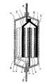
- FIG. 1 is a cross-sectional view of a laminated exterior power storage device that is an example of the power storage device according to the present embodiment.
- the basic configuration of the electricity storage device in the present embodiment shown in FIG. 1 includes a positive electrode 1 containing a nitroxyl compound, a positive electrode current collector 1A connected to the positive electrode 1, and energy connected to the positive electrode current collector 1A outside the cell. And a positive electrode lead 1B to be taken out.
- a negative electrode 2 containing a carbon material capable of reversibly inserting and removing lithium ions, a negative electrode current collector 2A connected to the negative electrode 2, and a negative electrode connected to the negative electrode current collector 2A to extract energy from the cell And leads 2B.
- a lithium supply source 3 for pre-doping the negative electrode 2 a lithium supply source current collector 3 ⁇ / b> A connected to the lithium supply source 3, between the positive electrode 1 and the negative electrode 2, and between the lithium supply source 3 and the positive electrode current collector 1 ⁇ / b> A
- the separator 4 is interposed between the separator 4 that does not conduct electrons but conducts only ions, and the exterior body 5 that seals them.
- the shape of the electricity storage device in this embodiment is not particularly limited.
- a cylindrical shape, a square shape, or the like can be appropriately selected depending on the application.
- the number of electrode layers may be a single layer or a plurality of layers. Further, when there are a plurality of layers, the stacking method or the winding method may be used.
- the positive electrode 1 in this embodiment contains a nitroxyl compound.
- a nitroxyl compound By using a nitroxyl compound, safety and reduction of environmental burden can be realized.
- the nitroxyl compound in the present embodiment is a compound that takes a nitroxyl cation partial structure represented by the formula (I) in an oxidized state and a nitroxyl radical partial structure represented by the formula (II) in a reduced state.
- the nitroxyl compound in an oxidized state, is 2,2,6,6-tetramethylpiperidinoxyl cation represented by the following formula (1), 2, Consists of 2,5,5-tetramethylpyrrolinoxyl cation, 2,2,5,5-tetramethylpyrrolinoxyl cation represented by the following formula (3), and nitronyl cation represented by the following formula (4)
- a polymer compound having one cyclic structure selected from the group is preferable.
- polymer compounds having this cyclic nitroxyl structure in the side chain, among them (meth) acrylate polymers and vinyl ether polymers are preferred.
- the main function of the nitroxyl compound in the positive electrode 1 is a role as an active material contributing to power storage. Therefore, as the proportion of the nitroxyl compound contained in the positive electrode 1 is increased, the energy density is improved.
- the proportion of the nitroxyl compound contained in the positive electrode 1 is not particularly limited, but it is preferable if it is contained in the positive electrode 1 in an amount of 1% by mass or more, and is more preferable if it is 10% by mass or more because a sufficient effect is seen. .
- the content is more preferably 30% by mass or more, and particularly preferably 50% by mass or more.
- the nitroxyl compound preferably has a crosslinked structure from the viewpoint of stability in the charge / discharge cycle.
- the degree of crosslinking of the nitroxyl compound having the crosslinked structure is preferably 0.5 to 6.0 mol%.
- the positive electrode 1 in this embodiment may further contain a conductive auxiliary agent, a binder, and the like.
- the conductive auxiliary agent include carbon materials such as carbon black, acetylene black, and carbon fiber, and conductive polymers such as polyacetylene, polyphenylene, polyaniline, and polypyrrole.
- the binder include resins such as polyvinylidene fluoride, polytetrafluoroethylene, vinylidene fluoride-hexafluoropropylene copolymer, styrene-butadiene copolymer rubber, polypropylene, polyethylene, and polyimide.
- Examples of the material of the positive electrode current collector 1A include aluminum, an aluminum alloy, and stainless steel.
- As the shape, a foil, a flat plate, or a mesh can be used.
- those having holes penetrating the front and back surfaces are preferable.
- a quality foil etc. can be mentioned.
- the shape, number, etc. of the through holes of the positive electrode current collector 1A are such that lithium ions in the electrolyte described later can move between the front and back of the electrode without being blocked by the positive electrode current collector 1A. Therefore, it can be set appropriately so as to be easily closed.
- Examples of the material of the positive electrode lead 1B include aluminum, an aluminum alloy, and stainless steel.
- As the shape, a foil, a flat plate, or a mesh can be used.
- the material of the negative electrode 2 in this embodiment includes a carbon material that can reversibly insert and desorb lithium ions. Specific examples include graphite, hard carbon, polyacene, activated carbon and the like.
- the negative electrode 2 in the present embodiment may include a conductivity imparting agent or a binder.
- the conductivity-imparting agent include carbon materials such as carbon black, acetylene black, and carbon fiber, and metal powder.
- the binder include polyvinylidene fluoride, polytetrafluoroethylene, vinylidene fluoride-hexafluoropropylene copolymer, styrene-butadiene copolymer rubber, polypropylene, polyethylene, and polyimide.
- anode 2 containing a carbon material capable of reversibly inserting and removing lithium ions by using an anode 2 containing a carbon material capable of reversibly inserting and removing lithium ions, and an electrolyte containing a lithium salt and an aprotic organic solvent described later,
- the operating voltage of the device can be increased, and both high energy density and power density can be achieved.
- the balance between the lithium capacity A in which the negative electrode 2 can be inserted / removed in charge / discharge and the lithium capacity C in which the positive electrode 1 can be inserted / removed in charge / discharge is not particularly limited.
- the lithium capacity indicates the capacity of lithium ions.
- the negative electrode The lithium capacity A 2 that can be inserted / removed in charge / discharge is preferably larger than the lithium capacity C that the positive electrode 1 can be inserted / removed in charge / discharge.
- C is preferably 1.1 or more, and more preferably 1.5 or more.
- the ratio A / C is preferably 10 or less, and more preferably 5 or less.
- the lithium capacity A in which the negative electrode 2 can be inserted / removed during charging / discharging is manufactured as a lithium metal counter electrode, charged at a 1 / 40C rate to 0V to lithium ratio, and similarly up to 1V at a 1 / 40C rate. The value measured by repeating the discharging cycle 10 times.
- the lithium capacity C that can be inserted / removed in the charge / discharge of the positive electrode 1 is a lithium metal counter electrode, charged at a rate of 1/10 C to a lithium ratio of 4 V, and also at a rate of 1/10 C up to 3 V The value measured by repeating the discharging cycle 10 times.
- Examples of the material of the negative electrode current collector 2A include copper, nickel, and stainless steel.
- a foil, a flat plate, or a mesh can be used.
- those having holes penetrating the front and back surfaces are preferable.
- a quality foil etc. can be mentioned.
- the shape and number of through-holes of the negative electrode current collector 2A are such that lithium ions in the electrolyte described later can move between the front and back of the electrode without being blocked by the negative electrode current collector 2A. Therefore, it can be set appropriately so as to be easily closed.
- Examples of the material of the negative electrode lead 2B include copper, nickel, and stainless steel.
- a foil, a flat plate, or a mesh can be used.
- the electricity storage device in the present embodiment is in a state where lithium ions are inserted and supported on the negative electrode 2 when the nitroxyl compound contained in the positive electrode 1 is in a discharge state in which the nitroxyl radical partial structure represented by the formula (II) is taken. It is characterized by that. That is, even when the positive electrode 1 is in a completely discharged state, that is, in a state where no energy is stored, the negative electrode 2 is still loaded with lithium ions and is in a partially charged state. It is a feature.
- the negative electrode 2 is the carbon material in which lithium ions are inserted in advance separately from lithium ions involved in the lithium capacity A that can be inserted / removed in charge / discharge. It is characterized by including.
- a positive electrode including a nitroxyl compound having a nitroxyl radical partial structure represented by the formula (II) is used as the positive electrode 1, and lithium ions are inserted into the negative electrode 2 in advance. It is produced using a negative electrode containing the carbon material.
- lithium ions are inserted in advance into the carbon material constituting the negative electrode 2 and used as the negative electrode 2 separately from lithium ions derived from the lithium salt in the electrolyte solution involved in charging and discharging.
- the electrical storage device which concerns on this embodiment can acquire the outstanding stability in a charging / discharging cycle.
- the lithium capacity carried by the negative electrode that is, the lithium capacity previously inserted in the negative electrode 2 is as follows. There is no particular limitation. However, in order to show a sufficient stability improvement effect, it is preferable that 10% or more of lithium capacity A in which the negative electrode 2 can be inserted / removed in charge / discharge and lithium ions are inserted in advance, and 40% or more in advance. More preferably, it is inserted.
- the negative electrode 2 can be inserted / removed in charge / discharge at 200% or less of the lithium capacity A. It is preferable that it is 120% or less.
- the lithium capacity inserted in advance in the negative electrode 2 is that the lithium metal serving as the lithium supply source 3 is inserted into the carbon material in advance when the storage device is a laminate type battery. By measuring the weight of the lithium supply source 3 to be charged, the lithium capacity inserted in advance can be calculated. Further, in the case of a coin-type battery, which will be described later, since lithium ions are inserted while being controlled electrochemically, the lithium capacity inserted in advance can be calculated from the integrated value of the current passed through the cell.
- the method of inserting lithium ions in advance separately from the lithium ions involved in the lithium capacity A that can be inserted into and removed from the negative electrode 2 during charging and discharging there is no particular limitation on the method of inserting lithium ions in advance separately from the lithium ions involved in the lithium capacity A that can be inserted into and removed from the negative electrode 2 during charging and discharging.
- a lithium ion supply source is provided in the power storage device in advance and the lithium ion is inserted by electrochemical contact with the negative electrode 2 or a lithium ion is previously inserted by an electrochemical method.
- Examples include a method for manufacturing an electricity storage device.
- a lithium supply source 3 for inserting lithium ions in advance separately from the lithium ions related to the lithium capacity A that can be inserted / removed in the negative electrode 2 during charging / discharging is provided. .
- the lithium metal of the lithium supply source 3 is inserted and supported on the carbon material of the negative electrode 2 as lithium ions.
- the nitroxyl compound contained in the positive electrode 1 is designed to be in a state in which lithium ions are inserted and supported in the negative electrode 2 when the nitroxyl compound in the discharge state has the nitroxyl radical partial structure represented by the formula (II).
- Examples of the material used as the lithium supply source 3 include lithium metal and lithium aluminum alloy, and lithium metal is particularly preferable.
- Examples of the material of the lithium supply source current collector 3A include copper, nickel, and stainless steel. As the shape, a foil, a flat plate, or a mesh can be used.
- the electricity storage device in the present embodiment is not limited with respect to the amount of lithium ions that the lithium supply source 3 can supply to the negative electrode 2.
- lithium ions are supplied to 10% or more of the lithium capacity A in which the negative electrode 2 can be inserted / removed in charge / discharge, and are inserted / supported. It is preferable that it is 40% or more.
- the negative electrode 2 can be inserted / extracted during charging / discharging at 200% or less of the lithium capacity A.
- Lithium ions are preferably supplied, inserted and supported, and more preferably 120% or less.
- the separator 4 in FIG. 1 is interposed between the positive electrode 1 and the negative electrode 2 and between the lithium supply source 3 and the positive electrode current collector 1A, and plays a role of conducting only ions without conducting electrons.
- the separator 4 is not particularly limited, and a conventionally known separator can be used. Examples thereof include polyolefins such as polypropylene and polyethylene, and porous films such as fluororesin.
- the separator 4 holds an aprotic organic solvent electrolyte containing a lithium salt and is responsible for ion conduction.
- the aprotic organic solvent electrolyte containing a lithium salt preferably has an ionic conductivity of 10 ⁇ 5 to 10 ⁇ 1 S / cm at room temperature.
- lithium salt in the present embodiment examples include LiPF 6 , LiClO 4 , LiBF 4 , LiSbF 6 , LiN (CF 3 SO 2 ) 2 , LiN (C 2 F 5 SO 2 ) 2 , LiB (C 2 O 4 ) 2. Etc.
- the lithium salt is preferably LiBF 4 or LiPF 6 . These may be used alone or in combination of two or more.
- examples of the aprotic organic solvent in this embodiment include cyclic carbonates such as propylene carbonate (PC), ethylene carbonate (EC), butylene carbonate (BC), and vinylene carbonate (VC), dimethyl carbonate (DMC), and diethyl carbonate.
- cyclic carbonates such as propylene carbonate (PC), ethylene carbonate (EC), butylene carbonate (BC), and vinylene carbonate (VC), dimethyl carbonate (DMC), and diethyl carbonate.
- DEC chain carbonates such as ethyl methyl carbonate (EMC), dipropyl carbonate (DPC), aliphatic carboxylic acid esters such as methyl formate, methyl acetate, ethyl propionate, ⁇ -butyrolactone (GBL), etc.
- Lactones chain ethers such as dimethoxyethane (DME), diethoxyethane (DEE) and ethoxymethoxyethane (EME), cyclic ethers such as tetrahydrofuran and methyltetrahydrofuran, 1-ethyl-3-methyl Midazoriumu TFSI, such ionic liquids such as N- butyl -N- methyl-pyrrolidinium TFSI and the like.
- DEC, EC, PC, BC, DME, and GBL are preferable as the aprotic organic solvent.
- These aprotic organic solvents may be used individually by 1 type, or may mix 2 or more types.
- the concentration of the lithium salt relative to the aprotic organic solvent is not particularly limited, but is preferably in the range of 0.4 to 1.5 mol / L from the viewpoint of exhibiting sufficient ionic conductivity.
- the material of the exterior body 5 is not particularly limited, and a conventionally known material can be used.
- a metal material such as iron or aluminum, a plastic material, a glass material, or a composite material obtained by laminating them can be used.
- a laminate film outer package in which aluminum and a polymer film such as nylon or polypropylene are laminated is preferable.
- FIG. 2 is an exploded perspective view of a coin exterior type power storage device which is another example of the power storage device according to the present embodiment.
- the basic configuration of the electricity storage device is connected to the positive electrode 6 containing the nitroxyl compound, the separator 8 made of porous polypropylene or cellulose, the negative electrode 7 containing the carbon material into which lithium ions have been inserted, and the positive electrode 6.
- the method of inserting lithium ions into the negative electrode 7 in advance and carrying it is not particularly limited.
- the negative electrode 7 containing a carbon material is immersed in an electrolytic solution, and lithium ions are electrochemically inserted into the negative electrode 7 using a lithium foil as a counter electrode. Can be carried.
- a lithium foil as a counter electrode.
- other structures, such as material it is the same as that of the laminated exterior type electrical storage device mentioned above.
- the polymer was precipitated in hexane, separated by filtration, and dried under reduced pressure to obtain 18 g (yield 90%) of poly (2,2,6,6-tetramethylpiperidine methacrylate).
- 10 g of the obtained poly (2,2,6,6-tetramethylpiperidine methacrylate) was dissolved in 100 ml of dry-treated dichloromethane.
- 100 ml of a dichloromethane solution of 15.2 g (0.088 mol) of m-chloroperbenzoic acid was added dropwise over 1 hour with stirring at room temperature.
- the structure of the obtained polymer was confirmed by IR.
- the obtained crosslinked product was insoluble in organic solvents such as methanol, ethanol, acetone, ethyl acetate, tetrahydrofuran, dimethylformamide, and dimethyl sulfoxide.
- the structure of the obtained polymer was confirmed by IR.
- the obtained crosslinked product was unnecessary for methanol, ethanol, acetone, ethyl acetate, tetrahydrofuran, dimethylformamide, and dimethyl sulfoxide.
- Table 1 shows the PTMA and crosslinked PTMA synthesized in Synthesis Examples 1-41.
- the solubility with respect to an organic solvent shows the solubility with respect to methanol, ethanol, acetone, ethyl acetate, tetrahydrofuran, dimethylformamide, and dimethylsulfoxide, and if it melt
- the structure of the obtained polymer was confirmed by IR.
- the obtained crosslinked product was insoluble in methanol, ethanol, acetone, ethyl acetate, tetrahydrofuran, dimethylformamide, and dimethyl sulfoxide (organic solvent).
- Table 2 below shows the PTVE and crosslinked PTVE synthesized in Synthesis Examples 42 to 82.
- ⁇ Preparation of positive electrode (polymer content 60 mass%)> 3.6 g of the nitroxyl compound finely divided in advance, 2.1 g of vapor-grown carbon fiber, 240 mg of carboxymethyl cellulose, 60 mg of polytetrafluoroethylene fine powder, and 24 g of water were mixed well to prepare a positive electrode slurry.
- the positive electrode slurry was applied to an expanded metal aluminum current collector with a thickness of 38 ⁇ m, and water was sufficiently vaporized, and then stored overnight at 80 ° C. by vacuum drying to produce a positive electrode containing 60% by mass of a nitroxyl compound. .
- the total thickness of the positive electrode including the current collector was 100 to 400 ⁇ m.
- a positive electrode slurry was prepared by thoroughly mixing 4.2 g of the nitroxyl compound, 1.5 g of vapor-grown carbon fiber, 240 mg of carboxymethyl cellulose, 60 mg of polytetrafluoroethylene fine powder, and 24 g of water.
- the positive electrode slurry was applied to an expanded metal aluminum current collector with a thickness of 38 ⁇ m, and water was sufficiently vaporized, and then stored at 80 ° C. overnight by vacuum drying to produce a positive electrode containing 70% by mass of a nitroxyl compound. .
- the total thickness of the positive electrode including the current collector was 100 to 400 ⁇ m.
- ⁇ Preparation of positive electrode (polymer content 80 mass%)> 4.8 g of the nitroxyl compound finely divided in advance, 0.9 g of vapor-grown carbon fiber, 240 mg of carboxymethyl cellulose, 60 mg of polytetrafluoroethylene fine powder, and 24 g of water were mixed well to prepare a positive electrode slurry.
- the positive electrode slurry was applied to an expanded metal aluminum current collector with a thickness of 38 ⁇ m, and after sufficiently evaporating water, it was stored overnight at 80 ° C. by vacuum drying to produce a positive electrode containing 80% by mass of a nitroxyl compound. .
- the total thickness of the positive electrode including the current collector was 100 to 400 ⁇ m.
- a slurry of the negative electrode was applied to both sides of an expanded metal copper foil having a thickness of 32 ⁇ m coated with a carbon-based conductive paint, and vacuum-dried to prepare a negative electrode containing 90% by mass of graphite.
- Example 1 A positive electrode containing 70% by mass of a nitroxyl compound (PTMA), a negative electrode containing 90% by mass of the graphite, a mixed electrolyte of ethylene carbonate and diethyl carbonate containing a LiPF 6 supporting salt at a concentration of 1 mol / L, a lithium source for pre-doping, Using the resulting lithium foil, a laminate exterior type electricity storage device shown in FIG. 1 was produced.
- PTMA nitroxyl compound
- a negative electrode containing 90% by mass of the graphite a mixed electrolyte of ethylene carbonate and diethyl carbonate containing a LiPF 6 supporting salt at a concentration of 1 mol / L
- LiPF 6 supporting salt a LiPF 6 supporting salt at a concentration of 1 mol / L
- the positive electrode 1 and the negative electrode 2 were sequentially stacked with the separator 4 interposed therebetween to produce an electrode laminate.
- a lithium metal-laminated copper foil serving as the lithium supply source 3 was inserted into the uppermost part of the electrode laminate.
- the aluminum foil as the positive electrode current collector 1A and the positive electrode lead 1B are ultrasonically welded, and the copper foil as the negative electrode current collector 2A, the copper foil as the lithium source current collector 3A, and the negative electrode lead 2B are also welded. did. They were covered with an outer package 5 made of an aluminum laminate film having a thickness of 115 ⁇ m, and the three sides including the lead portions were heat-sealed first.
- the lithium capacity inserted into the negative electrode that is, the lithium capacity previously inserted into the negative electrode
- the film thickness of the electrode is adjusted to 60% of the lithium capacity A that can be inserted / removed in charge / discharge. Further, the film thickness of the electrode is set such that the ratio A / C of the lithium capacity A that can be inserted / removed in charge / discharge of the negative electrode and the lithium capacity C that can be inserted / removed in charge / discharge of the positive electrode becomes 3.0.
- the open electromotive force of the fabricated cell was 3.2V.
- FIG. 2 shows a lithium ion-inserted negative electrode thus obtained, a positive electrode containing 70% by mass of a nitroxyl compound (PTMA), and a mixed electrolyte solution of ethylene carbonate and diethyl carbonate containing a LiPF 6 supporting salt having a concentration of 1 mol / L.
- PTMA nitroxyl compound
- the lithium capacity inserted into the negative electrode that is, the lithium capacity previously inserted into the negative electrode is inserted when the negative electrode is charged / discharged.
- the film thickness of the electrode is adjusted to be 60% of the detachable lithium capacity A. Further, the film thickness of the electrode is set such that the ratio A / C of the lithium capacity A that can be inserted / removed in charge / discharge of the negative electrode and the lithium capacity C that can be inserted / removed in charge / discharge of the positive electrode becomes 3.0 Has been adjusted.
- the open electromotive force of the fabricated cell was 3.2V.
- Example 3 When the nitroxyl compound (PTMA) contained in the positive electrode is in a discharge state having a nitroxyl radical partial structure, the lithium capacity inserted into the negative electrode, that is, the lithium capacity previously inserted into the negative electrode is inserted into the negative electrode during charge / discharge.
- the film thickness of the electrode is adjusted so as to be 5% of the detachable lithium capacity A.
- the film thickness of the electrode is adjusted so that the ratio A / C between the lithium capacity A that can be inserted / removed during charging / discharging and the lithium capacity C that can be inserted / removed during charging / discharging becomes 3.0. It is. Otherwise, a coin-type electricity storage device was produced in the same manner as in Example 2.
- the open electromotive force of the produced cell was 2.7V.
- this cell was repeatedly charged and discharged at a current density of 0.5 mA / cm 2 and a voltage of 3.0 to 4.0 V, a residual capacity of 63% of the initial capacity was obtained after 500 cycles. Furthermore, the capacity retention rate after 500 cycles at 50 ° C. was a residual capacity of 55% of the initial capacity.
- Example 4 When the nitroxyl compound (PTMA) contained in the positive electrode is in a discharge state having a nitroxyl radical partial structure, the lithium capacity inserted into the negative electrode, that is, the lithium capacity previously inserted into the negative electrode is inserted into the negative electrode during charge / discharge.
- the film thickness of the electrode is adjusted to be 10% of the detachable lithium capacity A.
- the film thickness of the electrode is adjusted so that the ratio A / C between the lithium capacity A that can be inserted / removed during charging / discharging and the lithium capacity C that can be inserted / removed during charging / discharging becomes 3.0. It is. Otherwise, a coin-type electricity storage device was produced in the same manner as in Example 2.
- the open electromotive force of the produced cell was 3.0V.
- this cell was repeatedly charged and discharged at a current density of 0.5 mA / cm 2 and a voltage in the range of 3.0 to 4.0 V, a residual capacity of 83% of the initial capacity was obtained after 500 cycles. Furthermore, the capacity retention rate after 500 cycles at 50 ° C. was a residual capacity of 76% of the initial capacity.
- Example 5 When the nitroxyl compound (PTMA) contained in the positive electrode is in a discharge state having a nitroxyl radical partial structure, the lithium capacity inserted into the negative electrode, that is, the lithium capacity previously inserted into the negative electrode is inserted into the negative electrode during charge / discharge.
- the film thickness of the electrode is adjusted to 40% of the detachable lithium capacity A.
- the film thickness of the electrode is adjusted so that the ratio A / C between the lithium capacity A that can be inserted / removed during charging / discharging and the lithium capacity C that can be inserted / removed during charging / discharging becomes 3.0. It is. Otherwise, a coin-type electricity storage device was produced in the same manner as in Example 2.
- the open electromotive force of the fabricated cell was 3.1V.
- this cell was repeatedly charged and discharged at a current density of 0.5 mA / cm 2 and a voltage of 3.0 to 4.0 V, a residual capacity of 92% of the initial capacity was obtained after 500 cycles. Furthermore, the capacity retention rate after 500 cycles at 50 ° C. was a residual capacity of 84% of the initial capacity.
- Example 6 When the nitroxyl compound (PTMA) contained in the positive electrode is in a discharge state having a nitroxyl radical partial structure, the lithium capacity inserted into the negative electrode, that is, the lithium capacity previously inserted into the negative electrode is inserted into the negative electrode during charge / discharge.
- the film thickness of the electrode is adjusted to be 120% of the detachable lithium capacity A.
- the film thickness of the electrode is adjusted so that the ratio A / C between the lithium capacity A that can be inserted / removed during charging / discharging and the lithium capacity C that can be inserted / removed during charging / discharging becomes 3.0. It is. Otherwise, a coin-type electricity storage device was produced in the same manner as in Example 2.
- the open electromotive force of the fabricated cell was 3.3V.
- this cell was repeatedly charged and discharged at a current density of 0.5 mA / cm 2 and a voltage of 3.0 to 4.0 V, a residual capacity of 92% of the initial capacity was obtained after 500 cycles. Furthermore, the capacity retention rate after 500 cycles at 50 ° C. was a residual capacity of 80% of the initial capacity.
- Example 7 When the nitroxyl compound (PTMA) contained in the positive electrode is in a discharge state having a nitroxyl radical partial structure, the lithium capacity inserted into the negative electrode, that is, the lithium capacity previously inserted into the negative electrode is inserted into the negative electrode during charge / discharge.
- the film thickness of the electrode is adjusted to be 200% of the detachable lithium capacity A.
- the film thickness of the electrode is adjusted so that the ratio A / C between the lithium capacity A that can be inserted / removed during charging / discharging and the lithium capacity C that can be inserted / removed during charging / discharging becomes 3.0. It is. Otherwise, a coin-type electricity storage device was produced in the same manner as in Example 2.
- the open electromotive force of the fabricated cell was 3.3V.
- this cell was repeatedly charged and discharged at a current density of 0.5 mA / cm 2 and a voltage of 3.0 to 4.0 V, a residual capacity of 85% of the initial capacity was obtained after 500 cycles. Furthermore, the capacity retention rate after 500 cycles at 50 ° C. was a residual capacity of 76% of the initial capacity.
- Example 8 When the nitroxyl compound (PTMA) contained in the positive electrode is in a discharge state having a nitroxyl radical partial structure, the lithium capacity inserted into the negative electrode, that is, the lithium capacity previously inserted into the negative electrode is inserted into the negative electrode during charge / discharge.
- the film thickness of the electrode is adjusted to be 250% of the detachable lithium capacity A.
- the film thickness of the electrode is adjusted so that the ratio A / C between the lithium capacity A that can be inserted / removed during charging / discharging and the lithium capacity C that can be inserted / removed during charging / discharging becomes 3.0. It is. Otherwise, a coin-type electricity storage device was produced in the same manner as in Example 2.
- the open electromotive force of the fabricated cell was 3.4V.
- this cell was repeatedly charged and discharged at a current density of 0.5 mA / cm 2 and a voltage of 3.0 to 4.0 V, a residual capacity of 71% of the initial capacity was obtained after 500 cycles. Furthermore, the capacity retention rate after 500 cycles at 50 ° C. was a residual capacity of 62% of the initial capacity.
- Example 9 When the nitroxyl compound (PTMA) contained in the positive electrode is in a discharge state having a nitroxyl radical partial structure, the lithium capacity inserted into the negative electrode, that is, the lithium capacity previously inserted into the negative electrode is inserted into the negative electrode during charge / discharge.
- the film thickness of the electrode is adjusted to 40% of the detachable lithium capacity A.
- the film thickness of the electrode is adjusted so that the ratio A / C between the lithium capacity A that can be inserted / removed during charging / discharging and the lithium capacity C that can be inserted / removed during charging / discharging becomes 1.0. It is. Otherwise, a coin-type electricity storage device was produced in the same manner as in Example 2.
- the open electromotive force of the fabricated cell was 3.2V.
- this cell was repeatedly charged and discharged at a current density of 0.5 mA / cm 2 and a voltage of 3.0 to 4.0 V, a residual capacity of 23% of the initial capacity was obtained after 500 cycles. Further, the capacity retention rate after 500 cycles at 50 ° C. was a residual capacity of 11% of the initial capacity.
- Example 10 When the nitroxyl compound (PTMA) contained in the positive electrode is in a discharge state having a nitroxyl radical partial structure, the lithium capacity inserted into the negative electrode, that is, the lithium capacity previously inserted into the negative electrode is inserted into the negative electrode during charge / discharge.
- the film thickness of the electrode is adjusted to 40% of the detachable lithium capacity A.
- the film thickness of the electrode is adjusted so that the ratio A / C between the lithium capacity A that can be inserted / removed during charge / discharge and the lithium capacity C that can be inserted / removed during charge / discharge is 1.1. It is. Otherwise, a coin-type electricity storage device was produced in the same manner as in Example 2.
- the open electromotive force of the fabricated cell was 3.2V.
- this cell was repeatedly charged and discharged at a current density of 0.5 mA / cm 2 and a voltage in the range of 3.0 to 4.0 V, a residual capacity of 72% of the initial capacity was obtained after 500 cycles. Furthermore, the capacity retention rate after 500 cycles at 50 ° C. was a residual capacity of 60% of the initial capacity.
- Example 11 When the nitroxyl compound (PTMA) contained in the positive electrode is in a discharge state having a nitroxyl radical partial structure, the lithium capacity inserted into the negative electrode, that is, the lithium capacity previously inserted into the negative electrode is inserted into the negative electrode during charge / discharge.
- the film thickness of the electrode is adjusted to 40% of the detachable lithium capacity A.
- the film thickness of the electrode is adjusted so that the ratio A / C between the lithium capacity A that can be inserted / removed during charge / discharge and the lithium capacity C that can be inserted / removed during charge / discharge is 1.5. It is. Otherwise, a coin-type electricity storage device was produced in the same manner as in Example 2.
- the open electromotive force of the fabricated cell was 3.2V.
- Example 12 When the nitroxyl compound (PTMA) contained in the positive electrode is in a discharge state having a nitroxyl radical partial structure, the lithium capacity inserted into the negative electrode, that is, the lithium capacity previously inserted into the negative electrode is inserted into the negative electrode during charge / discharge.
- the film thickness of the electrode is adjusted to be 60% of the detachable lithium capacity A.
- the film thickness of the electrode is adjusted so that the ratio A / C between the lithium capacity A that can be inserted / removed during charge / discharge and the lithium capacity C that can be inserted / removed during charge / discharge is 5.0. It is. Otherwise, a coin-type electricity storage device was produced in the same manner as in Example 2.
- the open electromotive force of the fabricated cell was 3.2V.
- this cell was repeatedly charged and discharged at a current density of 0.5 mA / cm 2 and a voltage in the range of 3.0 to 4.0 V, a residual capacity of 90% of the initial capacity was obtained after 500 cycles. Furthermore, the capacity retention rate after 500 cycles at 50 ° C. was a residual capacity of 79% of the initial capacity.
- Example 13 When the nitroxyl compound (PTMA) contained in the positive electrode is in a discharge state having a nitroxyl radical partial structure, the lithium capacity inserted into the negative electrode, that is, the lithium capacity previously inserted into the negative electrode is inserted into the negative electrode during charge / discharge.
- the film thickness of the electrode is adjusted to be 60% of the detachable lithium capacity A.
- the film thickness of the electrode is adjusted so that the ratio A / C between the lithium capacity A that can be inserted / removed during charge / discharge and the lithium capacity C that can be inserted / removed during charge / discharge is 10.0. It is. Otherwise, a coin-type electricity storage device was produced in the same manner as in Example 2.
- the open electromotive force of the fabricated cell was 3.1V.
- this cell was repeatedly charged and discharged at a current density of 0.5 mA / cm 2 and a voltage of 3.0 to 4.0 V, a residual capacity of 85% of the initial capacity was obtained after 500 cycles. Furthermore, the capacity retention rate after 500 cycles at 50 ° C. was a residual capacity of 71% of the initial capacity.
- Example 14 When the nitroxyl compound (PTMA) contained in the positive electrode is in a discharge state having a nitroxyl radical partial structure, the lithium capacity inserted into the negative electrode, that is, the lithium capacity previously inserted into the negative electrode is inserted into the negative electrode during charge / discharge.
- the film thickness of the electrode is adjusted to be 60% of the detachable lithium capacity A.
- the film thickness of the electrode is adjusted so that the ratio A / C between the lithium capacity A that can be inserted / removed during charge / discharge and the lithium capacity C that can be inserted / removed during charge / discharge is 15.0. It is. Otherwise, a coin-type electricity storage device was produced in the same manner as in Example 2.
- the open electromotive force of the fabricated cell was 3.2V.
- this cell was repeatedly charged and discharged at a current density of 0.5 mA / cm 2 and a voltage of 3.0 to 4.0 V, a residual capacity of 77% of the initial capacity was obtained after 500 cycles. Furthermore, the capacity retention rate after 500 cycles at 50 ° C. was a residual capacity of 66% of the initial capacity.
- Examples 15 to 76> The cross-linked polymer (cross-linked PTMA, cross-linked PTVE) shown in the above synthesis example is used as the nitroxyl compound, and further, any of ethylene carbonate / diethyl carbonate mixed solvent, propylene carbonate, and ⁇ -butyrolactone is used as the electrolyte solvent, and the supporting salt is used. Batteries (coin type and laminate type) were produced and evaluated in the same manner as in Examples 1 to 14 except that either LiPF 6 or LiBF 4 was used.
- a laminated exterior type electricity storage device was produced in the same manner as in Example 1 without using a lithium foil as a supply source. Since lithium ions are not inserted into the negative electrode in advance, the electricity storage device has no lithium ions inserted into the negative electrode when the nitroxyl compound (PTMA) contained in the positive electrode has a nitroxyl radical partial structure.
- the electrode film thickness is adjusted so that the ratio A / C between the lithium capacity A that can be inserted / removed during charge / discharge of the negative electrode and the lithium capacity C that can be inserted / removed during charge / discharge of the positive electrode is 1.0. It is.
- the open electromotive force of the fabricated cell was -0.1V. When this cell was repeatedly charged and discharged at a current density of 0.5 mA / cm 2 and a voltage of 3.0 to 4.0 V, a residual capacity of 34% of the initial capacity was obtained after 500 cycles. Furthermore, the capacity retention rate after 500 cycles at 50 ° C. was a residual capacity of 10% of the initial capacity.
- a coin-type electricity storage device was prepared in the same manner as in Example 2 using the mixed electrolyte solution. Since lithium ions are not inserted into the negative electrode in advance, the electricity storage device has no lithium ions inserted into the negative electrode when the nitroxyl compound (PTMA) contained in the positive electrode has a nitroxyl radical partial structure.
- the electrode film thickness is adjusted so that the ratio A / C between the lithium capacity A that can be inserted / removed during charge / discharge of the negative electrode and the lithium capacity C that can be inserted / removed during charge / discharge of the positive electrode is 1.0. It is.
- the open electromotive force of the fabricated cell was -0.2V. When this cell was repeatedly charged and discharged at a current density of 0.5 mA / cm 2 and a voltage in the range of 3.0 to 4.0 V, a residual capacity of 24% of the initial capacity was obtained after 500 cycles. Furthermore, the capacity retention rate after 500 cycles at 50 ° C. was a residual capacity of 8% of the initial capacity.
- a coin-type electricity storage device was prepared in the same manner as in Example 2 using the mixed electrolyte solution. Since lithium ions are not inserted into the negative electrode in advance, the electricity storage device has no lithium ions inserted into the negative electrode when the nitroxyl compound (PTMA) contained in the positive electrode has a nitroxyl radical partial structure.
- the electrode thickness was adjusted so that the ratio A / C between the lithium capacity A that can be inserted / removed during charge / discharge of the negative electrode and the lithium capacity C that can be inserted / removed during charge / discharge of the positive electrode was 3.0. It is.
- the open electromotive force of the fabricated cell was -0.1V. When this cell was repeatedly charged and discharged at a current density of 0.5 mA / cm 2 and a voltage of 3.0 to 4.0 V, a residual capacity of 22% of the initial capacity was obtained after 500 cycles. Furthermore, the capacity retention rate after 500 cycles at 50 ° C. was a residual capacity of 6% of the initial capacity.
- a positive electrode containing 70% by mass of a nitroxyl compound (PTVE), a negative electrode not containing lithium ions containing 90% by mass of graphite, and a mixed electrolyte of ethylene carbonate and diethyl carbonate containing a LiPF6 supporting salt with a concentration of 1 mol / L A coin-type electricity storage device was manufactured. Since lithium ions are not inserted into the negative electrode in advance, lithium ions are not inserted into the negative electrode when the nitroxyl compound (PTVE) contained in the positive electrode is in a discharge state having a nitroxyl radical partial structure.
- the electrode film thickness is adjusted so that the ratio A / C between the lithium capacity A that can be inserted / removed during charge / discharge of the negative electrode and the lithium capacity C that can be inserted / removed during charge / discharge of the positive electrode is 1.0. It is.
- the open electromotive force of the fabricated cell was -0.1V. When this cell was repeatedly charged and discharged at a current density of 0.5 mA / cm 2 and a voltage of 3.0 to 4.0 V, a residual capacity of 13% of the initial capacity was obtained after 500 cycles. Furthermore, the capacity retention rate after 500 cycles at 50 ° C. was a residual capacity of 4% of the initial capacity.
- the nitroxyl compound contained in the positive electrode was converted into a nitroxyl radical. It has been clarified that the open electromotive force is greatly increased and the stability against the charge / discharge cycle is improved by the lithium ion inserted into the negative electrode in the discharge state having the partial structure.
- the ratio of the lithium capacity inserted in advance into the negative electrode to the lithium capacity A is preferably in the range of 10% or more and 200% or less, and 40% or more and 120% or less. It turned out that it is more preferable.
- the ratio A / C between the lithium capacity A and the lithium capacity C is preferably in the range of 1.1 or more and 10.0 or less, 1.5 or more, It turned out that it is more preferable to exist in the range of 5.0 or less. From the results of Examples 17 to 76, it was revealed that the stability was improved even when a crosslinked polymer was used as the nitroxyl compound. Further, it was shown that the electrolyte solution was excellent in stability even when any of ethylene carbonate / diethyl carbonate mixed solvent, propylene carbonate, and ⁇ -butyrolactone was used. Furthermore, it has been clarified that either LiBF 4 or LiPF 6 is used as the supporting salt, which is excellent in stability. A comparison between Example 1 and Examples 52 to 56 and other examples shows that the device has high stability even when a laminated cell is used as well as a coin-type cell.
- the electricity storage device in the present invention can simultaneously achieve high energy density, high output characteristics, low environmental load, and high safety. For this reason, power storage devices for driving or auxiliary use such as electric vehicles and hybrid electric vehicles, power sources for various portable electronic devices that require high output, power storage devices for various types of energy such as solar energy and wind power generation, or household appliances It can be used as a storage power source or the like.
Abstract
Priority Applications (2)
| Application Number | Priority Date | Filing Date | Title |
|---|---|---|---|
| US13/375,666 US8617744B2 (en) | 2009-06-02 | 2010-05-26 | Electricity storage device |
| JP2011518407A JP5516578B2 (ja) | 2009-06-02 | 2010-05-26 | 蓄電デバイス |
Applications Claiming Priority (4)
| Application Number | Priority Date | Filing Date | Title |
|---|---|---|---|
| JP2009-132950 | 2009-06-02 | ||
| JP2009132950 | 2009-06-02 | ||
| JP2009253029 | 2009-11-04 | ||
| JP2009-253029 | 2009-11-04 |
Publications (1)
| Publication Number | Publication Date |
|---|---|
| WO2010140512A1 true WO2010140512A1 (fr) | 2010-12-09 |
Family
ID=43297648
Family Applications (1)
| Application Number | Title | Priority Date | Filing Date |
|---|---|---|---|
| PCT/JP2010/058875 WO2010140512A1 (fr) | 2009-06-02 | 2010-05-26 | Dispositif accumulateur d'énergie électrique |
Country Status (3)
| Country | Link |
|---|---|
| US (1) | US8617744B2 (fr) |
| JP (1) | JP5516578B2 (fr) |
| WO (1) | WO2010140512A1 (fr) |
Cited By (16)
| Publication number | Priority date | Publication date | Assignee | Title |
|---|---|---|---|---|
| WO2014136729A1 (fr) * | 2013-03-04 | 2014-09-12 | 日本電気株式会社 | Dispositif de stockage d'électricité |
| JP2015060636A (ja) * | 2013-09-17 | 2015-03-30 | 日本電気株式会社 | 二次電池 |
| JP2015122309A (ja) * | 2013-11-22 | 2015-07-02 | 日本電気株式会社 | 蓄電デバイス及びその製造方法 |
| DE102014003300A1 (de) | 2014-03-07 | 2015-09-10 | Evonik Degussa Gmbh | Neue Tetracyanoanthrachinondimethanpolymere und deren Verwendung |
| DE102014004760A1 (de) | 2014-03-28 | 2015-10-01 | Evonik Degussa Gmbh | Neue 9,10-Bis(1,3-dithiol-2-yliden)-9,10-dihydroanthracenpolymere und deren Verwendung |
| JP2016536427A (ja) * | 2013-09-09 | 2016-11-24 | ユニヴェルシテ・カトリック・ドゥ・ルーヴァン | 導電性ポリマーコンポジットの調製方法 |
| EP3135704A1 (fr) | 2015-08-26 | 2017-03-01 | Evonik Degussa GmbH | Utilisation de certains polymeres en tant qu'accumulateurs de charge |
| EP3136410A1 (fr) | 2015-08-26 | 2017-03-01 | Evonik Degussa GmbH | Utilisation de certains polymeres en tant qu'accumulateurs de charge |
| EP3279223A1 (fr) | 2016-08-05 | 2018-02-07 | Evonik Degussa GmbH | Utilisation de polymères contenant du thianthrène en tant qu'accumulateurs de charge |
| WO2018024901A1 (fr) | 2016-08-05 | 2018-02-08 | Evonik Degussa Gmbh | Utilisation de polymères contenant du thianthrène comme accumulateurs de charges |
| WO2018046387A1 (fr) | 2016-09-06 | 2018-03-15 | Evonik Degussa Gmbh | Procédé d'oxydation améliorée de groupes aminés secondaires |
| DE102017005924A1 (de) | 2017-06-23 | 2018-12-27 | Friedrich-Schiller-Universität Jena | Verwendung benzotriazinyl-haltiger Polymere als Ladungsspeicher |
| JP2019036506A (ja) * | 2017-08-21 | 2019-03-07 | 株式会社クラレ | 有機化合物を活物質とした正極を含んでなる電池用負極、及び該負極と有機化合物を活物質とした正極を含んでなる電池 |
| US10756348B2 (en) | 2015-08-26 | 2020-08-25 | Evonik Operations Gmbh | Use of certain polymers as a charge store |
| US10844145B2 (en) | 2016-06-02 | 2020-11-24 | Evonik Operations Gmbh | Method for producing an electrode material |
| US10957907B2 (en) | 2015-08-26 | 2021-03-23 | Evonik Operations Gmbh | Use of certain polymers as a charge store |
Families Citing this family (7)
| Publication number | Priority date | Publication date | Assignee | Title |
|---|---|---|---|---|
| US9779885B2 (en) | 2012-11-09 | 2017-10-03 | Corning Incorporated | Method of pre-doping a lithium ion capacitor |
| WO2016147811A1 (fr) * | 2015-03-16 | 2016-09-22 | 日本電気株式会社 | Dispositif de stockage d'électricité |
| US10637040B2 (en) * | 2016-07-28 | 2020-04-28 | GM Global Technology Operations LLC | Blended or multi-coated electrodes for lithium ion battery and capacitor hybrid system |
| US10693176B2 (en) | 2016-07-28 | 2020-06-23 | GM Global Technology Operations LLC | Hybrid cell design of alternatively stacked or wound lithium ion battery and capacitor electrodes |
| US11830672B2 (en) | 2016-11-23 | 2023-11-28 | KYOCERA AVX Components Corporation | Ultracapacitor for use in a solder reflow process |
| US10658663B2 (en) * | 2017-09-05 | 2020-05-19 | GM Global Technology Operations LLC | Electrode designs for lithium ion battery and capacitor hybrid system |
| US20190341648A1 (en) * | 2018-05-07 | 2019-11-07 | Gm Global Technology Operaitons Llc | Hole-containing electrode designs for lithium ion battery and capacitor hybrid systems |
Citations (4)
| Publication number | Priority date | Publication date | Assignee | Title |
|---|---|---|---|---|
| WO2005078830A1 (fr) * | 2004-02-16 | 2005-08-25 | Nec Corporation | Dispositif de stockage électrique |
| JP2006303330A (ja) * | 2005-04-22 | 2006-11-02 | Fuji Heavy Ind Ltd | リチウムイオンキャパシタ |
| JP2007213992A (ja) * | 2006-02-09 | 2007-08-23 | Denso Corp | 二次電池用電極及び該電極を用いた二次電池 |
| WO2008059846A1 (fr) * | 2006-11-16 | 2008-05-22 | Panasonic Corporation | Dispositif de stockage d'électricité |
Family Cites Families (3)
| Publication number | Priority date | Publication date | Assignee | Title |
|---|---|---|---|---|
| JP4687848B2 (ja) | 2001-04-03 | 2011-05-25 | 日本電気株式会社 | 蓄電デバイス |
| JP2006286919A (ja) | 2005-03-31 | 2006-10-19 | Fuji Heavy Ind Ltd | リチウムイオンキャパシタ |
| JP2008252013A (ja) | 2007-03-30 | 2008-10-16 | Fuji Heavy Ind Ltd | リチウムイオンキャパシタ |
-
2010
- 2010-05-26 JP JP2011518407A patent/JP5516578B2/ja active Active
- 2010-05-26 US US13/375,666 patent/US8617744B2/en active Active
- 2010-05-26 WO PCT/JP2010/058875 patent/WO2010140512A1/fr active Application Filing
Patent Citations (4)
| Publication number | Priority date | Publication date | Assignee | Title |
|---|---|---|---|---|
| WO2005078830A1 (fr) * | 2004-02-16 | 2005-08-25 | Nec Corporation | Dispositif de stockage électrique |
| JP2006303330A (ja) * | 2005-04-22 | 2006-11-02 | Fuji Heavy Ind Ltd | リチウムイオンキャパシタ |
| JP2007213992A (ja) * | 2006-02-09 | 2007-08-23 | Denso Corp | 二次電池用電極及び該電極を用いた二次電池 |
| WO2008059846A1 (fr) * | 2006-11-16 | 2008-05-22 | Panasonic Corporation | Dispositif de stockage d'électricité |
Cited By (20)
| Publication number | Priority date | Publication date | Assignee | Title |
|---|---|---|---|---|
| WO2014136729A1 (fr) * | 2013-03-04 | 2014-09-12 | 日本電気株式会社 | Dispositif de stockage d'électricité |
| JP2016536427A (ja) * | 2013-09-09 | 2016-11-24 | ユニヴェルシテ・カトリック・ドゥ・ルーヴァン | 導電性ポリマーコンポジットの調製方法 |
| JP2015060636A (ja) * | 2013-09-17 | 2015-03-30 | 日本電気株式会社 | 二次電池 |
| JP2015122309A (ja) * | 2013-11-22 | 2015-07-02 | 日本電気株式会社 | 蓄電デバイス及びその製造方法 |
| US9890230B2 (en) | 2014-03-07 | 2018-02-13 | Evonik Degussa Gmbh | Tetracyanoanthraquinodimethane polymers and use thereof |
| DE102014003300A1 (de) | 2014-03-07 | 2015-09-10 | Evonik Degussa Gmbh | Neue Tetracyanoanthrachinondimethanpolymere und deren Verwendung |
| US10263280B2 (en) | 2014-03-28 | 2019-04-16 | Evonik Degussa Gmbh | 9,10-Bis(1,3-dithiol-2-ylidene)-9,10-dihydroanthracene polymers and use thereof |
| DE102014004760A1 (de) | 2014-03-28 | 2015-10-01 | Evonik Degussa Gmbh | Neue 9,10-Bis(1,3-dithiol-2-yliden)-9,10-dihydroanthracenpolymere und deren Verwendung |
| EP3135704A1 (fr) | 2015-08-26 | 2017-03-01 | Evonik Degussa GmbH | Utilisation de certains polymeres en tant qu'accumulateurs de charge |
| EP3136410A1 (fr) | 2015-08-26 | 2017-03-01 | Evonik Degussa GmbH | Utilisation de certains polymeres en tant qu'accumulateurs de charge |
| US10957907B2 (en) | 2015-08-26 | 2021-03-23 | Evonik Operations Gmbh | Use of certain polymers as a charge store |
| US10756348B2 (en) | 2015-08-26 | 2020-08-25 | Evonik Operations Gmbh | Use of certain polymers as a charge store |
| US10844145B2 (en) | 2016-06-02 | 2020-11-24 | Evonik Operations Gmbh | Method for producing an electrode material |
| EP3279223A1 (fr) | 2016-08-05 | 2018-02-07 | Evonik Degussa GmbH | Utilisation de polymères contenant du thianthrène en tant qu'accumulateurs de charge |
| US10608255B2 (en) | 2016-08-05 | 2020-03-31 | Evonik Operations Gmbh | Use of thianthrene-containing polymers as a charge store |
| WO2018024901A1 (fr) | 2016-08-05 | 2018-02-08 | Evonik Degussa Gmbh | Utilisation de polymères contenant du thianthrène comme accumulateurs de charges |
| WO2018046387A1 (fr) | 2016-09-06 | 2018-03-15 | Evonik Degussa Gmbh | Procédé d'oxydation améliorée de groupes aminés secondaires |
| US11001659B1 (en) | 2016-09-06 | 2021-05-11 | Evonik Operations Gmbh | Method for the improved oxidation of secondary amine groups |
| DE102017005924A1 (de) | 2017-06-23 | 2018-12-27 | Friedrich-Schiller-Universität Jena | Verwendung benzotriazinyl-haltiger Polymere als Ladungsspeicher |
| JP2019036506A (ja) * | 2017-08-21 | 2019-03-07 | 株式会社クラレ | 有機化合物を活物質とした正極を含んでなる電池用負極、及び該負極と有機化合物を活物質とした正極を含んでなる電池 |
Also Published As
| Publication number | Publication date |
|---|---|
| JP5516578B2 (ja) | 2014-06-11 |
| US8617744B2 (en) | 2013-12-31 |
| US20120100437A1 (en) | 2012-04-26 |
| JPWO2010140512A1 (ja) | 2012-11-15 |
Similar Documents
| Publication | Publication Date | Title |
|---|---|---|
| JP5516578B2 (ja) | 蓄電デバイス | |
| JP5228531B2 (ja) | 蓄電デバイス | |
| JP5146049B2 (ja) | 蓄電デバイス | |
| JP5076560B2 (ja) | 蓄電デバイス | |
| JP5625151B2 (ja) | ラジカルを有する化合物、重合体、およびその重合体を用いた蓄電デバイス | |
| JP6153124B2 (ja) | 非水電解液二次電池およびその製造方法 | |
| JPWO2019194094A1 (ja) | 蓄電デバイス用セパレータ、蓄電デバイスおよびそれらの製造方法 | |
| KR20200118470A (ko) | 에스테르 및 에테르 단위의 공중합체, 이의 생산 방법 및 이의 용도 | |
| WO2014092016A1 (fr) | Dispositif de stockage électrique | |
| KR20150031688A (ko) | 복합양극활물질, 그 제조방법 및 이를 채용한 양극과 리튬이차전지 | |
| JP7092037B2 (ja) | ラジカルポリマーを用いた電極及び二次電池 | |
| JP7115318B2 (ja) | ラジカルポリマーを用いた電極及び二次電池 | |
| US10497978B2 (en) | Power storage device | |
| JP5282259B2 (ja) | 分子クラスター二次電池 | |
| US20210273226A1 (en) | Secondary battery using radical polymer in an electrode | |
| JP2004200058A (ja) | 蓄電デバイス | |
| JP5896154B2 (ja) | 固体電解質膜形成剤、およびそれを含有する電解液、蓄電デバイス | |
| JP6447050B2 (ja) | 蓄電デバイスの製造方法 | |
| WO2014136729A1 (fr) | Dispositif de stockage d'électricité | |
| WO2014157059A1 (fr) | Électrode pour dispositif de stockage d'électricité et dispositif de stockage d'électricité utilisant ladite électrode | |
| WO2014092128A1 (fr) | Dispositif de stockage électrique | |
| WO2013114785A1 (fr) | Dispositif de stockage d'électricité |
Legal Events
| Date | Code | Title | Description |
|---|---|---|---|
| 121 | Ep: the epo has been informed by wipo that ep was designated in this application |
Ref document number: 10783296 Country of ref document: EP Kind code of ref document: A1 |
|
| WWE | Wipo information: entry into national phase |
Ref document number: 13375666 Country of ref document: US |
|
| NENP | Non-entry into the national phase |
Ref country code: DE |
|
| WWE | Wipo information: entry into national phase |
Ref document number: 2011518407 Country of ref document: JP |
|
| 122 | Ep: pct application non-entry in european phase |
Ref document number: 10783296 Country of ref document: EP Kind code of ref document: A1 |