WO2010140310A1 - 樹脂押出用ダイ及びそれを用いた押出成型方法 - Google Patents
樹脂押出用ダイ及びそれを用いた押出成型方法 Download PDFInfo
- Publication number
- WO2010140310A1 WO2010140310A1 PCT/JP2010/003356 JP2010003356W WO2010140310A1 WO 2010140310 A1 WO2010140310 A1 WO 2010140310A1 JP 2010003356 W JP2010003356 W JP 2010003356W WO 2010140310 A1 WO2010140310 A1 WO 2010140310A1
- Authority
- WO
- WIPO (PCT)
- Prior art keywords
- resin
- discharge nozzle
- eyes
- extrusion
- discharge
- Prior art date
- Legal status (The legal status is an assumption and is not a legal conclusion. Google has not performed a legal analysis and makes no representation as to the accuracy of the status listed.)
- Ceased
Links
Images










Classifications
-
- B—PERFORMING OPERATIONS; TRANSPORTING
- B29—WORKING OF PLASTICS; WORKING OF SUBSTANCES IN A PLASTIC STATE IN GENERAL
- B29B—PREPARATION OR PRETREATMENT OF THE MATERIAL TO BE SHAPED; MAKING GRANULES OR PREFORMS; RECOVERY OF PLASTICS OR OTHER CONSTITUENTS OF WASTE MATERIAL CONTAINING PLASTICS
- B29B9/00—Making granules
- B29B9/02—Making granules by dividing preformed material
- B29B9/06—Making granules by dividing preformed material in the form of filamentary material, e.g. combined with extrusion
-
- B—PERFORMING OPERATIONS; TRANSPORTING
- B29—WORKING OF PLASTICS; WORKING OF SUBSTANCES IN A PLASTIC STATE IN GENERAL
- B29B—PREPARATION OR PRETREATMENT OF THE MATERIAL TO BE SHAPED; MAKING GRANULES OR PREFORMS; RECOVERY OF PLASTICS OR OTHER CONSTITUENTS OF WASTE MATERIAL CONTAINING PLASTICS
- B29B7/00—Mixing; Kneading
- B29B7/30—Mixing; Kneading continuous, with mechanical mixing or kneading devices
- B29B7/58—Component parts, details or accessories; Auxiliary operations
- B29B7/72—Measuring, controlling or regulating
- B29B7/726—Measuring properties of mixture, e.g. temperature or density
-
- B—PERFORMING OPERATIONS; TRANSPORTING
- B29—WORKING OF PLASTICS; WORKING OF SUBSTANCES IN A PLASTIC STATE IN GENERAL
- B29B—PREPARATION OR PRETREATMENT OF THE MATERIAL TO BE SHAPED; MAKING GRANULES OR PREFORMS; RECOVERY OF PLASTICS OR OTHER CONSTITUENTS OF WASTE MATERIAL CONTAINING PLASTICS
- B29B7/00—Mixing; Kneading
- B29B7/80—Component parts, details or accessories; Auxiliary operations
- B29B7/88—Adding charges, i.e. additives
- B29B7/90—Fillers or reinforcements, e.g. fibres
-
- B—PERFORMING OPERATIONS; TRANSPORTING
- B29—WORKING OF PLASTICS; WORKING OF SUBSTANCES IN A PLASTIC STATE IN GENERAL
- B29B—PREPARATION OR PRETREATMENT OF THE MATERIAL TO BE SHAPED; MAKING GRANULES OR PREFORMS; RECOVERY OF PLASTICS OR OTHER CONSTITUENTS OF WASTE MATERIAL CONTAINING PLASTICS
- B29B9/00—Making granules
- B29B9/12—Making granules characterised by structure or composition
-
- B—PERFORMING OPERATIONS; TRANSPORTING
- B29—WORKING OF PLASTICS; WORKING OF SUBSTANCES IN A PLASTIC STATE IN GENERAL
- B29B—PREPARATION OR PRETREATMENT OF THE MATERIAL TO BE SHAPED; MAKING GRANULES OR PREFORMS; RECOVERY OF PLASTICS OR OTHER CONSTITUENTS OF WASTE MATERIAL CONTAINING PLASTICS
- B29B9/00—Making granules
- B29B9/12—Making granules characterised by structure or composition
- B29B9/14—Making granules characterised by structure or composition fibre-reinforced
-
- B—PERFORMING OPERATIONS; TRANSPORTING
- B29—WORKING OF PLASTICS; WORKING OF SUBSTANCES IN A PLASTIC STATE IN GENERAL
- B29C—SHAPING OR JOINING OF PLASTICS; SHAPING OF MATERIAL IN A PLASTIC STATE, NOT OTHERWISE PROVIDED FOR; AFTER-TREATMENT OF THE SHAPED PRODUCTS, e.g. REPAIRING
- B29C48/00—Extrusion moulding, i.e. expressing the moulding material through a die or nozzle which imparts the desired form; Apparatus therefor
- B29C48/001—Combinations of extrusion moulding with other shaping operations
- B29C48/0018—Combinations of extrusion moulding with other shaping operations combined with shaping by orienting, stretching or shrinking, e.g. film blowing
-
- B—PERFORMING OPERATIONS; TRANSPORTING
- B29—WORKING OF PLASTICS; WORKING OF SUBSTANCES IN A PLASTIC STATE IN GENERAL
- B29C—SHAPING OR JOINING OF PLASTICS; SHAPING OF MATERIAL IN A PLASTIC STATE, NOT OTHERWISE PROVIDED FOR; AFTER-TREATMENT OF THE SHAPED PRODUCTS, e.g. REPAIRING
- B29C48/00—Extrusion moulding, i.e. expressing the moulding material through a die or nozzle which imparts the desired form; Apparatus therefor
- B29C48/03—Extrusion moulding, i.e. expressing the moulding material through a die or nozzle which imparts the desired form; Apparatus therefor characterised by the shape of the extruded material at extrusion
- B29C48/05—Filamentary, e.g. strands
-
- B—PERFORMING OPERATIONS; TRANSPORTING
- B29—WORKING OF PLASTICS; WORKING OF SUBSTANCES IN A PLASTIC STATE IN GENERAL
- B29C—SHAPING OR JOINING OF PLASTICS; SHAPING OF MATERIAL IN A PLASTIC STATE, NOT OTHERWISE PROVIDED FOR; AFTER-TREATMENT OF THE SHAPED PRODUCTS, e.g. REPAIRING
- B29C48/00—Extrusion moulding, i.e. expressing the moulding material through a die or nozzle which imparts the desired form; Apparatus therefor
- B29C48/14—Extrusion moulding, i.e. expressing the moulding material through a die or nozzle which imparts the desired form; Apparatus therefor characterised by the particular extruding conditions, e.g. in a modified atmosphere or by using vibration
- B29C48/146—Extrusion moulding, i.e. expressing the moulding material through a die or nozzle which imparts the desired form; Apparatus therefor characterised by the particular extruding conditions, e.g. in a modified atmosphere or by using vibration in the die
-
- B—PERFORMING OPERATIONS; TRANSPORTING
- B29—WORKING OF PLASTICS; WORKING OF SUBSTANCES IN A PLASTIC STATE IN GENERAL
- B29C—SHAPING OR JOINING OF PLASTICS; SHAPING OF MATERIAL IN A PLASTIC STATE, NOT OTHERWISE PROVIDED FOR; AFTER-TREATMENT OF THE SHAPED PRODUCTS, e.g. REPAIRING
- B29C48/00—Extrusion moulding, i.e. expressing the moulding material through a die or nozzle which imparts the desired form; Apparatus therefor
- B29C48/25—Component parts, details or accessories; Auxiliary operations
- B29C48/27—Cleaning; Purging; Avoiding contamination
- B29C48/272—Cleaning; Purging; Avoiding contamination of dies
-
- B—PERFORMING OPERATIONS; TRANSPORTING
- B29—WORKING OF PLASTICS; WORKING OF SUBSTANCES IN A PLASTIC STATE IN GENERAL
- B29C—SHAPING OR JOINING OF PLASTICS; SHAPING OF MATERIAL IN A PLASTIC STATE, NOT OTHERWISE PROVIDED FOR; AFTER-TREATMENT OF THE SHAPED PRODUCTS, e.g. REPAIRING
- B29C48/00—Extrusion moulding, i.e. expressing the moulding material through a die or nozzle which imparts the desired form; Apparatus therefor
- B29C48/25—Component parts, details or accessories; Auxiliary operations
- B29C48/30—Extrusion nozzles or dies
- B29C48/3001—Extrusion nozzles or dies characterised by the material or their manufacturing process
-
- B—PERFORMING OPERATIONS; TRANSPORTING
- B29—WORKING OF PLASTICS; WORKING OF SUBSTANCES IN A PLASTIC STATE IN GENERAL
- B29C—SHAPING OR JOINING OF PLASTICS; SHAPING OF MATERIAL IN A PLASTIC STATE, NOT OTHERWISE PROVIDED FOR; AFTER-TREATMENT OF THE SHAPED PRODUCTS, e.g. REPAIRING
- B29C48/00—Extrusion moulding, i.e. expressing the moulding material through a die or nozzle which imparts the desired form; Apparatus therefor
- B29C48/25—Component parts, details or accessories; Auxiliary operations
- B29C48/30—Extrusion nozzles or dies
- B29C48/305—Extrusion nozzles or dies having a wide opening, e.g. for forming sheets
-
- B—PERFORMING OPERATIONS; TRANSPORTING
- B29—WORKING OF PLASTICS; WORKING OF SUBSTANCES IN A PLASTIC STATE IN GENERAL
- B29C—SHAPING OR JOINING OF PLASTICS; SHAPING OF MATERIAL IN A PLASTIC STATE, NOT OTHERWISE PROVIDED FOR; AFTER-TREATMENT OF THE SHAPED PRODUCTS, e.g. REPAIRING
- B29C48/00—Extrusion moulding, i.e. expressing the moulding material through a die or nozzle which imparts the desired form; Apparatus therefor
- B29C48/25—Component parts, details or accessories; Auxiliary operations
- B29C48/30—Extrusion nozzles or dies
- B29C48/345—Extrusion nozzles comprising two or more adjacently arranged ports, for simultaneously extruding multiple strands, e.g. for pelletising
-
- B—PERFORMING OPERATIONS; TRANSPORTING
- B29—WORKING OF PLASTICS; WORKING OF SUBSTANCES IN A PLASTIC STATE IN GENERAL
- B29C—SHAPING OR JOINING OF PLASTICS; SHAPING OF MATERIAL IN A PLASTIC STATE, NOT OTHERWISE PROVIDED FOR; AFTER-TREATMENT OF THE SHAPED PRODUCTS, e.g. REPAIRING
- B29C48/00—Extrusion moulding, i.e. expressing the moulding material through a die or nozzle which imparts the desired form; Apparatus therefor
- B29C48/25—Component parts, details or accessories; Auxiliary operations
- B29C48/355—Conveyors for extruded articles
-
- B—PERFORMING OPERATIONS; TRANSPORTING
- B29—WORKING OF PLASTICS; WORKING OF SUBSTANCES IN A PLASTIC STATE IN GENERAL
- B29C—SHAPING OR JOINING OF PLASTICS; SHAPING OF MATERIAL IN A PLASTIC STATE, NOT OTHERWISE PROVIDED FOR; AFTER-TREATMENT OF THE SHAPED PRODUCTS, e.g. REPAIRING
- B29C48/00—Extrusion moulding, i.e. expressing the moulding material through a die or nozzle which imparts the desired form; Apparatus therefor
- B29C48/25—Component parts, details or accessories; Auxiliary operations
- B29C48/92—Measuring, controlling or regulating
-
- B—PERFORMING OPERATIONS; TRANSPORTING
- B29—WORKING OF PLASTICS; WORKING OF SUBSTANCES IN A PLASTIC STATE IN GENERAL
- B29B—PREPARATION OR PRETREATMENT OF THE MATERIAL TO BE SHAPED; MAKING GRANULES OR PREFORMS; RECOVERY OF PLASTICS OR OTHER CONSTITUENTS OF WASTE MATERIAL CONTAINING PLASTICS
- B29B7/00—Mixing; Kneading
- B29B7/30—Mixing; Kneading continuous, with mechanical mixing or kneading devices
- B29B7/34—Mixing; Kneading continuous, with mechanical mixing or kneading devices with movable mixing or kneading devices
- B29B7/38—Mixing; Kneading continuous, with mechanical mixing or kneading devices with movable mixing or kneading devices rotary
-
- B—PERFORMING OPERATIONS; TRANSPORTING
- B29—WORKING OF PLASTICS; WORKING OF SUBSTANCES IN A PLASTIC STATE IN GENERAL
- B29C—SHAPING OR JOINING OF PLASTICS; SHAPING OF MATERIAL IN A PLASTIC STATE, NOT OTHERWISE PROVIDED FOR; AFTER-TREATMENT OF THE SHAPED PRODUCTS, e.g. REPAIRING
- B29C2948/00—Indexing scheme relating to extrusion moulding
- B29C2948/92—Measuring, controlling or regulating
- B29C2948/92504—Controlled parameter
- B29C2948/9258—Velocity
- B29C2948/926—Flow or feed rate
-
- B—PERFORMING OPERATIONS; TRANSPORTING
- B29—WORKING OF PLASTICS; WORKING OF SUBSTANCES IN A PLASTIC STATE IN GENERAL
- B29C—SHAPING OR JOINING OF PLASTICS; SHAPING OF MATERIAL IN A PLASTIC STATE, NOT OTHERWISE PROVIDED FOR; AFTER-TREATMENT OF THE SHAPED PRODUCTS, e.g. REPAIRING
- B29C48/00—Extrusion moulding, i.e. expressing the moulding material through a die or nozzle which imparts the desired form; Apparatus therefor
- B29C48/03—Extrusion moulding, i.e. expressing the moulding material through a die or nozzle which imparts the desired form; Apparatus therefor characterised by the shape of the extruded material at extrusion
-
- B—PERFORMING OPERATIONS; TRANSPORTING
- B29—WORKING OF PLASTICS; WORKING OF SUBSTANCES IN A PLASTIC STATE IN GENERAL
- B29C—SHAPING OR JOINING OF PLASTICS; SHAPING OF MATERIAL IN A PLASTIC STATE, NOT OTHERWISE PROVIDED FOR; AFTER-TREATMENT OF THE SHAPED PRODUCTS, e.g. REPAIRING
- B29C48/00—Extrusion moulding, i.e. expressing the moulding material through a die or nozzle which imparts the desired form; Apparatus therefor
- B29C48/03—Extrusion moulding, i.e. expressing the moulding material through a die or nozzle which imparts the desired form; Apparatus therefor characterised by the shape of the extruded material at extrusion
- B29C48/04—Particle-shaped
Definitions
- the present invention relates to a resin extrusion die and an extrusion molding method using the same, and more particularly to a resin extrusion die for extruding a molten resin in a strand shape and an extrusion molding method using the same.
- a die for extruding molten resin in a strand shape has been widely used for resin granulation.
- This type of die generally has a plurality of nozzle-like discharge holes, and the molten resin supplied from the extruder is extruded in a strand form from the discharge holes.
- the resin extruded into a strand is cut into predetermined lengths by a cutter blade.
- Patent Document 1 a gas is blown to the outer periphery (strand surface) of the discharge hole to blow off the eyes or the resin adhering to the edge of the discharge hole is still small, and the molten resin ( An extruder is disclosed that is attached to the surface of a strand and dispersed and diluted to suppress mixing and generation of (foreign matter) in the eyes as an independent solid substance.
- the present invention has been made in view of such problems of the prior art, and in a resin extrusion die for extruding a molten resin in a strand shape, the generated eyes and eyes are deposited around the nozzle and become large, Blow off at the minute stage so that it does not adhere to the surface of the strand, or even if it adheres to the surface of the strand, it is dispersed and diluted on the surface, and relatively large eyes or eyes are mixed as foreign matter in the resin molded product
- An object of the present invention is to provide a resin extrusion die capable of suppressing (preventing) and an extrusion molding method using the die.
- the above-mentioned purpose is a resin extrusion die for extruding molten resin supplied from an extruder in a strand shape, and a gap is formed around a die having a discharge nozzle from which the molten resin is extruded and the tip of the discharge nozzle.
- a gas outlet having a gas outlet, a cover covering at least a part of the nozzle so as to form a space between the nozzle and the gas outlet, and a gas supply port for supplying gas to the space;
- the outflow port forms a non-uniform gap having a maximum width dmax / minimum width dmin of 1.05 or more and 2.0 or less around the tip of the discharge nozzle, thereby turbulently flowing the gas flowing out of the gap. This is achieved by a resin extrusion die.
- FIG. 3 is a vertical sectional view for explaining the positional relationship between the discharge nozzle 12 and the gas outlet 11 in FIG. 2 in more detail. It is a figure which shows an example of the structure which enabled adjustment of the relative positional relationship of the gas outlet 11 and the discharge nozzle 12 in the resin extrusion die
- the resin extrusion die concerning the embodiment of the present invention, it is a figure showing typically the example of shape of gas outflow mouth 11 for making distribution of the flow velocity or flow rate of the gas which flows out from the circumference of discharge nozzle 12 non-uniform. . It is a vertical sectional view of the important section showing the example of composition of cover 10 which provided the current plate in the resin extrusion die concerning the embodiment of the present invention. It is a figure which shows the example of the baffle plate provided in the inner wall 10a formed in the taper shape around the gas outflow port 11 in the cover 10 in the die
- FIG. 1 It is a figure which shows an example of the structure for changing dynamically the relative positional relationship of the gas outlet 11 and the discharge nozzle 12 in the resin extrusion die
- FIG. 9B It is a figure which shows the structural example of the guide roller which conveys a strand. It is a figure for demonstrating the structure of the groove
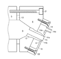
- FIG. 1 is a vertical sectional view showing a configuration example in a state in which a resin extrusion die according to an embodiment of the present invention is attached to an extrusion apparatus.
- a resin extrusion die (hereinafter simply referred to as a die) includes a base 8 attached to the die holder 5 of the extrusion device by, for example, a screw 21 and a cover 10 attached to the base 8 by, for example, a screw 22.
- the base 8 is provided with a discharge nozzle 12 having a discharge hole 15, and the molten resin supplied by a screw (not shown) to the flow path 9 provided in the die holder 5 is extruded from the discharge hole 15 in a strand shape. It is.
- the O-ring-shaped packing 13 is provided to block the gap between the die holder 5 and the die 8 and prevent high-pressure molten resin from leaking from the attachment portion between the die 8 and the die holder 5.
- FIG. 1 is a vertical sectional view, only one discharge nozzle 12 is shown, but a plurality of discharge nozzles 12 may be arranged at predetermined intervals in a direction orthogonal to the paper surface. Further, in the following description, the lower direction of FIG. 1 is vertically downward, and the resin is extruded slightly downward from the horizontal direction. However, in the die according to the present embodiment, there is no restriction on the resin extrusion direction. The die attachment angle and / or the direction of the discharge nozzle 12 can be arbitrarily changed.
- the cover 10 is attached to the base 8 so as to form a space with the base 8. Further, a gas inlet 14 for introducing gas into the cover 10 from a gas supply unit (not shown) is provided in the upper front portion of the cover 10, and the gas is supplied through a gas supply nozzle 14 a attached to the gas inlet 14. It is introduced into the cover 10 from the supply unit.
- a gas inlet 14 for introducing gas into the cover 10 from a gas supply unit is provided in the upper front portion of the cover 10, and the gas is supplied through a gas supply nozzle 14 a attached to the gas inlet 14. It is introduced into the cover 10 from the supply unit.
- the gas inlet 14 may not be provided in the cover 10.
- the cover 10 is also provided with gas outlets 11 corresponding to the individual discharge nozzles 12.
- the gas outlet 11 is provided to allow the gas supplied from the gas supply port 14 to the space inside the cover 10 to flow out from the periphery 11 a and 11 b around the tip of the discharge nozzle 12.
- the inner wall 10 a around the gas outlet 11 of the cover 10 is tapered in a mortar shape toward the gas outlet 11 so as to gradually narrow the gas flow path toward the gas outlet 11.
- the cover 10 may be configured to cover at least a part of the base 8 so that the gas supplied from the gas supply port 14 can flow out only from the gas outlet 11.
- the gas outlet 11 of this embodiment makes the flow rate or flow rate distribution of the gas flowing out from the periphery of the discharge nozzle 12 non-uniform due to its shape or positional relationship with the discharge nozzle 12, Use turbulent flow.
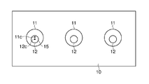
- FIG. 2 is a front view of the die of this embodiment when the nozzle is viewed from the front in the resin extrusion direction.
- the die base 8 has three discharge nozzles 12 and three gas outflow holes 11 corresponding to the discharge nozzles 12 are provided in the cover 10.
- the gas outlet 11 has a circular shape having a diameter larger than the outer diameter of the tip of the discharge nozzle 12. Further, the gas outlet 11 forms a gap around the tip of the discharge nozzle 12 and is a gas outlet with respect to the center 12c of the discharge nozzle 12 (discharge hole 15) whose section perpendicular to the resin extrusion direction is circular. 11 has a positional relationship such that the center 11c is biased upward. By setting the gas outlet 11 and the discharge nozzle 12 in such a positional relationship, the width of the gap formed around the tip of the discharge nozzle 12 by the gas outlet 11 can be made non-uniform.
- the gas flowing out from the gap becomes a turbulent flow, and the eyes and the eyes accumulated at the tip of the discharge nozzle 12 are easily blown away.
- the air flow becomes turbulent, the small eyes generated around the discharge holes 15 vibrate and are blown off at an early stage (at the stage of minute objects).
- the blown-off eyes are small and, of course, the deterioration is not progressing, so even if they adhere to the surface of the strand extruded from the discharge nozzle 12, they are diffused and diluted on the surface of the strand and are clearly recognized as foreign matter. It is not in a state to be able to
- FIG. 2 shows an example in which the center 11c of the gas outlet 11 is biased upward with respect to the center 12c of the discharge nozzle 12, but not only in the upward direction but also in any direction from the center 12c of the discharge nozzle 12. Can be made.
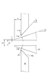
- FIG. 3 is a vertical sectional view for explaining the positional relationship between the discharge nozzle 12 and the gas outlet 11 in FIG. 2 in more detail.
- the width of the gap between the gas outlet 11 and the outer periphery of the tip of the discharge nozzle 12 is not uniform, and in the example of FIG.
- the maximum gap width is dmax and the narrowest gap width is dmin, so that the lower limit of dmax / dmin (> 1.0).
- the upper limit value of dmax / dmin is preferably 2.0 or less, and more preferably less than 1.5.
- dmin is preferably at least 0.1 mm or more.
- the inner diameter ⁇ d of the discharge nozzle 12 is preferably 7 mm ⁇ ⁇ d ⁇ 2 mm. If it is larger than 7 mm, the strand becomes too thick, and it is easy to cut at the time of take-up, and the productivity is lowered. On the other hand, if it is smaller than 2 mm, the pressure in the die becomes too high, and it becomes easy to vent up.
- the tip of the discharge nozzle 12 is tapered so as to reduce the wall thickness.
- Lt (outer diameter ⁇ D ⁇ inner diameter ⁇ d) / 2 is desirably small as long as the strength can be maintained.
- ⁇ ⁇ is preferable.
- ⁇ - ⁇ is preferably 0.5 ° or more, more preferably 1.0 or more, and most preferably 3.0 or more.
- ⁇ - ⁇ is preferably 50 ° or less. If it exceeds 50 °, the air velocity at the tip of the nozzle is decreased, and the effect of removing the eye corners is reduced.
- the flow rate of the gas flowing out from each gas outlet 11 is preferably 5 to 100 liters / minute (5 to 100 liters / minute). If it is less than 5 liters / minute, the flow rate becomes insufficient, and the effect of suppressing adhesion to the eyes cannot be obtained sufficiently. Moreover, when it exceeds 100 liters / minute, the influence with respect to the extruded resin may arise, such as a resin strand being cut
- gas is supplied so that the linear velocity of the airflow flowing out from each gas outlet 11 is 4 to 100 m / sec.
- the linear velocity is less than 4 m / sec, the wind pressure becomes insufficient, and the effect of suppressing the deposition on the eyes cannot be obtained sufficiently.
- it exceeds 100 m / sec the influence with respect to extruded resin may arise, such as a resin strand being cut
- the gas temperature varies depending on the type of resin to be extruded, the softening point, the melting temperature, etc., but if it is an amorphous resin, it is heated from (Tg (glass transition temperature) -100) ° C. to (Tg + 50) ° C. It is preferable that For example, when polycarbonate is used as the resin, the temperature is preferably about 50 ° C. to 200 ° C. In the case of a crystalline resin, it is preferably heated to (Tm (melting temperature) ⁇ 150) ° C. to Tm ° C. For example, when polybutylene terephthalate is used as the resin, the temperature is preferably about 70 to 220 ° C.
- the amorphous resin is heated to a temperature of (Tg ⁇ 70) ° C. to (Tg + 30) ° C., and that of the crystalline resin is (Tm ⁇ 120) ° C. to Tm ° C.
- Tg ⁇ 70 a temperature of (Tg ⁇ 70) ° C. to (Tg + 30) ° C.
- the crystalline resin is (Tm ⁇ 120) ° C. to Tm ° C.
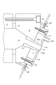
- the positional relationship between the gas outlet 11 and the discharge nozzle 12 can be adjusted.
- the diameter of the screw 22 is made smaller than the diameter of the hole of the cover 10, and the threaded portion of the screw 22 is separated from the hole of the cover 10. That is, the cover 10 is fixed at the plate portion of the screw 22. Thereby, in the state where the screw 22 is not tightened, the cover 10 can move slightly.
- the cover 10 is moved relative to the base 8 in the vertical direction and positioned, and then the screw 22 is tightened.
- the cover 10 is fixed.
- the configuration in FIG. 4 is an example of a configuration in which the relative positional relationship between the gas outlet 11 and the discharge nozzle 12 can be adjusted, and any other configuration can be adopted. Further, the adjustment may be made not only in the vertical direction but also in the horizontal direction.
- the essence of the present invention is that the gas flowing out from the gap formed around the tip of the discharge nozzle 12 by the gas outlet 11 is not uniform in at least one of local and temporal distribution of flow velocity and flow rate. It is to prevent turbulent flow and accumulation in the eyes. Further, by changing the direction of airflow resistance applied to the deposited eyes by time due to the turbulent flow of the gas, even if the eyes are deposited, they are easily removed.
- the center 11c of the circular gas outlet 11 is offset from the center 12c of the discharge nozzle 12 (discharge hole 15) having a circular cross section perpendicular to the resin extrusion direction, whereby the discharge nozzle 12 is discharged by the gas outlet 11.
- discharge hole 15 discharge hole 15 having a circular cross section perpendicular to the resin extrusion direction
- 5A to 5D schematically show examples of the shape of the gas outlet 11 for making the flow velocity or flow rate distribution of the gas flowing out from the gap around the tip of the discharge nozzle 12 non-uniform.
- FIG. 5A shows an ellipse
- FIG. 5B shows a square
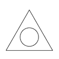
- FIG. 5C shows an equilateral triangle
- FIG. 5D shows a shape in which the distance from the center changes periodically.
- FIG. 5D shows a shape in which the distance from the center changes periodically.
- the process which irregularly roughens the gas outlet 11 formed circularly can also be performed by developing FIG. 5D.
- the gas outlet 11 is circular and the outer shape of the discharge nozzle 12 is non-circular.
- FIG. 6A is a vertical cross-sectional view of the main part showing a configuration example of the cover 10 provided with a current plate.
- FIG. 6A shows a state in which the cover 100 is viewed from the extruder (from the space formed between the die base 8 and the cover 10).
- a space between the gas supply port 14 and the gas outlet 11 is widely formed, and a rectifying plate 31 that guides gas from the gas supply port 14 to each of the gas outlets 11 is provided. Yes.
- the main role of the rectifying plate 31 is to supply a sufficient amount of gas to the gas outlet 11 located far away.
- the cover 10 is attached to the base 8, depending on the position where the rectifying plate 31 is provided.
- gas is blown obliquely from above to each discharge nozzle 12 to form an airflow (swirl flow, spiral flow) that is swirled around the resin extrusion direction.
- the direction of the gas flowing out from the gas outlet 11 includes components in more various directions.
- it is possible to realize an effect of making it difficult to adhere to the surface of the strand by controlling the direction in which the eyes are blown away from the direction in which the resin is extruded.
- FIG. 6B is a diagram illustrating an example of airflow control protrusions provided on the inner wall 10 a formed in a tapered shape around the gas outlet 11 in the cover 10.
- each of the plurality of control protrusions 32 has an inner wall 10 a that urges the gas flow toward the gas outlet 11 to vortex counterclockwise with respect to the center of the gas outlet 11. Is provided.
- the gas flowing out from the gas outlet 11 can be an airflow swirling counterclockwise around the discharge nozzle 12, coupled with the effect of the positional relationship between the gas outlet 11 and the discharge nozzle 12.
- it is possible to realize an effect of making it difficult to adhere to the surface of the strand by controlling the direction in which the eyes are blown away from the direction in which the resin is extruded.
- FIG. 7 is a diagram showing a configuration in which the gap between the gas outlet 11 and the discharge nozzle 12 tip is dynamically changed by vibrating the cover 10 up and down.
- a vibration generator 30 that vibrates the base 8 is provided.
- the vibration generator 30 has a vibration member (not shown) such as an actuator, and the operation of the actuator is controlled by a control circuit (not shown).
- the vibration generator 30 can vibrate the base 8 (and the cover 10 attached to the base 8) in a vertical direction or a horizontal direction at a predetermined frequency and amplitude.
- the vibration applied to the base 8 preferably has an amplitude of 0.005 mm to 0.2 mm and a vibration speed of 0.3 mm / second to 5 mm / second. More preferably, the amplitude is 0.009 mm to 0.1 mm, a more preferable vibration speed is 0.4 mm / second to 4 mm / second, and a particularly preferable vibration speed is 0.5 mm / second to 3 mm / second.
- the vibration frequency (Hz) can be obtained by vibration speed (mm / s) / (2 ⁇ ⁇ amplitude (mm)).
- Exceeding the upper limit of the amplitude and vibration speed may cause the extruded strands to vibrate greatly, and the strands extruded from the adjacent discharge holes may collide or the contact between the strands and the cooling water may become unstable. Can not be manufactured.
- the screws 21 and 22 for fixing the base 8 and the cover 10 may be loosened, which may cause a stable production. On the other hand, if it is less than the lower limit, the effect of turbulent airflow due to vibration cannot be obtained sufficiently.
- the configuration shown in FIG. 7 is an example of a configuration for turbulent airflow flowing out from the gas outlet 11, and it goes without saying that other configurations can be adopted.
- the base 8 (and the cover 10) may be vibrated using the vibration generated by the motor of the extruder without providing an active vibration member such as the actuator 135.
- the gap formed by the gas outlet 11 around the tip of the discharge nozzle 12 is constant in a state where no vibration is applied, as in the prior art.
- the positional relationship can be such that the width (the center is not biased) is obtained. This is because the tip of the discharge nozzle 12 shakes due to vibration, and the center of the discharge nozzle is substantially deviated from the center position of the gas outlet 11.
- the configuration for vibrating the base 8 (and the cover 10) is such that the shape of the gas outlet 11 is changed as shown in FIGS. 5A to 5D, or a rectifying plate is formed as shown in FIGS.
- the gas used by this invention is not limited to air, Inert gas, nitrogen, and water vapor
- the specific structure is (1) In order to equalize the inner diameter ⁇ d (cross-sectional area orthogonal to the extrusion direction) of the plurality of discharge nozzles and the pressure of the molten resin supplied to the plurality of discharge nozzles, the rear part of the discharge nozzle (extruder side) The relationship with the cross-sectional area of the manifold 120 provided in (a cross-sectional area perpendicular to the extrusion direction) satisfies a specific relationship, and (2) The length of the discharge nozzle satisfies a specific condition, Structure.
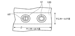
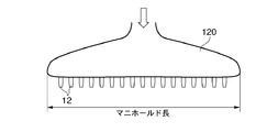
- FIG. 8A is a front view of two of the plurality of discharge nozzles 12, and FIG. 8B is a vertical cross-sectional view of a certain discharge nozzle 12 (vertical cross-sectional view including an axis when the discharge nozzle is regarded as a cylindrical shape). is there.
- a manifold 120 for supplying molten resin with a uniform pressure to the plurality of discharge nozzles 12 is usually provided at the rear of the plurality of discharge nozzles 12. All the discharge nozzles 12 are supplied with molten resin through a common manifold 120.
- the molten resin supplied to the die from the extruder once stays in the manifold 120, the pressure is made uniform, and the extrusion amount from the discharge nozzle 12 becomes uniform by being squeezed by the thin discharge nozzle 12.
- the narrowing rate at the discharge nozzle 12 is too small (if it is not narrowed too much)
- the pressure applied to each discharge nozzle 12 becomes uneven, the strands are not stable, the strands break, and the eyes on the discharge nozzles 12 adhere to the eyes.
- the squeezing rate is too large, the resin pressure becomes high, the resin filling region at the screw tip of the extruder becomes long, heat is generated by shearing, the resin temperature rises, and there is a lot of generation in the eyes.
- the pressure applied to the discharge nozzles 12 is not uniform, the strands are not stable, the strands break, and the eyes and the adherence to the discharge nozzles 12 increase.
- the length is too long, the resin temperature rises and the generation of the eyes increases. Therefore, the balance between the narrowing rate and the length of the discharge nozzle 12 has a great influence on the stability of the strands and, in turn, on the eyes.
- the diameter of the manifold 120 is the diameter shown in FIG. 8B, that is, the maximum projected vertical distance when the discharge nozzle 12 is viewed from the front. Is the longitudinal distance including, as shown in FIG. 8C.
- FIG. 8C only the manifold 120 and the discharge nozzle are extracted and schematically shown so that the shape of the manifold 120, which is a cavity formed in the die, can be seen.
- the throttle ratio which is the ratio S1 / S2 between the total area S1 of the minimum sectional area of the discharge nozzle 12 and the maximum area S2 of the manifold 120 defined as described above, is 10% ⁇ S1 / S2 ⁇ 1.2%, preferably 8 % ⁇ S1 / S2 ⁇ 2%.
- the discharge nozzle 12 has a length of 15 to 50 mm, more preferably 18 to 40 mm.
- the discharge nozzle 12 generally has a structure having a cross section as shown in FIG. 8B, the inner diameter of the discharge nozzle 12 refers to the minimum diameter portion of the tip of the discharge nozzle 12, and has a root having a larger shape. It is not the diameter of the part (manifold 120 side). However, the length of the discharge nozzle 12 is not the length of only the minimum diameter portion but the length of the entire portion protruding from the manifold 120.
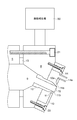
- FIG. 9A is a diagram schematically illustrating a configuration related to a process until the strand extruded from the discharge nozzle 12 is processed into a pellet shape.
- the strand 91 is taken up by the take-up roller 95 and processed (cut) into a pellet form by the pelletizer 96, but is usually cooled in the transport path before being supplied to the pelletizer 96.
- the cooling medium usually water
- the cooling medium 93 stored in the cooling tank 92 is conveyed and cooled.
- the time from when the strand 91 is pushed out of the discharge nozzle 12 until it enters the cooling medium 93 is shorter. Normally, it is preferable to enter the cooling medium 93 within one second after being pushed out from the discharge nozzle 12.
- guide rollers such as 94A and 94B are generally provided in the transport path of the strand 91.
- the diameter of the guide rollers 94A and 94B is usually about 3 to 7 cm.
- At least one of the guide rollers 94A and 94B is rotated in the direction opposite to the traveling (conveying) direction of the strand 91, or at a peripheral speed slower than the traveling speed (take-off speed) of the strand 91. Is rotated in the same direction as the traveling direction (or may be held without being rotated).
- the guide rollers 94A and 94B usually have a cylindrical shape with a direction intersecting the traveling direction of the strand as a rotation axis, and a plurality of strands 91 that are extruded in parallel so that the strands 91 are conveyed along a desired conveyance path. Support with a cylindrical surface.
- a plurality of annular (ring-shaped) grooves 942 are provided in the circumferential direction on the cylindrical surfaces of the guide rollers 94A and 94B. The groove 942 receives and supports the traveling strand 91, and prevents the strands 91 located in close proximity from coming into contact with each other and fused.
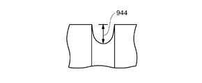
- the width of the groove 942 is slightly larger than the thickness of the strand 91, and the bottom of the groove 942 is preferably arcuate for stable support.
- the depth of the normal groove 942 is 2 mm to 10 mm, although it depends on the diameter of the strand 91.
- the pitch of the grooves 942 (the interval between adjacent grooves 942) is usually matched to the interval between the strands 91 (the interval between the discharge nozzles 12 of the die). Depending on the diameter of the strand 91, the pitch is 5 mm to 20 mm.
- the number of grooves 942 may be more than the number of strands to be extruded.
- One or a plurality of guide rollers 94A, 94B are provided at the strand travel position of the cooling tank 92. In the case of a plurality of pieces, a strand is stretched between the guide rollers 94A and 94B, travels through the cooling tank 92, and is cooled.
- the guide rollers 94A and 94B may be supported so as to be rotatable in the direction opposite to the running direction of the strands or in the same direction as the running direction, or may be supported so as not to rotate.
- the guide rollers 94A and 94B By supporting the guide rollers 94A and 94B so that the moving (rotating) speed of the grooves 942 of the guide rollers 94A and 94B is relatively slow with respect to the traveling (conveying) speed of the strand 91, the grooves 942 and the strands 91 and The surface of the strand 91 can be rubbed with the surface in contact with the surface, and the eye attached to the surface of the strand 91 can be rubbed off.
- at least one of the guide rollers 94 may be rubbed on the surface of the strand 91.
- a drive device may be provided on the guide rollers 94A and 94B.
- the rotation amount is determined within a range in which the running of the strand 91 is stable.
- the driving device may not be provided. It is only necessary to give a certain amount of resistance to rotate the guide rollers 94A and 94B (at least resistance that prevents the strand 91 from rotating at the speed due to the frictional force of the traveling strand 91). As a result, the guide rollers 94A and 94B rotate following the travel of the strand 91. However, due to the applied resistance, the guide rollers 94A and 94B rotate slower than the travel speed of the strand 91 (peripheral speed is slow). It becomes possible to rub. Although it is possible to provide a drive device, unlike the case of reverse rotation, a configuration that provides resistance to rotation is simpler.
- the strand 91 contacts the surfaces of the guide rollers 94A and 94B while traveling in the cooling medium 92, and the strand 91 is caused by the difference between the traveling speed of the strand 91 and the rotation speed (circumferential speed) of the guide rollers 94A and 94B.
- the surface of the groove 942 is rubbed with the surface of the groove 942, and the eye and the eye attached to the surface of the strand 91 are removed.
- the specific rotation (circumferential) speed Vr of the guide rollers 94A and 94B is preferably in a relation of 0.7 ⁇ Vr / Vs ⁇ ⁇ 0.2 with respect to the strand speed Vs.
- the upper limit is more preferably 0.5 ⁇ Vr / Vs, and the lower limit is more preferably Vr / Vs ⁇ 0.
- Vs can be the take-up speed of the strand 91, and Vr is obtained by (radius of guide rollers 94A, 94B ⁇ groove depth) ⁇ 2 ⁇ ⁇ number of rotations per minute.
- Vr / Vs is positive, the guide rollers 94A and 94B rotate in the same direction as the strand travel direction.
- the guide rollers 94A and 94B rotate in the direction opposite to the strand travel direction.
- One or a plurality of guide rollers 94A and 94B are provided in the cooling tank. In the case of a plurality of guide rollers 94A and 94B, it is not necessary to rotate all of the guide rollers 94A and 94B as described above, and the guide rollers 94A and 94B are in the cooling medium 93. It is effective to remove the guide roller (94A in FIG. 9A) closest to the discharge nozzle 12 (die) as described above.
- the molten resin may be a single component of a thermoplastic resin such as polycarbonate, polybutylene terephthalate, polyamide, polyphenylene ether, polyacetal, or a mixture of a plurality of thermoplastic resins.
- a reinforcing filler can be blended in the molten resin.
- Non-limiting examples of reinforcing fillers include glass fibers, carbon fibers, silica / alumina fibers, zirconia fibers, boron fibers, boron nitride fibers, silicon nitride potassium titanate fibers, metal fibers and other inorganic fibers, aromatics Examples thereof include organic fibers such as polyamide fibers and fluororesin fibers. These reinforcing fillers can be used in combination of two or more.
- Other fillers can be blended with the molten resin together with or separately from the reinforcing filler.
- Non-limiting examples of other fillers include plate-like inorganic fillers, ceramic beads, asbestos, wollastonite, talc, clay, mica, zeolite, kaolin, potassium titanate, barium sulfate, titanium oxide, silicon oxide , Aluminum oxide, magnesium hydroxide and the like.
- the anisotropy and warpage of the molded product can be reduced by blending the plate-like inorganic filler.
- the plate-like inorganic filler include glass flakes, mica, metal foil and the like. Among these, glass flakes are preferably used.
- phenol compounds such as 2,6-di-t-butyl-4-octylphenol, pentaerythrityl-tetrakis [3- (3 ′, 5′-t-butyl-4′-hydroxyphenyl) propionate], dilauryl- Thioether compounds such as 3,3′-thiodipropionate, pentaerythrityl-tetrakis (3-laurylthiodipropionate), triphenyl phosphite, tris (nonylphenyl) phosphite, tris (2,4-di- Antioxidants such as phosphorus compounds such as t-butylphenyl) phosphite, paraffin wax, microcrystalline wax, polyethylene wax, long-chain fatty acids typified by montanic acid and montanic acid esters, and mold release of silicone oil An agent or the like may be added to the molten resin.
- dilauryl- Thioether compounds such as 3,3
- a flame retardant can be blended to impart flame retardancy to the resin.
- flame retardants include organic halogen compounds, antimony compounds, phosphorus compounds, other organic flame retardants, inorganic flame retardants, and the like.
- organic halogen compound include brominated polycarbonate, brominated epoxy resin, brominated phenoxy resin, brominated polyphenylene ether resin, brominated polystyrene resin, brominated bisphenol A, and pentabromobenzyl polyacrylate.
- the antimony compound include antimony trioxide, antimony pentoxide, sodium antimonate, and the like.
- phosphorus compound phosphate ester, polyphosphoric acid, ammonium polyphosphate, red phosphorus etc. are mentioned, for example.
- organic flame retardants include nitrogen compounds such as melamine and cyanuric acid.
- inorganic flame retardants include aluminum hydroxide, magnesium hydroxide, silicon compound, and boron compound.
- thermoplastic resins such as polyethylene, polypropylene, polystyrene, polyacrylonitrile, polymethacrylate, ABS resin, polycarbonate, polyamide, polyphenylene sulfide, polyethylene terephthalate, liquid crystal polyester, phenol resin, melamine resin, silicone Thermosetting resins such as resins and epoxy resins can be blended. These thermoplastic resins and thermosetting resins can also be used in combination of two or more.
- the resin extrusion die of the present invention can be applied to the extrusion of various molten resins.
- the molten resin is composed of a single component, there is little occurrence in the eyes.
- a molten resin composed of a single thermoplastic resin such as polycarbonate, polybutylene terephthalate, polyamide, polyphenylene ether, polyacetal, etc.
- thermoplastic resin when other components such as the above-mentioned reinforcing filler, filler, flame retardant, other thermoplastic resin, and thermosetting resin are added to the molten resin of these thermoplastic resins, the occurrence of the eye is noticeable.
- these other components are contained in the molten resin in an amount of 5% or more, the generation of the eyes is increased, and when the content is 10% or more, the generation of the eyes becomes remarkable. Therefore, by using the resin extrusion die of the present invention for extrusion of a molten resin containing 5% or more of other components, it is possible to enjoy a remarkable effect of suppressing generation and contamination in the eyes.
- the release agent When the release agent is added in an amount of 0.03% or more based on the molten resin, an inhibitory effect appears in the eye. In particular, when an amount of 0.1% or more is added, the inhibitory effect becomes remarkable. On the other hand, even if it is added at a ratio exceeding 1%, the improvement in the effect is small, so that it is preferably made 1% or less from the viewpoint of cost.
- a ballast effect also called a die swell
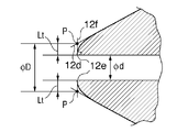
- the end surface 12b that is formed at the tip 12a of the discharge nozzle 12 and is substantially perpendicular to the resin extrusion direction becomes large.
- the gas flowing out from the gas outlet 11 around the discharge nozzle 12 travels along the outer periphery of the discharge nozzle 12, and then flows into an air flow a1 toward the extruded molten resin and an air flow a2 that vortexes behind the end surface 12b.
- a region 12c where the spiral airflow a2 does not reach is generated, so that it is considered that the eyes easily adhere to the region 12c.
- the thickness Lt of the tip 12a of the discharge nozzle 12 is preferably small, and specifically, 0 ⁇ thickness Lt ⁇ 2 mm is preferable.
- the wall thickness Lt exceeds 2 mm, it is difficult to sufficiently obtain the effect of blowing the gas to the outer periphery in the vicinity of the tip of the discharge nozzle 12 for the reason described above.
- the shape of the tip portion 12a of the discharge nozzle 12 can be processed.
- the fact that the end face 12b is substantially 0 mm means that the thickness Lt is about 0.05 mm or less.
- a surface substantially perpendicular to the resin extrusion direction can be substantially eliminated.
- this radius may be a so-called “chamfered” shape that is not a curve. In the case of the shape of FIG.
- the wall thickness Lt is preferably as close to 0 as possible. However, since deformation or loss of the tip 12a may be a fatal defect, the wall thickness Lt is about 0.03 mm or more when the structure of FIG. 10A is adopted. It is considered good to do.
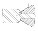
- FIG. 10C shows another processing example for reducing the end face 12b substantially perpendicular to the resin extrusion direction.
- a portion corresponding to the end surface 12b is processed into a curved mortar shape toward the center of the nozzle.
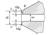
- ⁇ D that defines the wall thickness Lt can be defined as the distance between the two most distal points 12 g of the tip end portion 12 a in the vertical cross section along the central axis in the longitudinal direction of the discharge nozzle 12.
- ⁇ D can be defined as the maximum interval between the two most advanced points (interval of 12g ′).
- a round (arrow R) is formed on the inner surface of the nozzle tip, and this rounding promotes smooth expansion (expansion / expansion due to the ballast effect) of the resin, and prevents accumulation in the eyes. It helps a lot.
- the size of the radius (the radius defining the radius) is suitably about 0.005 to 1 mm. In the case of so-called chamfering in which the rounded surface is a flat surface, a suitable surface width is about 0.005 to 1 mm.
- the components of the thermoplastic resin composition that is extruded into a strand shape are not particularly limited.
- the temperature is 280 ° C.
- the shear rate is 100 / second.
- the shear viscosity measured under the conditions is preferably 50 Pa ⁇ sec or more and 5000 Pa ⁇ sec or less. More preferably, the shear viscosity measured under the same conditions is 80 Pa ⁇ sec or more and 3000 Pa ⁇ sec or less.
- the shear viscosity is less than 50 Pa ⁇ sec, the viscosity is low and the ballast effect is reduced, and therefore, the effect of suppressing deposition on the eyes cannot be sufficiently obtained even by controlling the discharge amount described later.
- ballast effect is made extreme by rubbing the substantially vertical end surface 12b of the nozzle tip 12a with the surface of the strand, and immediately adheres to the surface of the strand and moves before it is deteriorated. In addition, accumulation on the eyes and on the nozzle tip 12a is suppressed.
- discharge rate By controlling the discharge amount of the molten resin (composition), the increase in diameter (die swell ratio) due to the ballast effect is controlled, and the air flow along the outer periphery of the discharge nozzle 12 from the gas outlet 11 becomes an expanded portion of the strand. The direction of the airflow is changed by allowing it to be blown. Thereby, it is possible to further suppress the deposition on the eyes by causing the gas to strike the portion where the molten resin composition is separated from the discharge nozzle (the portion where the eyes and the eye are liable to generate) with a sufficient wind pressure. It should be noted that the effect of suppressing the deposition on the eyes is achieved not only by suppressing the generation of the eyes itself, but also by blowing off the generated eyes and eyes in a minute stage.
- the lower limit of the discharge amount of the molten resin (composition) from the discharge nozzle is 14 kg / hour or more, preferably 17 kg / hour or more, more preferably 19 kg / hour or more, and the upper limit is 40 kg / hour.
- the amount is less than 30 hours, preferably 30 kg / hour or less, more preferably 24 kg / hour or less, the above-described thermoplastic resin (composition) having the shear viscosity can have a good ballast effect, and it can be easily observed. It has been found that it is possible to prevent contamination.
- the expanded portion of the resin strand is present as a wall when viewed from the air flow a, particularly the component flowing along the outer peripheral surface of the discharge nozzle 12 from the gas outlet 11. Therefore, the airflow hits the expansion portion and changes its direction, and the gas pressure acts on the portion where the strands are separated from the discharge nozzle 12 and in the vicinity thereof, that is, the portion where the eye easily occurs. It is considered that the deposition suppressing effect is effectively realized.
- the discharge amount is less than 14 kg / hour or exceeds 40 kg / hour, the effect of preventing the eyes and the eyes from being mixed into the resin product cannot be sufficiently obtained.
- the discharge nozzle 12 is provided with two or more in the nozzle
- the discharge amount here is a discharge amount per discharge nozzle.
- the die swell ratio is preferably 1.35 or less. In order to set the die swell ratio to a value exceeding 1.35, it is necessary to increase the discharge amount, which becomes a factor that easily causes eyes and eyes.
- the die swell ratio is more preferably 1.30 or less.
- the die swell ratio is determined by taking a photograph of the resin strand being molded and the nozzle tip (inner diameter) in the unmolded state from the same position, and calculating the maximum strand diameter ( ⁇ D) and nozzle inner diameter ( ⁇ d) within 2 cm from the nozzle tip. The actual ratio from the photograph ( ⁇ D / ⁇ d) was taken as the die swell ratio.
- Example 1 Resin extrusion dies as shown in FIGS. 1 to 3 were produced using die steel SKD11.
- the resin is a resin composition (resin composition A) containing 30% by weight of glass fiber (FT737 manufactured by Owen Corning) and 70% by weight of polycarbonate (Iupilon S3000 manufactured by Mitsubishi Engineering Plastics) at a temperature of 280 ° C.
- the shear viscosity at a shear rate of 100 / sec was 1300 Pa ⁇ sec).
- Extrusion was performed at a preset temperature of 250 ° C. of the extruder cylinder and resin extrusion die.
- the resin temperature is usually considered to be about 30 ° C. higher than the set temperature of the die.
- the air heated to 150 degreeC was supplied from the gas supply port 14 so that the flow volume from each gas outflow port might be 10 liter / min in conversion of room temperature.
- the resin is a resin composition (resin composition B) containing 30% by weight of glass fibers (183H-13P manufactured by Owens Corning) and 70% by weight of polybutylene terephthalate (Novalex 5008 manufactured by Mitsubishi Engineering Plastics). Except that the shear viscosity at a temperature of 280 ° C. and a shear rate of 100 / sec was 340 Pa ⁇ sec), the resin was extruded under the same conditions as in Example 1. Of the continuous extrusion for 3 hours, minute eyes and eyes were observed from 2 hours after the start, but they were blown away in the state of minute objects and did not accumulate greatly.
- the resin is a resin composition (resin composition C) containing 30% by weight of glass fiber (T-249H manufactured by Nippon Electric Glass Co., Ltd.) and 70% by weight of polyamide (Novamid 1010J manufactured by Mitsubishi Engineering Plastics Co., Ltd.).
- the resin was extruded under the same conditions as in Example 1 except that the shear viscosity at a shear rate of 100 / sec was 370 Pa ⁇ sec. Of the continuous extrusion for 3 hours, minute eyes and eyes were observed from 2 hours after the start, but they were blown away in the state of minute objects and did not accumulate greatly.
- Example 5 Extrusion was performed in the same manner as in Example 1, except that the flow rate from each gas outlet was 4 liters / minute in terms of room temperature. Of the extrusion continued for 3 hours, a slight eye was observed at the tip of the discharge nozzle after 1 hour, but no foreign matter was mixed into the molded product. Further, after 3 hours, a slight eye adhered to the tips of the three discharge nozzles was collected and the weight was measured to be 4 mg.
- Example 7 A small electrodynamic vibration test device (Wave Maker 01, manufactured by Asahi Seisakusho Co., Ltd.) is attached to the die portion of the resin extrusion die as the vibration generator 30 shown in FIG. Except that was added, the resin composition A was extruded under the same conditions as in Example 1.
- a pocketable vibrometer VM-63A “RIOVIBRO” manufactured by RION Co., Ltd. was pressed against the base, and the amount of vibration and vibration speed of the base were measured. As a result, the amplitude was 0.01 mm and the vibration speed was 1.0 mm / sec. Extrusion was continued for 3 hours, but no generation of eyes or contamination of foreign matter (modified resin composition A) was detected.
- Example 3 A full-scale electrodynamic vibration test device (Big Wave manufactured by Asahi Seisakusho Co., Ltd.) is attached to the die portion of the resin extrusion die as the vibration generator 30 shown in FIG. 7, and the vibration is 20 Hz in the vertical direction and 50% output. Except that was added, the resin composition A was extruded under the same conditions as in Example 1. When the amplitude and vibration speed of the die were measured in the same manner as in Example 7, the amplitude was 0.3 mm and the vibration speed was 35 mm / second.
- Example 8 Resin under the same conditions as in Example 1 except that 0.3% by weight release agent (Mitsui Petrochemical Industries, Ltd., HW100P, low molecular weight polyethylene) was added to resin composition A, 99.7% by weight. Extrusion of composition A was performed. Extrusion was continued for 3 hours, but no generation of eyes or contamination of foreign matter (modified resin composition A) was detected.
- 0.3% by weight release agent Mitsubishi Petrochemical Industries, Ltd., HW100P, low molecular weight polyethylene
- Example 9 Resin composition A was used, and a die for resin extrusion as shown in FIGS. 1 to 3 was produced using die steel SKD11.
- three discharge nozzles 12 having a length of 25 mm were provided, and the maximum cross-sectional area of the manifold was 670 mm 2 (nozzle opening ratio was 3.2%). Further, air heated to 150 ° C.
- the resin was extruded by setting the resin discharge amount per discharge nozzle to 16.7 kg / hr. Further, when the pocketable vibrometer VM-63A “RIVIBRO” manufactured by RION Corporation was pressed against the base and the vibration amount and vibration speed of the base were measured, the amplitude was 0.008 mm and the vibration speed was 0.42 mm / sec. .
- the strand from the discharge nozzle was supplied to the pelletizer in a cooling and take-up configuration as shown in FIGS. 9A-9C to obtain a resin composition A (pellet).
- the strand take-up speed (Vs) was set to 35 m / min.
- Two guide rollers having a diameter of 40 mm, a groove depth of 7.5 mm, and a groove pitch of 9 mm were used.
- the guide roller 94A in the cooling tank close to the die was made rotatable, and the other guide roller 94B was fixed so as not to rotate.
- the resin was extruded under the same conditions as those described above.
- the diameter increase rate (die swell ratio) D / ⁇ d 1.08 due to the ballast effect. Extrusion was carried out continuously for 3 hours. Although minute eyes and eyes could be observed from about 2 hours after the start of molding, they were blown away in a minute state and did not accumulate significantly.
- the resin was extruded under the same conditions as those described above.
- the diameter increase rate (die swell ratio) D / ⁇ d 1.09 due to the ballast effect. Extrusion was carried out continuously for 3 hours. Although minute eyes and eyes could be observed from about 2 hours after the start of molding, they were blown away in a minute state and did not accumulate significantly.
- Example 19 A small electrodynamic vibration test device (Wave Maker 01, manufactured by Asahi Seisakusho Co., Ltd.) is attached to the die portion of the resin extrusion die as the vibration generator 30 shown in FIG. Except that was added, the resin was extruded under the same conditions as in Example 9.
- Example 22 Extrusion of the resin was carried out under the same conditions as in Example 19 except that a small electrodynamic vibration test apparatus (Wave Maker 01 manufactured by Asahi Seisakusho Co., Ltd.) was attached and vibrations of 20 Hz and 100% output were applied in the vertical direction.
- Extrusion was carried out continuously for 3 hours, but no generation of eyes or contamination with foreign matter (modified resin composition A) was detected. Therefore, when extrusion was continued for 3 hours and evaluation was performed up to 6 hours, no foreign matter was detected in the molded product (in this case, pellets) after 6 hours. In addition, after 6 hours, a small amount of eyes and eyes adhering to the periphery of the three discharge nozzles were collected, and the weight was measured to be only 1 mg.
- Example 23 Extrusion of the resin was carried out under the same conditions as in Example 20 except that the same vibration as in Example 22 was applied.
- the rate of increase in diameter (die swell rate) D / ⁇ d 1.18 due to the ballast effect.
- Extrusion was carried out continuously for 3 hours. Although minute eyes and eyes could be observed from about 1 hour after the start of molding, they were blown away in a minute state and did not accumulate significantly. Although some of the blown eyes seemed to adhere to the strands, no foreign matter (modified resin composition A) was detected in the molded product (in this case, pellets). It is thought that it was diffused and absorbed on the surface of the strand because it was in an eye that did not deteriorate. Further, after 3 hours, a slight eye adhered to the periphery of the three discharge nozzles was collected, and the weight was measured to be only 1 mg.
- Example 24 Extrusion of the resin was carried out under the same conditions as in Example 21 except that the same vibration as in Example 22 was applied.
- the rate of increase in diameter (die swell rate) D / ⁇ d 1.18 due to the ballast effect.
- Extrusion was carried out continuously for 3 hours. Although minute eyes and eyes could be observed from about 1 hour after the start of molding, they were blown away in a minute state and did not accumulate significantly. Although some of the blown eyes seemed to adhere to the strands, no foreign matter (modified resin composition A) was detected in the molded product (in this case, pellets). It is thought that it was diffused and absorbed on the surface of the strand because it was in an eye that did not deteriorate. Further, after 3 hours, a slight eye adhered to the periphery of the three discharge nozzles was collected, and the weight was measured to be only 1 mg.
- the diameter increase rate (die swell ratio) D / ⁇ d 1.17 due to the ballast effect.
- Extrusion was carried out continuously for 3 hours. Although minute eyes and eyes could be observed from about 1 hour after the start of molding, they were blown away in a minute state and did not accumulate significantly.
- One foreign object (modified resin composition A) was detected in the molded product (in this case, pellets). Further, after 3 hours, a slight eye adhered to the periphery of the three discharge nozzles was collected, and the weight was measured to be only 2 mg.
- Example 28> The same conditions as in Example 9 except that 0.3% by weight of a release agent (manufactured by Mitsui Petrochemical Co., Ltd., HW100P, low molecular weight polyethylene) is added to the resin composition A, 99.7% by weight.
- the resin was extruded.
- the diameter increase rate (die swell ratio) D / ⁇ d 1.17 due to the ballast effect.
- Extrusion was carried out continuously for 3 hours, but no generation of eyes or contamination with foreign matter (modified resin composition A) was detected. Therefore, when extrusion was continued for 3 hours and evaluation was performed up to 6 hours, no foreign matter was detected in the molded product (in this case, pellets) after 6 hours. In addition, after 6 hours, a small amount of eyes and eyes adhering to the periphery of the three discharge nozzles were collected, and the weight was measured to be only 1 mg.
- a release agent manufactured by Mitsui Petrochemical Co., Ltd., HW100P, low molecular
- modified resin composition A modified resin composition A
- the other conditions were the same as in Example 9, and the resin was extruded.
- the rate of increase in diameter (die swell ratio) D / ⁇ d 1.27 due to the ballast effect. Extrusion was carried out continuously for 3 hours.
- the resin that prevents gas from flowing out from the outer periphery of the discharge nozzle tip and deposits on the eye at the discharge nozzle tip and adhesion of the eye to the extruded resin is a turbulent flow in which at least one of the temporal distribution and the spatial distribution of the flow velocity or flow rate is not uniform.
- generation and deposition on the eyes can be further suppressed, and even if eyes and eyes are generated, they can be blown off in the state of minute objects at an early stage. Therefore, it is possible to continuously produce resin products with good quality.
Landscapes
- Engineering & Computer Science (AREA)
- Mechanical Engineering (AREA)
- Manufacturing & Machinery (AREA)
- Extrusion Moulding Of Plastics Or The Like (AREA)
- Processing And Handling Of Plastics And Other Materials For Molding In General (AREA)
Abstract
Description
また、乱流化により気流の方向は時間的に変化する。それにより吐出孔の縁から目やにを剥がす効果が増大したとも考えられる。
図1は、本発明の実施形態に係る樹脂押出用ダイを押出装置に取り付けた状態の構成例を示す垂直断面図である。
樹脂押出用ダイ(以下、単にダイという)は、押出装置のダイホルダ5に例えばネジ21によって取り付けられる口金8と、口金8に例えばネジ22で取り付けられるカバー10とから構成される。
上述の通り、気体流出口11と吐出ノズル12の先端部外周との間隙の幅は均一でなく、図2の例では鉛直上方における間隙が最も広く、鉛直下方における間隙が最も狭い。ここで、気体流出口11と吐出ノズル12の先端部外周との間隙のうち、最も広い間隙の幅をdmax、最も狭い間隙の幅をdminとすると、dmax/dminの下限値(>1.0)は1.05以上であることが好ましい。また、dmax/dminの上限値は2.0以下であることが好ましく、1.5未満であることがさらに好ましい。dmax/dminが1.05未満の場合、間隙の幅の差が小さく、間隙から流出する気体の流速又は流量の分布を不均一にする効果が十分に得られない。一方、dmax/dminが2.0を超えると、特にdminの値が小さくなった場合に、その部分の流速が不十分となり、目やにが付きやすく(堆積しやすく)なる。また、この点から、dminは、少なくとも0.1mm以上であることが好ましい。
なお、気体流出口11と吐出ノズル12との位置関係を調整可能に構成することも可能である。例えば、図4に示すように、ネジ22の径をカバー10の孔の径よりも小さくし、ネジ22のねじ切り部分はカバー10の孔とは離間した状態とする。つまり、ネジ22の皿部分で、カバー10を固定する構成とする。これにより、ネジ22が締め込まれていない状態では、カバー10がわずかに移動可能となる。ネジ22をわずかに緩めた状態でネジ24,25を調整することで、カバー10の位置を口金8に対して上下方向に相対的に移動して位置決めした後、ネジ22を締め込むことで、カバー10を固定する。
なお、図4の構成は気体流出口11と吐出ノズル12との相対的な位置関係を調整可能とした構成の一例であり、他の任意の構成を採用することができる。また、上下方向のみならず、左右方向においても調整可能としてもよい。
本発明の本質は、気体流出口11によって吐出ノズル12の先端部周囲に形成される間隙から流出する気体を、流速及び流量の少なくとも一方の分布が場所的及び時間的の少なくとも一方で不均一な乱流とし、目やにの堆積を抑制することである。また、気体の乱流化により、堆積した目やにが受ける気流抵抗の方向を時間的に変化させることにより、目やにが堆積しても、それが除去され易くすることである。
また、気体流出口11からの気体の流出方向をさらに積極的に制御する方法として、カバー10の内部に整流板を配置することも可能である。
図6Bは、カバー10において、気体流出口11周囲の、テーパー状に形成されている内壁10aに設けた気流の制御突起の例を示す図である。
図6Bにおいて、複数の制御突起32の各々は、気体流出口11へ向かう気体の流れを、気体流出口11の中心に対して反時計回り方向へ渦を巻くように付勢するように内壁10aに設けられている。このような構成により、気体流出口11から流出する気体を、吐出ノズル12の周囲で反時計回りに渦巻く気流とすることができ、気体流出口11と吐出ノズル12との位置関係による効果と相まって、目やにの堆積抑制、堆積した目やにの早期吹き飛ばしといった効果を一層高めることが可能になる。さらには、目やにが飛ばされる方向を樹脂の押出方向と異なる方向に制御し、ストランドの表面に付着しにくくする効果を実現することができる。
ここで、気体流出口11の形状や制御突起又は制御溝の形成といった構成は一方のみで充分であるが、組み合わせて採用することも可能である。
ここまでは気体流出口11と吐出ノズル12との位置関係が固定されている場合を想定して説明してきたが、位置関係を動的に変化させることで、間隙の大きさを動的に変化させてもよい。
図7は、カバー10を上下に振動させることにより、気体流出口11と吐出ノズル12先端部との間隙を動的に変化させる構成を示す図である。
図7に示す構成では、口金8を振動させる振動発生機30が設けられている。振動発生機30はアクチュエータのような振動部材(図示せず)を有し、図示しない制御回路によりアクチュエータの動作が制御される。振動発生機30はその動作状態において、口金8(及び口金8に取り付けられているカバー10)を所定の周波数及び振幅で上下方向、又は左右方向に振動させることができる。
なお、上述の構成を有する樹脂押出用ダイを用いて溶融樹脂をストランド状に成形する場合、複数の吐出ノズル12がダイに設けられるが、この吐出ノズルを特定の構造とすることにより押出が安定し、目やに防止(除去)やストランドの切断防止に有効である。
(1)複数設けられる吐出ノズルの内径φd(押出方向に直交する断面積)と、複数の吐出ノズルに供給される溶融樹脂の圧力を均一化するために、吐出ノズルの後部(押出機側)に設けられるマニホールド120の断面積(押し出し方向に直交する断面積)との関係が特定の関係を満たし、かつ、
(2)吐出ノズルの長さが特定の条件を満たす、
構造である。
従って、絞り込み率と吐出ノズル12長さのバランスはストランドの安定性、ひいては目やにの発生に大きく影響を与える。
このように定義される吐出ノズル12の最小断面積の合計面積S1とマニホールド120の最大面積S2との比率S1/S2である絞り率は10%≧S1/S2≧1.2%、好ましくは8%≧S1/S2≧2%程度である。
また、吐出ノズル12の長さは15~50mmであり、更に好ましくは18mm~40mmである。
絞り率S1/S2と吐出ノズル12の長さをこのようなバランスとすることにより、ストランドの安定した押出しが行え、ひいては目やに発生の抑制効果につながる。
ストランド91は引き取りローラー95によって引き取られ、ペレタイザー96によってペレット状に加工(切断)されるが、ペレタイザー96に供給される前の搬送経路において冷却されるのが通常である。具体的には図9Aに示すように、冷却槽92に溜められた冷却媒体(通常は水)93中を搬送されるようにして、冷却される。樹脂の劣化を少なくするために、ストランド91が吐出ノズル12から押し出されてから冷却媒体93に入るまでの時間は短い方が良い。通常は、吐出ノズル12から押し出されてから1秒以内に冷却媒体93に入るのが良い。
このような条件を満たす搬送経路を実現するため、ストランド91の搬送経路には94A,94Bで示すようなガイドローラーが設けられるのが一般的である。ガイドローラー94A,94Bの径は通常3~7cm程度である。
具体的には、ガイドローラー94A,94Bの少なくとも一方を、ストランド91の走行(搬送)方向とは逆方向に回転させるか、ストランド91の走行速度(引取り速度)よりも遅い周速度でストランド91の走行方向と同じ方向に回転させることである(あるいは、回転させない状態で保持してもよい)。
ガイドローラー94A,94Bの円筒面には図9Bに示すように周方向に環状(リング状)の溝942が複数設けられる。溝942は走行するストランド91を受け入れて支持し、接近した位置にあるストランド91同士が接触し融着することを防ぐ。
本発明の樹脂押出用ダイを使用してストランド状にする溶融樹脂に特段の制限はない。溶融樹脂はポリカーボネート、ポリブチレンテレフタレート、ポリアミド、ポリフェニレンエーテル、ポリアセタールなどの熱可塑性樹脂の単一成分であってもよく、複数の熱可塑性樹脂の混合物でもよい。また溶融樹脂に強化充填材を配合することができる。非限定的な強化充填材の例としては、ガラス繊維、カーボン繊維、シリカ・アルミナ繊維、ジルコニア繊維、ホウ素繊維、窒化ホウ素繊維、窒化ケイ素チタン酸カリウム繊維、金属繊維などの無機繊維や、芳香族ポリアミド繊維、フッ素樹脂繊維などの有機繊維などが挙げられる。これらの強化充填材は、2種以上を組み合わせて使用することができる。
溶融樹脂が単一成分で構成されていると目やにの発生は僅かである。例えばポリカーボネート、ポリブチレンテレフタレート、ポリアミド、ポリフェニレンエーテル、ポリアセタールなどの熱可塑性樹脂の単体で構成される溶融樹脂を押し出す場合、目やにの発生は少ない。
本発明の樹脂押出用ダイを使用してストランド状に押出す溶融樹脂に、パラフィンワックス、マイクロクリスタリンワックス、ポリエチレンワックス、モンタン酸やモンタン酸エステルに代表される長鎖脂肪酸およびそのエステル、シリコーンオイル等の離型剤を添加することにより、目やにの発生をさらに低減できる。これは溶融樹脂に含まれる離型剤が、吐出孔出口でノズルの表面と溶融樹脂の間の潤滑剤として機能し、溶融樹脂がノズルに付着しづらくなる(目やにの発生がある程度抑制される)からである。離型剤を溶融樹脂に対して0.03%以上添加すると含まれると目やに抑制効果が現れ、特には0.1%以上添加すると目やに抑制効果が顕著となる。一方、1%を超える割合で添加しても効果の向上が少ないため、コストの点から1%以下とすることが好ましい。
押し出された溶融樹脂組成物が膨張する現象であるバラス効果(ダイスエルとも呼ばれる)を利用して、目やにの発生や堆積をさらに抑制することができる。
図10Aは、吐出ノズル先端の形状例とバラス効果を模式的に示す図である。吐出ノズル12内の溶融樹脂の径(=吐出ノズル12の内径)をφd、吐出ノズル12から押し出されて膨張した溶融樹脂の径をDとすると、D>φdとなる。このような、押し出された溶融樹脂組成物が膨張する現象はバラス効果(ダイスエルとも呼ばれる)として知られており、押し出された溶融樹脂が粘弾性を有することに起因する。
肉厚Ltは0に近いほど良いが、先端部12aの変形、欠損は致命的な欠陥となる場合があるので、図10Aの構造を採用する場合には肉厚Ltは0.03mm程度以上とすることが良いと考えられる。
なお、ノズル先端の内面部分にはアール(矢示R)が形成されていることが好ましく、このアールの形成は樹脂のスムーズな膨張(バラス効果による拡大・膨張)を促し、目やにの堆積防止に大いに役立つ。アールの大きさ(アールを規定する半径)は0.005~1mm程度が適当である。アール面を平面とした所謂面取りの場合も面幅の大きさで0.005~1mm程度が適当である。
バラス効果を利用して目やにの発生や堆積を抑制する場合、ストランド状に押出成形する熱可塑性樹脂組成物の成分は特に制限されないが、JIS K7199に準じて、温度280℃、剪断速度100/秒の条件で測定した剪断粘度が50Pa・秒以上であり、かつ5000Pa・秒以下であることが好ましい。更に好ましくは同条件で測定した剪断粘度が80Pa・秒以上であり、3000Pa・秒以下である。
剪断粘度が50Pa・秒未満だと、粘性が低く、バラス効果が小さくなるため、後述する吐出量の制御によっても目やにの堆積を抑制する効果を十分得ることができない。一方、剪断粘度が5000Pa・秒を超えると発熱し易くなり、樹脂が熱分解し発泡し、ストランドが切れやすくなる。また熱分解により目やにの発生も多くなる。
溶融樹脂(組成物)の吐出量を制御することで、バラス効果による径の増大(ダイスエル率)を制御し、気体流出口11からの吐出ノズル12の外周に沿った気流がストランドの膨張部分に吹き付けられるようにすることで気流の方向を変化させる。これにより、溶融樹脂組成物が吐出ノズルから離れる部分(目やにが発生しやすい部分)に気体が十分な風圧で当たるようにして、目やにの堆積をさらに抑制することができる。なお、目やにの堆積を抑制する効果は、目やにの発生自体の抑制はもとより、発生した目やにが微小な段階のうちに吹き飛ばすことによって達成される。
なお、吐出ノズル12が口金8に複数設けられている場合、ここでいう吐出量は吐出ノズル1つ当たりの吐出量である。
ダイスエル率は、成形中の樹脂のストランドと成形していない状態のノズル先端(内径)を同じ位置から写真で撮影し、ノズル先端から2cm以内のストランド最大径(φD)とノズル内径(φd)を写真から実測、この径の比(φD/φd)をダイスエル率とした。
ダイス鋼SKD11を使用して図1~3に示すような樹脂押出用ダイを作製した。なお、気体流出口11は直径5.3mmの円形とし、図3におけるdmin=0.5mm、dmax=0.55mm、(すなわち、dmax/dmin=1.1)、φd=3mm、φD=3.2mm、α=25°、β=35°、H=1mmとした。
押出機のシリンダーと樹脂押出用ダイの設定温度を250℃として押し出した。樹脂温は通常、ダイの設定温度より30℃程度高いと考えられる。
また、150℃に加温した空気を、個々の気体流出口からの流量が室温換算10リットル/分となるように、気体供給口14から供給した。
樹脂を、ガラス繊維(オーエンスコーニング社製183H-13P)を30重量%、ポリブチレンテレフタレート(三菱エンジニアリングプラスチックス社製ノバレックス5008)を70重量%含んだ樹脂組成物(樹脂組成物Bとする。温度280度、せん断速度100/秒におけるせん断粘度は340Pa・secであった)とした以外は、実施例1と同条件で樹脂の押し出しを行った。
3時間連続した押し出しのうち、開始2時間過ぎから微小な目やにが観察されたが、微小物の状態のうちに吹き飛ばされて、大きく堆積することはなかった。吹き飛ばされた目やにのうち一部は押し出されているストランドの表面に付着したようにも見えたが、成形品(この場合はペレット)中への異物(変質した樹脂組成物B)の混入は検出されなかった。劣化が進んでおらず、かつ微小な目やにであったため、ストランドの表面に拡散吸収されたものと考えられる。また3時間後に3個の吐出ノズルの先端部に付着していた僅かな目やにを捕集し、重量を測定すると2mgと僅かであった。
樹脂を、ガラス繊維(日本電気硝子社製T-249H)を30重量%、ポリアミド(三菱エンジニアリングプラスチックス社製ノバミッド1010J)を70重量%含んだ樹脂組成物(樹脂組成物Cとする。温度280度、せん断速度100/秒におけるせん断粘度は370Pa・secであった)とした以外は、実施例1と同条件で樹脂の押し出しを行った。
3時間連続した押し出しのうち、開始2時間過ぎから微小な目やにが観察されたが、微小物の状態のうちに吹き飛ばされて、大きく堆積することはなかった。吹き飛ばされた目やにのうち一部は押し出されているストランドの表面に付着したようにも見えたが、成形品(この場合はペレット)中への異物(変質した樹脂組成物C)の混入は検出されなかった。劣化が進んでおらず、かつ微小な目やにであったため、ストランドの表面に拡散吸収されたものと考えられる。また3時間後に3個の吐出ノズルの先端部に付着していた僅かな目やにを捕集し、重量を測定すると1mgと僅かであった。
カバー10の気体流出口11を直径5.5mmの円形とし、dmin=0.5mm、dmax=0.75mm(dmax/dmin=1.5)とした以外は実施例1と同様にして押し出しを行った。
3時間連続した押し出しのうち、1時間過ぎから吐出ノズルの先端部に僅かに目やにが観察されたが、成型品への異物混入は確認されなかった。また3時間後に3個の吐出ノズルの先端部に付着していた僅かな目やにを捕集し、重量を測定すると3mgであった。
空気の供給を、個々の気体流出口からの流量が室温換算4リットル/分となるようにした以外は、実施例1と同様に押し出しを行った。
3時間連続した押し出しのうち、1時間過ぎから吐出ノズルの先端部に僅かに目やにが観察されたが、成型品への異物混入は確認されなかった。また3時間後に3個の吐出ノズルの先端部に付着していた僅かな目やにを捕集し、重量を測定すると4mgであった。
dmax/dmin=1.1は変えず、dmin=1.1mm、dmax=1.21mmとした以外は実施例1と同様に押し出しを行った。
3時間連続した押し出しのうち、1時間過ぎから吐出ノズルの先端部に僅かに目やにが観察されたが、成型品への異物混入は確認されなかった。また3時間後に3個の吐出ノズルの先端部に付着していた僅かな目やにを捕集し、重量を測定すると5mgであった。
dmin=0.5mm、dmax=0.5mm、(すなわち、dmax/dmin=1.0)とし、突出ノズル12と気体流出口11の隙間の幅を均一とした以外は実施例1と同様に押し出しを行った。
3時間連続した押し出しの開始から1時間以内に目やにの発生が観察され、成型品への異物(変質した樹脂組成物A)の混入が確認された。3時間後に3個の吐出ノズルの先端部に付着していた目やにを捕集し、重量を測定すると16mgであった。
dmin=0.5mm、dmax=1.25mm、(すなわち、dmax/dmin=2.5)とし、突出ノズル12と気体流出口11の隙間の幅を均一とした以外は実施例1と同様に押し出しを行った。
3時間連続した押し出しの開始から数分後に目やにの発生が観察され、成型品への異物(変質した樹脂組成物A)の混入が確認された。3時間後に3個の吐出ノズルの先端部に付着していた目やにを捕集し、重量を測定すると23mgであった。
樹脂押出用ダイの口金部分に、図7に示した振動発生機30として、小型動電型振動試験装置(有限会社旭製作所製 Wave Maker 01)を取り付け、上下方向に20Hz、出力50%の振動を加えた以外は実施例1と同条件で樹脂組成物Aの押し出しを実施した。RION株式会社製のポケッタブル振動計 VM-63A "RIOVIBRO"を口金に押し当て、口金の振動量、振動速度を測定したところ、振幅は0.01mm、振動速度は1.0mm/秒であった。
3時間連続して押し出したが、目やにの発生及び成型品への異物(変質した樹脂組成物A)の混入は検出されなかった。
樹脂押出用ダイの口金部分に、図7に示した振動発生機30として、本格的動電型振動試験装置(有限会社旭製作所製 Big Wave)を取り付け、上下方向に20Hz、出力50%の振動を加えた以外は実施例1と同条件で樹脂組成物Aの押し出しを実施した。実施例7と同様にして口金の振幅と振動速度を測定したところ、振幅は0.3mm、振動速度は35mm/秒であった。
押し出されたストランドが大きく振動し、隣同士のストランドがぶつかり融着し、その状態でカッティングされ、2つ接着したペレットが得られたために押し出し開始後3分に本実験を停止した。この方法では1つ1つバラけたペレットが得られないために不可と判断した。
樹脂組成物A、99.7重量%に対して0.3重量%部の離型剤(三井石油化学工業社製、HW100P、低分子量ポリエチレン )を添加した以外は実施例1と同条件で樹脂組成物Aの押し出しを実施した。3時間連続して押し出したが、目やにの発生及び成型品への異物(変質した樹脂組成物A)の混入は検出されなかった。

樹脂組成物Aを使用し、ダイス鋼SKD11を使用して図1~3に示すような樹脂押出用ダイを作製した。なお、気体流出口11は直径5.3mmの円形とし、図3におけるdmin=0.5mm、dmax=0.55mm、(すなわち、dmax/dmin=1.1)、φd=3mm、φD=3.2mm、α=25°、β=35°、H=1mmとした。また、長さ25mmの吐出ノズル12を3つ設け、マニホールドの最大断面積は670mm2(ノズル開口率は3.2%)とした。
また、150℃に加温した空気を、個々の気体流出口からの流量が室温換算10リットル/分となるように、気体供給口14から供給した(ノズル周方向の平均気流線速度は20m/秒であった)。吐出ノズルあたりの樹脂吐出量を16.7kg/hrとして樹脂の押し出しを行った。
また、RION株式会社製のポケッタブル振動計 VM-63A “RIVIBRO”を口金に押し当て、口金の振動量、振動速度を測定したところ、振幅は0.008mm、振動速度0.42mm/secであった。
吐出ノズル周方向平均気流線速度を35m/秒とした以外は、実施例9と同条件で樹脂の押出を行った。バラス効果による径の増加率(ダイスエル率)D/φd=1.17であった。
3時間連続して押出を行った。成形開始2時間後頃から微小な目やにが観察できたが微小な状態のうちに吹き飛ばされて、大きく堆積することはなかった。吹き飛ばされた目やにのうち一部はストランドに付着したようにも見えたが、成形品(この場合はペレット)中への異物(変質した樹脂組成物A)の混入は検出されなかった。劣化が進んでいない目やにであったためストランドの表面に拡散吸収されたものと考えられる。また3時間後に3つの吐出ノズルの周辺に付着していた僅かな目やにを捕集し、重量を測定すると1mgとごく僅かであった。
吐出ノズルの長さを35mmとした以外は、実施例9と同条件で樹脂の押出を行った。バラス効果による径の増加率(ダイスエル率)D/φd=1.17であった。
3時間連続して押出を行った。成形開始2時間後頃から微小な目やにが観察できたが微小な状態のうちに吹き飛ばされて、大きく堆積することはなかった。吹き飛ばされた目やにのうち一部はストランドに付着したようにも見えたが、成形品(この場合はペレット)中への異物(変質した樹脂組成物A)の混入は検出されなかった。劣化が進んでいない目やにであったためストランドの表面に拡散吸収されたものと考えられる。また3時間後に3つの吐出ノズルの周辺に付着していた僅かな目やにを捕集し、重量を測定すると3mgとごく僅かであった。
マニホールド120の最大断面積を470mm2 とした(ノズル開口率6%)以外は実施例9と同条件で樹脂の押出を行った。バラス効果による径の増加率(ダイスエル率)D/φd=1.17であった。
3時間連続して押出を行った。成形開始2時間後頃から微小な目やにが観察できたが微小な状態のうちに吹き飛ばされて、大きく堆積することはなかった。吹き飛ばされた目やにのうち一部はストランドに付着したようにも見えたが、成形品(この場合はペレット)中への異物(変質した樹脂組成物A)の混入は検出されなかった。劣化が進んでいない目やにであったためストランドの表面に拡散吸収されたものと考えられる。また3時間後に3つの吐出ノズルの周辺に付着していた僅かな目やにを捕集し、重量を測定すると2mgとごく僅かであった。
樹脂組成物Bを用い、φD=3.24mm(D/φd=1.08)、ガイドローラー94Aの回転速度Vr=5m/min(Vr/Vs=0.14)とした以外は、実施例9と同条件で樹脂の押出を行った。バラス効果による径の増加率(ダイスエル率)D/φd=1.08であった。
3時間連続して押出を行った。成形開始2時間後頃から微小な目やにが観察できたが微小な状態のうちに吹き飛ばされて、大きく堆積することはなかった。吹き飛ばされた目やにのうち一部はストランドに付着したようにも見えたが、成形品(この場合はペレット)中への異物(変質した樹脂組成物B)の混入は検出されなかった。劣化が進んでいない目やにであったためストランドの表面に拡散吸収されたものと考えられる。また3時間後に3つの吐出ノズルの周辺に付着していた僅かな目やにを捕集し、重量を測定すると3mgとごく僅かであった。
樹脂組成物Cを用い、φD=3.27mm(D/φd=1.09)、ガイドローラー94Aの回転速度Vr=8m/min(Vr/Vs=0.23)とした以外は、実施例9と同条件で樹脂の押出を行った。バラス効果による径の増加率(ダイスエル率)D/φd=1.09であった。
3時間連続して押出を行った。成形開始2時間後頃から微小な目やにが観察できたが微小な状態のうちに吹き飛ばされて、大きく堆積することはなかった。吹き飛ばされた目やにのうち一部はストランドに付着したようにも見えたが、成形品(この場合はペレット)中への異物(変質した樹脂組成物C)の混入は検出されなかった。劣化が進んでいない目やにであったためストランドの表面に拡散吸収されたものと考えられる。また3時間後に3つの吐出ノズルの周辺に付着していた僅かな目やにを捕集し、重量を測定すると1mgとごく僅かであった。
カバー10の気体流出口11を直径5.7mmの円形とし、dmin=0.5mm、dmax=0.75mm(dmax/dmin=1.5)としたこと以外は実施例9と同様にして押出を行った。バラス効果による径の増加率(ダイスエル率)D/φd=1.18であった。
3時間連続して押出を行った。成形開始1時間後頃から微小な目やにが観察できたが微小な状態のうちに吹き飛ばされて、大きく堆積することはなかった。吹き飛ばされた目やにのうち一部はストランドに付着したようにも見えたが、成形品(この場合はペレット)中への異物(変質した樹脂組成物A)の混入は検出されなかった。劣化が進んでいない目やにであったためストランドの表面に拡散吸収されたものと考えられる。また3時間後に3つの吐出ノズルの周辺に付着していた僅かな目やにを捕集し、重量を測定すると4mgと僅かであった。
カバー10の気体流出口11を直径6.0mmの円形とし、dmin=0.5mm、dmax=0.9mm(dmax/dmin=1.8)としたこと以外は実施例15と同様にして押出を行った。バラス効果による径の増加率(ダイスエル率)D/φd=1.18であった。
3時間連続して押出を行った。成形開始1時間後頃から微小な目やにが観察できたが微小な状態のうちに吹き飛ばされて、大きく堆積することはなかった。吹き飛ばされた目やにのうち一部はストランドに付着したようにも見えたが、成形品(この場合はペレット)中への異物(変質した樹脂組成物A)の混入は検出されなかった。劣化が進んでいない目やにであったためストランドの表面に拡散吸収されたものと考えられる。また3時間後に3つの吐出ノズルの周辺に付着していた僅かな目やにを捕集し、重量を測定すると5mgと僅かであった。
空気を、個々の気体流出口からの流量が室温換算4リットル/分となるようにしたこと、φD=3.54mm(D/φd=1.18)としたこと以外は、実施例9と同様に押出を行った。ノズル周方向の平均気流線速度は8m/秒であった。バラス効果による径の増加率(ダイスエル率)D/φd=1.18であった。
3時間連続して押出を行った。成形開始1時間後頃から微小な目やにが観察できたが微小な状態のうちに吹き飛ばされて、大きく堆積することはなかった。吹き飛ばされた目やにのうち一部はストランドに付着したようにも見えたが、成形品(この場合はペレット)中への異物(変質した樹脂組成物A)の混入は検出されなかった。劣化が進んでいない目やにであったためストランドの表面に拡散吸収されたものと考えられる。また3時間後に3つの吐出ノズルの周辺に付着していた僅かな目やにを捕集し、重量を測定すると5mgと僅かであった。
dmax/dmin=1.1は変えず、dmin=1.1mm、dmax=1.21mmとした以外は実施例9と同様に押出を行った。バラス効果による径の増加率(ダイスエル率)D/φd=1.17であった。
3時間連続して押出を行った。成形開始1時間後頃から微小な目やにが観察できたが微小な状態のうちに吹き飛ばされて、大きく堆積することはなかった。吹き飛ばされた目やにのうち一部はストランドに付着したようにも見えたが、成形品(この場合はペレット)中への異物(変質した樹脂組成物A)の混入は検出されなかった。劣化が進んでいない目やにであったためストランドの表面に拡散吸収されたものと考えられる。また3時間後に3つの吐出ノズルの周辺に付着していた僅かな目やにを捕集し、重量を測定すると6mgと僅かであった。
樹脂押出用ダイの口金部分に、図7に示した振動発生機30として、小型動電型振動試験装置(有限会社旭製作所製 Wave Maker 01)を取り付け、上下方向に20Hz、出力50%の振動を加えた以外は実施例9と同条件で樹脂の押出しを実施した。RION株式会社製のポケッタブル振動計 VM-63A "RIOVIBRO"を口金に押し当て、口金の振動量、振動速度を測定したところ、振幅は0.01mm、振動速度は1.0mm/秒であった。また、バラス効果による径の増加率(ダイスエル率)D/φd=1.17であった。
3時間連続して押出を行ったが、目やにの発生及び成型品への異物(変質した樹脂組成物A)の混入は検出されなかった。
そのため、さらに3時間押出を継続し、6時間までの評価を実施したところ、6時間後も成形品(この場合はペレット)中への異物の混入は検出されなかった。また6時間後に3つの吐出ノズルの周辺に付着していた僅かな目やにを捕集し、重量を測定すると2mgとごく僅かであった。
カバー10の気体流出口11を直径5.7mmの円形とし、dmin=0.5mm、dmax=0.75mm(dmax/dmin=1.5)としたこと以外は実施例19と同様にして押出を行った。バラス効果による径の増加率(ダイスエル率)D/φd=1.18であった。
3時間連続して押出を行った。成形開始1時間後頃から微小な目やにが観察できたが微小な状態のうちに吹き飛ばされて、大きく堆積することはなかった。吹き飛ばされた目やにのうち一部はストランドに付着したようにも見えたが、成形品(この場合はペレット)中への異物(変質した樹脂組成物A)の混入は検出されなかった。劣化が進んでいない目やにであったためストランドの表面に拡散吸収されたものと考えられる。また3時間後に3つの吐出ノズルの周辺に付着していた僅かな目やにを捕集し、重量を測定すると1mgと僅かであった。
カバー10の気体流出口11を直径6.0mmの円形とし、dmin=0.5mm、dmax=0.9mm(dmax/dmin=1.8)としたこと以外は実施例19と同様にして押出を行った。バラス効果による径の増加率(ダイスエル率)D/φd=1.18であった。
3時間連続して押出を行った。成形開始1時間後頃から微小な目やにが観察できたが微小な状態のうちに吹き飛ばされて、大きく堆積することはなかった。吹き飛ばされた目やにのうち一部はストランドに付着したようにも見えたが、成形品(この場合はペレット)中への異物(変質した樹脂組成物A)の混入は検出されなかった。劣化が進んでいない目やにであったためストランドの表面に拡散吸収されたものと考えられる。また3時間後に3つの吐出ノズルの周辺に付着していた僅かな目やにを捕集し、重量を測定すると2mgと僅かであった。
小型動電型振動試験装置(有限会社旭製作所製 Wave Maker 01)を取り付け、上下方向に20Hz、出力100%の振動を加えた以外は実施例19と同条件で樹脂の押出しを実施した。RION株式会社製のポケッタブル振動計 VM-63A "RIOVIBRO"を口金に押し当て、口金の振動量、振動速度を測定したところ、振幅は0.018mm、振動速度は2.1mm/秒であった。また、バラス効果による径の増加率(ダイスエル率)D/φd=1.17であった。
3時間連続して押出を行ったが、目やにの発生及び成型品への異物(変質した樹脂組成物A)の混入は検出されなかった。
そのため、さらに3時間押出を継続し、6時間までの評価を実施したところ、6時間後も成形品(この場合はペレット)中への異物の混入は検出されなかった。また6時間後に3つの吐出ノズルの周辺に付着していた僅かな目やにを捕集し、重量を測定すると1mgとごく僅かであった。
実施例22と同様の振動を加えた以外は実施例20と同条件で樹脂の押出を行った。バラス効果による径の増加率(ダイスエル率)D/φd=1.18であった。
3時間連続して押出を行った。成形開始1時間後頃から微小な目やにが観察できたが微小な状態のうちに吹き飛ばされて、大きく堆積することはなかった。吹き飛ばされた目やにのうち一部はストランドに付着したようにも見えたが、成形品(この場合はペレット)中への異物(変質した樹脂組成物A)の混入は検出されなかった。劣化が進んでいない目やにであったためストランドの表面に拡散吸収されたものと考えられる。また3時間後に3つの吐出ノズルの周辺に付着していた僅かな目やにを捕集し、重量を測定すると1mgと僅かであった。
実施例22と同様の振動を加えた以外は実施例21と同条件で樹脂の押出を行った。バラス効果による径の増加率(ダイスエル率)D/φd=1.18であった。
3時間連続して押出を行った。成形開始1時間後頃から微小な目やにが観察できたが微小な状態のうちに吹き飛ばされて、大きく堆積することはなかった。吹き飛ばされた目やにのうち一部はストランドに付着したようにも見えたが、成形品(この場合はペレット)中への異物(変質した樹脂組成物A)の混入は検出されなかった。劣化が進んでいない目やにであったためストランドの表面に拡散吸収されたものと考えられる。また3時間後に3つの吐出ノズルの周辺に付着していた僅かな目やにを捕集し、重量を測定すると1mgと僅かであった。
吐出ノズルあたりの樹脂吐出量を33.4kg/hrとし、ストランドの引き取り速度(Vs)を70m/min、ストランド引取り中のガイドローラーの回転速度(Vr)を13m/min(Vr/Vs=0.19)とした以外は、実施例9と同条件で樹脂の押出を行った。バラス効果による径の増加率(ダイスエル率)D/φd=1.21であった。
3時間連続して押出を行った。成形開始2時間後頃から微小な目やにが観察できたが微小な状態のうちに吹き飛ばされて、大きく堆積することはなかった。吹き飛ばされた目やにのうち一部はストランドに付着したようにも見えたが、成形品(この場合はペレット)中への異物(変質した樹脂組成物A)の混入は検出されなかった。劣化が進んでいない目やにであったためストランドの表面に拡散吸収されたものと考えられる。また3時間後に3つの吐出ノズルの周辺に付着していた僅かな目やにを捕集し、重量を測定すると3mgとごく僅かであった。
ガイドローラー94Aを回転させないこと(Vr=0m/min、Vr/Vs=0)以外は実施例19と同条件で樹脂の押出しを実施した。バラス効果による径の増加率(ダイスエル率)D/φd=1.17であった。
3時間連続して押出を行ったが、目やにの発生及び成型品への異物(変質した樹脂組成物A)の混入は検出されなかった。
そのため、さらに3時間押出を継続し、6時間までの評価を実施したところ、6時間後も目やにの発生及び成型品への異物(変質した樹脂組成物A)の混入は検出されなかった。
ガイドローラー94Aに駆動装置を取り付け、ストランドの走向方向と同方向に回転させた(Vr=35m/min、Vr/Vs=1)以外は実施例26と同条件で樹脂の押出しを実施した。バラス効果による径の増加率(ダイスエル率)D/φd=1.17であった。
3時間連続して押出を行った。成形開始1時間後頃から微小な目やにが観察できたが微小な状態のうちに吹き飛ばされて、大きく堆積することはなかった。成形品(この場合はペレット)中への異物(変質した樹脂組成物A)の混入が1つ検出された。また3時間後に3つの吐出ノズルの周辺に付着していた僅かな目やにを捕集し、重量を測定すると2mgと僅かであった。
樹脂組成物A、99.7重量%に対して0.3重量%部の離型剤(三井石油化学工業(株)製、HW100P、低分子量ポリエチレン )を添加した以外は実施例9と同条件で樹脂の押出しを実施した。バラス効果による径の増加率(ダイスエル率)D/φd=1.17であった。
3時間連続して押出を行ったが、目やにの発生及び成型品への異物(変質した樹脂組成物A)の混入は検出されなかった。
そのため、さらに3時間押出を継続し、6時間までの評価を実施したところ、6時間後も成形品(この場合はペレット)中への異物の混入は検出されなかった。また6時間後に3つの吐出ノズルの周辺に付着していた僅かな目やにを捕集し、重量を測定すると1mgとごく僅かであった。
樹脂を、ガラス繊維(オーエンスコーニング製183H-13P)を30重量%、ポリブチレンテレフタレート(三菱エンジニアリングプラスチックス製ノバレックス5007)を70重量%含んだ樹脂組成物(樹脂組成物Dとする。温度280℃、せん断速度100/秒におけるせん断粘度は180pa・secであった)とし、ガイドローラー94Aの回転速度Vr=5m/min(Vr/Vs=0.14)、剪断速度180Pa・secで押出を行った。バラス効果による径の増加率(ダイスエル率)D/φd=1.04であった。
3時間連続して押出を行った。成形開始1時間後頃から微小な目やにが観察できたが微小な状態のうちに吹き飛ばされて、大きく堆積することはなかった。吹き飛ばされた目やにのうち一部はストランドに付着したようにも見えたが、成形品(この場合はペレット)中への異物(変質した樹脂組成物D)の混入は検出されなかった。劣化が進んでいない目やにであったためストランドの表面に拡散吸収されたものと考えられる。また3時間後に3つの吐出ノズルの周辺に付着していた僅かな目やにを捕集し、重量を測定すると6mgと僅かであった。
樹脂を、ガラス繊維(オーエンスコーニング製FT737)を30重量%、ポリカーボネート(三菱エンジニアリング製ユーピロンE2000)70重量%を含んだ樹脂組成物(樹脂組成物Eとする。温度280℃、せん断速度100/秒におけるせん断粘度は4200pa・secであった)とし、ガイドローラー94Aの回転速度Vr=12m/min(Vr/Vs=0.34)、剪断速度4200Pa・secで押出を行った。バラス効果による径の増加率(ダイスエル率)D/φd=1.37であった。
3時間連続して押出を行った。成形開始1時間後頃から微小な目やにが観察できたが微小な状態のうちに吹き飛ばされて、大きく堆積することはなかった。吹き飛ばされた目やにのうち一部はストランドに付着したようにも見えたが、成形品(この場合はペレット)中への異物(変質した樹脂組成物E)の混入は検出されなかった。劣化が進んでいない目やにであったためストランドの表面に拡散吸収されたものと考えられる。また3時間後に3つの吐出ノズルの周辺に付着していた僅かな目やにを捕集し、重量を測定すると13mgと僅かであった。
吐出ノズルの長さを14mmとした以外は実施例9と同条件で押出しを行った。バラス効果による径の増加率(ダイスエル率)D/φd=1.22であった。
3時間連続して押出を行った。成形開始1時間後頃から微小な目やにが観察できたが微小な状態のうちに吹き飛ばされて、大きく堆積することはなかった。吹き飛ばされた目やにのうち一部はストランドに付着したようにも見えたが、成形品(この場合はペレット)中への異物(変質した樹脂組成物A)の混入は検出されなかった。劣化が進んでいない目やにであったためストランドの表面に拡散吸収されたものと考えられる。また3時間後に3つの吐出ノズルの周辺に付着していた僅かな目やにを捕集し、重量を測定すると7mgと僅かであった。
吐出ノズルの長さを52mmとした以外は実施例9と同条件で押出しを行った。バラス効果による径の増加率(ダイスエル率)D/φd=1.11であった。
3時間連続して押出を行った。成形開始1時間後頃から微小な目やにが観察できたが微小な状態のうちに吹き飛ばされて、大きく堆積することはなかった。成形品(この場合はペレット)中への異物(変質した樹脂組成物A)の混入が1つ検出された。また3時間後に3つの吐出ノズルの周辺に付着していた僅かな目やにを捕集し、重量を測定すると12mgと僅かであった。
3つの吐出ノズルのうち両端の吐出ノズルを真鍮でダイス内側から閉じ、樹脂の出る吐出ノズルを中央の1本にした。これにより、ノズル開口率(S1/S2(%))=1.06である。
また、ストランドの引き取り速度Vs=105m/sec、ガイドローラー94Aの回転速度Vr=25m/secとした。他の条件は実施例9と同じにして樹脂の押出しを行った。バラス効果による径の増加率(ダイスエル率)D/φd=1.27であった。
3時間連続して押出を行った。成形開始1時間後頃から微小な目やにが観察できたが微小な状態のうちに吹き飛ばされて、大きく堆積することはなかった。吹き飛ばされた目やにのうち一部はストランドに付着したようにも見えたが、成形品(この場合はペレット)中への異物(変質した樹脂組成物A)の混入は検出されなかった。劣化が進んでいない目やにであったためストランドの表面に拡散吸収されたものと考えられる。また3時間後に3つの吐出ノズルの周辺に付着していた僅かな目やにを捕集し、重量を測定すると11mgと僅かであった。
dmin=0.5mm、dmax=0.5mm、(すなわち、dmax/dmin=1.0)とし、突出吐出ノズル12と気体流出口11の隙間の幅を均一とした以外は実施例9と同様に押出を行った。バラス効果による径の増加率(ダイスエル率)D/φd=1.17であった。
3時間連続した押し出しの開始から1時間以内に目やにの発生が観察され、成型品への異物(変質した樹脂組成物A)の混入が20個確認された。3時間後に3個の吐出ノズルの先端部に付着していた目やにを捕集し、重量を測定すると17mgであった。
dmin=0.5mm、dmax=1.25mm、(すなわち、dmax/dmin=2.5)とした以外は実施例9と同様に押出しを行った。バラス効果による径の増加率(ダイスエル率)D/φd=1.17であった。
3時間連続した押し出しの開始から数分後に目やにの発生が観察され、成型品への異物(変質した樹脂組成物A)の混入が27個確認された。3時間後に3個の吐出ノズルの先端部に付着していた目やにを捕集し、重量を測定すると24mgであった。
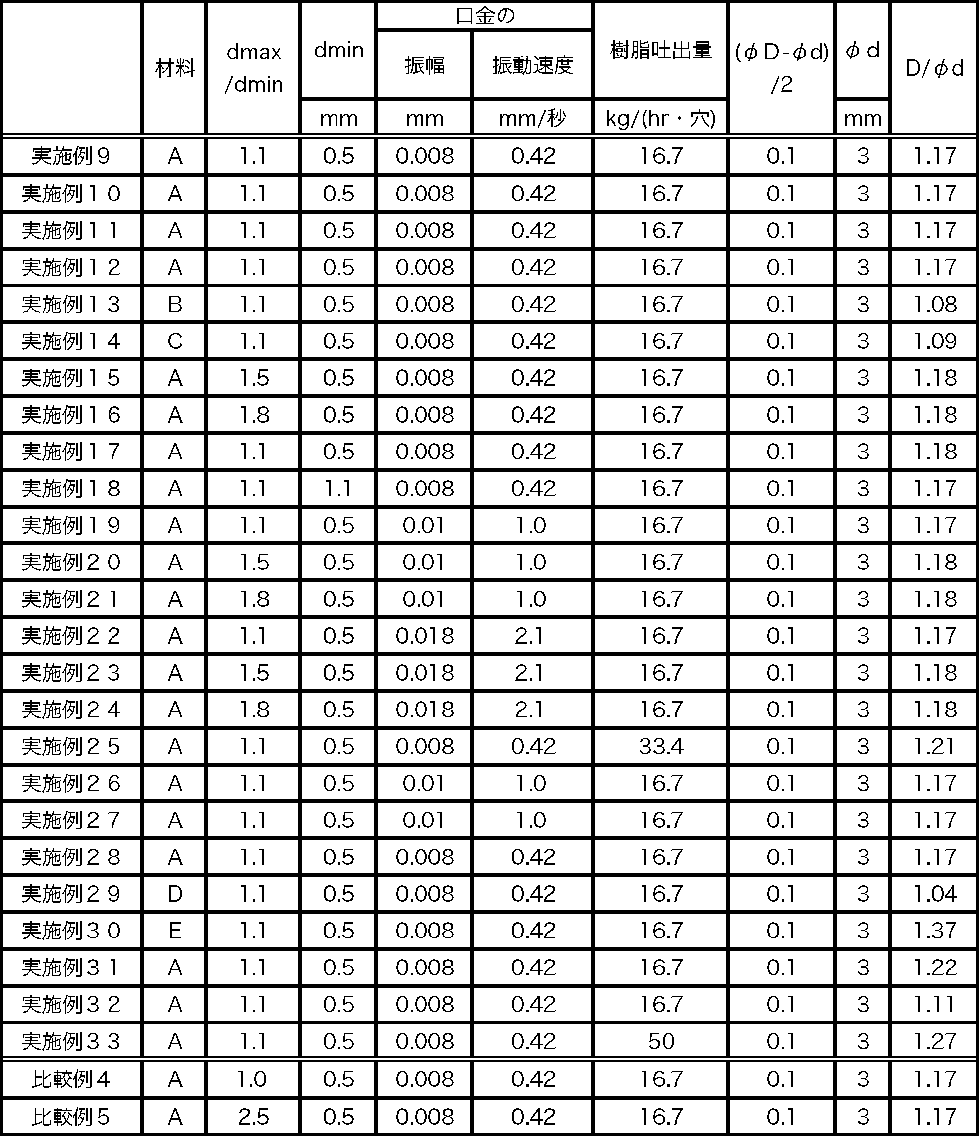

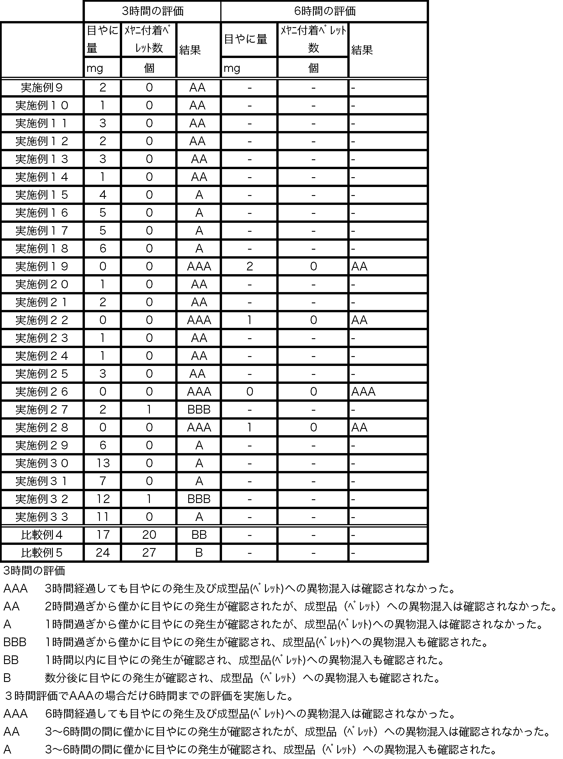
Claims (19)
- 押出機から供給される、熱可塑性樹脂組成物からなる溶融樹脂をストランド状に押し出すための樹脂押出用ダイであって、
前記溶融樹脂が押し出される吐出ノズルを有する口金と、
前記吐出ノズルの先端部の周囲に間隙を形成する気体流出口を有し、前記口金と前記気体流出口の間に空間を形成するように前記口金の少なくとも一部を覆うカバーと、
前記空間に気体を供給するための気体供給口とを有し、
前記気体流出口が、前記吐出ノズルの先端部の周囲に、最大幅dmax/最小幅dminが1.05以上2.0以下の間隙を形成することにより、前記間隙から流出する気体を乱流化することを特徴とする樹脂押出用ダイ。 - 前記吐出ノズルの吐出孔および前記気体流出口がいずれも円形であり、前記気体流出口の中心が、前記吐出孔の中心から偏奇した位置に配置されることを特徴とする請求項1記載の樹脂押出用ダイ。
- 前記カバーと前記口金との相対的な位置関係を調整するための調整機構をさらに有することを特徴とする請求項1記載の樹脂押出用ダイ。
- 前記口金を、
振幅:0.005mm~0.2mm
振動速度:0.3mm/秒~5mm/秒
の範囲内で振動させる振動手段をさらに有することを特徴とする請求項1記載の樹脂押出用ダイ。 - 前記吐出ノズルとして、内径φdが2≦φd≦7mmの吐出ノズルを用いることを特徴とする請求項1記載の樹脂押出用ダイ。
- 前記間隙が0.1~1mmであることを特徴とする請求項1記載の樹脂押出用ダイ。
- 前記吐出ノズルを複数有するとともに、前記押出機から供給される前記溶融樹脂の圧力を均一化させて前記複数の吐出ノズルに供給するためのマニホールド120を備え、
前記複数の吐出ノズルの、前記溶融樹脂の押し出し方向と直交する最小の断面積の合計面積(S1)と、前記マニホールド120の前記押し出し方向と直交する最大断面積(S2)との比S1/S2で定められるノズル開口率が、10%≧S1/S2≧1.2%であることを特徴とする請求項1記載の樹脂押出用ダイ。 - 前記吐出ノズルの長さLが50mm≧L≧15mmであることを特徴とする請求項1記載の樹脂押出用ダイ。
- 熱可塑性樹脂組成物からなる溶融樹脂をストランド状に押し出すための樹脂押出用ダイを有する押出機を用いた熱可塑性樹脂組成物の押出成型方法であって、
前記樹脂押出用ダイが、
前記溶融樹脂が押し出される吐出ノズルを有する口金と、
前記吐出ノズルの先端部の周囲に最大幅dmax/最小幅dminが1.05以上2.0以下の間隙を形成する気体流出口を有し、前記口金と前記気体流出口の間に空間を形成するように前記口金の少なくとも一部を覆うカバーと、
前記空間に気体を供給するための気体供給口とを有する樹脂押出用ダイであり、
前記ダイの前記気体供給口から気体を供給しながら押出成形を行うことにより、前記間隙から流出する気体を乱流化させて前記吐出ノズルの先端部近傍へ吹き付け、前記ダイから押し出される溶融樹脂の一部が前記吐出ノズルの先端部に堆積することを抑制することを特徴とする熱可塑性樹脂組成物の押出成型方法。 - 前記吐出ノズルの先端部の肉厚Ltが0<Lt≦2mmであり、
前記吐出ノズルの先端部近傍へ気体を吹き付けながら、吐出ノズルあたり14kg/時以上、40kg/時以下の吐出量で前記溶融樹脂を押し出すことにより、前記吐出ノズルの先端部近傍で、溶融樹脂をバラス効果によって膨張させ、当該膨張部分で前記気体の流れを変化させることにより、前記押し出された溶融樹脂の一部が前記吐出ノズルの先端部に堆積することをさらに抑制することを特徴とする請求項9記載の熱可塑性樹脂組成物の押出成型方法。 - 前記溶融樹脂の前記バラス効果による膨張率が、前記吐出ノズルの内径をφd、前記溶融樹脂が前記吐出ノズルからストランド状に押し出されて膨張した後の樹脂ストランドの直径をDとした場合に、1.35≧D/φd≧1.05となるように前記吐出量を決定することを特徴とする請求項10に記載の熱可塑性樹脂組成物の押出成型方法。
- 剪断粘度が、温度280℃、剪断速度100/秒において50Pa・秒以上、5000Pa・秒以下である熱可塑性樹脂組成物を用いることを特徴とする請求項9に記載の熱可塑性樹脂組成物の押出成型方法。
- 前記吐出ノズルの先端部近傍における前記気体の線速度が4~100m/秒であることを特徴とする請求項9に記載の熱可塑性樹脂組成物の押出成型方法。
- 前記吐出ノズルとして、内径φdが2≦φd≦7mmの吐出ノズルを用いることを特徴とする請求項9記載の熱可塑性樹脂組成物の押出成型方法。
- 前記間隙が0.1~1mmであることを特徴とする請求項9に記載の熱可塑性樹脂組成物の押出成型方法。
- 前記樹脂押出用ダイは、前記吐出ノズルを複数有するとともに、前記押出機から供給される前記溶融樹脂の圧力を均一化させて前記複数の吐出ノズルに供給するためのマニホールド120を備え、
前記複数の吐出ノズルの、前記溶融樹脂の押し出し方向と直交する最小の断面積の合計面積(S1)と、前記マニホールド120の前記押し出し方向と直交する最大断面積(S2)との比S1/S2で定められるノズル開口率が、10%≧S1/S2≧1.2%であることを特徴とする請求項9に記載の熱可塑性樹脂組成物の押出成型方法。 - 前記吐出ノズルの長さLが50mm≧L≧15mmであることを特徴とする請求項9に記載の熱可塑性樹脂組成物の押出成型方法。
- 前記押し出された樹脂ストランドを、搬送経路に設けられたガイドローラーに接するように、かつ引き取り速度Vs(cm/秒)で引き取るとともに、
前記ガイドローラーの前記樹脂ストランドの接する外周面の移動速度をVr(cm/秒)とした場合に、0.7≧Vr/Vs≧-0.2の関係を満たすように、前記引き取り速度及び前記移動速度並びに前記ガイドローラーの回転方向を決定することを特徴とする請求項9に記載の熱可塑性樹脂組成物の押出成型方法。 - 前記樹脂押出用ダイを
振幅:0.005mm~0.2mm
振動速度:0.3mm/秒~5mm/秒
の範囲内で振動させながら、前記溶融樹脂の押し出しを行うことを特徴とする請求項9に記載の熱可塑性樹脂組成物の押出成型方法。
Priority Applications (3)
| Application Number | Priority Date | Filing Date | Title |
|---|---|---|---|
| CN201080024319.8A CN102458787B (zh) | 2009-06-04 | 2010-05-19 | 树脂挤出模具以及使用该树脂挤出模具的挤出成型方法 |
| JP2011518236A JP5584208B2 (ja) | 2009-06-04 | 2010-05-19 | 樹脂押出用ダイ及びそれを用いた押出成形方法 |
| US13/302,099 US8936454B2 (en) | 2009-06-04 | 2011-11-22 | Resin extrusion die and extrusion method using the same |
Applications Claiming Priority (2)
| Application Number | Priority Date | Filing Date | Title |
|---|---|---|---|
| JP2009-135328 | 2009-06-04 | ||
| JP2009135328 | 2009-06-04 |
Related Child Applications (1)
| Application Number | Title | Priority Date | Filing Date |
|---|---|---|---|
| US13/302,099 Continuation US8936454B2 (en) | 2009-06-04 | 2011-11-22 | Resin extrusion die and extrusion method using the same |
Publications (1)
| Publication Number | Publication Date |
|---|---|
| WO2010140310A1 true WO2010140310A1 (ja) | 2010-12-09 |
Family
ID=43297453
Family Applications (1)
| Application Number | Title | Priority Date | Filing Date |
|---|---|---|---|
| PCT/JP2010/003356 Ceased WO2010140310A1 (ja) | 2009-06-04 | 2010-05-19 | 樹脂押出用ダイ及びそれを用いた押出成型方法 |
Country Status (5)
| Country | Link |
|---|---|
| US (1) | US8936454B2 (ja) |
| JP (1) | JP5584208B2 (ja) |
| CN (1) | CN102458787B (ja) |
| MY (1) | MY154199A (ja) |
| WO (1) | WO2010140310A1 (ja) |
Cited By (8)
| Publication number | Priority date | Publication date | Assignee | Title |
|---|---|---|---|---|
| CN102211392A (zh) * | 2011-06-02 | 2011-10-12 | 江苏海达电缆有限公司 | 一种具有曲线型机颈流道的挤塑机 |
| WO2012131980A1 (ja) * | 2011-03-31 | 2012-10-04 | ポリプラスチックス株式会社 | 熱可塑性樹脂組成物ペレットの製造方法、押出機及びダイプレート |
| JP2012232432A (ja) * | 2011-04-28 | 2012-11-29 | Mitsubishi Engineering Plastics Corp | 樹脂押出用ダイ |
| WO2013004390A1 (de) * | 2011-07-06 | 2013-01-10 | Automatik Plastics Machinery Gmbh | Verfahren und vorrichtung zum herstellen von granulatkörnern |
| JP2017047638A (ja) * | 2015-09-03 | 2017-03-09 | 三菱エンジニアリングプラスチックス株式会社 | 樹脂押出用ダイ及び樹脂ペレット製造装置 |
| JP2021066035A (ja) * | 2019-10-18 | 2021-04-30 | 株式会社日本製鋼所 | ストランド製造装置及びペレット製造装置 |
| WO2022185623A1 (ja) * | 2021-03-03 | 2022-09-09 | 株式会社日本製鋼所 | 押出装置およびそれに用いられる押出成形用ダイ、監視装置およびプログラム、ストランドの製造方法、ならびに、ストランド径の調整方法 |
| JP7470882B1 (ja) | 2024-01-26 | 2024-04-18 | 東京インキ株式会社 | ダイスセットおよび押出機 |
Families Citing this family (11)
| Publication number | Priority date | Publication date | Assignee | Title |
|---|---|---|---|---|
| WO2015039130A1 (en) * | 2013-09-16 | 2015-03-19 | Madesolid, Inc. | Rheological modification of extrusions for use in additive manufacturing |
| EP3254824B1 (en) * | 2015-02-04 | 2021-10-06 | Toray Industries, Inc. | Sheet production device and sheet production method |
| US10694777B2 (en) * | 2015-03-31 | 2020-06-30 | Kt & G Corporation | Method and apparatus for manufacturing flavor capsule of tobacco |
| WO2017203943A1 (ja) * | 2016-05-24 | 2017-11-30 | 住友ベークライト株式会社 | 繊維含有粒状樹脂構造物、繊維含有粒状樹脂構造物の製造方法、繊維強化樹脂硬化物、及び繊維強化樹脂成形品 |
| EP3613796B1 (en) * | 2017-05-26 | 2021-02-10 | Mitsubishi Gas Chemical Company, Inc. | Method for producing resin pellets |
| US11207799B2 (en) * | 2017-06-26 | 2021-12-28 | Wisconsin Alumni Research Foundation | Pelletization gas guide |
| US11065817B2 (en) * | 2018-08-14 | 2021-07-20 | Massivit 3D Printing Technologies Ltd. | Extrusion orifice cleaning |
| CN113021835A (zh) * | 2021-03-04 | 2021-06-25 | 浙江凯阳新材料股份有限公司 | 一种消除模唇积渣方法 |
| CN115418735A (zh) * | 2022-09-02 | 2022-12-02 | 安徽质恒新材料有限公司 | 一种复合纤维拉伸设备 |
| CN117103501B (zh) * | 2023-08-31 | 2026-03-10 | 浙江美源新材料股份有限公司 | 一种塑料粒子生产设备及其方法 |
| EP4674592A1 (de) * | 2024-07-04 | 2026-01-07 | Feddem GmbH & Co. KG | Verfahren und vorrichtung zur herstellung von polymersträngen mittels eines formwerkzeugs |
Citations (8)
| Publication number | Priority date | Publication date | Assignee | Title |
|---|---|---|---|---|
| JPS5789212U (ja) * | 1980-11-20 | 1982-06-02 | ||
| JPH04135823A (ja) * | 1990-09-28 | 1992-05-11 | Hitachi Cable Ltd | 熱可塑性材料の押出し成形方法 |
| JPH09225994A (ja) * | 1996-02-20 | 1997-09-02 | Sumitomo Electric Ind Ltd | 樹脂組成物の押出方法 |
| JPH09295334A (ja) * | 1996-05-01 | 1997-11-18 | Mitsubishi Eng Plast Kk | 目ヤニ防止性異型押出成形用ダイ |
| JPH10264227A (ja) * | 1997-03-26 | 1998-10-06 | Mitsui Chem Inc | 押出成形方法及びダイ |
| JPH11179781A (ja) * | 1997-12-24 | 1999-07-06 | Sumitomo Bakelite Co Ltd | 樹脂押出成形装置 |
| JP2003305761A (ja) * | 2002-04-11 | 2003-10-28 | Japan Steel Works Ltd:The | 樹脂組成物の押出方法及び装置 |
| JP2007320056A (ja) * | 2006-05-30 | 2007-12-13 | Mitsubishi Engineering Plastics Corp | 押出成形用ダイ |
Family Cites Families (5)
| Publication number | Priority date | Publication date | Assignee | Title |
|---|---|---|---|---|
| US2765153A (en) * | 1951-11-14 | 1956-10-02 | Gielow Christian | Process and means for handling plastic masses |
| JPS5789212A (en) | 1980-11-25 | 1982-06-03 | Tdk Electronics Co Ltd | Composite ceramic electronic material |
| US6010592A (en) * | 1994-06-23 | 2000-01-04 | Kimberly-Clark Corporation | Method and apparatus for increasing the flow rate of a liquid through an orifice |
| US7018188B2 (en) * | 2003-04-08 | 2006-03-28 | The Procter & Gamble Company | Apparatus for forming fibers |
| EP1645381A4 (en) * | 2003-07-16 | 2008-04-16 | Idemitsu Kosan Co | DEVICE FOR EXPLOITING RESIN MATERIAL WITH ULTRASOUND VIBRATIONS, METHOD FOR MELTING MOLDING RESIN MATERIAL USING THE DEVICE AND RESIN COMPOSITION |
-
2010
- 2010-05-19 WO PCT/JP2010/003356 patent/WO2010140310A1/ja not_active Ceased
- 2010-05-19 MY MYPI2011005875A patent/MY154199A/en unknown
- 2010-05-19 CN CN201080024319.8A patent/CN102458787B/zh active Active
- 2010-05-19 JP JP2011518236A patent/JP5584208B2/ja active Active
-
2011
- 2011-11-22 US US13/302,099 patent/US8936454B2/en active Active
Patent Citations (8)
| Publication number | Priority date | Publication date | Assignee | Title |
|---|---|---|---|---|
| JPS5789212U (ja) * | 1980-11-20 | 1982-06-02 | ||
| JPH04135823A (ja) * | 1990-09-28 | 1992-05-11 | Hitachi Cable Ltd | 熱可塑性材料の押出し成形方法 |
| JPH09225994A (ja) * | 1996-02-20 | 1997-09-02 | Sumitomo Electric Ind Ltd | 樹脂組成物の押出方法 |
| JPH09295334A (ja) * | 1996-05-01 | 1997-11-18 | Mitsubishi Eng Plast Kk | 目ヤニ防止性異型押出成形用ダイ |
| JPH10264227A (ja) * | 1997-03-26 | 1998-10-06 | Mitsui Chem Inc | 押出成形方法及びダイ |
| JPH11179781A (ja) * | 1997-12-24 | 1999-07-06 | Sumitomo Bakelite Co Ltd | 樹脂押出成形装置 |
| JP2003305761A (ja) * | 2002-04-11 | 2003-10-28 | Japan Steel Works Ltd:The | 樹脂組成物の押出方法及び装置 |
| JP2007320056A (ja) * | 2006-05-30 | 2007-12-13 | Mitsubishi Engineering Plastics Corp | 押出成形用ダイ |
Cited By (18)
| Publication number | Priority date | Publication date | Assignee | Title |
|---|---|---|---|---|
| JP5728077B2 (ja) * | 2011-03-31 | 2015-06-03 | ポリプラスチックス株式会社 | 熱可塑性樹脂組成物ペレットの製造方法、押出機及びダイプレート |
| WO2012131980A1 (ja) * | 2011-03-31 | 2012-10-04 | ポリプラスチックス株式会社 | 熱可塑性樹脂組成物ペレットの製造方法、押出機及びダイプレート |
| TWI564136B (zh) * | 2011-03-31 | 2017-01-01 | Polyplastics Co | Thermoplastic resin composition, a method for producing a compressed product, an extruder, and a mold plate |
| CN103354776B (zh) * | 2011-03-31 | 2016-03-30 | 宝理塑料株式会社 | 热塑性树脂组合物颗粒的制造方法、挤出机及模具 |
| CN103354776A (zh) * | 2011-03-31 | 2013-10-16 | 宝理塑料株式会社 | 热塑性树脂组合物颗粒的制造方法、挤出机及模具 |
| JP2012232432A (ja) * | 2011-04-28 | 2012-11-29 | Mitsubishi Engineering Plastics Corp | 樹脂押出用ダイ |
| CN102211392B (zh) * | 2011-06-02 | 2013-03-20 | 江苏海达电缆有限公司 | 一种具有曲线型机颈流道的挤塑机 |
| CN102211392A (zh) * | 2011-06-02 | 2011-10-12 | 江苏海达电缆有限公司 | 一种具有曲线型机颈流道的挤塑机 |
| WO2013004390A1 (de) * | 2011-07-06 | 2013-01-10 | Automatik Plastics Machinery Gmbh | Verfahren und vorrichtung zum herstellen von granulatkörnern |
| US9808979B2 (en) | 2011-07-06 | 2017-11-07 | Maag Automatik Gmbh | Method and device for making granules |
| JP2017047638A (ja) * | 2015-09-03 | 2017-03-09 | 三菱エンジニアリングプラスチックス株式会社 | 樹脂押出用ダイ及び樹脂ペレット製造装置 |
| JP2021066035A (ja) * | 2019-10-18 | 2021-04-30 | 株式会社日本製鋼所 | ストランド製造装置及びペレット製造装置 |
| JP7349316B2 (ja) | 2019-10-18 | 2023-09-22 | 株式会社日本製鋼所 | ストランド製造装置及びペレット製造装置 |
| US12030223B2 (en) | 2019-10-18 | 2024-07-09 | The Japan Steel Works, Ltd. | Strand manufacturing apparatus and pellet manufacturing apparatus |
| US12496746B2 (en) | 2019-10-18 | 2025-12-16 | The Japan Steel Works, Ltd. | Strand manufacturing apparatus and pellet manufacturing apparatus |
| WO2022185623A1 (ja) * | 2021-03-03 | 2022-09-09 | 株式会社日本製鋼所 | 押出装置およびそれに用いられる押出成形用ダイ、監視装置およびプログラム、ストランドの製造方法、ならびに、ストランド径の調整方法 |
| JP7538744B2 (ja) | 2021-03-03 | 2024-08-22 | 株式会社日本製鋼所 | 押出装置およびそれに用いられる押出成形用ダイ、監視装置およびプログラム、ストランドの製造方法、ならびに、ストランド径の調整方法 |
| JP7470882B1 (ja) | 2024-01-26 | 2024-04-18 | 東京インキ株式会社 | ダイスセットおよび押出機 |
Also Published As
| Publication number | Publication date |
|---|---|
| US20120126466A1 (en) | 2012-05-24 |
| CN102458787A (zh) | 2012-05-16 |
| CN102458787B (zh) | 2014-09-03 |
| JP5584208B2 (ja) | 2014-09-03 |
| US8936454B2 (en) | 2015-01-20 |
| MY154199A (en) | 2015-05-15 |
| JPWO2010140310A1 (ja) | 2012-11-15 |
Similar Documents
| Publication | Publication Date | Title |
|---|---|---|
| JP5584208B2 (ja) | 樹脂押出用ダイ及びそれを用いた押出成形方法 | |
| JP5638882B2 (ja) | 熱可塑性樹脂組成物の押出成形方法 | |
| CN102202852B (zh) | 用于聚合物的挤出喷嘴 | |
| JP7316366B2 (ja) | 液晶ポリマーフィルム及び高速通信用基板 | |
| JP5654296B2 (ja) | 熱可塑性樹脂組成物の押出成形方法 | |
| KR20190015719A (ko) | 펠렛 제조 장치 및 펠렛 제조 방법 | |
| KR101444625B1 (ko) | 압출 다이 헤드 | |
| US20230331983A1 (en) | Liquid crystal polymer film and substrate for high-speed communication | |
| US9808979B2 (en) | Method and device for making granules | |
| JP5774901B2 (ja) | 樹脂押出用ダイ | |
| TW565498B (en) | Die apparatus for use in resin extrusion machine, and extrusion molding method | |
| JP2003220607A (ja) | メヤニ発生防止装置 | |
| JP6671495B2 (ja) | 熱可塑性樹脂フィルムの製造方法 | |
| JP6517637B2 (ja) | 樹脂押出用ダイ及び樹脂ペレット製造装置 | |
| JP5728077B2 (ja) | 熱可塑性樹脂組成物ペレットの製造方法、押出機及びダイプレート | |
| JP7426450B1 (ja) | ガラス繊維強化ポリアミド樹脂組成物の製造方法 | |
| WO2023203914A1 (ja) | ガラス繊維強化ポリエステル系樹脂組成物の製造方法 | |
| JP2004268421A (ja) | ストランドカッターおよびそれを用いたペレットの製造方法 | |
| WO2023203913A1 (ja) | ガラス繊維強化ポリエステル系樹脂組成物の製造方法 | |
| JP6317223B2 (ja) | 樹脂ペレット製造方法及び樹脂ペレット製造装置 | |
| US12522703B2 (en) | Polymer film and substrate for communication | |
| JP2002120222A (ja) | ペレット化用樹脂カッティング装置及びペレット化方法 | |
| JP2014034199A (ja) | メヤニの発生を抑制する装置及びストランドの製造方法 | |
| JP2024047706A (ja) | ガラス繊維強化ポリアミド樹脂組成物の製造方法 | |
| JP2016055568A (ja) | ダイプレート及びそれを用いた熱可塑性樹脂組成物ストランドの製造方法 |
Legal Events
| Date | Code | Title | Description |
|---|---|---|---|
| WWE | Wipo information: entry into national phase |
Ref document number: 201080024319.8 Country of ref document: CN |
|
| 121 | Ep: the epo has been informed by wipo that ep was designated in this application |
Ref document number: 10783098 Country of ref document: EP Kind code of ref document: A1 |
|
| WWE | Wipo information: entry into national phase |
Ref document number: 2011518236 Country of ref document: JP |
|
| NENP | Non-entry into the national phase |
Ref country code: DE |
|
| 122 | Ep: pct application non-entry in european phase |
Ref document number: 10783098 Country of ref document: EP Kind code of ref document: A1 |