WO2010137340A1 - 応力処理装置および施工システム - Google Patents
応力処理装置および施工システム Download PDFInfo
- Publication number
- WO2010137340A1 WO2010137340A1 PCT/JP2010/003599 JP2010003599W WO2010137340A1 WO 2010137340 A1 WO2010137340 A1 WO 2010137340A1 JP 2010003599 W JP2010003599 W JP 2010003599W WO 2010137340 A1 WO2010137340 A1 WO 2010137340A1
- Authority
- WO
- WIPO (PCT)
- Prior art keywords
- pin hole
- head
- construction
- disk
- unit
- Prior art date
- Legal status (The legal status is an assumption and is not a legal conclusion. Google has not performed a legal analysis and makes no representation as to the accuracy of the status listed.)
- Ceased
Links
Images






















Classifications
-
- F—MECHANICAL ENGINEERING; LIGHTING; HEATING; WEAPONS; BLASTING
- F01—MACHINES OR ENGINES IN GENERAL; ENGINE PLANTS IN GENERAL; STEAM ENGINES
- F01D—NON-POSITIVE DISPLACEMENT MACHINES OR ENGINES, e.g. STEAM TURBINES
- F01D5/00—Blades; Blade-carrying members; Heating, heat-insulating, cooling or antivibration means on the blades or the members
- F01D5/005—Repairing methods or devices
-
- B—PERFORMING OPERATIONS; TRANSPORTING
- B23—MACHINE TOOLS; METAL-WORKING NOT OTHERWISE PROVIDED FOR
- B23K—SOLDERING OR UNSOLDERING; WELDING; CLADDING OR PLATING BY SOLDERING OR WELDING; CUTTING BY APPLYING HEAT LOCALLY, e.g. FLAME CUTTING; WORKING BY LASER BEAM
- B23K26/00—Working by laser beam, e.g. welding, cutting or boring
- B23K26/352—Working by laser beam, e.g. welding, cutting or boring for surface treatment
-
- B—PERFORMING OPERATIONS; TRANSPORTING
- B23—MACHINE TOOLS; METAL-WORKING NOT OTHERWISE PROVIDED FOR
- B23K—SOLDERING OR UNSOLDERING; WELDING; CLADDING OR PLATING BY SOLDERING OR WELDING; CUTTING BY APPLYING HEAT LOCALLY, e.g. FLAME CUTTING; WORKING BY LASER BEAM
- B23K26/00—Working by laser beam, e.g. welding, cutting or boring
- B23K26/352—Working by laser beam, e.g. welding, cutting or boring for surface treatment
- B23K26/356—Working by laser beam, e.g. welding, cutting or boring for surface treatment by shock processing
-
- F—MECHANICAL ENGINEERING; LIGHTING; HEATING; WEAPONS; BLASTING
- F01—MACHINES OR ENGINES IN GENERAL; ENGINE PLANTS IN GENERAL; STEAM ENGINES
- F01D—NON-POSITIVE DISPLACEMENT MACHINES OR ENGINES, e.g. STEAM TURBINES
- F01D5/00—Blades; Blade-carrying members; Heating, heat-insulating, cooling or antivibration means on the blades or the members
- F01D5/12—Blades
- F01D5/28—Selecting particular materials; Particular measures relating thereto; Measures against erosion or corrosion
- F01D5/286—Particular treatment of blades, e.g. to increase durability or resistance against corrosion or erosion
-
- B—PERFORMING OPERATIONS; TRANSPORTING
- B23—MACHINE TOOLS; METAL-WORKING NOT OTHERWISE PROVIDED FOR
- B23K—SOLDERING OR UNSOLDERING; WELDING; CLADDING OR PLATING BY SOLDERING OR WELDING; CUTTING BY APPLYING HEAT LOCALLY, e.g. FLAME CUTTING; WORKING BY LASER BEAM
- B23K2101/00—Articles made by soldering, welding or cutting
- B23K2101/001—Turbines
-
- F—MECHANICAL ENGINEERING; LIGHTING; HEATING; WEAPONS; BLASTING
- F05—INDEXING SCHEMES RELATING TO ENGINES OR PUMPS IN VARIOUS SUBCLASSES OF CLASSES F01-F04
- F05D—INDEXING SCHEME FOR ASPECTS RELATING TO NON-POSITIVE-DISPLACEMENT MACHINES OR ENGINES, GAS-TURBINES OR JET-PROPULSION PLANTS
- F05D2230/00—Manufacture
- F05D2230/10—Manufacture by removing material
- F05D2230/13—Manufacture by removing material using lasers
-
- Y—GENERAL TAGGING OF NEW TECHNOLOGICAL DEVELOPMENTS; GENERAL TAGGING OF CROSS-SECTIONAL TECHNOLOGIES SPANNING OVER SEVERAL SECTIONS OF THE IPC; TECHNICAL SUBJECTS COVERED BY FORMER USPC CROSS-REFERENCE ART COLLECTIONS [XRACs] AND DIGESTS
- Y10—TECHNICAL SUBJECTS COVERED BY FORMER USPC
- Y10T—TECHNICAL SUBJECTS COVERED BY FORMER US CLASSIFICATION
- Y10T29/00—Metal working
- Y10T29/49—Method of mechanical manufacture
- Y10T29/49316—Impeller making
- Y10T29/4932—Turbomachine making
- Y10T29/49321—Assembling individual fluid flow interacting members, e.g., blades, vanes, buckets, on rotary support member
Definitions
- Embodiments of the present invention relate to a stress processing apparatus and a construction system for a steam turbine in which a stress improving process is performed on one or both of a structure, for example, a turbine blade and a disk.
- the steam turbine includes a plurality of turbine rotor blades that are implanted in the circumferential direction of the rotor, and stationary blades (nozzles) that are fixed to the turbine casing.
- a combination of a pair of turbine blades and stationary blades forms a turbine stage.
- a steam turbine is formed by arranging a plurality of turbine stages on a disk.
- the turbine rotor blade and the disk are made of a material having a high tensile strength of, for example, 500 kg / mm 2 or more (for example, high-altitude copper) so as to be able to withstand the centrifugal force during operation. Is done.
- This high tensile strength material is highly sensitive to stress corrosion cracking (hereinafter "SCC").
- turbine blades having a long blade length tend to be employed in the low-pressure final stage for the purpose of reducing exhaust loss.
- the centrifugal force acting on the blade increases. Therefore, the joint between the blade and the disk where the stress is concentrated needs to have sufficient strength against the low cycle fatigue accompanying the start and stop and the high cycle fatigue under the high average stress and the corrosive environment.
- the present invention has been made to solve such problems, and a stress processing apparatus and construction system capable of reducing the occurrence of stress corrosion cracking on the inner surface of a hole formed in a structure and improving the fatigue strength.
- the purpose is to provide.
- a stress processing apparatus performs peening for irradiating a laser beam in a hole formed in a structure, and forms a compressive stress region in the hole, and the laser.
- a laser part having an optical fiber for guiding light to the head part; an injection part for injecting liquid into the hole; and supporting the optical fiber so that the injected liquid can flow, and being fixed in the head part.
- a construction part provided with a supporting part.
- a turbine rotor blade having a blade fork, a rotor disk having a disk fork with which the blade fork engages, a processing unit that simultaneously performs a reaming process, and the rotor is rotated.
- a laser having a rotor rotating portion for positioning the disk at a predetermined position, a head portion for performing peening, and an optical fiber for guiding an irradiated laser to the head portion, and performing peening by irradiating the inside of the pin hole with laser.
- a support part that supports the optical fiber so as to be able to pass the jetted liquid and is fixed in the head part.
- An image of a stress processing device comprising a construction section for forming a contraction stress area, a drying section for drying the liquid sprayed into the pin hole, and an image of the compression stress area formed in the pin hole.
- a recognition unit for recognizing the compressive stress region based on the image, and an assembly unit for assembling the turbine rotor blade and the disk, and each of the parts at different positions on the same circumference of the rotor. Arrange each part or each part at a different position on the same circumference of the rotor, and arrange each part having the same function at the opposing position of the disk on the turbine side and the disk on the collector side.
- the occurrence of stress corrosion cracking on the inner surface of the hole formed in the structure can be reduced, and the fatigue strength can be improved.
- FIG. 1 It is a perspective view which shows the structure of the stress processing apparatus which concerns on Embodiment 3.
- FIG. It is a perspective view which shows the structure of the stress processing apparatus which concerns on Embodiment 4.
- FIG. It is an expanded sectional view of the entrance part of a pin hole. It is an expanded sectional view of the exit part of a pin hole. It is an expanded sectional view of the entrance part of a pin hole. It is an expanded sectional view of the exit part of a pin hole. It is an enlarged side view of the principal part of the head part and boom of the stress processing apparatus which concerns on Embodiment 7.
- FIG. It is an enlarged front view of the principal part of the head part and boom of the stress processing apparatus which concerns on Embodiment 7.
- FIG. 8 It is an enlarged side view of the principal part of the head part and boom of the stress processing apparatus which concerns on Embodiment 8.
- FIG. It is an enlarged front view of the principal part of the head part and boom of the stress processing apparatus which concerns on Embodiment 8.
- FIG. It is an enlarged side view of the principal part of the head part and boom of the stress processing apparatus which concerns on the modification 2 of Embodiment 8.
- FIG. It is an enlarged front view of the principal part of the head part of a stress processing apparatus which concerns on the modification 2 of Embodiment 8, and a boom. It is a figure which shows the construction track
- FIG. 25A and FIG. 25B It is principal part sectional drawing which shows the side surface of the construction head of the stress processing apparatus which concerns on the modification 1 of Embodiment 11. It is a front view for demonstrating the rotation state of the construction head shown to FIG. 25A and FIG. 25B. It is sectional drawing for demonstrating operation
- FIG. It is sectional drawing which shows the EE cross section of FIG. It is a front view of a turbine rotor blade and a disk for explaining a drying apparatus according to a twelfth embodiment. It is the arrow line view seen from the X direction of the drying head for demonstrating the drying apparatus which concerns on Embodiment 12.
- FIG. 16 is a cross-sectional view illustrating a combined head according to a fourteenth embodiment. It is a figure which shows the collection
- FIG. 22 is a cross-sectional view of a main part of a head distal end portion of a stress processing apparatus according to Embodiment 20.
- FIG. 39 is a cross-sectional view showing the XX cross section of FIG. 38. It is a perspective view which shows the support part shown in FIG.
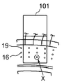
- FIG. 1A to 1C are views for explaining that the turbine rotor blade 10 and the disk 12 are reamed simultaneously.
- 1A is a front view showing a coupling structure of the turbine rotor blade 10 and the disk 12
- FIG. 1B is a side view
- FIG. 1C is an enlarged view of a portion X in FIG. 1B.
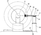
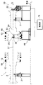
- FIG. 2 is a diagram for explaining the configuration of the stress processing device 24 according to the first embodiment, and is a front view showing a case where stress is improved to the pin hole 15 of the combined structure of the turbine rotor blade 10 and the disk 12.
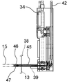
- FIG. 3 is an arrow view showing the configuration of FIG. 2 viewed from the A direction.
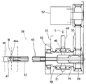
- FIG. 4 is an enlarged view showing the head portion shown in FIG.
- symbol is attached about the same component.
- the turbine rotor blade 10 has a blade fork 11 at the lower end.
- the disk 12 of the rotor 1 has a disk fork 13 at the upper end.
- the blade fork 11 and the disk fork 13 are formed to be able to engage with each other.
- a pilot hole 16 having a diameter smaller than the hole diameter of the pin hole 15 by about 0.5 to 1.0 mm is formed in advance.
- the reamer processing apparatus 100 includes a rotation drive unit 101, a plurality of reamer tools 102, and a moving unit (not shown).
- the rotation drive unit 101 rotates a plurality of reamer tools 102 simultaneously and at the same speed.
- the rotation drive unit 101 and the reamer tool 102 are moved in the axial direction of the pin hole 15 (in the direction of arrow 14 in the figure) by the moving unit.
- the reamer processing apparatus 100 functions as a “processing section that performs reamer processing simultaneously on a turbine rotor blade having a blade fork and a rotor disk having a disk fork with which the blade fork is engaged”.
- the temporary pin 19 is inserted into the lower hole 16 to position the lower hole 16 coaxially.
- a plurality of reamer tools 102 are simultaneously rotated at the same speed by the rotation drive unit 101, moved in the axial direction of the pin hole 15, the lower hole 16 is cut, and the pin hole 15 is aligned and processed. To do.
- the positional displacement between the turbine rotor blade 10 and the pin holes 15 of the disk 12 is eliminated, and the load on the pin holes 15 and the pins during operation is reduced.
- the generated chips in the pin hole 15 are removed.
- the configuration of the stress processing device 24 of this embodiment will be described.
- the stress processing apparatus 24 according to the present embodiment peens the pin holes 15 of the blade fork 11 and the disk fork 13 for the purpose of improving fatigue strength and removing residual stress.
- the stress processing device 24 includes a rotor rotating unit 20, a construction unit 29, and a control unit 18 that drives and controls these parts.
- the rotor rotating unit 20 includes a bed 21 and a rotor rotating device 22.
- One of the counters 21 is disposed at both ends of the rotor 1, and both ends of the rotor 1 are rotatably supported.
- the rotor rotating device 22 is disposed in the vicinity of the tip of the rotor 1.
- the rotor rotating device 22 includes, for example, a stepping motor, rotates the disk 12 to a predetermined position around the central axis 27 of the shaft 2 of the rotor 1, and enables construction by the construction section 29 at the predetermined position. .
- the rotor rotating device 22 includes “a turbine rotor blade having a blade fork, and a disk having a disk fork which is assembled by being engaged with the blade fork and in which a pin hole penetrating the blade fork is formed. It functions as a “rotor rotating section that rotates the rotor and positions the disk at a predetermined position”.
- the construction unit 29 is disposed near the front of the rotor 1 and includes a pedestal 30, a rotor radial direction drive unit 31, a rotor tangential direction drive unit 32, a head feed drive unit 33, a head rotation drive unit 34, a boom 35, and a head unit 36. Prepare.
- the pedestal 30 is configured to be movable in parallel with the radial direction 17 and the central axis 27 of the rotor 1.
- the radial direction 17 of the rotor 1 indicates a direction parallel to the horizontal direction.
- the rotor radial direction drive unit 31 has a rotor radial direction drive shaft disposed above the pedestal 30 and moves the boom 35 in the radial direction 17 of the rotor 1.
- the rotor tangential direction drive unit 32 has a rotor tangential direction drive shaft disposed in the boom 35, and moves the head unit 36 in the tangential direction of the rotor 1.
- the head feed driving unit 33 moves the construction head 38 of the head unit 36 in parallel with the central axis 27 of the rotor 1.
- the head rotation drive unit 34 has a rotary motor disposed in the head unit 36 and rotates the construction head 38 of the head unit 36 so that a compression stress region described later is formed on the inner surface of the pin hole 15.
- the boom 35 is formed of a battledore-shaped flat plate as shown in FIG. 3, and the rotor tangential direction driving unit 32 is disposed therein.
- the boom 35 is set to a width smaller than the gap between the turbine rotor blade 10 and the disk 12 in the last paragraph and the preceding paragraph.
- the head portion 36 is disposed at the tip of the boom 35 and has a rotatable construction head 38.
- the construction head 38 is provided in a direction perpendicular to the boom 35 (perpendicular to the paper surface of FIG. 3).
- the construction portion 29 is “a construction portion that forms a compressive stress region by peening the inner surface of the pin hole of the blade fork and the inner surface of the pin hole of the disk fork at the predetermined position. ”.
- This stress processing device 24 enables centering by bringing the pedestal side surface 37 into contact with the side surface 28 of the base so that the head portion 36 is parallel to the central axis 27 of the rotor 1 and the base 21. To do. Next, the position of the construction head 38 is finely adjusted by the rotor radial direction drive unit 31 and the rotor tangential direction drive unit 32 according to the position of the pin hole 15 to be constructed. Next, while the construction head 38 is moved in the pin hole 15 in parallel with the central axis 27 of the rotor 1 by the head feed drive unit 33, the construction head 38 is rotated by the head rotation drive unit 34, Positioning to the pin hole 15 is enabled.
- an imaging unit 39 is provided in the vicinity of the construction head 38, and the pin hole 15 position and the construction head 38 position are confirmed remotely.
- the imaging unit 39 includes a monitoring camera and illumination arranged around the monitoring camera. Then, when positioning the construction head 38 in the pin hole 15, the center of the pin hole 15 is searched from the video imaged by the monitoring camera by the image measurement method (image measurement program) to recognize the center, and the reference hole And the positional deviation is recognized. Based on this positional deviation, the rotor radial direction drive unit 31 and the rotor tangential direction drive unit 32 are driven and controlled, and the construction head 38 is positioned with respect to the pin hole 15.
- the construction head since the positional deviation between the construction head and the pin hole is corrected from the photographed image using the image measurement program, the construction head can be positioned at the correct pin hole position.
- FIG. 5 is a cross-sectional view for explaining a schematic configuration of a laser peening apparatus 29 as a construction part.
- FIG. 6 is a cross-sectional view of a principal part showing a part of the configuration of the laser peening apparatus 29.
- the laser peening device 29 includes a pedestal 30, a rotor radial direction drive unit 31, a rotor tangential direction drive unit 32, a head feed drive unit 33, a head rotation drive unit 34, a boom 35, a head unit 36, a laser oscillator 40, a laser An optical adjustment unit 41, an optical fiber 42, and a liquid feeding unit 43 are provided.
- the construction head 38 includes a hollow tubular member 45, a head tip 46, a reflection mirror 47, and a support member 50.
- the tubular member 45 is rotatably supported by the support member 50.
- the inside of the tubular member 45 penetrates the optical fiber 42 and supplies the liquid from the hose 48 to the head tip 46.
- the head tip portion 46 is formed in a cylindrical shape, has an opening 46 a on the circumferential surface, and is formed integrally with the tubular member 45.
- the reflection mirror 47 is fixed in the vicinity of the opening 46 a and in the head tip 46 on the optical axis of the optical fiber 42.
- the reflection mirror 47 is composed of an aspherical mirror, and bends the incident laser beam B in the circumferential direction and collects it in the vicinity of the inner surface of the pin hole 15.
- the laser oscillator 40 is preferably a giant pulse YAG laser oscillator. However, any laser oscillator that can generate energy such as plasma when irradiated with a pulse laser may be used.
- the laser beam adjusting unit 41 shapes the shape of the laser beam B emitted from the laser oscillator 40 by a combination of a mirror, a lens, a baffle, and the like.
- the optical fiber 42 transmits the laser beam B shaped by the laser beam adjusting unit 41 and radiates it to the inner surface of the construction target pin hole 15.
- the optical fiber 42 is inserted into the head portion 36, and the laser beam B transmitted through the optical fiber 42 is radiated from the head tip portion 46 of the construction head 38.
- the liquid feeding part 43 has a hose 48 and a tubular sleeve 49, and supplies the liquid L to the inner surface of the pin hole 15 to be constructed.
- the hose 48 is connected to a support member 50 disposed in the boom 35.
- a circumferential groove 51 is formed between the boom 35 and the support member 50.
- the sleeve 49 is provided inside the groove 51 and has a plurality of through holes through which liquid passes.
- the member 56 is an O-ring provided between the boom 35 and the support member 50.
- the liquid L from the liquid feeding section 43 is stored in the groove 51 via the hose 48 and then supplied into the support member 50 via the through hole of the sleeve 49.
- the liquid supplied to the inside of the support member 50 is ejected from the opening 46 a of the head tip 46 to the inner surface of the pin hole 15 through the construction head 38.
- the liquid L supplied from the hose 48 is supplied to the entire inner surface of the pin hole 15 by being ejected from the opening 46a of the rotating head tip 46 via the tubular member 45.
- the supplied liquid L is dropped and stored in a liquid receiving pan 55 provided below the rotor 1 (see FIG. 2).
- this liquid has a role of always filling this optical path with a new state free of impurities in order to prevent the attenuation of the laser light due to the impurities generated during laser peening floating on the optical path of the laser light B.
- the head rotation drive unit 34 includes a rotation drive motor 52, a timing belt 53, and a pulley 54, and the rotation drive motor 52, the timing belt 53 and the pulley 54 are disposed in the boom 35.
- the rotation drive motor 52 is driven and controlled from the outside.
- the pulley 54 rotates the support member 50.
- the rotational moment of the rotational drive motor 52 is transmitted to the tubular member 45 via the timing belt 53 and the pulley 54, and the tubular member 45 and the head tip 46 are rotated.
- the laser beam B emitted from the tip of the optical fiber 42 is reflected by the rotating reflecting mirror 47 and focused on the inner surface of the pin hole 15.
- the entire inner surface of the pin hole 15 can be laser peened to form the compressive stress region C.
- the construction head 38 may not contact the pin hole 15 when the diameter of the pin hole 15 is different.
- the position of the minimum spot diameter of the laser beam B has the highest stress improvement effect, and the laser focus margin, that is, the range in which the stress improvement effect can be obtained can be obtained in advance.
- the diameter of the pin hole after reaming is known in advance, it can be determined whether or not the construction head 38 can be used. When the diameter of the pin hole 15 exceeds the range where the stress improvement effect can be obtained, it is necessary to replace the construction head 38.
- construction head 38 is composed of optical precision parts, it is difficult to handle and it is difficult to simply replace the construction head 38 alone.
- the construction head 38, the optical fiber 42, the support member 50, the rotation drive motor 52, the timing belt 53, and the pulley 54 shown in FIG. 6 are configured as one unit, and the construction head 38 is unit by unit. Allows exchange.
- the construction head has a unit configuration together with the drive system. For this reason, when the diameter of the pin hole exceeds the range where the stress improvement effect can be obtained, the unit having the installed construction head can be easily replaced with the unit having the construction head capable of obtaining the stress improvement effect. it can.
- FIG. 7 is an enlarged cross-sectional view of a main part showing a coupling structure of the turbine rotor blade 10 and the disk 12 in which the pin 23 is not inserted.
- a compressive stress region C is formed on the inner surfaces of the pin holes 15 of the blade fork 11 and the disk fork 13.
- the compressive stress region C is given, for example, in a range from the surface layer to about 0.1 mm to 0.2 mm.
- a pin 23 is inserted into the pin hole 15 so that the turbine rotor blade 10 and the disk 12 can be coupled.
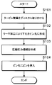
- FIG. 8 is a flowchart showing an embodiment of a stress improvement processing procedure of the steam turbine.
- the blade fork 11 of the turbine blade 10 and the disk fork 13 of the disk 12 are engaged, and the turbine blade 10 is attached to the rotor 1 (step S101).
- the blade fork 11 is formed with a pilot hole 16 having a diameter smaller than that of the pin hole 15.
- the disk fork 13 is formed with a lower hole 16 in the case of a new turbine, and a pin hole 15 in the case of replacement of the turbine rotor blade 10.
- the pin hole substantially formed in the disk fork 13 is the lower hole 16 in order to make the diameter of the pin hole larger than that of the turbine rotor blade 10 before replacement.
- step S102 a reaming process is performed on the lower hole 16 to increase the diameter to form the pin hole 15, and chips generated by the reaming process are removed as necessary.
- a stress improvement process is performed on the surface of the formed pin hole 15 by a laser peening apparatus to form a compressive stress region C (step S103).
- the chip removal operation can be executed in parallel with the stress improvement processing or after the stress improvement processing depending on the stress improvement processing. For example, in this laser peening, since it constructs, supplying a liquid to the construction object near the radiation point of a laser beam, it is possible to construct it while removing chips around the construction object.
- step S104 a pin is inserted into the pin hole 15 to couple the turbine rotor blade 10 to the disk 12 (step S104).
- This assembly procedure can be automatically performed by the control operation of the control unit 18.
- the compressive stress region C is formed on the inner surface of the pin hole, so that the tensile stress applied to the inner surface of the pin hole 15 during operation of the turbine can be suppressed.
- the steam turbine of the operation plant is in an environment where the contaminated steam from the reactor circulates to the turbine, so that the radiation dose is high and the operator cannot work on site for a long time.
- the construction head can be positioned and the construction remote operation can be performed, so that the control panel or the like can be arranged at a position away from the radiation source. As a result, it is possible to reduce exposure contamination and to perform a continuous operation for forming a compressive stress region.
- FIG. 9 is a diagram for explaining the configuration of the stress processing device 24 according to the second embodiment, and is a front view showing a case where stress is improved on the pin hole 15 of the disk 12. Since the configuration of the stress processing apparatus 24 of the second embodiment is the same as that of the stress processing apparatus shown in FIG. 2, detailed description thereof is omitted.
- a guide plate 59 having the same shape as the blade fork 11 is disposed at a position where the turbine rotor blade 10 is removed.
- the disk fork 13 and the guide plate 59 are positioned by a temporary pin and then peened on the inner surface of the pin hole 15 to form a compressive stress region C.
- the positioning of the pin hole 15 and the position of the construction head 38 is the same as that of the stress processing apparatus of the first embodiment, and thus the description thereof is omitted here.
- the compressive stress region is formed on the inner surface of the pin hole of the disk fork, so that the tensile stress applied to the inner surface of the pin hole during turbine operation can be suppressed.
- it is possible to prevent the occurrence of stress corrosion cracking on the inner surface of the pin hole at the joint between the moving blade and the disk of the steam turbine, and to improve the fatigue strength.
- a guide plate with the same shape as the blade fork is placed at the position where the turbine blade is removed. For this reason, when the construction head passes between the disk forks, the central axis is not shifted, and when construction is performed by laser peening, the liquid can be reliably supplied to the inner surface of the pin hole.
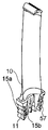
- FIG. 10A to FIG. 10C are views showing the turbine rotor blade 10 when a single product is constructed.
- 10A and 10B are perspective views of the turbine rotor blade, and
- FIG. 10C is a partial side view from the x direction.
- FIG. 11 is a perspective view showing the turbine rotor blade 10 when two sheets are stacked.
- FIG. 12 is a perspective view showing the configuration of the stress processing apparatus 60 according to the third embodiment and showing the stress processing apparatus 60 that applies stress improvement to the inner surface of the pin hole 15 of the removed turbine rotor blade 10.
- the turbine rotor blade 10 has semicircular holes 15a and 15b in the width direction. Three of these 15a and 15b are formed in the radial direction of the rotor 1, and constitute radical surfaces 57, respectively. And the pin hole 15 is formed of the mutual holes 15a and 15b by overlapping the adjacent turbine rotor blades 10 with each other.
- FIGS. 10A and 10B it is necessary to carry out the left and right twice to construct the semicircular holes 15a and 15b.
- the left and right holes 15 a and 15 b can be simultaneously constructed by arranging the adjacent turbine rotor blades 10 so that the pin holes 15 are coaxial. As a result, the number of constructions can be reduced by one.
- the pin holes 15 of the adjacent turbine rotor blades 10 are coaxially positioned and installed.
- the stress processing device 60 includes a guide plate 61, a radical surface block 62, an end tool block 63, and a clamp 64.
- the guide plate 61 has the same fork shape as the disk fork 13 and engages with the blade fork 11 of the turbine rotor blade 10.
- the radical surface block 62 receives one surface (for example, the surface on the hole 15a side) of the radical surface 57 of the blade fork 11.
- the end tool block 63 engages with the planting end tool 58 of the wing fork 11.
- the clamp 64 has a semicircular convex portion opposite to the radical surface 57, and this convex portion engages with a hole (for example, hole 15 b) on the other surface of the radical surface 57.
- the blade fork 11 is inserted into the guide plate 61 and simultaneously pressed against the radical surface block 62 and the end tool block 63.
- the blade fork 11 is constrained in three directions: two directions corresponding to the circumferential direction and the axial direction of the rotor, and the longitudinal direction of the turbine rotor blade 10.
- the clamp 64 is brought into contact with one surface (for example, the surface on the hole 15a side) of the radical surface 57 of the blade fork 11 by the air cylinder 65, and the turbine blade 10 is always fixed at the same position. It becomes possible.
- the guide plate 61, the radical surface block 62, the end tool block 63, and the clamp 64 are expressed as follows: “The removed turbine rotor blades are arranged in two directions corresponding to the circumferential direction and the axial direction of the rotor during assembly; It functions as a positioning portion that positions in three directions with the longitudinal direction of the blade.
- the stress processing device 60 includes a head unit 66, a height direction adjusting unit 67, a width direction adjusting unit 68, a head rotating unit 69, a head feeding unit 70, and a control unit 180. Since the head portion 66 has the same configuration as the head portion 36 of the first embodiment, detailed description thereof is omitted here.
- the height direction adjustment unit 67 adjusts the height direction H of the head unit 66.
- the width direction adjustment unit 68 adjusts the width direction S of the head unit 66.
- the head rotating unit 69 rotates the head unit 66.
- the head feeding section 70 moves the head section 66 in a direction P parallel to the direction corresponding to the central axis 27 of the rotor 1.
- the control unit 180 controls the height direction adjusting unit 67, the width direction adjusting unit 68, the head rotating unit 69, and the head feeding unit 70 at the same time, thereby constructing the inner surface of the pin hole 15 to form a compressive stress region. .
- the turbine rotor blade 10 in which the compressive stress region is formed is sequentially combined with the disk 12 of the rotor 1.
- the compressive stress region C is formed on the inner surface of the pin hole of the turbine rotor blade, so that the tensile stress applied to the inner surface of the pin hole 15 during operation of the turbine can be suppressed.
- it is possible to prevent the occurrence of stress corrosion cracking on the inner surface of the pin hole at the joint between the moving blade and the disk of the steam turbine, and to improve the fatigue strength.
- FIG. 13 is a perspective view illustrating a configuration of a stress processing apparatus 60 according to the fourth embodiment.
- This stress processing device 60 is an application of the stress processing device of the third embodiment, and is arranged by arranging two adjacent turbine blades 10 in a row and coaxially positioning the pin holes 15 of these turbine blades 10. To do. For this reason, the stress processing device 60 has two guide plates 61, radical surface blocks 62, end tool blocks 63, and clamps 64. Further, the head portion 66 needs to be longer than the head portion of the third embodiment so as to correspond to the two rows of turbine blades 10. In the present embodiment, two rows of turbine blades are simultaneously applied. However, the present invention is not limited to this, and three or more rows of turbine blades may be simultaneously applied.
- the same effects as those of the third embodiment can be obtained, and a plurality of rows of turbine blades can be simultaneously applied. As a result, the construction time can be shortened.
- FIG. 5 is a diagram showing a case where the spindle-shaped construction head 38 is inserted into the pin hole 15
- FIG. 14B is a diagram showing a case where the spindle-shaped construction head 38 is inserted into the pin hole 15.
- the construction head was positioned from the captured image using an image measurement program.
- the construction head 38 can be easily positioned at the position of the pin hole 15 without interference at the entrance of the pin hole 15.
- the photographed image may be copied on a monitor and the position deviation of the construction head may be corrected artificially by visual observation. In this case, a slight misalignment cannot be corrected, and the head tip 46 may interfere at the entrance of the pin hole 15.
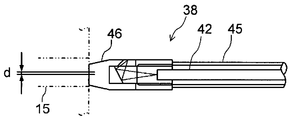
- the head tip 46 is formed in a spindle shape.
- the construction head 38 provided with the head tip 46 is positioned and inserted into the pin hole 15, the construction head 38 receives a force in the radial direction of the pin hole 15 even if a slight positional deviation occurs.
- the tubular member 45 bends due to the reaction force, and the construction head 38 follows the pin hole 15. Since this construction head 38 has a diameter of about 0.5 mm smaller than that of the pin hole 15 in advance, it can absorb an axial misalignment d of about 0.25 mm in the radial direction.
- the minimum spot diameter s at which the laser beam B is focused has the largest energy, and the stress improvement is about ⁇ 0.5 mm with respect to the radius of the pin hole 15. Has the expected tolerance. For this reason, it is possible to transmit the rotational power within a range in which a stress improvement effect can be obtained while absorbing a slight positional deviation (axial deviation d).
- FIG. 15A and 15B are enlarged cross-sectional views of the entrance / exit part of the pin hole 15.
- FIG. 15A is a view showing an inlet portion
- FIG. 15B is a view showing an outlet portion.
- the opening 46a Since the opening 46a is not completely inserted into the pin hole 15 at the entrance and exit of the pin hole 15, the liquid is diverted without being ejected only to the construction target position a. As a result, the amount of liquid supplied to the construction target position a decreases.
- the guide plates 80 and 81 are arranged in the vicinity of the inlet and outlet portions of the pin hole 15.
- the guide plates 80 and 81 have through holes 82 and 83 having the same diameter as the pin hole 15, and are arranged so that the central axes of the through holes 82 and 83 are coaxial with the central axis of the pin hole 15.
- the head tip 46 is inserted into the guide plate 80.
- the opening 46a reaches the position of the inlet of the pin hole 15, the liquid is supplied to the pin hole 15 and the through hole 82 and is directly ejected to the inlet of the pin hole 15 without being divided.
- the head tip 46 advances through the pin hole 15.
- the opening 46a reaches the outlet of the pin hole 15
- the liquid is supplied to the pin hole 15 and the through hole 83, and is directly ejected to the outlet of the pin hole 15 without being divided.
- the guide plates 80 and 81 are disposed at the inlet portion and the outlet portion of the pin hole 15, the liquid can be prevented from being diverted, and the liquid can be ejected to the inlet portion and the outlet portion. Effective cleaning is possible.
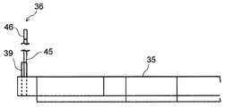
- FIG. 16A and 16B are enlarged views of main parts of the head unit 36 and the boom 35 of the stress processing device according to the seventh embodiment.
- FIG. 16A is a side view
- FIG. 16B is a front view.
- the configuration of the head portion 36 that simultaneously constructs a plurality of pin holes 15 arranged in the radial direction of the rotor 1 will be described.
- a plurality of pin holes 15 are formed at equal pitches in the radial direction of the rotor 1. Therefore, a plurality of construction heads 38 of the head portion 36 are arranged in the longitudinal direction of the boom 35 in correspondence with these pin holes 15 (see FIG. 16B). These construction heads 38 are simultaneously rotated by, for example, the head rotation driving unit 34 shown in FIG. 4 to enable simultaneous construction of a plurality of pin holes 15.
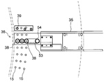
- FIG. 17A and 17B are enlarged views of main parts of the head unit 36 and the boom 35 of the stress processing apparatus according to the eighth embodiment.
- FIG. 17A is a side view
- FIG. 17B is a front view.
- the structure of the head part 36 which simultaneously constructs the plurality of pin holes 15 arranged in the circumferential direction of the rotor 1 will be described.
- the blade fork 11 and the disk fork 13 are thin in the tip direction, and the length of the pin hole 15 is also shortened accordingly. For this reason, when a plurality of pin holes are simultaneously constructed using the head portion of the seventh embodiment, a waiting time is caused in the construction of a pin hole having a short length.
- a plurality of pin holes 15 are formed at equal pitches in the circumferential direction of the rotor.
- a plurality of construction heads 38 of the head portion 36 are arranged in the width direction of the boom 35 so as to correspond to the pin holes 15 (see FIG. 17B). These construction heads 38 are simultaneously rotated by, for example, the head rotation driving unit 34 shown in FIG. 4 to enable simultaneous construction of a plurality of pin holes 15.
- Each construction head 38 is attached to a support member 85 having a rod-like structure.
- Each support member 85 is arrange
- a plurality of pin holes provided in the circumferential direction of the rotor can be simultaneously constructed. For this reason, the number of times of positioning and construction can be reduced. As a result, the work process and time for construction can be reduced, the waiting time for construction can be reduced, and the number of rotation operations of the head rotation drive unit can be reduced.
- the reamer hole 86 of the holder 35a for positioning the support member 85 of the construction head 38 at a predetermined angle corresponding to the circumferential pitch of the pin hole 15 to be constructed is processed in advance. .
- a plurality of holders 35a corresponding to different circumferential pitches of the pin holes 15 to be constructed are manufactured.
- a holder 35a corresponding to the pitch of the pin holes 15 to be constructed is selected, a support member 85 is attached to the holder 35a, and a reamer bolt 87 is inserted into the reamer hole 86, thereby positioning and fixing the support member 85.
- a plurality of holders corresponding to the circumferential pitches with different pin holes are manufactured, and a support member for the construction head is mounted on the holder corresponding to the pitch of the pin holes to be constructed from the holders. Install. Thereby, it is possible to construct the pin holes for any pin hole arrangement in any plant.
- the fork has three pin holes 15 arranged in the same radial direction in the same number, for example, three concentric circles having different radii in the embodiment.
- a holder 35a is provided that allows the position of the construction head 38 to be rearranged.
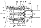
- 18A and 18B are enlarged views of main parts of the head unit 36 and the boom 35 of the stress processing device according to the second modification of the eighth embodiment.
- 18A is a side view
- FIG. 18B is a front view.
- the holder 35a has a plurality of assembly reamer holes 86 arranged in parallel with the radial direction of the plurality of predetermined rotors 1.
- the assembly reamer holes 86 are arranged along the longitudinal direction on both sides with respect to one construction head 38. Then, each construction head 38 is moved in the radial direction (arrow 88 direction) of the rotor 1 to match the position of the pin hole 15 to be constructed, and in this state, a reamer bolt 87 is inserted into the reamer hole 86 to position the support member 85. Fix it.
- the construction head is moved so as to match the position of the pin hole to be constructed, and the support member is positioned in that state. For this reason, it becomes possible to easily reassemble the construction head to the pin hole position to be constructed.
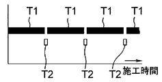
- FIG. 19A and 19B are diagrams for explaining a construction operation of the stress processing apparatus according to the ninth embodiment.
- FIG. 19A is a diagram showing a construction track in the case of a linear operation
- FIG. 19B is a diagram showing a construction time in the case of a linear motion.
- the stress processing device 24 (or 60) first drives and controls the head feed driving unit 33, and irradiates the laser in a straight line in the axial direction of the pin hole 15 (right to left in the drawing) at the laser irradiation time T1. Thereafter, the head rotation drive unit 34 is driven and controlled, and the laser beam is cut off at the laser cut-off time T2 to move the optical axis in the circumferential direction of the pin hole 15. Then, the head feed driving unit 33 is again driven and controlled, and laser is irradiated in a straight line in the axial direction of the pin hole 15 (from the left to the right in the drawing) at the laser irradiation time T1. Hereinafter, this construction operation is repeated to form a compressive stress region on the inner surface of the pin hole 15.
- the laser irradiation time T1 is a value obtained by dividing the axial length of the pin hole 15 by the moving speed of the laser beam.
- the laser cutoff time T2 is a value related to the aperture of the laser beam, for example, so that the compressive stress region can be uniformly formed on the inner surface of the pin hole 15 with a predetermined thickness.
- the laser beam is moved back and forth in parallel with the axial direction of the pin hole, so that a uniform compressive stress region can be formed on the inner surface of the pin hole.
- FIG. 20A and 20B are diagrams for explaining the construction operation of the stress processing apparatus according to the modification of the ninth embodiment.
- FIG. 20A is a diagram showing a construction track in the case of a spiral operation
- FIG. 20B is a diagram showing a construction time in the case of a spiral motion.
- the stress processing device 24 (or 60) drives and controls the head feed driving unit 33 and the head rotation driving unit 34, and irradiates the inner surface of the pin hole 15 in a spiral manner with the laser irradiation time T, so that the inner surface of the pin hole 15 is irradiated. A compressive stress region is formed.
- the laser irradiation time T is a value obtained by dividing the length of the laser beam moving spirally from the inlet portion to the outlet portion of the pin hole 15 by a predetermined pitch by the moving speed of the laser beam.
- the predetermined pitch is a value related to the aperture of the laser beam, for example, so that the compressive stress region can be uniformly formed on the inner surface of the pin hole 15 with a predetermined thickness.
- the laser irradiation is continuously moved in a spiral shape, so that a compressive stress region is uniformly formed on the inner surface of the pin hole, and the laser cut-off time does not occur and the construction time can be shortened. is there.
- the construction may be performed by switching the construction conditions depending on the material types of the turbine rotor blade 10 and the disk 12.
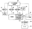
- FIG. 21 is a block diagram showing a configuration of a construction management system that performs construction management of the stress treatment device 24.
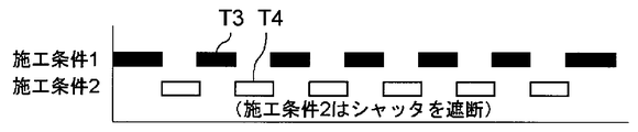
- 22A and 22B are diagrams for explaining a case where the construction conditions are switched according to the type of material in the stress processing device 24 that performs laser peening.
- FIG. 22A is a diagram in the case of constructing only one material
- FIG. 22B is a diagram in the case of constructing under different conditions.
- the construction management system includes a stress processing device 24 including a laser peening device 29, a construction condition input unit 90, a control panel 91, and a monitor 92.
- the construction condition input unit 90 depends on the amount of axial movement of the pin hole 15 as construction conditions, whether to construct only one material (the blade fork 11 or the disk fork 13) shown in FIGS. 22A and 22B, or the type of material. Enter information such as construction under construction conditions.
- the control panel 91 obtains the operation speed 94 and the operation range 95 of the construction based on the inputted construction condition information, and outputs the information to the control unit 18 of the stress processing device 24 and causes the monitor 92 to display the information.
- the construction condition input unit 90, the control panel 91, and the monitor 92 can be configured by, for example, a personal computer (hereinafter referred to as “personal computer”). That is, the construction condition input unit 90 corresponds to a personal computer keyboard and mouse, the control panel 91 corresponds to a personal computer body, and the monitor 92 corresponds to a personal computer display.
- control unit 18 drives and controls the rotor radial direction drive unit 31, the rotor tangential direction drive unit 32, the head feed drive unit 33, and the head rotation drive unit 34 to construct the inner surface of the pin hole 15. To do.
- the control panel 91 detects the moving distance by the time from the start of laser irradiation. When the axial movement position of the pin hole 15 by the stress processing device 24 reaches the target position (laser irradiation time T3), the control panel 91 outputs a laser stop command to the laser peening device 29 and blocks the laser light.
- laser cutoff time T4 when the next laser irradiation start position (laser cutoff time T4) is reached in a state where the laser beam is blocked, laser irradiation is started.
- FIG. 22B laser light is irradiated immediately after switching the laser irradiation conditions, and the laser light is moved to the next target position (laser irradiation time T3).
- the laser irradiation conditions can be switched according to the construction conditions, it is possible to construct the pin holes under different conditions depending on the material.
- the construction condition it is possible to switch the construction operation condition by inputting from the construction condition input unit 90 whether the construction is performed by the linear motion or the spiral motion shown in FIGS. 19A and 20A.
- the pin hole can be constructed under different operating conditions.
- the construction head 38 can be shared.
- FIGS. 23A and 23B are cross-sectional views of the main part of the construction head 38 of the stress processing apparatus according to the eleventh embodiment.
- FIG. 23A is a diagram showing the front
- FIG. 23B is a diagram showing the side.
- FIG. 24 is a front view for explaining the rotation state of the construction head 38 shown in FIGS. 23A and 23B.
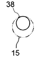
- the diameter of the construction head 38 is formed to be smaller than the minimum diameter of the pin holes 15 for construction.
- the control unit 18 drives and controls the rotor radial direction drive unit 31 and the rotor tangential direction drive unit 32 so that the construction head 38 moves circularly according to the diameter of the pin hole 15 to be constructed.
- the control unit 18 drives and controls the head rotation driving unit 34 in the normal direction connecting the center 98 of the construction head 38 and the center 99 of the pin hole 15.
- the construction head 38 can eccentrically move the inner surface of the pin hole 15.
- the laser beam B is controlled so that it is always applied to the position where the construction head 38 is in contact with the pin hole 15.
- FIGS. 25A and 25B are cross-sectional views of the main part of the construction head 38 of the stress processing apparatus according to the first modification of the eleventh embodiment.
- FIG. 25A is a diagram showing the front
- FIG. 25B is a diagram showing the side.
- FIG. 26 is a front view for explaining the rotation state of the construction head 38 shown in FIGS. 25A and 25B.
- a gap is generated between the pin hole 15 and the construction head 38. For this reason, when vibration or impact is applied to the stress processing apparatus, the spot diameter of the laser beam B increases, exceeding the tolerance of the stress improvement range, and the stress improvement effect may not be obtained.
- a spacer 110 corresponding to the gap between the pin hole 15 and the construction head 38 is provided to fill this gap.
- the spacer 110 is formed in a crescent-shaped cross section and is detachably attached to the outer peripheral surface of the construction head 38 to adjust a gap with the pin hole 15.
- the spacer 110 can be fixed to the construction head with a reamer bolt, for example.
- a plurality of spacers 110 can be attached.
- the control unit 18 drives and controls the rotor radial direction drive unit 31, the rotor tangential direction drive unit 32, and the head rotation drive unit 34, as in the eleventh embodiment.
- the construction head 38 can favorably eccentrically move the inner surface of the pin hole 15. During this eccentric movement, the laser beam B is controlled so that it is always applied to the position where the construction head 38 is in contact with the pin hole 15.
- a spacer is attached to the construction head and the gap with the pin hole is adjusted.
- the spacer of the shape according to the diameter of a pin hole can be attached to the outer peripheral surface of a construction head, without replacing the construction head which is an optical system component. As a result, even a beginner can easily attach the spacer.
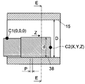
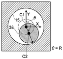
- FIG. 27 is a cross-sectional view for explaining the operation control of the construction head 38 of the stress processing apparatus according to the second modification of the eleventh embodiment.
- FIG. 28 is a cross-sectional view showing the EE cross section of FIG.
- the construction head 38 (construction target position a) is located between the center C1 of the pin hole 15 and the construction head 38.
- the construction head 38 can be eccentrically moved along the inner peripheral surface of the pin hole 15 while facing the normal direction connecting the center C2.
- the construction head is controlled in the X, Y, Z, and R axis directions to adjust the gap with the pin hole. For this reason, regardless of the diameter of the pin hole, the construction head 38 can favorably eccentrically move the inner surface of the pin hole 15. During this eccentric movement, the laser beam can be controlled so that it is always applied to the position where the construction head 38 is in contact with the pin hole 15.
- Embodiment 12 In the stress processing apparatus 24, the neutral or alkaline liquid L is ejected to the inner surface of the pin hole 15 to be constructed. Therefore, if the liquid L is left as it is, rust is generated in the left part. For this reason, it is necessary to dry the pin hole 15 after construction or the gap between the turbine rotor blade 10 and the disk 12 and the periphery thereof to prevent the generation of rust.
- the liquid L adhering to the turbine rotor blade 10 or the disk 12 basically adheres to these surfaces and flows down.
- the turbine rotor blade 10 and the disk 12 are connected circumferentially, and the blade fork 11 and the disk fork 13 have a clearance of about 0.4 mm.
- the liquid L may accumulate in the gap portion 125. It has been difficult in the past to insert a drying head directly into the narrow gap portion 125 and spray a dry gas. Similarly, the liquid L may accumulate on the inner surface of the pin hole 15 due to surface tension.
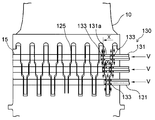
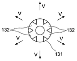
- FIGS. 29A and 29B are diagrams for explaining a drying device 130 for drying the gap 125 between the turbine rotor blade 10 and the disk 12 according to the twelfth embodiment.
- 29A is a front view of the turbine rotor blade 10 and the disk 12
- FIG. 29B is an arrow view of the drying head 131 viewed from the X direction.
- the drying apparatus 130 includes a gas supply unit (not shown) for supplying a dry gas, a head moving unit (not shown), a drying head 131, and an O-ring 133.
- the gas supply unit heats and drys a gas containing 80% of nitrogen with a heater, and supplies the dry gas from which moisture has been removed to the drying head 131.
- the head moving unit moves the drying head 131 in the axial direction.
- the drying head 131 is formed in a cylindrical shape, and has a plurality of through holes 132 shown in FIG. 29B on the circumferential surface of the distal end portion 131a.
- the drying heads 131 are arranged in a number corresponding to the number of pin holes 15 formed in the fork, that is, three in the embodiment.
- the three drying heads 131 are arranged in three stages according to the length of the pin hole 15 as shown in FIG. 29A, and move on the inner surface of the pin hole 15 in this arrangement state. Thereby, all the drying heads 131 that move on the inner surface of the pin hole 15 can reach the position of the gap portion 125 at the same time.
- the through holes 132 are arranged, for example, radially in six directions on the circumferential surface of the drying head 131 and at two positions on the tip 131a of the drying head 131, respectively.
- the distance between these two through holes 132 is set to a length equal to the length of the pin hole 15 to be constructed.
- These through holes 132 eject the dry gas supplied from the gas supply unit from the inside of the drying head 131 to the inner surface of the pin hole 15.
- O-rings 133 are provided on each of the circumferential surfaces of the drying head 131 in the axial direction so as to sandwich the through hole 132 (see FIG. 29A).
- the drying head 131 moves in the axial direction on the inner surface of the inserted pin hole 15.
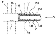
- the O-ring 133 seals the inner surface of the pin hole 15. For this reason, the dry gas V supplied from the through hole 132 is ejected to the outside only through the gap portion 125.
- FIG. 30 is a cross-sectional view showing a drying head 135 according to Modification 1 of Embodiment 12.
- the drying head 135 is formed in a cylindrical shape and has a plurality of through holes 136 on the circumferential surface.
- a plurality of these through holes 136 are arranged on the same circumference and in the axial direction of the drying head 135.
- the through hole 136 is formed in an oblique hole of about 45 degrees so as to eject the dry gas V obliquely forward from the inside of the drying head 135. Since the pin hole 15 is parallel to the rotation center of the rotor 1 and also parallel to the floor surface, the liquid L remains attached to the inner surface of the pin hole 15, so that the liquid L is scattered forward of the drying head 135. This is to make it possible.
- the dry gas can be ejected to the inner surface of the pin hole obliquely forward of the drying head. For this reason, the dry gas flows in front of the inner surface of the pin hole, and the liquid adhering to the inner surface of the pin hole can be accurately removed, and the generation of rust can be prevented.
- FIG. 31 is a cross-sectional view illustrating a drying head 137 according to the second modification of the twelfth embodiment.
- the drying head 137 includes a fixed propeller portion 138, a rotating portion 139, a connection ring 140, and a tubular member 141.
- the fixed propeller unit 138 has a propeller-like blade 142 fixed inward to the tip of the drying head 137.
- the blades 142 are arranged to receive the supplied dry gas V from the front.
- the rotating part 139 is formed in a cylindrical shape covering the blade 142 and has a through hole 143 on the circumferential surface. Similar to the through hole 136 of the first modification, the through hole 143 is formed in an oblique hole of about 45 degrees so that the dry gas V is ejected obliquely forward from the inside of the drying head 137.
- connection ring 140 rotatably connects the rotating part 139 to the tubular member 141.
- the connection ring 140 is composed of, for example, a bearing that reduces frictional resistance.
- the blade 142 When the dry gas V supplied from the tubular member 141 is vigorously ejected to the blade 142 at a pressure of about 0.5 MPa, the blade 142 receives a reaction force. Due to this reaction force, a rotational force is transmitted to the rotating portion 139, and the dry gas V can be ejected to the entire inner surface of the pin hole 15 of the drying head 137 through the through-hole 143 while rotating by the rotational force.
- the dry gas can be ejected from the rotating rotating part to the inner surface of the pin hole obliquely forward of the drying head. For this reason, the dry gas flows in front of the inner surface of the pin hole, and the liquid adhering to the inner surface of the pin hole can be accurately removed, thereby preventing the occurrence of rust.
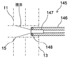
- FIG. 32 is a cross-sectional view illustrating an inspection head 145 according to the thirteenth embodiment.
- the pin hole 15 is usually formed with a diameter of 10 mm to 17 mm.
- the maximum width of the blade fork 11 and the disk fork 13 is 300 mm or more, the illuminance is low in the pin hole 15 and it is difficult to visually inspect the entire pin hole 15.
- an inspection head 145 that can inspect the entire inside of the pin hole 15 is provided.
- the inspection head 145 includes a tubular member 146, a fiberscope 147, and an illumination unit 148.
- the tubular member 146 has a fiberscope 147 disposed therein.
- An illumination unit 148 is disposed at the tip of the tubular member 146.
- the fiberscope 147 generates a viewable region that is visible in front of the tubular member 146.
- the fiberscope 147 is connected to a monitor (not shown) and enables video display.
- the illuminating unit 148 includes ring-shaped illumination, and irradiates the inner surface of the pin hole 15 in the visual field area in front of the tubular member 146.
- the inspection head 145 When the inspection head 145 is inserted into the pin hole 15, the inner surface of the pin hole 15 in the front field of view is irradiated, thereby enabling inspection by an operator.
- the entire pin hole can be visually inspected.
- FIG. 33 is a sectional view showing the combined head 150 according to the fourteenth embodiment.
- the combined head 150 includes a tubular member 151, a fiber scope 152, and an illumination unit 153.
- the tubular member 151 has a fiberscope 152 disposed therein.
- a gap 154 is formed between the inner surface of the tubular member 151 and the fiber scope 152.
- the tubular member 151 is connected to the gas supply unit, and ejects the dry gas V to the outside through the gap 154. For this reason, the clearance 154 on the distal end side of the tubular member 151 is formed in a narrow structure.
- the fiber scope 152 generates a visible field area in front of the tubular member 151.
- the fiberscope 152 is connected to a monitor (not shown) and enables video display.
- An illumination unit 153 is disposed at the tip of the fiber scope 152.
- the illumination unit 153 includes ring-shaped illumination, and irradiates the inner surface of the pin hole 15 in the visual field area in front of the tubular member 151.
- the dry gas V is jetted into the pin hole 15 from the gap 154 between the tubular member 151 and the fiber scope 152. Simultaneously with this ejection, the inner surface of the pin hole 15 in the front field of view is irradiated, enabling inspection by the operator's visual inspection.
- the inside of the pin hole can be simultaneously dried while visually inspecting the entire pin hole.
- the liquid L ejected during laser peening is scattered from the opposite direction of the pin hole 15 on the head insertion side.
- a recovery unit that recovers cutting material and liquid is provided.
- FIG. 34 is a diagram illustrating the collection unit 160 according to the fifteenth embodiment.
- the collection unit 160 includes a flange 161, a guide pipe 162, an O-ring 163, and a pump (not shown).
- the flange 161 has a hole 164 to which the guide pipe 162 is attached.
- the hole 164 is formed to have the same diameter as the pin hole 15.
- the guide pipe 162 is connected to the pump and sucks the liquid L by the suction operation of the pump.
- the O-ring 163 is disposed on the side surface of the flange 161 so as to surround the hole 164.
- the flange 161 and the O-ring 163 are attached to the side of the fork so that the hole 164 is aligned with the outlet of the pin hole 15 and sucked with a pump, so that the liquid L scattered during construction is taken into the guide pipe 162.
- the liquid remaining in the pin hole can be reduced, and the work time in the next work process, for example, the drying process can be shortened.
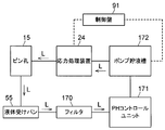
- FIG. 35 is a block diagram showing a configuration of a reuse system according to the sixteenth embodiment for collecting and reusing the liquid L.
- the reuse system includes a stress processing device 24 including a laser peening device 29, a control panel 91, a liquid receiving pan 55, a filter 170, a PH control unit 171, a pump storage tank 172, and a control panel 91.
- a stress processing device 24 including a laser peening device 29, a control panel 91, a liquid receiving pan 55, a filter 170, a PH control unit 171, a pump storage tank 172, and a control panel 91.
- the solid line indicates the flow of the liquid L
- the dotted line indicates the connection path of the control system.
- the liquid receiving pan 55 stores the liquid L dropped from the pin hole 15 and supplies it to the filter 170.
- the filter 170 has a function of filtering impurities and oil remaining in the pin holes 15, a minute amount of metal powder sublimated by laser peening, foreign matters mixed in from the outside, and the like. It should be noted that the filter 170 needs to be periodically replaced because there is a possibility of clogging when a predetermined amount of foreign matter adheres abnormally.
- the PH control unit 171 has a function of adjusting the pH of the filtered liquid L.
- the PH of the liquid L has an effect of making the turbine rotor blade 10 and the disk 12 less likely to rust as the alkalinity is closer to alkalinity.
- the pump liquid storage tank 172 has a pump (not shown), sucks up the liquid L whose pH has been adjusted, and supplies it to the stress processing device 24. In addition, when the liquid L of the pump storage tank 172 becomes a predetermined level or less, it is necessary to replenish the liquid.
- the control panel 91 controls the stress treatment device 24 based on the construction conditions, and drives and controls the pump of the pump liquid storage tank 172.
- Liquid L is stored in a pump storage tank 172, pumped up by a pump, passes through a flow rate detection valve, a hose 48, and a boom 35 (not shown), and is ejected from an opening 46a of the construction head 38.
- the liquid L ejected from the opening 46a falls to the liquid receiving pan 55 through the pin hole 15, and is further sucked by the filter 170 to remove foreign matters.
- the pH of the liquid L is adjusted by the PH control unit 171, sucked up by the pump, and circulated to the pump liquid storage tank 172.
- the liquid ejected into the pin hole is filtered and adjusted in pH, and then supplied again to the stress processing apparatus, so that the liquid can be reused. As a result, resource depletion can be prevented.
- FIG. 36 is a diagram illustrating a configuration of a construction system 175 according to the seventeenth embodiment.
- stress processing devices for example, the stress processing devices 24a to 24c or the stress processing devices 24d, which have the same function as the above-described stress processing device 24
- a plurality of 24e are arranged. Then, by the control panel 91, these stress processing devices construct each of the plurality of pin holes 15 at the same timing to form a compressive stress region.
- a stress processing apparatus for example, stress processing
- stress processing having the same mechanism as the above-described stress processing apparatus 24 at a position where the disk 12a of the final stage on the turbine side and the disk 12b of the final stage on the collector side face each other.
- a plurality of devices 24a and 24d or stress treatment devices 24c and 24e) are arranged.
- the control panel 91 forms a plurality of pin holes 15 at the same timing in these stress processing devices, thereby forming a compressive stress region.
- this construction system 175 the stress processing devices 24a to 24e are arranged in combination. Then, the control panel 91 may be used to construct the plurality of pin holes 15 at the same timing to form the compressive stress region.
- This construction system is “a construction system in which a plurality of stress processing devices are installed at different positions on the same circumference of the rotor and at least one position of the disk on the turbine side and the disk on the collector side facing each other”. Function as.
- a plurality of stress treatment devices are arranged in combination, and a plurality of pin holes are respectively constructed to form a compressive stress region. For this reason, simultaneous construction becomes possible by one rotation control, and construction time can be reduced.
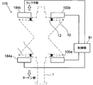
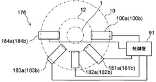
- FIGS. 37A and 37B are diagrams illustrating a configuration of a construction system 176 according to the eighteenth embodiment.
- FIG. 37A is a top view and
- FIG. 37B is a side view.
- the construction system 176 includes reamer processing devices 100a and 100b, construction devices 181a and 181b, drying devices 182a and 182b, inspection devices 183a and 183b, pin assembly devices 184a and 184b, and a control panel 91.
- the reamer processing devices 100a and 100b function as a processing unit that performs reamer processing simultaneously on a turbine rotor blade having a blade fork and a rotor disk having a disk fork with which the blade fork is engaged.
- the construction apparatuses 181a and 181b form a compressive stress region on the inner surface of the pin hole 15 by laser peening.
- the construction apparatuses 181a and 181b are “similar to the laser peening apparatus 29 shown in FIG. 5 in the case of laser peening construction.
- the construction apparatuses 181a and 181b rotate the rotor to bring the disk into a predetermined position.
- a rotor rotating portion to be positioned, and a working portion that forms a compressive stress region by peening the inner surface of the pin hole of the blade fork and the inner surface of the pin hole of the disk fork at the predetermined position.
- a stress processing apparatus that includes a jetting unit that jets liquid into the pin hole.
- the drying devices 182a and 182b perform a work of blowing away cutting material, liquid, or other foreign matters remaining in the pin hole 15 after laser peening.
- the drying devices 182a and 182b are the same as the drying device 130 shown in any of FIGS. 29A, 29B, 30 and 31.
- the drying devices 182a and 182b function as a “drying unit that dries the liquid sprayed into the pin holes”.
- Inspection devices 183a and 183b confirm foreign matter and construction range on the inner surface of the pin hole 15 after laser peening.
- the inspection apparatuses 183a and 183b are the same as the inspection apparatus including the inspection head 145 shown in FIG.
- the inspection devices 183a and 183b function as a “recognition unit that captures an image of a compressive stress region formed in the pin hole and recognizes the compressive stress region based on the image”.
- the pin assembling apparatuses 184a and 184b perform operations for assembling the turbine rotor blade 10 and the disk 12 by inserting pins into the pin holes 15 of the blade fork 11 and the disk fork 13 in which the compressive stress region is formed.
- the pin assembling devices 184a and 184b function as “an assembling portion for assembling the turbine rotor blade and the disk”.
- the devices 100a and 181a to 184a are arranged at different positions on the same circumference of the disk 12a in the final paragraph. Then, the control panel 91 performs drive control and work management of these devices 100a, 181a to 184a. The control panel 91 simultaneously performs a plurality of different operations of these devices 100a, 181a to 184a.
- the devices 100a, 181a to 184a and 100b, 181b to 184b are arranged at different positions on the same circumference of the disks 12a and 12b in the final paragraph.
- devices 100a and 100b, 181a and 181b, 182a and 182b, 183a and 183b, 183a and 183b, and 184a and 184b having the same function are arranged at positions where the turbine-side disk 12a and the collector-side disk 12b face each other.
- the control panel 91 performs drive control and work management of these devices 100a, 181a to 184a and 100b, 181b to 184b.
- the control panel 91 simultaneously performs a plurality of different operations of these devices 100a, 181a to 184a and 100b, 181b to 184b.
- This construction system 176 includes: “a turbine rotor blade having a blade fork and a rotor disk having a disk fork with which the blade fork is engaged; a processing portion that simultaneously reams the rotor; Rotating the rotor rotating portion to be positioned at a predetermined position, and forming a compressive stress region by peening the inner surface of the pin hole of the blade fork and the inner surface of the pin hole of the disc fork at the predetermined position.
- a stress processing device comprising: a construction section to perform; a spray section for spraying liquid into the pin hole; a drying section for drying the liquid sprayed into the pin hole; and a section formed in the pin hole.
- An image of a compressive stress region is taken, and a recognition unit that recognizes the compressive stress region based on the image, the turbine rotor blade, and the disk are assembled.
- An assembly part that stands, and each part is arranged at a different position on the same circumference of the rotor, or each part is arranged at a different position on the same circumference of the rotor.
- the disk and the disk on the collector side function as a construction system that arranges the parts having the same function.
- the compressive stress region is formed in the pin hole using the stress processing device, the occurrence of stress corrosion cracking on the inner surface of the pin hole at the joint between the moving blade of the steam turbine and the disk is prevented.
- the fatigue strength can be improved.
- the apparatuses for performing different operations for forming the compressive stress region are combined and arranged at different positions on the same circumference of the disk or at positions facing the disk to perform each operation. For this reason, each work can be performed simultaneously, and the work time and the number of positioning operations can be reduced.
- control panel 91 has a construction record function for recording a laser irradiation history 91a and a device movement history 91b, and displays these history 91a and 91b on a monitor 92, and construction management record information 91c based on these histories. Create and record.
- control panel 91 detects the operation speed 94 and the operation range 95 of the construction, detection of the laser peening device 29 (for example, detection of insufficient laser power, etc.), detection of the liquid flow rate of the pump in the pump storage tank 172, and construction. Perform range detection.
- the control panel 91 has a construction management interlock function that stops driving the stress processing device 24 and displays the abnormal part on the monitor 92 when there is an abnormality in these detection results.
- the liquid flow rate is detected by a flow rate detection valve. Therefore, when the liquid flow rate is less than the specified amount, it is considered that impurities and foreign matters cannot be removed at the laser light irradiation position and the laser power falls below the specified condition. For this reason, when the flow rate is reduced, it is necessary to instruct the stress processing device 24 to display the occurrence of abnormality on the monitor 92.
- the present embodiment has the above-described effects and has a construction management interlock function for detecting the abnormality and stopping the driving of the stress processing apparatus, so that the safety of the apparatus can be improved.
- a plurality of stress processing devices are arranged at different positions on the circumference of the disk 12a shown in the seventeenth embodiment, or at positions where the turbine-side disk 12a and the collector-side disk 12b face each other, and construction is performed simultaneously.
- control panel 91 shown in FIG. 21 has a construction recording function for each stress processing apparatus, and the above information can be centrally managed.
- the control panel 91 can also have a pacemaker function for obtaining a mutual work completion predicted time and displaying the predicted time on the monitor 92 and a display function for displaying a work performance for the target process.
- the present embodiment has the above-described effects and has a pacemaker function for predicting the completion of mutual work, so that work efficiency can be improved.
- FIG. 38 is a cross-sectional view of the main part of the head distal end portion 46 of the stress processing apparatus according to the twentieth embodiment.
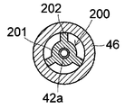
- FIG. 39 is a cross-sectional view showing the XX cross section of FIG.
- FIG. 40 is a perspective view showing the support portion 200 shown in FIG.
- the tip of the optical fiber 42 vibrates with the force of the water flow, and the laser light is subjected to construction. It will shift from the position a. Further, in order to prevent this vibration, if a small amount of liquid is injected into the tubular member 45, the momentum is weakened and a liquid film due to this liquid is not generated well, and the laser energy is sealed only on this liquid film. Can not.
- a support portion 200 that supports the tip of the optical fiber 42 is fixed in the head tip 46.
- the support portion 200 is disposed at equal intervals in the circumferential direction of the support member 201 and the support member 201 that supports the core wire 42a of the optical fiber 42, and couples the support member 201 and the inner peripheral surface of the head tip portion 46.
- it includes three coupling members 202.
- the support member 201 and the coupling member 202 are integrally formed.
- the number of coupling members 202 is not limited to three, and may be two or four or more.
- the center member 201 has a length in the longitudinal direction that is the same as the length in the longitudinal direction of the coupling member 202 and is formed in a hollow cylindrical shape, and has an inner axis with the core wire 42a of the optical fiber 42 as the center axis. Support by inserting into.
- Each of the coupling members 202 is formed of a rectangular parallelepiped, and is fixed to three points in the head distal end portion 46. A gap is formed between the coupling members 202 so that liquid can flow therethrough.
- the support portion 200 is fixed to the head tip portion 46, when the head tip portion 46 rotates, it rotates together with the head tip portion 46. At this time, the optical fiber 42 does not rotate while being supported by the support portion 200.
- the support unit 200 includes a support member 201 that supports the optical fiber, and a plurality of coupling members 202 that are provided around the support member 201 and that couple the support member 201 and the inside of the pin hole. The liquid ejected from the ejecting section can be circulated through the gap formed between the coupling members 202.
- the tip of the optical fiber is supported by the support portion fixed to the head tip.
- a large amount of liquid can be ejected into the tubular member, a good liquid film can be produced, and laser energy can be sealed only in this liquid film, and laser peening can be applied to the construction target position on the inner surface of the pin hole.
- a compressive stress region can be formed.
- the opening 46a formed in the head tip 46 is preferably elliptical because the laser beam B emitted from the reflection mirror 47 is elliptical. Further, for example, the long diameter of the opening 46a (the diameter in the longitudinal direction of the head tip 46) is 3 to 10 [mm], and the short diameter (the diameter in the short direction of the head tip 46) is 2 to 6 [mm]. mm] is preferable.
- the invention of the present application is not limited to the above-described embodiment.
- it is possible to increase the height of industrial products such as fastener holes (rivet holes) of structures, for example, aircraft bodies, oil ejection holes of diesel engine shafts, and axles of vehicles. It can be used for measures against cycle fatigue and stress corrosion cracking of mold cooling holes.
- the present invention is not limited to this, and the stress treatment can be performed even in the liquid.
- the present invention is not limited to the above-described embodiment, and the constituent elements may be modified without departing from the scope of the invention in the implementation stage.
- various inventions can be configured by appropriately combining a plurality of components disclosed in the embodiment. For example, some components may be deleted from all the components shown in the embodiment.
- constituent elements over different embodiments may be appropriately combined.
- Construction part (laser peening apparatus), 30 ... Base, 31 ... Rotor radial direction drive part, 32 ... Rotor tangential direction drive part, 33 ... Head Feed drive unit, 34 ... head rotation drive unit, 35 ... boom, 35a ... holder, 36 ... head unit, 37 ... side surface, 38 ... construction head, 39 ... imaging unit, 40 ... laser oscillator, 41 ... race Optical adjustment part 42 ... Optical fiber 43 ... Liquid feeding part 45 ... Tubular member 46 ... Head end part 46a ... Opening part 47 ... Reflecting mirror 48 ... Hose 49 ... Sleeve 50 ... Support member 51 ... Groove, 52 ... Rotation drive motor, 53 ... Timing belt, 54 ...
- wing member, 202 Wings
- a Construction target position
- B Laser light
- C Compressive stress region
- d Axial misalignment
- H Height direction
- L Liquid
- P Parallel direction
- s Minimum spot diameter, S ... width direction, T, T1, T3 ... laser irradiation time, T2, T4 ... laser cutoff time, V ... dry gas.
Landscapes
- Engineering & Computer Science (AREA)
- Mechanical Engineering (AREA)
- General Engineering & Computer Science (AREA)
- Physics & Mathematics (AREA)
- Optics & Photonics (AREA)
- Plasma & Fusion (AREA)
- Chemical & Material Sciences (AREA)
- Materials Engineering (AREA)
- Turbine Rotor Nozzle Sealing (AREA)
- Laser Beam Processing (AREA)
- Other Surface Treatments For Metallic Materials (AREA)
Abstract
Description
以下、実施形態について図面を参照しながら説明する。図1A~図1Cはタービン動翼10とディスク12を同時にリーマ加工することを説明するための図である。図1Aがタービン動翼10とディスク12の結合構造を示す正面図で、図1Bが側面図で、図1Cが図1BのX部拡大図である。図2は、実施形態1の応力処理装置24の構成を説明するための図で、タービン動翼10とディスク12の結合構造のピン孔15に応力改善を施す場合を示す正面図である。図3は、図2をA方向から見た構成を示す矢視図である。図4は、図2に示したヘッド部を示す拡大図である。なお、以下の図において、同様の構成部分については同一符号を付記する。
図9は、実施形態2に係る応力処理装置24の構成を説明するための図で、ディスク12のピン孔15に応力改善を施す場合を示す正面図である。この実施形態2の応力処理装置24の構成は、図2に示した応力処理装置と同様の構成であるので、詳細な説明を省略する。
次に、ロータ1から取り外したタービン動翼10にピーニングを施す場合を説明する。図10A~図10Cは、単品施工する場合のタービン動翼10を示す図である。図10A、図10Bはタービン動翼の斜視図で、図10Cはx方向からの部分側面図である。図11は、2枚重ねて施工する場合のタービン動翼10を示す斜視図である。図12は、実施形態3に係る応力処理装置60の構成を説明するための図で、取り外したタービン動翼10のピン孔15内面に応力改善を施す応力処理装置60を示す斜視図である。
図13は、実施形態4に係る応力処理装置60の構成を示す斜視図である。この応力処理装置60は、実施形態3の応力処理装置を応用したものであり、隣接するタービン動翼10を2列配置し、これらタービン動翼10のピン孔15を同軸上に位置決めして施工する。このため、応力処理装置60は、ガイドプレート61、ラジカル面ブロック62、端具ブロック63、クランプ64を2台ずつ有する。また、ヘッド部66は、2列のタービン動翼10に対応させて、実施形態3のヘッド部より長くする必要がある。なお、本実施形態では2列のタービン動翼を同時に施工したが、これに限らず3列以上のタービン動翼を同時に施工することも可能である。
図14A、図14Bは、実施形態5に係る応力処理装置の施工ヘッド38の断面図である。図14Aは紡錘形状の施工ヘッド38でピン孔15に挿入する場合、図14Bは紡錘形状の施工ヘッド38でピン孔15に挿入された場合を示す図である。
図15A、図15Bは、ピン孔15の出入口部の拡大断面図である。図15Aは入口部、図15Bは出口部を示す図である。
図16A、図16Bは、実施形態7に係る応力処理装置のヘッド部36とブーム35の要部拡大図である。図16Aは側面、図16Bは正面を示す図である。本実施形態では、ロータ1の半径方向に配置された複数のピン孔15を同時に施工するヘッド部36の構成を説明する。
図17A、図17Bは、実施形態8に係る応力処理装置のヘッド部36とブーム35の要部拡大図である。図17Aは側面、図17Bは正面を示す図である。本実施形態において、ロータ1の円周方向に配置された複数のピン孔15を同時に施工するヘッド部36の構成を説明する。
ピン孔15の配列位置は、ロータ1の半径方向の位置と、円周上のピン孔15のピッチとによって様々な配列が考えられる。このため、異なるピン孔の配列の場合には、図17A、図17Bに示したホルダ35aの施工ヘッド取り付け位置を、使用するロータ1に合せて交換することで対応が可能とする。
また、同一プラントにおいて、フォークにはピン孔15が複数段の円周状に同じ数、例えば、実施形態では半径の異なる3つの同心円の円周状で同一半径方向に3つ配列されている。
図19A、図19Bは、実施形態9に係る応力処理装置の施工動作を説明するための図である。図19Aは直線動作の場合の施工軌道を示す図、図19Bは直線動作の場合の施工時間を示す図である。
図20A、図20Bは、実施形態9の変形例に係る応力処理装置の施工動作を説明するための図である。図20Aは螺旋動作の場合の施工軌道を示す図、図20Bは螺旋動作の場合の施工時間を示す図である。
レーザピーニング装置29では、タービン動翼10とディスク12の素材の種類によって施工条件を切り替えて施工を行う場合がある。
レーザピーニングにおいて、ピン孔15に応力改善する際に、ピン孔15の径が異なっても施工ヘッド38を共用する場合について説明する。実施形態1に示した施工ヘッド38はユニット構成とした。しかし、この構成では交換する部分が大きく、複数のユニットを所持するのは困難が伴う。
図25A、図25Bは、実施形態11の変形例1に係る応力処理装置の施工ヘッド38の要部断面図である。図25Aは正面を示す図で、図25Bは側面を示す図である。図26は、図25A、図25Bに示した施工ヘッド38の回転状態を説明するための正面図である。
図27は、実施形態11の変形例2に係る応力処理装置の施工ヘッド38の動作制御を説明するための断面図である。図28は、図27のE-E断面を示す断面図である。
X=(D-d)÷2×cosθ
Y=(D-d)÷2×sinθ
Z=P×N+P×θ÷360
C1:ピン孔15の中心位置(基準位置)(基準座標(0,0,0)))
C2:施工ヘッドの中心位置(座標(X,Y,Z))
D:ピン孔15の直径
d:施工ヘッド38の直径
θ:ピン孔15方位
P:1回転当たりの施工ヘッド38の送りピッチ
N:施工ヘッド38の回転数
X,Y,Z:中心位置C1から中心位置C2までのX、Y、Z軸方向の距離
R:ヘッドの回転軸角度(ピン孔中心C1の真上を0度とした時計回り方向の角度)
応力処理装置24では、中性またはアルカリ性の液体Lを施工対象のピン孔15内面に噴出する。従って、この液体Lが残留したまま放置されると、その放置された部分に錆が発生する。このため、施工後のピン孔15またはタービン動翼10とディスク12の隙間部およびこれらの周囲を乾燥し錆の発生を防止する必要がある。
次に、ピン孔15内面を乾燥する乾燥ヘッド135について説明する。
図31は、実施形態12の変形例2に係る乾燥ヘッド137を示す断面図である。
次に、ピン孔15内面に圧縮応力領域が形成された後に、ピン孔15内面を検査する場合について説明する。
次に、乾燥作業とピン孔15内面検査を併用する場合について説明する。
次に、ピン孔15に供給された切削材や液体を回収する回収部について説明する。
次に、レーザピーニング時に噴出する液体Lの回収、再利用するシステムについて説明する。
図36は、実施形態17に係る施工システム175の構成を示す図である。
図37A、図37Bは、実施形態18に係る施工システム176の構成を示す図である。図37Aは上面図、図37Bは側面図である。
次に、施工管理インターロック機能、ペースメーカ機能について説明する。なお、これらの機能を実現する施工管理システムは、図21に示したシステム構成と同様なので、図21を用いて説明する。
図38は、実施形態20に係る応力処理装置のヘッド先端部46の要部断面図である。図39は、図38のX-X断面を示す断面図である。図40は、図38に示した支持部200を示す斜視図である。
Claims (15)
- 構造体に形成された孔内をレーザ照射するピーニングを施し、前記孔内に圧縮応力領域を形成するヘッド部と、前記レーザを前記ヘッド部に導光する光ファイバを有するレーザ部と、前記孔内に液体を噴射する噴射部と、前記噴射された液体を流通可能に前記光ファイバを支持し、かつ前記ヘッド部内に固定される支持部と、を備える施工部
を具備する応力処理装置。 - 前記構造体は、翼フォーク及びディスクフォークであり、
前記孔は、前記翼フォーク及び前記ディスクフォークに形成されたピン孔であり、
前記翼フォークを有するタービン動翼と、前記翼フォークと係合して組み立てられ、かつ前記翼フォークと互いに貫通する前記ピン孔が形成される前記ディスクフォークを有するディスクとを備えるロータを回転させ、前記ディスクを所定位置に位置決めするロータ回転部をさらに具備する
請求項1記載の応力処理装置。 - 前記施工部は、前記タービン動翼が取り外された前記ディスクフォークのピン孔内面に、ピーニングを施して圧縮応力領域を形成する
請求項2記載の応力処理装置。 - 前記構造体は、タービン動翼の翼フォーク及びディスクフォークであり、
前記タービン動翼が、ロータのディスクに形成された前記ディスクフォークと、このディスクフォークと互いに貫通する前記ピン孔が形成される前記翼フォークと、を備え、
前記孔は、前記翼フォーク及び前記ディスクフォークに形成されたピン孔であり、
前記応力処理装置が、前記翼フォークのピン孔内面に、前記ピーニングを施して前記圧縮応力領域を形成する施工部をさらに具備する
請求項1記載の応力処理装置。 - 前記施工部は、前記取り外されたタービン動翼を、組み立て時の前記ロータの円周方向および軸方向に相当する2方向と、前記タービン動翼の長手方向との3方向に対して位置決めする位置決め部をさらに備え、
前記施工部は、前記位置決めされた所定位置で前記翼フォークのピン孔内に、前記ピーニングを施して圧縮応力領域を形成する
請求項4記載の応力処理装置。 - 前記施工部は、
前記ヘッド部を回転させるヘッド回転部と、
前記ヘッド部を前記組み立て時のロータの半径方向に移動させる第1の移動部と、
前記ヘッド部を前記組み立て時のロータの軸方向に移動させる第2の移動部と、
少なくとも前記ヘッド回転部、前記第1の移動部および前記第2の移動部を制御し、前記ヘッド部を前記ピン孔と同軸上に移動させる制御部と、をさらに備える
請求項2記載の応力処理装置。 - 前記ヘッド部に設けられ、事前に前記施工されたピン孔の画像を撮影する撮影部をさらに備え、
前記制御部が前記ピン孔の画像に基づいて、前記ヘッド部の先端位置を補正して施工対象の前記ピン孔位置に位置決めさせる
請求項6記載の応力処理装置。 - 前記ヘッド部が、前記組み立て時のロータの円周方向に対して存在する前記ピン孔のうち、同一円周上に配置される複数の前記ピン孔、または前記組み立て時のロータの同一半径方向に配置される複数の前記ピン孔に対向する位置に複数設けられ、
前記ヘッド部が、前記同一円周上の複数のピン孔内または前記同一半径方向の複数のピン孔内に、前記ピーニングを同時に施して圧縮応力領域を形成する
請求項6記載の応力処理装置。 - 前記制御部は、前記ヘッド回転部および前記第2の移動部を制御し、前記ピン孔内に、前記ピーニングを螺旋状に施して、前記圧縮応力領域を連続的に形成させる
請求項6記載の応力処理装置。 - 前記制御部は、前記ロータの軸方向の前記ヘッド部の移動量および前記レーザの照射範囲に基づいて、前記ピン孔内の前記レーザ部、前記ヘッド回転部および前記第2の移動部を制御し、前記ピン孔内を断続的に前記ピーニングを施し、前記圧縮応力領域を部分的に形成する
請求項6記載の応力処理装置。 - 前記噴射部は、前記液体を前記ピン孔内のレーザ照射点に噴射し、液体膜を生成する
請求項2記載の応力処理装置。 - 前記支持部は、前記光ファイバを支持する支持部材と、前記支持部材の周囲に設けられ、前記支持部材と前記ピン孔内とを結合する複数の結合部材とを有し、前記結合部材間に形成された空隙を介して前記噴射部から噴射された液体を流通する
請求項2記載の応力処理装置。 - 前記ヘッド回転部は、前記ピン孔の内径より小さい径の前記ヘッド部の中心軸を、前記ピン孔の中心軸に対して平行に円運動させて、前記ヘッド部が前記ピン孔の内面に沿って偏心運動する
請求項6記載の応力処理装置。 - 前記ロータの半径方向が異なり、かつ同一円周上の複数の前記ピン孔のピッチに対応した複数のホルダと、
施工対象の前記同一円周上の複数のピン孔のピットに対応したホルダに、複数の前記ヘッド部を組替えて取り付け、この同一円周上の複数のピン孔内に、同時に前記ピーニングを施して前記圧縮応力領域を形成する
請求項6記載の応力処理装置。 - 翼フォークを有するタービン動翼と、前記翼フォークが係合するディスクフォークを有するロータのディスクと、を同時にリーマ加工する加工部と、
前記ロータを回転させ、前記ディスクを所定位置に位置決めするロータ回転部と、ピーニングを施すヘッド部と、照射したレーザを前記ヘッド部に導光する光ファイバを有し、前記ピン孔内をレーザ照射してピーニングを施すレーザ部と、前記ピン孔内に液体を噴射する噴射部と、前記噴射された液体を流通可能に前記光ファイバを支持し、かつ前記ヘッド部内に固定される支持部と、を備え、前記位置決めされた所定位置で前記翼フォークのピン孔内面および前記ディスクフォークのピン孔内面の少なくとも一方のピン孔内面に、ピーニングを施して圧縮応力領域を形成する施工部と、を具備する応力処理装置と、
前記ピン孔内に噴射された液体を乾燥する乾燥部と、
前記ピン孔内に形成された圧縮応力領域の画像を撮影し、前記画像に基づいて、前記圧縮応力領域を認識する認識部と、
前記タービン動翼と前記ディスクを組み立てる組立部と、を具備し、
前記ロータの同一円周上の異なる位置に前記各部位をそれぞれ配置し、または前記ロータの同一円周上の異なる位置に各部位をそれぞれ配置するとともに、タービン側の前記ディスクとコレクタ側の前記ディスクの対向する位置に同じ機能を有する前記各部位をそれぞれ配置する
施工システム。
Priority Applications (3)
| Application Number | Priority Date | Filing Date | Title |
|---|---|---|---|
| KR1020117027786A KR101319359B1 (ko) | 2009-05-29 | 2010-05-28 | 응력 처리 장치, 시공 시스템 및 터빈 제조 방법 |
| CN201080023652.7A CN102449270B (zh) | 2009-05-29 | 2010-05-28 | 应力处理装置及涡轮的制造方法 |
| US13/303,199 US8431859B2 (en) | 2009-05-29 | 2011-11-23 | Stress treatment device, operating system, and method of making turbine |
Applications Claiming Priority (2)
| Application Number | Priority Date | Filing Date | Title |
|---|---|---|---|
| JP2009-131544 | 2009-05-29 | ||
| JP2009131544 | 2009-05-29 |
Related Child Applications (1)
| Application Number | Title | Priority Date | Filing Date |
|---|---|---|---|
| US13/303,199 Continuation US8431859B2 (en) | 2009-05-29 | 2011-11-23 | Stress treatment device, operating system, and method of making turbine |
Publications (1)
| Publication Number | Publication Date |
|---|---|
| WO2010137340A1 true WO2010137340A1 (ja) | 2010-12-02 |
Family
ID=43222466
Family Applications (1)
| Application Number | Title | Priority Date | Filing Date |
|---|---|---|---|
| PCT/JP2010/003599 Ceased WO2010137340A1 (ja) | 2009-05-29 | 2010-05-28 | 応力処理装置および施工システム |
Country Status (5)
| Country | Link |
|---|---|
| US (1) | US8431859B2 (ja) |
| JP (1) | JP5649332B2 (ja) |
| KR (1) | KR101319359B1 (ja) |
| CN (1) | CN102449270B (ja) |
| WO (1) | WO2010137340A1 (ja) |
Cited By (1)
| Publication number | Priority date | Publication date | Assignee | Title |
|---|---|---|---|---|
| US20130259694A1 (en) * | 2012-03-30 | 2013-10-03 | Hitachi, Ltd. | Method for Manufacturing Multi-Finger Pinned Root for Turbine Blade Attached to Turbine Rotor and Turbine Blade |
Families Citing this family (8)
| Publication number | Priority date | Publication date | Assignee | Title |
|---|---|---|---|---|
| JP5814652B2 (ja) * | 2011-06-22 | 2015-11-17 | 株式会社東芝 | レーザ照射装置及びレーザ照射方法 |
| WO2015079889A1 (ja) * | 2013-11-28 | 2015-06-04 | 株式会社アマダホールディングス | レーザ加工方法及びレーザ加工機 |
| EP2886798B1 (en) * | 2013-12-20 | 2018-10-24 | Rolls-Royce Corporation | mechanically machined film cooling holes |
| JP2017217653A (ja) * | 2016-06-02 | 2017-12-14 | 株式会社東芝 | レーザピーニング装置 |
| JP6911653B2 (ja) * | 2017-09-04 | 2021-07-28 | トヨタ自動車株式会社 | 部品の製造方法及び部品 |
| JP2021531168A (ja) | 2018-04-23 | 2021-11-18 | エルエスピー テクノロジーズ,インコーポレイテッド | 隠れた表面をレーザピーニングするための装置 |
| JP7035807B2 (ja) * | 2018-05-24 | 2022-03-15 | トヨタ自動車株式会社 | 部品の製造方法 |
| CN117189277A (zh) * | 2022-06-01 | 2023-12-08 | 上海电气电站设备有限公司 | 一种对燃气轮机的转子和透平持环的间隙调整的工艺 |
Citations (4)
| Publication number | Priority date | Publication date | Assignee | Title |
|---|---|---|---|---|
| JPS63248901A (ja) * | 1987-04-06 | 1988-10-17 | Hitachi Ltd | タ−ビン動翼 |
| JP2005313191A (ja) * | 2004-04-28 | 2005-11-10 | Toshiba Corp | レーザー加工装置およびレーザー加工方法 |
| JP2007030008A (ja) * | 2005-07-28 | 2007-02-08 | Shikoku Electric Power Co Inc | 気中ピーニング加工装置および加工方法 |
| JP2008087029A (ja) * | 2006-10-02 | 2008-04-17 | Fuji Heavy Ind Ltd | レーザピーニング装置 |
Family Cites Families (9)
| Publication number | Priority date | Publication date | Assignee | Title |
|---|---|---|---|---|
| JPS60222503A (ja) * | 1984-04-19 | 1985-11-07 | Hitachi Ltd | 大型一体ロ−タの止ピン穴加工法 |
| US5062769A (en) * | 1989-11-22 | 1991-11-05 | Ortolano Ralph J | Connector for turbine element |
| JP2001012208A (ja) * | 1999-06-24 | 2001-01-16 | Hitachi Ltd | タービン動翼とディスクの結合構造 |
| JP2003226943A (ja) * | 2002-02-06 | 2003-08-15 | Toshiba Corp | 高強度・高耐食鋼、その製造方法及び地熱タービン翼 |
| JP4175209B2 (ja) | 2003-08-11 | 2008-11-05 | 株式会社日立製作所 | ガスタービン用高温部材 |
| EP1681128A1 (de) * | 2005-01-14 | 2006-07-19 | Siemens Aktiengesellschaft | Verfahren zur Herstellung eines Lochs und Vorrichtung |
| CN1990152A (zh) * | 2005-12-26 | 2007-07-04 | 沈阳大陆激光技术有限公司 | 一种激光加工系统 |
| DE112009005060B4 (de) * | 2009-07-10 | 2017-10-19 | Mitsubishi Electric Corp. | Laserbearbeitungsverfahren und Laserbearbeitungsvorrichtung |
| KR101097331B1 (ko) * | 2010-01-28 | 2011-12-23 | 삼성모바일디스플레이주식회사 | 박막 증착용 마스크의 제조 방법 |
-
2010
- 2010-05-28 WO PCT/JP2010/003599 patent/WO2010137340A1/ja not_active Ceased
- 2010-05-28 CN CN201080023652.7A patent/CN102449270B/zh active Active
- 2010-05-28 KR KR1020117027786A patent/KR101319359B1/ko active Active
- 2010-05-28 JP JP2010123197A patent/JP5649332B2/ja active Active
-
2011
- 2011-11-23 US US13/303,199 patent/US8431859B2/en active Active
Patent Citations (4)
| Publication number | Priority date | Publication date | Assignee | Title |
|---|---|---|---|---|
| JPS63248901A (ja) * | 1987-04-06 | 1988-10-17 | Hitachi Ltd | タ−ビン動翼 |
| JP2005313191A (ja) * | 2004-04-28 | 2005-11-10 | Toshiba Corp | レーザー加工装置およびレーザー加工方法 |
| JP2007030008A (ja) * | 2005-07-28 | 2007-02-08 | Shikoku Electric Power Co Inc | 気中ピーニング加工装置および加工方法 |
| JP2008087029A (ja) * | 2006-10-02 | 2008-04-17 | Fuji Heavy Ind Ltd | レーザピーニング装置 |
Cited By (2)
| Publication number | Priority date | Publication date | Assignee | Title |
|---|---|---|---|---|
| US20130259694A1 (en) * | 2012-03-30 | 2013-10-03 | Hitachi, Ltd. | Method for Manufacturing Multi-Finger Pinned Root for Turbine Blade Attached to Turbine Rotor and Turbine Blade |
| EP2644831A3 (en) * | 2012-03-30 | 2017-08-30 | Mitsubishi Hitachi Power Systems, Ltd. | Method for manufacturing multi-finger pinned root for turbine blade attached to turbine rotor and turbine blade |
Also Published As
| Publication number | Publication date |
|---|---|
| KR101319359B1 (ko) | 2013-10-16 |
| CN102449270B (zh) | 2015-04-01 |
| US8431859B2 (en) | 2013-04-30 |
| KR20120014166A (ko) | 2012-02-16 |
| CN102449270A (zh) | 2012-05-09 |
| JP5649332B2 (ja) | 2015-01-07 |
| US20120125897A1 (en) | 2012-05-24 |
| JP2011006789A (ja) | 2011-01-13 |
Similar Documents
| Publication | Publication Date | Title |
|---|---|---|
| JP5649332B2 (ja) | 応力処理装置,施工システム,およびタービンの製造方法 | |
| CN102837127B (zh) | 激光照射装置及激光照射方法 | |
| US8039773B2 (en) | Method and apparatus for the repair of gas-turbine blisks | |
| US5656185A (en) | Method and apparatus for repairing damaged tubes by interior laser clad welding | |
| JP5404439B2 (ja) | 補修装置 | |
| KR20150086374A (ko) | 가공장치 및 가공방법 | |
| US9899109B2 (en) | Treatment apparatus and method for waste steam generator, and installation method of treatment apparatus for waste steam generator | |
| US6759627B2 (en) | Method and apparatus for cleaning generator and turbine components | |
| WO2011086816A1 (ja) | 補修装置および補修方法 | |
| CN113210883A (zh) | 一种固液气三相磨粒流激光复合切割装置 | |
| JP2011006789A5 (ja) | 応力処理装置,施工システム,およびタービンの製造方法 | |
| CN110121399A (zh) | 使用镜像光学器件的原位激光加工 | |
| CN106141456A (zh) | 一种旋转式水导激光加工系统及方法 | |
| JP6129583B2 (ja) | ウォータジェットピーニング装置 | |
| US10907483B2 (en) | Turbine blade, erosion shield forming method, and turbine blade manufacturing method | |
| JP2010043595A (ja) | 蒸気タービン、タービン動翼、蒸気タービン用のディスク、蒸気タービンの処理方法 | |
| JP6738197B2 (ja) | レーザピーニング装置 | |
| JP2005308461A (ja) | 管状部材のクリーニング方法およびクリーニング装置 | |
| JP2006218544A (ja) | ハイブリッド加工装置およびハイブリッド加工方法 | |
| KR19980084011A (ko) | 대형 열교환기의 결함 있는 전열관의 보수 방법 및 보수에 사용되는 장치 | |
| KR100301161B1 (ko) | 원자력증기발생기1차습분분리기보수장치 | |
| KR101557359B1 (ko) | 원자로 헤드에 삽입된 노즐의 보수방법 | |
| CN115768588A (zh) | 工件的加工方法和机床 | |
| JP4580908B2 (ja) | ジェットポンプリティーナ取外し方法 | |
| KR100876310B1 (ko) | 원자로 헤드 제어봉 구동부의 노즐 내면 손상부 보수용접장치 |
Legal Events
| Date | Code | Title | Description |
|---|---|---|---|
| WWE | Wipo information: entry into national phase |
Ref document number: 201080023652.7 Country of ref document: CN |
|
| 121 | Ep: the epo has been informed by wipo that ep was designated in this application |
Ref document number: 10780300 Country of ref document: EP Kind code of ref document: A1 |
|
| ENP | Entry into the national phase |
Ref document number: 20117027786 Country of ref document: KR Kind code of ref document: A |
|
| WWE | Wipo information: entry into national phase |
Ref document number: 4808/KOLNP/2011 Country of ref document: IN |
|
| NENP | Non-entry into the national phase |
Ref country code: DE |
|
| 122 | Ep: pct application non-entry in european phase |
Ref document number: 10780300 Country of ref document: EP Kind code of ref document: A1 |