WO2010137265A1 - 車両周囲監視装置 - Google Patents
車両周囲監視装置 Download PDFInfo
- Publication number
- WO2010137265A1 WO2010137265A1 PCT/JP2010/003405 JP2010003405W WO2010137265A1 WO 2010137265 A1 WO2010137265 A1 WO 2010137265A1 JP 2010003405 W JP2010003405 W JP 2010003405W WO 2010137265 A1 WO2010137265 A1 WO 2010137265A1
- Authority
- WO
- WIPO (PCT)
- Prior art keywords
- image
- vehicle
- images
- camera
- overhead
- Prior art date
Links
- 238000012544 monitoring process Methods 0.000 title claims abstract description 15
- 238000006243 chemical reaction Methods 0.000 claims description 20
- 238000013507 mapping Methods 0.000 claims description 15
- 238000012806 monitoring device Methods 0.000 claims description 7
- 230000015572 biosynthetic process Effects 0.000 claims description 6
- 238000003786 synthesis reaction Methods 0.000 claims description 6
- 238000003384 imaging method Methods 0.000 claims description 3
- 230000000630 rising effect Effects 0.000 claims 1
- 238000012545 processing Methods 0.000 abstract description 16
- 230000002194 synthesizing effect Effects 0.000 abstract description 10
- 235000004522 Pentaglottis sempervirens Nutrition 0.000 description 32
- 240000004050 Pentaglottis sempervirens Species 0.000 description 31
- 238000000034 method Methods 0.000 description 17
- 239000000203 mixture Substances 0.000 description 15
- 239000002131 composite material Substances 0.000 description 12
- 239000007787 solid Substances 0.000 description 8
- 230000000694 effects Effects 0.000 description 3
- 230000001154 acute effect Effects 0.000 description 2
- 238000010586 diagram Methods 0.000 description 2
- 230000002411 adverse Effects 0.000 description 1
- 239000003086 colorant Substances 0.000 description 1
- 238000012790 confirmation Methods 0.000 description 1
- 238000001514 detection method Methods 0.000 description 1
- 230000006866 deterioration Effects 0.000 description 1
- 239000004973 liquid crystal related substance Substances 0.000 description 1
- 238000004519 manufacturing process Methods 0.000 description 1
- 238000012986 modification Methods 0.000 description 1
- 230000004048 modification Effects 0.000 description 1
- 238000003672 processing method Methods 0.000 description 1
- 230000000007 visual effect Effects 0.000 description 1
Images


Classifications
-
- B—PERFORMING OPERATIONS; TRANSPORTING
- B60—VEHICLES IN GENERAL
- B60R—VEHICLES, VEHICLE FITTINGS, OR VEHICLE PARTS, NOT OTHERWISE PROVIDED FOR
- B60R1/00—Optical viewing arrangements; Real-time viewing arrangements for drivers or passengers using optical image capturing systems, e.g. cameras or video systems specially adapted for use in or on vehicles
- B60R1/20—Real-time viewing arrangements for drivers or passengers using optical image capturing systems, e.g. cameras or video systems specially adapted for use in or on vehicles
- B60R1/22—Real-time viewing arrangements for drivers or passengers using optical image capturing systems, e.g. cameras or video systems specially adapted for use in or on vehicles for viewing an area outside the vehicle, e.g. the exterior of the vehicle
- B60R1/23—Real-time viewing arrangements for drivers or passengers using optical image capturing systems, e.g. cameras or video systems specially adapted for use in or on vehicles for viewing an area outside the vehicle, e.g. the exterior of the vehicle with a predetermined field of view
- B60R1/27—Real-time viewing arrangements for drivers or passengers using optical image capturing systems, e.g. cameras or video systems specially adapted for use in or on vehicles for viewing an area outside the vehicle, e.g. the exterior of the vehicle with a predetermined field of view providing all-round vision, e.g. using omnidirectional cameras
-
- G—PHYSICS
- G06—COMPUTING; CALCULATING OR COUNTING
- G06T—IMAGE DATA PROCESSING OR GENERATION, IN GENERAL
- G06T3/00—Geometric image transformation in the plane of the image
- G06T3/40—Scaling the whole image or part thereof
- G06T3/4038—Scaling the whole image or part thereof for image mosaicing, i.e. plane images composed of plane sub-images
-
- H—ELECTRICITY
- H04—ELECTRIC COMMUNICATION TECHNIQUE
- H04N—PICTORIAL COMMUNICATION, e.g. TELEVISION
- H04N7/00—Television systems
- H04N7/18—Closed-circuit television [CCTV] systems, i.e. systems in which the video signal is not broadcast
- H04N7/181—Closed-circuit television [CCTV] systems, i.e. systems in which the video signal is not broadcast for receiving images from a plurality of remote sources
-
- B—PERFORMING OPERATIONS; TRANSPORTING
- B60—VEHICLES IN GENERAL
- B60R—VEHICLES, VEHICLE FITTINGS, OR VEHICLE PARTS, NOT OTHERWISE PROVIDED FOR
- B60R2300/00—Details of viewing arrangements using cameras and displays, specially adapted for use in a vehicle
- B60R2300/30—Details of viewing arrangements using cameras and displays, specially adapted for use in a vehicle characterised by the type of image processing
- B60R2300/303—Details of viewing arrangements using cameras and displays, specially adapted for use in a vehicle characterised by the type of image processing using joined images, e.g. multiple camera images
-
- B—PERFORMING OPERATIONS; TRANSPORTING
- B60—VEHICLES IN GENERAL
- B60R—VEHICLES, VEHICLE FITTINGS, OR VEHICLE PARTS, NOT OTHERWISE PROVIDED FOR
- B60R2300/00—Details of viewing arrangements using cameras and displays, specially adapted for use in a vehicle
- B60R2300/60—Details of viewing arrangements using cameras and displays, specially adapted for use in a vehicle characterised by monitoring and displaying vehicle exterior scenes from a transformed perspective
- B60R2300/607—Details of viewing arrangements using cameras and displays, specially adapted for use in a vehicle characterised by monitoring and displaying vehicle exterior scenes from a transformed perspective from a bird's eye viewpoint
-
- B—PERFORMING OPERATIONS; TRANSPORTING
- B60—VEHICLES IN GENERAL
- B60R—VEHICLES, VEHICLE FITTINGS, OR VEHICLE PARTS, NOT OTHERWISE PROVIDED FOR
- B60R2300/00—Details of viewing arrangements using cameras and displays, specially adapted for use in a vehicle
- B60R2300/80—Details of viewing arrangements using cameras and displays, specially adapted for use in a vehicle characterised by the intended use of the viewing arrangement
- B60R2300/802—Details of viewing arrangements using cameras and displays, specially adapted for use in a vehicle characterised by the intended use of the viewing arrangement for monitoring and displaying vehicle exterior blind spot views
-
- G—PHYSICS
- G08—SIGNALLING
- G08G—TRAFFIC CONTROL SYSTEMS
- G08G1/00—Traffic control systems for road vehicles
- G08G1/16—Anti-collision systems
- G08G1/168—Driving aids for parking, e.g. acoustic or visual feedback on parking space
Definitions
- the present invention relates to a vehicle surrounding monitoring apparatus that is mounted on a vehicle and synthesizes a plurality of captured images around the vehicle, and provides the synthesized image to a driver or the like.
- Patent Document 1 As a conventional vehicle periphery monitoring device, for example, there is one described in Patent Document 1.
- processing is performed on an image around a vehicle photographed via a wide-angle lens by a plurality of in-vehicle cameras (hereinafter referred to simply as “cameras”) arranged so that a part of the photographing range overlaps. Is given.
- the photographed image is converted into an overhead image that is an image of an object on the road surface as viewed from the viewpoint of the driver or the viewpoint from above.
- the bird's-eye view image generated by the conversion is displayed on the monitor, and is presented to the vehicle occupant, particularly the driver.
- a plurality of images taken by a plurality of cameras attached at different positions are converted into a plurality of overhead images, and the plurality of overhead images are combined to form a composite image. Is generated.
- image processing methods for overlapping areas when a bird's-eye view image is synthesized a method is known in which the luminance of a pixel is determined by adding pixels of each overhead view image in the overlapping area with weights.
- Patent Document 2 proposes a method for determining the weight of a pixel according to the distance between the camera and a point corresponding to the target pixel. For this reason, an image having a short distance from the camera is preferentially used in the overlapping region, and an image with little deterioration in image quality can be generated.
- the distortion of the three-dimensional object included in the bird's-eye view image is related to the viewpoint (projection plane) set for generating the bird's-eye view image, and the mounting state (position and orientation) of the actually captured camera on the vehicle. . Therefore, without quantifying these pieces of information, the magnitude of distortion cannot be considered only by the distance between the camera and the point corresponding to the target pixel. That is, when weighting is performed according to the distance from the actual camera to the point corresponding to the target pixel as in Patent Document 2, the roughness of the pixel is considered in the synthesis weight, but the distortion of the three-dimensional object being photographed is considered. The size cannot be taken into consideration, and pixels of the overhead view image including a larger distortion are used preferentially (for example, given a higher weight).
- An object of the present invention is to provide a vehicle periphery monitoring device that can reduce distortion of a three-dimensional object that appears in a composite image when an output image of a monitor is obtained by combining overhead images based on images captured by a plurality of cameras. It is to be.
- the vehicle surrounding monitoring apparatus is a vehicle surrounding monitoring apparatus used together with a plurality of photographing means for photographing a region around the vehicle, and obtains data indicating a plurality of images photographed by the plurality of photographing means.
- combining means for obtaining an output image by combining a plurality of overhead images generated based on the acquired data, wherein the combining means overlaps different overhead images corresponding to different photographing means In the region, the pixels of the different bird's-eye view images are combined based on the ratio determined according to the angle at which the point corresponding to the pixel is looked down from the different photographing means.
- a monitor output image is obtained by synthesizing overhead images based on images taken by a plurality of cameras, distortion of a three-dimensional object appearing in the synthesized image can be reduced.
- the figure which shows the example of the attachment position of the camera to the vehicle body in Embodiment 1 of this invention The figure which shows the example of an image image
- generation example of the bird's-eye view image by the mapping in Embodiment 1 of this invention The figure which shows the example of a synthesis
- the figure which shows the example which represented the blend rate table defined about one bird's-eye view image among the two bird's-eye view images of composition object by the numerical value The figure which shows the example which represented the blend rate table defined about the other bird's-eye view image among the two bird's-eye view images of composition object by the numerical value in Embodiment 1 of the present invention.
- region of the vehicle front right The figure which shows the example of the state which looked down at the solid thing from the camera of the front side of vehicles.
- the figure which shows the example of the state which looked down at the solid object from the camera on the right side of the vehicle The figure for demonstrating the angle which looks down the position on the ground of the point corresponding to the pixel of composition object from Embodiment 1 in Embodiment 1 of this invention.
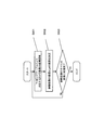
- FIG. 1 is a block diagram showing an overall configuration of a vehicle surrounding monitoring apparatus according to Embodiment 1 of the present invention.
- the photographing unit 1 has a plurality of (N) cameras 11 of a color or monochrome type having a solid-state imaging device such as a CCD or CMOS device as photographing means.
- the plurality of cameras 11 are all installed in a vehicle and used, for example, so that a wide range can be photographed with a high viewing angle lens such as a fisheye lens.
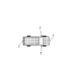
- FIG. 2 shows an example in which four cameras 11a to 11d are installed in the vehicle so that the entire periphery of the vehicle can be visually confirmed on the image.
- the cameras 11a and 11b are installed on a side mirror on the side of the vehicle
- the camera 11c is installed on the rear side of the vehicle
- the camera 11d is installed near a bumper on the front side of the vehicle.
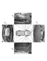
- Images actually taken by the cameras 11a to 11d are images as indicated by 301, 302, 303, and 304 in FIG.
- each camera is installed at the front, rear, left, and right positions of the vehicle. However, each camera can be placed at any position as long as the surroundings of the vehicle (not necessarily the entire circumference) can be appropriately captured. May be installed.
- the image processing unit 2 inputs captured images (hereinafter also referred to as “camera images”) from each camera 11, processes these captured images, and outputs the processed images to the display unit 3.
- the processing is an operation of creating a viewpoint conversion image and synthesizing an illustration image with an overhead image.
- the image processing unit 2 has an interface (not shown) connected to each camera 11 as an acquisition unit in order to acquire data indicating a camera image.
- the calculation in the image processing unit 2 includes a computer such as a CPU (Central Processing Unit) that executes a program for the calculation, and a storage device that stores information such as a table necessary for the calculation. It is realized by.
- the vehicle surrounding monitoring apparatus according to the present embodiment is mainly configured by the image processing unit 2.
- a display device such as a liquid crystal display or a plasma display is used.
- the display here may be shared with a vehicle-mounted GPS (Global Positioning System) terminal display (a display of a so-called car navigation system).
- GPS Global Positioning System
- the overhead image conversion unit 21 serving as a conversion unit performs signal processing for converting a camera image captured from the camera 11 into an image viewed from the designated virtual viewpoint with the ground as a projection plane.
- the bird's-eye view image is, for example, an image looking down perpendicularly to the ground from the virtual viewpoint position.
- the process of converting the camera image into a bird's-eye view image from the virtual viewpoint is performed with reference to the mapping table 23.
- the mapping table 23 defines a correspondence relationship between input (pixel coordinates of a camera image) and output (pixel coordinates of an overhead image) in advance, and will be described in detail later.
- FIG. 4 is an example in which the camera images 301, 302, 303, and 304 in FIG. 3 are converted into bird's-eye views 401, 402, 403, and 404 viewed from above the vehicle.
- the bird's-eye view image synthesizing unit 22 as a synthesizing unit generates a single output image by synthesizing the plurality of bird's-eye images generated by the bird's-eye view image conversion unit 21, and outputs the output image to the display unit 3.
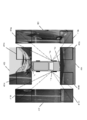
- FIG. 5 is an example of one output image (composite image) 405 generated from the overhead images 401, 402, 403, and 404 in FIG.
- overlapping areas 411a, 411c, 412a, 412d, 413b, 413c, 414b, and 414d are areas (overlapping areas) where two overhead images overlap.
- the region 411a of the overhead image 401 corresponding to the camera 11a on the vehicle side surface and the region 411c of the overhead image 403 corresponding to the camera 11c on the vehicle rear side overlap.
- the region 413c of the overhead image 403 corresponding to the camera 11c behind the vehicle and the region 413b of the overhead image 402 corresponding to the camera 11b on the side of the vehicle overlap.
- the region 414b of the overhead image 402 corresponding to the camera 11b on the vehicle side surface and the region 414d of the overhead image 404 corresponding to the camera 11d in front of the vehicle overlap.
- the overlapping area is synthesized by weighted addition of the overhead images. The weight applied to each overhead image is obtained by referring to a blend rate table 24 described later.
- the mapping table 23 is a table in which the relationship between the camera image and the overhead image is associated.
- the pixel coordinates of each camera image and the corresponding pixel coordinates of the overhead image are described as a pair.
- FIG. 6 is a diagram illustrating a method for acquiring pixel coordinates of a camera image with reference to a mapping table.
- the mapping table 501 is a table in which the coordinates of the overhead image 502 and the coordinates of the camera image 503 are associated one by one.
- a mapping table is created for each of a plurality of cameras.
- the mapping table is stored in, for example, a ROM or a RAM in order to perform a composite image generation process at high speed.
- the blend rate table 24 is a table showing how many pixels of which bird's-eye image are used when two output images are superimposed to synthesize one output image.
- FIG. 7 shows an example in which overlapping regions of two overhead images are synthesized. 7 is realized by calculating the luminance of each pixel according to equation (1).
- the composite image 621 is an image obtained by combining the overhead images 601 and 602.
- a weight table is used as a method for synthesizing overlapping regions using a blend rate table will be described.
- the weight applied to the bird's-eye view images 601 and 602 at the time of composition in the overlapping area is obtained by referring to the weight tables 611 and 612 having the same size as the overlapping area.
- FIG. 7 shows an example in which overlapping regions of two overhead images are synthesized. 7 is realized by calculating the luminance of each pixel according to equation (1).
- the composite image 621 is an image obtained by combining the overhead images 601 and 602.
- a weight table is used as
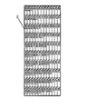
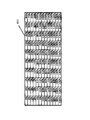
- the magnitudes of the weights for each pixel determined in the weight tables 611 and 612 are expressed by color shading (that is, larger weights are expressed by darker colors).
- 8A and 8B are examples in which the weight tables 611 and 612 in FIG. 7 are represented by numerical values. Each value in the weight table of FIGS. 8A and 8B corresponds to each pixel, and the weight is set within a range of 0% or more and 100% or less. Further, the relationship of Expression (2) is established with respect to the weight of each pixel.
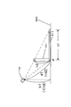
- FIGS. 9A, 9B, and 9C an example in which an overlapping region including the periphery of the three-dimensional object is combined is illustrated in FIGS. 9A, 9B, and 9C. Will be described with reference to FIG.
- the camera 11d in front of the vehicle is installed at a height h1 from the ground
- the camera 11b on the right side of the vehicle is installed at a height h2 (> h1) from the ground.
- the cameras 11b and 11d photograph a three-dimensional object 701 having a height h3 ( ⁇ h1) located at a point P in the vehicle surrounding area 900
- the three-dimensional object 701 extends in the respective projection directions in the camera image. Appear as projected solid objects 911 and 912 projected on the ground.
- the projected three-dimensional object 911 in the captured image of the camera 11d is larger than the projected three-dimensional object 912 in the captured image of the camera 11b.
- the pixels of the overhead image with a short distance from the camera are preferentially used. become. That is, in this conventional example, the weight is derived from the distance. For this reason, a problem may occur when the distances d1 and d2 between the cameras 11d and 11b and the point P are equal. Generally, the mounting positions of the cameras 11b and 11d are actually different, and the heights h1 and h2 are different even if the distances d1 and d2 are the same.
- the projection solid objects 711 and 712 generated from the solid object 701 located at the point P are different in size (elongation).
- the weights w1 and w2 are derived from the equal distances d1 and d2, and thus become equal.
- weighting that can reduce distortion in the projection direction of a three-dimensional object is performed in consideration of the camera attachment position, particularly the attachment height.
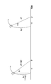
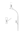
- the weight setting method in the present embodiment will be described with reference to FIG. In FIG. 10, the distance between the point P1 at which the perpendicular line drawn from the camera 11d located at the height h1 intersects the ground and the point P is t1, and the perpendicular line drawn from the camera 11b located at the height h2 in the ground direction.
- the distance between the point that intersects the ground and the point P is t2.
- the bird's-eye view image is an image projected on the ground in the present embodiment, and is preferably an image looking down directly from the virtual viewpoint as much as possible.
- the proposed weight setting method focuses on the angles ⁇ 1 and ⁇ 2 at which the cameras 11d and 11b look down at the point P, not the distances d1 and d2 from the cameras 11d and 11b to the point P. That is, since the overhead image corresponding to the camera whose angle looking down at the point P is relatively acute is relatively close to the image looking down directly below, the weight of such an overhead image is set high.
- the weighting reflecting this is expressed by the following formulas (5), (6), (7), and (8).
- the three-dimensional object distortion (elongation in the projection direction) at the point P has the same length, so that the weights w1 and w2 at the point P are equal.
- the weight w2 of the overhead view image corresponding to the camera 11b located at a more acute angle becomes larger. That is, in the synthesis of the pixel corresponding to the point P, the pixel of the overhead image corresponding to the camera 11b that is installed at a high position and has a small distortion of the three-dimensional object is preferentially used.
- the projected three-dimensional object 711 having a large distortion because it corresponds to the camera 11d at a relatively low position has an influence from the overhead image corresponding to the other camera 11b. As a result, it becomes inconspicuous in the composite image.
- the projection three-dimensional object 712 having a small distortion because it corresponds to the camera 11b at a relatively high position is not so strongly affected by the overhead image corresponding to the other camera 11d, and as a result, the projection three-dimensional object 711 in the composite image. Appears more conspicuous than.
- the weight setting method a case where the most focused height is set as a parameter according to how high the distortion of the three-dimensional object is focused will be described.
- the positions of the cameras 11d and 11b are represented by the heights h1 and h2 from the ground, and the distances between the point P and the point where the perpendicular line dropped from the cameras 11d and 11b to the ground intersects the ground are t1 and t2.
- the height H at which distortion is to be reduced is newly set as a parameter.
- the actual setting of the height H is about 50-80cm, although it depends on the camera mounting height. This height needs to be set lower than the actual camera mounting position. Further, the height H of interest is constant regardless of whether or not an object exists at the point P, and the weight is calculated. That is, the weight setting process in the present embodiment does not require object detection, and is performed uniformly based on a predetermined height H regardless of the presence or absence of an object. When there is no object, that is, when the ground is displayed in the overhead view image, the ground at the same position is captured in the overlapping region, and thus weighting assuming the height H of interest has an adverse effect on the composite image. Absent.
- FIG. 12 is a flowchart showing an operation example of the overhead image conversion unit 21 that generates an overhead image at a certain timing when the input of the camera image is confirmed.
- step S001 the mapping table 23 is referred to in order to obtain the coordinates of the camera image corresponding to the coordinates xt, yt of the overhead image. Since the mapping table 23 lists the coordinates of the camera image corresponding to the coordinates xt, yt of the overhead view image, the coordinates xi, yi of the corresponding camera image can be acquired.
- step S002 the pixel value at the coordinates xi, yi of the camera image is acquired, and this pixel value is used as the pixel value at the coordinates xt, yt of the overhead image.
- step S003 the process of steps S001 and S002 is repeatedly performed until all the pixel values of the overhead view pixels are acquired by determining whether or not all the pixels necessary for generating the overhead image are acquired.
- the overhead image conversion unit 21 repeats the process of FIG. 12 until all the overhead images at a certain timing are generated.
- FIG. 13 is a flowchart illustrating an operation example of the overhead image synthesis unit 22 that synthesizes these overhead images and generates an output image at a timing when a plurality of overhead images are generated.
- step S011 an overhead image having pixel values of coordinates xo and yo of the output image to be finally synthesized is selected.
- step S012 it is determined whether or not there are a plurality of bird's-eye view images that combine the pixels of the coordinates xo and yo of the output image. If there is one corresponding bird's-eye view image, the process proceeds to step S015. If there are two overhead images, it is determined as an overlapping region, and the process proceeds to step S013.
- step S013 the pixel values of the two overhead images corresponding to the coordinates xo and yo of the output image are acquired.
- step S014 a weight for synthesizing the pixel values of the overhead view image acquired in step S013 is acquired from the blend rate table 24.
- step S015 the pixels of the coordinates xo and yo of the output image are synthesized. If the corresponding pixels are present in the two overhead images, they are synthesized by equation (1) based on the weight obtained in step S014. If it exists in only one bird's-eye view image, the pixels of the coordinates xo and yo of that bird's-eye view image are used as they are.
- step S016 it is determined whether or not all the pixel values necessary for generating the output image have been acquired, and the processes from step S011 to step S015 are repeatedly performed until all the pixel values are acquired.
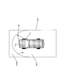
- This embodiment is different from the first embodiment in that a three-dimensional space model is used in the conversion process from a camera image to a bird's-eye view image, and this point will be mainly described.
- This three-dimensional space model is an omnidirectional curved surface model having a curved surface that rises in a complete bowl shape so as to surround all azimuths of the vehicle in a world coordinate system based on the vehicle.
- the area on the vehicle rear side is a plane projection area 1401 in which the projection surface forms a horizontal plane, while the area on the vehicle front side is projected.
- a curved surface projection area 1402 whose surface has a bowl shape is assumed.
- the vehicle surrounding area 1400 is divided by a boundary B into a plane projection area 1401 and a curved surface projection area 1402.
- the pixels of the camera image are mapped onto the horizontal projection plane 1501 of the front curved surface model 1500 if they are within the plane projection region 1401, and are mapped onto the bowl-shaped projection plane 1502 of the front curved surface model 1500 if they are within the curved projection region 1402.
- the front curved surface model 1500 includes only the horizontal projection surface 1501 at the rear of the vehicle, and includes the saddle-shaped projection surface 1502 that curves and rises from the horizontal projection surface 1501 at the front of the vehicle. Stipulated.
- the camera image is mapped to the front curved surface model 1500 as shown in FIG.
- the length L3 of the projected three-dimensional object 1600 on the front curved surface model 1500 as a result of the projection of the tip of the three-dimensional object 701 on the curved surface portion (the saddle-shaped projection surface 1502 in FIG. 15) It becomes shorter than the length L1 of the projection three-dimensional object 911 (FIG. 9B).
- the projected three-dimensional object (not shown) that appears in the overhead image generated from the mapping image in the present embodiment is replaced with the projected three-dimensional object that appears in the overhead image directly generated from the camera image in the first embodiment. It can be shorter than 711 (FIG. 9A).
- the present embodiment it is possible to further reduce the distortion of the three-dimensional object in the overhead view image in front of the vehicle.
- the three-dimensional object 1710 in front of the vehicle is elongated compared to the output image 1702 obtained through the simple planar projection. It is suppressed and distortion is reduced.
- the output image 1801 obtained through the front curved projection as in the present embodiment has a wider field of view in the vehicle rear region 1810 than the output image 1802 obtained through the simple planar projection. It can be seen that is secured.
- an output image is formed through a planar projection that allows the distance sense to be easily understood at the rear of the vehicle, and is output through a curved projection that facilitates confirmation of the surroundings at the front of the vehicle.
- An image is formed.
- the composite image is displayed when, for example, the vehicle is moved backward to put the vehicle in a parking lot. Therefore, at the rear of the vehicle, which is the traveling direction of the vehicle, it is more necessary to faithfully reproduce the positional relationship between the vehicle and an object located in the vicinity thereof than to ensure a wide field of view.
- the opposite is true in front of the vehicle or on the side of the vehicle that is not the direction of travel of the vehicle. In the present embodiment, these requirements can be satisfied simultaneously.
- the vehicle surrounding monitoring apparatus is useful as a vehicle surrounding monitoring apparatus or the like that is mounted on a vehicle and combines a plurality of captured images around the vehicle and provides the combined image to a driver or the like. It is.
Abstract
Description
p = p1 × w1+ p2 × w2 ・・・(1)
w1 + w2 = 1 ・・・(2)
図1は、本発明の実施の形態1に係る車両周囲監視装置の全体構成を示すブロック図である。撮影部1は、CCDまたはCMOSデバイス等の固体撮像素子を有するカラーまたはモノクロのタイプの複数(N個)のカメラ11を撮影手段として有する。これら複数のカメラ11はいずれも車両に設置して使用されるものであり、例えば魚眼レンズ等の高視野角のレンズにより広範囲を撮影できるよう構成されている。
w1 = d2 / (d1 + d2) ・・・(3)
w2 = d1 / (d1 + d2) ・・・(4)
w1 = θ2 / (θ1 + θ2) ・・・(5)
w2 = θ1 / (θ1 + θ2) ・・・(6)
θ1 = arctan( t1 / h1 ) ・・・(7)
θ2 = arctan( t2 / h2 ) ・・・(8)
θ1 = arctan( t1 / (h1 - H))・・・(9)
θ2 = arctan( t2 / (h2 - H))・・・(10)
以下、本発明の実施の形態2について説明する。本実施の形態における車両周囲監視装置の基本構成は実施の形態1と同様であるため、詳細な構成についての説明は省略する。
2 画像処理部
3 表示部
11、11a、11b、11c、11d カメラ
21 俯瞰画像変換部
22 俯瞰画像合成部
23、501 マッピングテーブル
24 ブレンド率テーブル
301、302、303、304、503 カメラ画像
401、402、403、404、502、601、602 俯瞰画像
405、621 合成画像
411a、411c 重複領域
412a、412d 重複領域
413b、413c 重複領域
414b、414d 重複領域
511、512 座標
611、612 重みテーブル
701 立体物
710 投影面
711、712、911、912、1600 投影立体物
900、1400 車両周囲領域
1401 平面投影領域
1402 曲面投影領域
1500 前方曲面モデル
1501 水平投影面
1502 椀状投影面
Claims (5)
- 車両周囲の領域を撮影する複数の撮影手段とともに用いる車両周囲監視装置であって、
前記複数の撮影手段により撮影された複数の画像を示すデータを取得する取得手段と、
取得されたデータに基づいて生成された複数の俯瞰画像を合成することにより、出力画像を得る合成手段と、を有し、
前記合成手段は、
異なる撮影手段に対応する異なる俯瞰画像の重複領域において、当該異なる俯瞰画像の画素を、当該画素に対応する地点を前記異なる撮影手段から見下ろす角度に応じて決定された比率に基づいて、合成する、
車両周囲監視装置。 - 前記角度は、前記異なる撮影手段から前記地点の地面上の位置を見下ろす角度である、
請求項1記載の車両周囲監視装置。 - 前記角度は、前記異なる撮影手段から前記地点の地面から所定の高さの位置を見下ろす角度である、
請求項1記載の車両周囲監視装置。 - 前記角度は、前記異なる撮影手段の車両への取り付け位置から地面に向けて延びる垂線と、前記異なる撮影手段の車両への取り付け位置から前記地点に向けて延びる直線とが成す角度である、
請求項1記載の車両周囲監視装置。 - 取得されたデータに基づいて複数の俯瞰画像を生成する変換手段をさらに有し、
前記変換手段は、
取得されたデータに示された複数の画像をそれぞれ3次元空間モデルにマッピングすることにより、複数の俯瞰画像を生成し、
前記3次元空間モデルは、車両後方では水平面のみを含み、且つ、車両前方では水平面から椀状に湾曲して立ち上がる曲面を含むように、定められる、
請求項1記載の車両周囲監視装置。
Priority Applications (3)
| Application Number | Priority Date | Filing Date | Title |
|---|---|---|---|
| US13/322,488 US20120069153A1 (en) | 2009-05-25 | 2010-05-20 | Device for monitoring area around vehicle |
| EP10780226.6A EP2437494B1 (en) | 2009-05-25 | 2010-05-20 | Device for monitoring area around vehicle |
| JP2011515870A JP5444338B2 (ja) | 2009-05-25 | 2010-05-20 | 車両周囲監視装置 |
Applications Claiming Priority (2)
| Application Number | Priority Date | Filing Date | Title |
|---|---|---|---|
| JP2009124877 | 2009-05-25 | ||
| JP2009-124877 | 2009-05-25 |
Publications (1)
| Publication Number | Publication Date |
|---|---|
| WO2010137265A1 true WO2010137265A1 (ja) | 2010-12-02 |
Family
ID=43222393
Family Applications (1)
| Application Number | Title | Priority Date | Filing Date |
|---|---|---|---|
| PCT/JP2010/003405 WO2010137265A1 (ja) | 2009-05-25 | 2010-05-20 | 車両周囲監視装置 |
Country Status (4)
| Country | Link |
|---|---|
| US (1) | US20120069153A1 (ja) |
| EP (1) | EP2437494B1 (ja) |
| JP (1) | JP5444338B2 (ja) |
| WO (1) | WO2010137265A1 (ja) |
Cited By (9)
| Publication number | Priority date | Publication date | Assignee | Title |
|---|---|---|---|---|
| WO2012169353A1 (ja) * | 2011-06-07 | 2012-12-13 | 株式会社小松製作所 | 作業車両の周辺監視装置 |
| WO2013053589A1 (de) * | 2011-10-14 | 2013-04-18 | Robert Bosch Gmbh | Verfahren zur darstellung eines fahrzeugumfeldes |
| CN103959341A (zh) * | 2011-12-07 | 2014-07-30 | 罗伯特·博世有限公司 | 用于呈现车辆环境的方法 |
| WO2014174884A1 (ja) * | 2013-04-24 | 2014-10-30 | 住友重機械工業株式会社 | 処理対象画像生成装置、処理対象画像生成方法、及び操作支援システム |
| WO2015133367A1 (ja) * | 2014-03-07 | 2015-09-11 | 日立建機株式会社 | 作業機械の周辺監視装置 |
| WO2017022497A1 (ja) * | 2015-08-04 | 2017-02-09 | 株式会社デンソー | 運転者に支援画像を提示する装置及びその方法 |
| WO2017077650A1 (ja) * | 2015-11-06 | 2017-05-11 | 三菱電機株式会社 | 画像処理装置、画像処理方法及び画像処理プログラム |
| JP2019185381A (ja) * | 2018-04-10 | 2019-10-24 | クラリオン株式会社 | 車両周囲画像生成装置 |
| JP2019191853A (ja) * | 2018-04-24 | 2019-10-31 | クラリオン株式会社 | 画像処理装置及び画像処理方法 |
Families Citing this family (33)
| Publication number | Priority date | Publication date | Assignee | Title |
|---|---|---|---|---|
| US9105128B2 (en) | 2011-08-26 | 2015-08-11 | Skybox Imaging, Inc. | Adaptive image acquisition and processing with image analysis feedback |
| US8873842B2 (en) | 2011-08-26 | 2014-10-28 | Skybox Imaging, Inc. | Using human intelligence tasks for precise image analysis |
| WO2013032823A1 (en) | 2011-08-26 | 2013-03-07 | Skybox Imaging, Inc. | Adaptive image acquisition and processing with image analysis feedback |
| EP2620917B1 (en) * | 2012-01-30 | 2019-08-28 | Harman Becker Automotive Systems GmbH | Viewing system and method for displaying an environment of a vehicle |
| EP2831621B1 (en) * | 2012-03-26 | 2016-07-13 | Robert Bosch GmbH | Multi-surface model-based tracking |
| JP5669791B2 (ja) * | 2012-08-07 | 2015-02-18 | 本田技研工業株式会社 | 移動体の周辺画像表示装置 |
| DE102012018325A1 (de) * | 2012-09-15 | 2014-03-20 | DSP-Weuffen GmbH | Verfahren und Vorrichtung für ein bildgebendes Fahrerassistenzsystem mit adaptiver Umsichtdarstellung |
| US9262868B2 (en) * | 2012-09-19 | 2016-02-16 | Google Inc. | Method for transforming mapping data associated with different view planes into an arbitrary view plane |
| JP6079131B2 (ja) * | 2012-10-25 | 2017-02-15 | 富士通株式会社 | 画像処理装置、方法、及びプログラム |
| JP6084434B2 (ja) * | 2012-10-31 | 2017-02-22 | クラリオン株式会社 | 画像処理システム及び画像処理方法 |
| US9674490B2 (en) * | 2013-04-18 | 2017-06-06 | Magna Electronics Inc. | Vision system for vehicle with adjustable cameras |
| TW201445440A (zh) * | 2013-05-30 | 2014-12-01 | Hon Hai Prec Ind Co Ltd | 集裝箱資料中心移動系統 |
| KR101573576B1 (ko) * | 2013-10-08 | 2015-12-01 | 현대자동차주식회사 | Avm 시스템의 이미지 처리 방법 |
| JP6330383B2 (ja) * | 2014-03-12 | 2018-05-30 | 株式会社デンソー | 合成画像生成装置、および合成画像生成プログラム |
| US10442355B2 (en) * | 2014-09-17 | 2019-10-15 | Intel Corporation | Object visualization in bowl-shaped imaging systems |
| US20160150189A1 (en) * | 2014-11-20 | 2016-05-26 | Caterpillar Inc. | Image processing system and method |
| DE102014225883A1 (de) * | 2014-12-15 | 2016-06-16 | Robert Bosch Gmbh | Kamerasystem und Verfahren zum Visualisieren mindestens eines Fahrzeugumfeldbereiches einesFahrzeugumfeldes eines Fahrzeuges |
| KR102270677B1 (ko) * | 2015-01-13 | 2021-06-29 | 현대모비스 주식회사 | 차량 안전 주행 장치 |
| DE102015205507B3 (de) * | 2015-03-26 | 2016-09-29 | Zf Friedrichshafen Ag | Rundsichtsystem für ein Fahrzeug |
| EP3086279A1 (en) * | 2015-04-24 | 2016-10-26 | KNORR-BREMSE Systeme für Nutzfahrzeuge GmbH | Image synthesizer for a driver assisting system |
| DE102015204214A1 (de) | 2015-05-07 | 2016-11-10 | Robert Bosch Gmbh | Verfahren zur Darstellung einer Fahrzeugumgebung eines Fahrzeuges |
| US9787951B2 (en) * | 2015-12-18 | 2017-10-10 | Serge Kannon | Vehicle proximity warning system |
| JP6868805B2 (ja) * | 2016-06-07 | 2021-05-12 | パナソニックIpマネジメント株式会社 | 画像生成装置、画像生成方法、およびプログラム |
| DE102016225073A1 (de) * | 2016-12-15 | 2018-06-21 | Conti Temic Microelectronic Gmbh | Vorrichtung zur bereitstellung einer verbesserten hinderniserkennung |
| DE102016124978A1 (de) | 2016-12-20 | 2018-06-21 | Connaught Electronics Ltd. | Virtuelle Repräsentation einer Umgebung eines Kraftfahrzeugs in einem Fahrerassistenzsystem mit mehreren Projektionsflächen |
| DE102016124989A1 (de) | 2016-12-20 | 2018-06-21 | Bayerische Motoren Werke Aktiengesellschaft | Bordsteinrepräsentation mit einem dreidimensionalen Körper in einem Fahrerassistenzsystem für ein Kraftfahrzeug |
| JP6962372B2 (ja) * | 2017-08-25 | 2021-11-05 | 株式会社ソシオネクスト | 補正装置、補正プログラム及び記録媒体 |
| FR3071333B1 (fr) * | 2017-09-15 | 2021-06-11 | Renault Sas | Procede d’affichage sur un ecran d’un environnement d’un vehicule automobile, et vehicule automobile dans lequel un tel procede est mis en œuvre |
| JP7115300B2 (ja) * | 2018-12-26 | 2022-08-09 | 株式会社デンソー | 画像生成装置及び画像表示システム |
| KR20210030523A (ko) * | 2019-09-09 | 2021-03-18 | 현대자동차주식회사 | 차량 및 그 제어 방법 |
| WO2021054797A1 (ko) * | 2019-09-19 | 2021-03-25 | 주식회사 윌러스표준기술연구소 | 스케일링 프로세스를 사용하는 비디오 신호 처리 방법 및 장치 |
| US11037328B1 (en) | 2019-12-31 | 2021-06-15 | Lyft, Inc. | Overhead view image generation |
| CN111968184B (zh) * | 2020-08-24 | 2024-04-02 | 北京茵沃汽车科技有限公司 | 一种在全景环视系统中实现视图随动的方法、装置及介质 |
Citations (4)
| Publication number | Priority date | Publication date | Assignee | Title |
|---|---|---|---|---|
| JP3286306B2 (ja) | 1998-07-31 | 2002-05-27 | 松下電器産業株式会社 | 画像生成装置、画像生成方法 |
| JP2005167309A (ja) | 2003-11-28 | 2005-06-23 | Nippon Soken Inc | 運転支援装置 |
| JP2007274377A (ja) | 2006-03-31 | 2007-10-18 | Denso Corp | 周辺監視装置、プログラム |
| JP2008048317A (ja) * | 2006-08-21 | 2008-02-28 | Sanyo Electric Co Ltd | 画像処理装置並びに視界支援装置及び方法 |
Family Cites Families (8)
| Publication number | Priority date | Publication date | Assignee | Title |
|---|---|---|---|---|
| KR20020033816A (ko) * | 2000-07-19 | 2002-05-07 | 마츠시타 덴끼 산교 가부시키가이샤 | 감시시스템 |
| DE10059313A1 (de) * | 2000-11-29 | 2002-06-13 | Bosch Gmbh Robert | Anordnung und Verfahren zur Überwachung des Umfelds eines Fahrzeugs |
| JP4766841B2 (ja) * | 2003-09-08 | 2011-09-07 | 株式会社オートネットワーク技術研究所 | 車両に搭載されるカメラ装置及び車両周辺監視装置 |
| JP2005333565A (ja) * | 2004-05-21 | 2005-12-02 | Auto Network Gijutsu Kenkyusho:Kk | 監視装置 |
| JP4780385B2 (ja) * | 2005-11-17 | 2011-09-28 | アイシン精機株式会社 | 周辺監視システム |
| JP4969269B2 (ja) * | 2007-02-21 | 2012-07-04 | アルパイン株式会社 | 画像処理装置 |
| JP5120880B2 (ja) * | 2007-10-15 | 2013-01-16 | アルパイン株式会社 | 画像処理装置及び画像処理方法 |
| JP5132249B2 (ja) * | 2007-10-23 | 2013-01-30 | アルパイン株式会社 | 車載用撮像装置 |
-
2010
- 2010-05-20 EP EP10780226.6A patent/EP2437494B1/en active Active
- 2010-05-20 JP JP2011515870A patent/JP5444338B2/ja active Active
- 2010-05-20 WO PCT/JP2010/003405 patent/WO2010137265A1/ja active Application Filing
- 2010-05-20 US US13/322,488 patent/US20120069153A1/en not_active Abandoned
Patent Citations (4)
| Publication number | Priority date | Publication date | Assignee | Title |
|---|---|---|---|---|
| JP3286306B2 (ja) | 1998-07-31 | 2002-05-27 | 松下電器産業株式会社 | 画像生成装置、画像生成方法 |
| JP2005167309A (ja) | 2003-11-28 | 2005-06-23 | Nippon Soken Inc | 運転支援装置 |
| JP2007274377A (ja) | 2006-03-31 | 2007-10-18 | Denso Corp | 周辺監視装置、プログラム |
| JP2008048317A (ja) * | 2006-08-21 | 2008-02-28 | Sanyo Electric Co Ltd | 画像処理装置並びに視界支援装置及び方法 |
Non-Patent Citations (1)
| Title |
|---|
| See also references of EP2437494A4 |
Cited By (23)
| Publication number | Priority date | Publication date | Assignee | Title |
|---|---|---|---|---|
| US8982212B2 (en) | 2011-06-07 | 2015-03-17 | Komatsu Ltd. | Surrounding area monitoring device for work vehicle |
| JP2012256960A (ja) * | 2011-06-07 | 2012-12-27 | Komatsu Ltd | 作業車両の周辺監視装置 |
| CN103155552A (zh) * | 2011-06-07 | 2013-06-12 | 株式会社小松制作所 | 作业车辆的周边监视装置 |
| WO2012169353A1 (ja) * | 2011-06-07 | 2012-12-13 | 株式会社小松製作所 | 作業車両の周辺監視装置 |
| WO2013053589A1 (de) * | 2011-10-14 | 2013-04-18 | Robert Bosch Gmbh | Verfahren zur darstellung eines fahrzeugumfeldes |
| CN103959341A (zh) * | 2011-12-07 | 2014-07-30 | 罗伯特·博世有限公司 | 用于呈现车辆环境的方法 |
| JP2014216797A (ja) * | 2013-04-24 | 2014-11-17 | 住友重機械工業株式会社 | 処理対象画像生成装置、処理対象画像生成方法、及び操作支援システム |
| WO2014174884A1 (ja) * | 2013-04-24 | 2014-10-30 | 住友重機械工業株式会社 | 処理対象画像生成装置、処理対象画像生成方法、及び操作支援システム |
| US10621743B2 (en) | 2013-04-24 | 2020-04-14 | Sumitomo Heavy Industries, Ltd. | Processing-target image creating device, processing-target image creating method, and operation assisting system |
| KR101752613B1 (ko) | 2014-03-07 | 2017-06-29 | 히다찌 겐끼 가부시키가이샤 | 작업 기계의 주변 감시 장치 |
| WO2015133367A1 (ja) * | 2014-03-07 | 2015-09-11 | 日立建機株式会社 | 作業機械の周辺監視装置 |
| JP2015171013A (ja) * | 2014-03-07 | 2015-09-28 | 日立建機株式会社 | 作業機械の周辺監視装置 |
| US10044933B2 (en) | 2014-03-07 | 2018-08-07 | Hitachi Construction Machinery Co., Ltd. | Periphery monitoring device for work machine |
| WO2017022497A1 (ja) * | 2015-08-04 | 2017-02-09 | 株式会社デンソー | 運転者に支援画像を提示する装置及びその方法 |
| JP2017033402A (ja) * | 2015-08-04 | 2017-02-09 | 株式会社デンソー | 車載表示制御装置、車載表示制御方法 |
| JP6239205B2 (ja) * | 2015-11-06 | 2017-11-29 | 三菱電機株式会社 | 画像処理装置、画像処理方法及び画像処理プログラム |
| JPWO2017077650A1 (ja) * | 2015-11-06 | 2017-12-07 | 三菱電機株式会社 | 画像処理装置、画像処理方法及び画像処理プログラム |
| GB2556797A (en) * | 2015-11-06 | 2018-06-06 | Mitsubishi Electric Corp | Image processing apparatus, image processing method, and image processing program |
| WO2017077650A1 (ja) * | 2015-11-06 | 2017-05-11 | 三菱電機株式会社 | 画像処理装置、画像処理方法及び画像処理プログラム |
| GB2556797B (en) * | 2015-11-06 | 2018-10-24 | Mitsubishi Electric Corp | Image processing apparatus, image processing method, and image processing program |
| JP2019185381A (ja) * | 2018-04-10 | 2019-10-24 | クラリオン株式会社 | 車両周囲画像生成装置 |
| JP2019191853A (ja) * | 2018-04-24 | 2019-10-31 | クラリオン株式会社 | 画像処理装置及び画像処理方法 |
| WO2019208278A1 (ja) * | 2018-04-24 | 2019-10-31 | クラリオン株式会社 | 画像処理装置及び画像処理方法 |
Also Published As
| Publication number | Publication date |
|---|---|
| EP2437494A4 (en) | 2016-09-28 |
| EP2437494A1 (en) | 2012-04-04 |
| JPWO2010137265A1 (ja) | 2012-11-12 |
| JP5444338B2 (ja) | 2014-03-19 |
| US20120069153A1 (en) | 2012-03-22 |
| EP2437494B1 (en) | 2017-10-11 |
Similar Documents
| Publication | Publication Date | Title |
|---|---|---|
| JP5444338B2 (ja) | 車両周囲監視装置 | |
| JP6310652B2 (ja) | 映像表示システム、映像合成装置及び映像合成方法 | |
| EP3160138B1 (en) | Image synthesis system, image synthesis device therefor, and image synthesis method | |
| JP4879031B2 (ja) | 運転支援システム、画像処理装置及びずれ検出方法 | |
| WO2013047012A1 (ja) | 車両周辺監視装置 | |
| WO2019192359A1 (zh) | 一种车载全景视频显示系统、方法及车载控制器 | |
| JP3652678B2 (ja) | 車両周囲監視装置およびその調整方法 | |
| JP4248570B2 (ja) | 画像処理装置並びに視界支援装置及び方法 | |
| WO2009116327A1 (ja) | 画像処理装置及び方法、運転支援システム、車両 | |
| JP4315968B2 (ja) | 画像処理装置並びに視界支援装置及び方法 | |
| JP2006287892A (ja) | 運転支援システム | |
| JP5003395B2 (ja) | 車両周辺画像処理装置及び車両周辺状況提示方法 | |
| JP5516998B2 (ja) | 画像生成装置 | |
| JP2009239754A (ja) | 画像処理装置、画像処理プログラム、画像処理システム及び画像処理方法 | |
| JP2013207637A (ja) | 画像処理装置及び方法、並びにコンピュータプログラム | |
| WO2017043331A1 (ja) | 画像処理装置、及び、画像処理方法 | |
| KR101278654B1 (ko) | 차량의 주변 영상 디스플레이 장치 및 방법 | |
| JP5271186B2 (ja) | 車両用画像表示装置 | |
| JP2013137698A (ja) | 俯瞰画像提示装置 | |
| JP2008034964A (ja) | 画像表示装置 | |
| JP2003346189A (ja) | 車両用映像表示装置 | |
| JP5305750B2 (ja) | 車両周辺表示装置およびその表示方法 | |
| JP2008294616A (ja) | 運転支援システム及び車両 | |
| WO2023095340A1 (ja) | 画像処理方法、画像表示方法、画像処理装置、及び画像表示装置 | |
| JP6007773B2 (ja) | 画像データ変換装置並びにナビゲーションシステムおよびカメラ装置並びに車両 |
Legal Events
| Date | Code | Title | Description |
|---|---|---|---|
| 121 | Ep: the epo has been informed by wipo that ep was designated in this application |
Ref document number: 10780226 Country of ref document: EP Kind code of ref document: A1 |
|
| WWE | Wipo information: entry into national phase |
Ref document number: 2011515870 Country of ref document: JP |
|
| NENP | Non-entry into the national phase |
Ref country code: DE |
|
| REEP | Request for entry into the european phase |
Ref document number: 2010780226 Country of ref document: EP |
|
| WWE | Wipo information: entry into national phase |
Ref document number: 13322488 Country of ref document: US Ref document number: 2010780226 Country of ref document: EP |