WO2010131358A1 - Coシフト触媒及びその製造方法、並びにcoシフト触媒を用いたcoシフト反応装置 - Google Patents
Coシフト触媒及びその製造方法、並びにcoシフト触媒を用いたcoシフト反応装置 Download PDFInfo
- Publication number
- WO2010131358A1 WO2010131358A1 PCT/JP2009/059068 JP2009059068W WO2010131358A1 WO 2010131358 A1 WO2010131358 A1 WO 2010131358A1 JP 2009059068 W JP2009059068 W JP 2009059068W WO 2010131358 A1 WO2010131358 A1 WO 2010131358A1
- Authority
- WO
- WIPO (PCT)
- Prior art keywords
- shift
- catalyst
- gas
- shift catalyst
- gasification
- Prior art date
- Legal status (The legal status is an assumption and is not a legal conclusion. Google has not performed a legal analysis and makes no representation as to the accuracy of the status listed.)
- Ceased
Links
Images


Classifications
-
- B—PERFORMING OPERATIONS; TRANSPORTING
- B01—PHYSICAL OR CHEMICAL PROCESSES OR APPARATUS IN GENERAL
- B01J—CHEMICAL OR PHYSICAL PROCESSES, e.g. CATALYSIS OR COLLOID CHEMISTRY; THEIR RELEVANT APPARATUS
- B01J23/00—Catalysts comprising metals or metal oxides or hydroxides, not provided for in group B01J21/00
- B01J23/38—Catalysts comprising metals or metal oxides or hydroxides, not provided for in group B01J21/00 of noble metals
- B01J23/40—Catalysts comprising metals or metal oxides or hydroxides, not provided for in group B01J21/00 of noble metals of the platinum group metals
- B01J23/42—Platinum
-
- B—PERFORMING OPERATIONS; TRANSPORTING
- B01—PHYSICAL OR CHEMICAL PROCESSES OR APPARATUS IN GENERAL
- B01J—CHEMICAL OR PHYSICAL PROCESSES, e.g. CATALYSIS OR COLLOID CHEMISTRY; THEIR RELEVANT APPARATUS
- B01J23/00—Catalysts comprising metals or metal oxides or hydroxides, not provided for in group B01J21/00
- B01J23/38—Catalysts comprising metals or metal oxides or hydroxides, not provided for in group B01J21/00 of noble metals
- B01J23/40—Catalysts comprising metals or metal oxides or hydroxides, not provided for in group B01J21/00 of noble metals of the platinum group metals
- B01J23/46—Ruthenium, rhodium, osmium or iridium
-
- B—PERFORMING OPERATIONS; TRANSPORTING
- B01—PHYSICAL OR CHEMICAL PROCESSES OR APPARATUS IN GENERAL
- B01J—CHEMICAL OR PHYSICAL PROCESSES, e.g. CATALYSIS OR COLLOID CHEMISTRY; THEIR RELEVANT APPARATUS
- B01J23/00—Catalysts comprising metals or metal oxides or hydroxides, not provided for in group B01J21/00
- B01J23/38—Catalysts comprising metals or metal oxides or hydroxides, not provided for in group B01J21/00 of noble metals
- B01J23/40—Catalysts comprising metals or metal oxides or hydroxides, not provided for in group B01J21/00 of noble metals of the platinum group metals
- B01J23/46—Ruthenium, rhodium, osmium or iridium
- B01J23/462—Ruthenium
-
- B—PERFORMING OPERATIONS; TRANSPORTING
- B01—PHYSICAL OR CHEMICAL PROCESSES OR APPARATUS IN GENERAL
- B01J—CHEMICAL OR PHYSICAL PROCESSES, e.g. CATALYSIS OR COLLOID CHEMISTRY; THEIR RELEVANT APPARATUS
- B01J23/00—Catalysts comprising metals or metal oxides or hydroxides, not provided for in group B01J21/00
- B01J23/38—Catalysts comprising metals or metal oxides or hydroxides, not provided for in group B01J21/00 of noble metals
- B01J23/40—Catalysts comprising metals or metal oxides or hydroxides, not provided for in group B01J21/00 of noble metals of the platinum group metals
- B01J23/46—Ruthenium, rhodium, osmium or iridium
- B01J23/468—Iridium
-
- B—PERFORMING OPERATIONS; TRANSPORTING
- B01—PHYSICAL OR CHEMICAL PROCESSES OR APPARATUS IN GENERAL
- B01J—CHEMICAL OR PHYSICAL PROCESSES, e.g. CATALYSIS OR COLLOID CHEMISTRY; THEIR RELEVANT APPARATUS
- B01J23/00—Catalysts comprising metals or metal oxides or hydroxides, not provided for in group B01J21/00
- B01J23/38—Catalysts comprising metals or metal oxides or hydroxides, not provided for in group B01J21/00 of noble metals
- B01J23/54—Catalysts comprising metals or metal oxides or hydroxides, not provided for in group B01J21/00 of noble metals combined with metals, oxides or hydroxides provided for in groups B01J23/02 - B01J23/36
- B01J23/56—Platinum group metals
- B01J23/63—Platinum group metals with rare earths or actinides
-
- B—PERFORMING OPERATIONS; TRANSPORTING
- B01—PHYSICAL OR CHEMICAL PROCESSES OR APPARATUS IN GENERAL
- B01J—CHEMICAL OR PHYSICAL PROCESSES, e.g. CATALYSIS OR COLLOID CHEMISTRY; THEIR RELEVANT APPARATUS
- B01J35/00—Catalysts, in general, characterised by their form or physical properties
- B01J35/60—Catalysts, in general, characterised by their form or physical properties characterised by their surface properties or porosity
- B01J35/61—Surface area
- B01J35/613—10-100 m2/g
-
- B—PERFORMING OPERATIONS; TRANSPORTING
- B01—PHYSICAL OR CHEMICAL PROCESSES OR APPARATUS IN GENERAL
- B01J—CHEMICAL OR PHYSICAL PROCESSES, e.g. CATALYSIS OR COLLOID CHEMISTRY; THEIR RELEVANT APPARATUS
- B01J35/00—Catalysts, in general, characterised by their form or physical properties
- B01J35/60—Catalysts, in general, characterised by their form or physical properties characterised by their surface properties or porosity
- B01J35/61—Surface area
- B01J35/615—100-500 m2/g
-
- C—CHEMISTRY; METALLURGY
- C01—INORGANIC CHEMISTRY
- C01B—NON-METALLIC ELEMENTS; COMPOUNDS THEREOF; METALLOIDS OR COMPOUNDS THEREOF NOT COVERED BY SUBCLASS C01C
- C01B3/00—Hydrogen; Gaseous mixtures containing hydrogen; Separation of hydrogen from mixtures containing it; Purification of hydrogen; Reversible storage of hydrogen
- C01B3/02—Production of hydrogen; Production of gaseous mixtures containing hydrogen
- C01B3/06—Production of hydrogen; Production of gaseous mixtures containing hydrogen by reaction of inorganic compounds containing electro-positively bound hydrogen with inorganic reducing agents
- C01B3/12—Production of hydrogen; Production of gaseous mixtures containing hydrogen by reaction of inorganic compounds containing electro-positively bound hydrogen with inorganic reducing agents by reaction of water vapour with carbon monoxide
- C01B3/16—Production of hydrogen; Production of gaseous mixtures containing hydrogen by reaction of inorganic compounds containing electro-positively bound hydrogen with inorganic reducing agents by reaction of water vapour with carbon monoxide using catalysts
-
- C—CHEMISTRY; METALLURGY
- C10—PETROLEUM, GAS OR COKE INDUSTRIES; TECHNICAL GASES CONTAINING CARBON MONOXIDE; FUELS; LUBRICANTS; PEAT
- C10K—PURIFYING OR MODIFYING THE CHEMICAL COMPOSITION OF COMBUSTIBLE GASES CONTAINING CARBON MONOXIDE
- C10K1/00—Purifying combustible gases containing carbon monoxide
- C10K1/02—Dust removal
- C10K1/024—Dust removal by filtration
-
- C—CHEMISTRY; METALLURGY
- C10—PETROLEUM, GAS OR COKE INDUSTRIES; TECHNICAL GASES CONTAINING CARBON MONOXIDE; FUELS; LUBRICANTS; PEAT
- C10K—PURIFYING OR MODIFYING THE CHEMICAL COMPOSITION OF COMBUSTIBLE GASES CONTAINING CARBON MONOXIDE
- C10K1/00—Purifying combustible gases containing carbon monoxide
- C10K1/08—Purifying combustible gases containing carbon monoxide by washing with liquids; Reviving the used wash liquors
-
- C—CHEMISTRY; METALLURGY
- C10—PETROLEUM, GAS OR COKE INDUSTRIES; TECHNICAL GASES CONTAINING CARBON MONOXIDE; FUELS; LUBRICANTS; PEAT
- C10K—PURIFYING OR MODIFYING THE CHEMICAL COMPOSITION OF COMBUSTIBLE GASES CONTAINING CARBON MONOXIDE
- C10K3/00—Modifying the chemical composition of combustible gases containing carbon monoxide to produce an improved fuel, e.g. one of different calorific value, which may be free from carbon monoxide
- C10K3/02—Modifying the chemical composition of combustible gases containing carbon monoxide to produce an improved fuel, e.g. one of different calorific value, which may be free from carbon monoxide by catalytic treatment
- C10K3/04—Modifying the chemical composition of combustible gases containing carbon monoxide to produce an improved fuel, e.g. one of different calorific value, which may be free from carbon monoxide by catalytic treatment reducing the carbon monoxide content, e.g. water-gas shift [WGS]
-
- B—PERFORMING OPERATIONS; TRANSPORTING
- B01—PHYSICAL OR CHEMICAL PROCESSES OR APPARATUS IN GENERAL
- B01J—CHEMICAL OR PHYSICAL PROCESSES, e.g. CATALYSIS OR COLLOID CHEMISTRY; THEIR RELEVANT APPARATUS
- B01J21/00—Catalysts comprising the elements, oxides, or hydroxides of magnesium, boron, aluminium, carbon, silicon, titanium, zirconium, or hafnium
- B01J21/02—Boron or aluminium; Oxides or hydroxides thereof
- B01J21/04—Alumina
-
- B—PERFORMING OPERATIONS; TRANSPORTING
- B01—PHYSICAL OR CHEMICAL PROCESSES OR APPARATUS IN GENERAL
- B01J—CHEMICAL OR PHYSICAL PROCESSES, e.g. CATALYSIS OR COLLOID CHEMISTRY; THEIR RELEVANT APPARATUS
- B01J21/00—Catalysts comprising the elements, oxides, or hydroxides of magnesium, boron, aluminium, carbon, silicon, titanium, zirconium, or hafnium
- B01J21/06—Silicon, titanium, zirconium or hafnium; Oxides or hydroxides thereof
- B01J21/063—Titanium; Oxides or hydroxides thereof
-
- B—PERFORMING OPERATIONS; TRANSPORTING
- B01—PHYSICAL OR CHEMICAL PROCESSES OR APPARATUS IN GENERAL
- B01J—CHEMICAL OR PHYSICAL PROCESSES, e.g. CATALYSIS OR COLLOID CHEMISTRY; THEIR RELEVANT APPARATUS
- B01J21/00—Catalysts comprising the elements, oxides, or hydroxides of magnesium, boron, aluminium, carbon, silicon, titanium, zirconium, or hafnium
- B01J21/06—Silicon, titanium, zirconium or hafnium; Oxides or hydroxides thereof
- B01J21/066—Zirconium or hafnium; Oxides or hydroxides thereof
-
- Y—GENERAL TAGGING OF NEW TECHNOLOGICAL DEVELOPMENTS; GENERAL TAGGING OF CROSS-SECTIONAL TECHNOLOGIES SPANNING OVER SEVERAL SECTIONS OF THE IPC; TECHNICAL SUBJECTS COVERED BY FORMER USPC CROSS-REFERENCE ART COLLECTIONS [XRACs] AND DIGESTS
- Y02—TECHNOLOGIES OR APPLICATIONS FOR MITIGATION OR ADAPTATION AGAINST CLIMATE CHANGE
- Y02P—CLIMATE CHANGE MITIGATION TECHNOLOGIES IN THE PRODUCTION OR PROCESSING OF GOODS
- Y02P20/00—Technologies relating to chemical industry
- Y02P20/50—Improvements relating to the production of bulk chemicals
- Y02P20/52—Improvements relating to the production of bulk chemicals using catalysts, e.g. selective catalysts
Definitions
- the present invention relates to a CO shift catalyst that converts CO in a gasification gas to CO 2 , a CO shift reaction apparatus using the same, and a purification method for the gasification gas.
- FIG. 2 is an explanatory diagram showing a coal gasification power plant according to the prior art.
- coal 101 is gasified in a gasification furnace 102 to obtain a gasification gas 103 as a product gas, and then dust is removed by a dust removing device 104.
- a dust removing device 104 Is converted to H 2 S, and then a CO shift reaction is caused by the CO shift reaction device 106, and then CO 2 is recovered by the H 2 S / CO 2 recovery device 107, and H 2 S in the gas is removed. I'm doing it.
- reference numeral 120 denotes air
- 121 denotes an air separator
- 122 denotes a gasified air compressor
- 123 denotes gasified air
- 124 denotes water vapor
- 125 denotes an H 2 S / CO 2 treatment system.
- the produced gas 108 after being processed by the H 2 S / CO 2 recovery device 107 is supplied to a combustor 111 of a gas turbine 110 which is a power generation means, where it is burned to produce a high temperature / high pressure combustion gas.
- the turbine 112 is driven by this combustion gas.
- the turbine 112 is connected to a generator 113, and the generator 113 generates electric power when the turbine 112 is driven.
- the exhaust gas 114 after driving the turbine 112 still has a temperature of 500 to 600 ° C., it is preferably sent to an HRSG (Heat Recovery Steam Generator) 115 to recover the thermal energy.
- HRSG Heat Recovery Steam Generator
- steam is generated by the thermal energy of the exhaust gas, and the steam turbine 116 is driven by the steam.
- the exhaust gas whose thermal energy has been recovered by the HRSG 115 is discharged into the atmosphere via the chimney 117 after the NOx content in the exhaust gas is removed by a denitration device (not shown).
- the gasification gas 103 gasified in the gasification furnace 101 requires a so-called CO shift reaction device 106 that converts CO contained in the gasification gas into CO 2 before separating the CO 2.
- CO shift reaction useful components CO 2 and H 2 are obtained by the reaction of the following formula (1).
- Various CO shift catalysts have been proposed as catalysts for promoting the CO shift reaction. For example, molybdenum (Mo) -cobalt (Co) catalyst supported on an aluminum oxide support, copper (Cu) -zinc (Zn). ) Based catalyst.
- the CO shift reaction device 106 in order to convert CO contained in a large amount in the gasification gas 103 into H 2 , in addition to the gas for the turbine, a gas composition suitable for synthesis of chemical products such as methanol and ammonia, for example. Of purified gas is obtained.
- Cu—Zn-based catalysts have a low reaction temperature of about 300 ° C. or less, and the energy efficiency of the gas purification system is good, but they are poisoned in the sulfur component (S component) atmosphere, so as shown in FIG. Like the coal gasification power plant 100-1, there is a problem that it cannot be used when the gas is not purified.
- a coal gasification power plant 100-2 for a Cu—Zn-based catalyst has a CO shift reaction device 106 installed on the downstream side of the H 2 S / CO 2 recovery device 107, The gas purification treatment of the gasification gas is performed by performing the CO shift reaction after the gas purification.
- the coal gasification power plant 100-2 in FIG. 3 it is necessary to raise the gas refined by the H 2 S / CO 2 recovery device 107 to around 300 ° C., which is a high temperature. There is a problem that it is disadvantageous.
- the present invention provides a CO shift catalyst having a high system energy efficiency and having a low-temperature activity and a sulfur-resistant atmosphere, a method for producing the same, a CO shift reaction apparatus using the CO shift catalyst, and a gasification gas It is an object to provide a purification method.
- a first invention of the present invention for solving the above-described problem is a CO shift catalyst for reforming carbon monoxide (CO) in a gas, and includes platinum (Pt), ruthenium (Ru), iridium (Ir ), Rhodium (Rh) or a mixture thereof as an active ingredient, and any one of titanium (Ti), aluminum (Al), zirconium (Zr) and cerium (Ce) carrying this active ingredient Is a CO shift catalyst characterized in that is used as a carrier.
- the second invention is the CO shift catalyst according to the first invention, wherein the carrier contains a complex oxide containing at least two kinds of elements.
- the third invention is the CO shift catalyst according to the first or second invention, wherein the addition amount of the active ingredient is 0.01 to 5% by weight.
- a fourth invention is a CO shift catalyst according to any one of the first to third inventions, characterized in that a sulfate radical remains.
- sulfuric acid is added to any oxide of titanium (Ti), aluminum (Al), zirconium (Zr), and cerium (Ce), or to a composite oxide containing at least two of these elements. And then evaporating water, heating at 500 to 600 ° C. in a heating furnace to leave a sulfate radical on the carrier, and then supporting the active ingredient on the carrier on which the sulfate radical remains. It exists in the manufacturing method of a CO shift catalyst.
- a sixth invention is characterized in that, in the fifth invention, the active ingredient is any one of platinum (Pt), ruthenium (Ru), iridium (Ir) and rhodium (Rh) or a mixture thereof. It exists in the manufacturing method of a CO shift catalyst.
- a seventh aspect of the invention is a CO shift reaction apparatus characterized in that any one of the first to fourth CO shift catalysts is packed in a reaction tower.
- a CO shift reaction is performed using any one of the first to fourth CO shift catalysts. Thereafter, the gasification gas after the CO shift reaction is further purified by a wet scrubber device, and then the carbonized gas in the gasification gas is removed.
- a CO shift reaction can be performed at a low temperature, and energy saving can be improved.
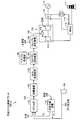
- FIG. 1 is a schematic view of a gasification gas purification system provided with a CO shift reaction apparatus filled with a CO shift catalyst according to the present embodiment.
- FIG. 2 is a schematic view of a gasification gas purification system provided with a CO shift reaction apparatus filled with a CO shift catalyst according to the prior art.
- FIG. 3 is a schematic view of a gasification gas purification system equipped with a CO shift reaction apparatus filled with another CO shift catalyst according to the prior art.
- FIG. 1 is a schematic view of a gasification gas purification system equipped with a CO shift reaction apparatus filled with a CO shift catalyst. As shown in FIG. 1
- a gasification gas purification system 10 includes a gasification furnace 11 that gasifies coal that is fuel F, a filter 13 that removes soot and dust in the gasification gas 12 that is a product gas, and a gasification A CO shift reaction device 15 having a CO shift catalyst 14 for converting CO in the gas 12 to CO 2 , a wet scrubber device 16 for removing halogen in the gasification gas 12 after the CO shift reaction, and a gasification gas 12 A first heat exchanger 17 that lowers the temperature of the gas, and a gas purification device 18 that includes an absorption tower 18A that absorbs CO 2 in the gasified gas 12 after the heat exchange, and a regeneration tower 18B that regenerates.
- reference numeral 20 denotes a regenerative superheater
- 21 denotes a second heat exchanger for heating the purified gas 19
- 22 denotes water vapor.
- the CO shift catalyst according to the present invention is a CO shift catalyst for reforming carbon monoxide (CO) in a gas, and any one of platinum (Pt), ruthenium (Ru), iridium (Ir), and rhodium (Rh).
- Pt platinum
- Ru ruthenium
- Ir iridium
- Rh rhodium
- One or a mixture thereof is used as an active ingredient, and any one of titanium (Ti), aluminum (Al), zirconium (Zr) and cerium (Ce) carrying the active ingredient is used as a carrier.
- a catalyst having excellent low-temperature activity can be provided and the amount of water vapor is reduced (for example, The CO shift reaction is allowed to proceed efficiently even in the case of causing the CO shift reaction to drop significantly from 350 ° C. to 250 ° C. This is because, as shown in a test example to be described later, by supporting a trace amount of metal such as Pt, good catalytic activity can be caused even in a low temperature activity and an S atmosphere.
- the carrier is preferably an oxide of TiO 2 , Al 2 O 3 , ZrO 2 , or CeO 2 .
- the carrier may contain a complex oxide in which at least two kinds or two or more kinds of elements are present.
- a complex oxide in which at least two kinds or two or more kinds of elements are present.
- the case where the composite oxide and the mixture coexist is also included.
- the composite oxide obtained, for example, TiO 2 -ZrO 2, TiO 2 -Al 2 O 3, TiO 2 -CeO 2, CeO 2 -ZrO 2, composite oxides such as ZrO 2 -Al 2 O 3 Can be illustrated.
- the addition amount of the active ingredient of any one of platinum (Pt), ruthenium (Ru), iridium (Ir), and rhodium (Rh) or a mixture thereof is preferably 0.01 to 5% by weight.
- the content is preferably 0.01 to 0.5% by weight.
- the catalyst according to the present invention is subjected to a sulfuric acid treatment in order to have sulfur resistance.
- a sulfuric acid treatment for example, the catalyst is immersed in a sulfuric acid-based aqueous solution such as sulfuric acid or thiosulfuric acid, and after drying, it is dried in a heating furnace in a high-temperature (about 500 to 600 ° C.) atmosphere to leave sulfate radicals in the catalyst. This is a processing method.
- sulfate radicals or sulfate radical precursors are sulfuric acid (H 2 SO 4 ), ammonium sulfate [(NH 4 ) 2 SO 4 ], ammonium sulfite [(NH 4 ) 2 SO 3 ], ammonium hydrogen sulfate [( NH 4 ) HSO 4 ], sulfuryl chloride (SO 2 Cl 2 ) and the like. Particularly preferred are sulfuric acid, ammonium sulfate and sulfuryl chloride.
- a dried Group III (and / or Group IV metal) hydroxide or oxide is added in an amount of 0.01 to 10 moles of 1 to 10 parts by weight thereof.
- An example is a method in which the treatment is preferably performed by dipping or flowing in a sulfate group-containing aqueous solution having a concentration of 0.1 to 5 molar.
- the CO shift reaction device 15 having the CO shift catalyst 14 is used to cause a CO shift reaction at a low temperature with a reduced steam supply amount, and then the gas after the CO shift reaction is further performed by the wet scrubber device 16.
- Purified gas 19 can be obtained by purifying the gasified gas and then removing carbon dioxide in the gasified gas.
- the gasification gas 12 is at a high temperature of 350 ° C., but the CO shift reaction is caused by the CO shift reaction device 15 at that temperature, so that the gas temperature is 300 ° C. or less (more preferably around 250 ° C.).
- the CO shift reaction can be performed at a lower temperature.
- the wet scrubber device 16 the gas temperature is lowered and the halides in the gas are removed, and then the gas purification device 18 performs gas purification. Therefore, the temperature is once lowered in the scrubber device as in the prior art.
- the CO shift reaction device 106 does not cause a CO shift reaction again at a high temperature, and a system configuration with improved energy efficiency can be constructed.
- the CO shift catalyst according to the present invention when gasification is performed in a coal gasification furnace, it is possible to perform a shift reaction in which the amount of water vapor is reduced to save energy, and the heat efficiency is good and the efficiency is high.
- a gas purification process can be provided.
- the obtained catalyst powder 1-1 was fixed with a 30-ton pressure molding machine, then crushed so that the particle size was in the range of 2 to 4 mm, and sieved to 100 ml of 1 mol% sulfuric acid aqueous solution. After being immersed and evaporated to dryness, the catalyst 1-1 (catalyst component: Pt; carrier component: TiO 2 ) subjected to sulfuric acid treatment by baking at 600 ° C. for 3 hours was obtained.
- Powder catalysts 1-2 to 1-4 were obtained in the same manner as in Test Example 1 except that the amount of Pt supported in Test Example 1 was changed to 0.01 wt%, 0.1 wt% and 5 wt%.
- the obtained catalyst powders 1-2 to 1-4 were fixed with a 30-ton pressure molding machine, and then crushed so as to have a particle size in the range of 2 to 4 mm. It was immersed in 100 ml of sulfuric acid aqueous solution, evaporated to dryness, and calcined at 600 ° C. for 3 hours to obtain sulfuric acid-treated catalyst 1-2 to 1-4 (catalyst component: Pt; support component: TiO 2 ). .
- Catalyst powders 2 to 10 were obtained in the same manner as in Test Example 1 except that the compositions and raw materials in Test Examples were changed to those described in Table 1.
- the obtained catalyst powders 2 to 10 were fixed with a 30-ton pressure molding machine, and then crushed so that the particle size would be in the range of 2 to 4 mm, followed by sieving to make 100 ml of 1 mol% sulfuric acid aqueous solution.
- catalyst 2 (catalyst component: Pt; support component: CeO 2 )
- catalyst 3 catalyst component: Pt; support component: ZrO) subjected to sulfuric acid treatment by calcination at 600 ° C.
- catalyst 4 catalyst component: Pt; support component: Al 2 O 3
- catalyst 5 catalyst component: Ru; support component: ZrO 2 / Al 2 O 3
- catalyst 6 catalyst component: Ru; support component) : CeO 2
- catalyst 7 catalyst component: Ir; support component: Al 2 O 3
- catalyst 8 catalyst component: Pt; support component: ZrO 2 / TiO 2
- catalyst 9 catalyst component: Ru; support component) : ZrO 2
- catalyst 10 catalyst component: Ru; support component: ZrO 2 Obtained.
- Comparative Example 1 A catalyst having the composition of the catalyst powder 3 of Test Example 3 and not subjected to sulfuric acid treatment after crushing and sieving was used as Comparative Catalyst 1.
- Comparative Example 2 Put 83.3 g of Hayashi Pure Chemical's Al 2 O 3 into a porcelain dish and dissolve the cobalt nitrate hexahydrate and ammonium molybdate tetrahydrate in 100 ml of water. After adding so that CoO was supported at 4 wt% and MoO 3 was supported at 13 wt%, it was impregnated by evaporation to dryness on a porcelain dish. The obtained powder was completely dried in a drier and then calcined at 500 ° C. for 3 hours (temperature increase rate: 100 ° C./h) to obtain comparative powder catalyst 2. The obtained comparative catalyst powder 2 was fixed with a 30-ton pressure molding machine, and then crushed so as to have a particle size in the range of 2 to 4 mm.
- the solution C was dripped uniformly over the said precipitation product liquid D over 30 minutes, and the precipitation product liquid F containing aluminum, zinc, and copper was obtained.
- the precipitation product F was aged by stirring for 2 hours, and then sufficiently washed so that the filtrate of the precipitation product F and Na ions and NO ions were not detected.
- the catalyst was dried at 100 ° C. for 24 hours, and then calcined at 300 ° C. for 3 hours to obtain a comparative catalyst powder.
- This comparative catalyst powder was designated as comparative catalyst powder 3.
- the obtained comparative catalyst powder 2 was fixed with a 30-ton pressure molding machine, and then crushed so that the particle size was in the range of 2 to 4 mm. .
- CO conversion rate (%) (1 ⁇ (catalyst layer outlet CO gas flow rate (mol / h) / catalyst layer inlet CO gas flow rate (mol / h)) In the hydrogen chloride exposure test, the CO conversion after 150 hours at an HCl concentration of 100 ppm was determined.
- the catalyst according to this test example has good activity even at a low temperature (200 ° C.), and each of the catalysts 1-1 and 8 has a CO conversion rate even after HCl exposure. It was good.
- the comparative catalyst 1 according to the comparative example was not subjected to sulfuric acid treatment, the CO conversion rate was significantly reduced or deactivated at a low temperature (200 ° C.).
- Comparative Catalysts 2 and 3 were less active at low temperatures.
- the catalyst according to this test example was good because the specific surface area was increased compared to the comparative catalyst. Thereby, it turned out that the catalyst which concerns on this test example has favorable activity in low temperature. It was also found effective as a halogen-tolerant CO shift catalyst.
- the CO shift catalyst according to the present invention when gasifying in a coal gasification furnace, a shift reaction in which the amount of water vapor is reduced to save energy is possible, and the heat efficiency is good and the efficiency is high. Gas purification processes can be provided.
Landscapes
- Chemical & Material Sciences (AREA)
- Engineering & Computer Science (AREA)
- Chemical Kinetics & Catalysis (AREA)
- Organic Chemistry (AREA)
- Materials Engineering (AREA)
- Combustion & Propulsion (AREA)
- General Chemical & Material Sciences (AREA)
- Oil, Petroleum & Natural Gas (AREA)
- Health & Medical Sciences (AREA)
- General Health & Medical Sciences (AREA)
- Inorganic Chemistry (AREA)
- Catalysts (AREA)
- Industrial Gases (AREA)
Abstract
Description
一方、石炭を付加価値の高いエネルギー媒体として、変換するためには石炭ガス化技術、ガス精製技術など高度な技術が必要とされる。
このガス化ガスを用いて発電する石炭ガス化複合発電システムが提案されている(特許文献1)。
この石炭ガス化複合発電(Integrated coal. Gasification Combined Cycle:IGCC)とは、石炭を高温高圧のガス化炉で可燃性ガスに転換し、そのガス化ガスを燃料としてガスタービンと蒸気タービンとによる複合発電を行うシステムをいう。
このCOシフト反応は、下記式(1)の反応により有用成分であるCO2とH2とを得るようにしている。
CO+H2O→CO2+H2…(1)
なお、このCOシフト反応を促進する触媒として種々のCOシフト触媒が提案されており、例えば酸化アルミ質担体に担持したモリブデン(Mo)-コバルト(Co)系触媒、銅(Cu)-亜鉛(Zn)系触媒が例示される。
すなわち、図3に示すように、Cu-Zn系触媒用の石炭ガス化発電プラント100-2は、前記H2S/CO2回収装置107の後流側にCOシフト反応装置106を設置し、ガス精製した後にCOシフト反応を行わせることで、ガス化ガスのガス精製処理を行うようにしている。
しかしながら、図3の石炭ガス化発電プラント100-2では、前記H2S/CO2回収装置107で精製したガスを、再度高温の300℃近傍まで上昇させる必要があり、ガス精製システムにおいて熱効率的に不利である、という問題がある。
11 ガス化炉
12 ガス化ガス
13 フィルタ
14 COシフト触媒
15 COシフト反応装置
16 湿式スクラバ装置
17 第1の熱交換器
18 ガス精製装置
図1に示すように、ガス化ガス精製システム10は、燃料Fである石炭をガス化するガス化炉11と、生成ガスであるガス化ガス12中の煤塵を除去するフィルタ13と、ガス化ガス12中のCOをCO2に変換するCOシフト触媒14を備えたCOシフト反応装置15と、COシフト反応後のガス化ガス12中のハロゲンを除去する湿式スクラバ装置16と、ガス化ガス12の温度を下げる第1の熱交換器17と、熱交換後のガス化ガス12中のCO2を吸収する吸収塔18Aと再生する再生塔18Bからなるガス精製装置18とを具備するものである。
図1中、符号20は再生過熱器、21は精製ガス19を加熱する第2の熱交換器、22は水蒸気を図示する。
これは、後述する試験例に示すように、Pt等の微量の金属を担持することで、低温活性及びS雰囲気でも良好な触媒活性を起こさせることができるからである。
ここで、得られる複合酸化物としては、例えばTiO2-ZrO2、TiO2-Al2O3、TiO2-CeO2、CeO2-ZrO2、ZrO2-Al2O3等の複合酸化物を例示することができる。
この硫酸処理は、例えば、硫酸又はチオ硫酸等の硫酸系水溶液に触媒を浸漬処理し、乾燥後、高温(約500~600℃)雰囲気下、加熱炉内で乾燥させ、触媒に硫酸根を残留させる処理方法である。
ここで、硫酸根もしくは硫酸根の前駆物質とは、硫酸(H2SO4)、硫酸アンモニウム〔(NH4)2SO4〕、亜硫酸アンモニウム〔(NH4)2SO3〕、硫酸水素アンモニウム〔(NH4)HSO4〕、塩化スルフリル(SO2Cl2)等を挙げることができる。
特に好ましくは硫酸、硫酸アンモニウムおよび塩化スルフリルが適している。
その後、湿式スクラバ装置16において、ガス温度を低下させると共に、ガス中のハロゲン化物を除去し、その後ガス精製装置18でガス精製することとなるので、従来のように、一度スクラバ装置で温度を下げた後に再度高温としてCOシフト反応装置106でCOシフト反応を起こさせることがなくなり、エネルギー効率の向上したシステム構成を構築することができることとなる。
以下、本発明の効果を示す試験例について説明する。
(触媒の製法)
石原産業社製の酸化チタン(TiO2(「MC-90」商品名))49.5を磁製皿に入れ、50mlの水に溶かしたジニトロジアミン白金硝酸酸性溶液を、最終的に得られる全粉末量に対してPtが1wt%になるように添加後、磁製皿上で蒸発乾固含浸した。そして、得られた粉末を乾燥器で完全に乾燥後、500℃で3時間(昇温速度100℃/h)焼成を施すことにより粉末触媒1-1を得た。
得られた触媒粉末1-1を30tonの加圧成形器で粉末を固定化させた後、粒径が2~4mmの範囲となるように破砕後篩い分けして、1mol%の硫酸水溶液100mlに浸漬し、蒸発乾固後、600℃で3時間の焼成を施して硫酸処理を施した触媒1-1(触媒成分:Pt;担体成分:TiO2)を得た。
試験例1のPt担持量を、0.01wt%、0.1wt%及び5wt%に代えたこと以外は、試験例1と同様に操作して粉末触媒1-2~1-4を得た。
得られた触媒粉末1-2~1-4を30tonの加圧成形器で粉末を固定化させた後、粒径が2~4mmの範囲となるように破砕後篩い分けして、1mol%の硫酸水溶液100mlに浸漬し、蒸発乾固後、600℃で3時間の焼成を施して硫酸処理を施した触媒1-2~1-4(触媒成分:Pt;担体成分:TiO2)を得た。
試験例の各組成及び原料を表1に記載する内容に代えた事以外は、試験例1と同様に操作して触媒粉末2~10を得た。
得られた触媒粉末2~10を30tonの加圧成形器で粉末を固定化させた後、粒径が2~4mmの範囲となるように破砕後篩い分けして、1mol%の硫酸水溶液100mlに浸漬し、蒸発乾固後、600℃で3時間の焼成を施して硫酸処理を施した触媒2(触媒成分:Pt;担体成分:CeO2)、触媒3(触媒成分:Pt;担体成分:ZrO2)、触媒4(触媒成分:Pt;担体成分:Al2O3)、触媒5(触媒成分:Ru;担体成分:ZrO2/Al2O3)、触媒6(触媒成分:Ru;担体成分:CeO2)、触媒7(触媒成分:Ir;担体成分:Al2O3)、触媒8(触媒成分:Pt;担体成分:ZrO2/TiO2)、触媒9(触媒成分:Ru;担体成分:ZrO2)、触媒10(触媒成分:Ru;担体成分:ZrO2)を得た。
試験例3の触媒粉末3の組成で、破砕後篩い分け後の硫酸処理を施していない触媒を比較触媒1とした。
林純薬製Al2O3を83.3g磁製皿に入れ、100mlの水に溶かした硝酸コバルト・6水和物とモリブデン酸アンモニウム・4水和物を、最終的に得られる全粉末量に対してCoOが4wt%、MoO3が13wt%担持されるように添加後、磁製皿上で蒸発乾固含浸した。そして、得られた粉末を乾燥器で完全に乾燥後、500℃で3時間(昇温速度100℃/h)焼成を施すことにより比較粉末触媒2を得た。
得られた比較触媒粉末2を30tonの加圧成形器で粉末を固定化させた後、粒径が2~4mmの範囲となるように破砕後篩い分けして比較触媒2を得た。
炭酸ナトリウム2.5mol%を水2Lに溶解させ、60℃に保温してこのアルカリ溶液をAとした。次に硝酸アルミニウム0.123mol及び硝酸亜鉛0.092molを水400mlに溶解させ、60℃に保温した酸性溶液を溶液Bとした。また、硝酸銅0.22molを水400mlに溶かして60℃に保温した酸性溶液を溶液Cとした。
まず、攪拌しながら溶液Aに溶液Bを30分にわたり均一に滴下し沈殿生成液Dを得た。次に、溶液Cを前記の沈殿生成液Dに30分にわたり均一に滴下し、アルミニウム、亜鉛及び銅を含有した沈殿生成液Fを得た。
沈殿生成液Fを、2時間そのまま攪拌することにより熟成を行い、次に沈殿生成液Fのろ液及びNaイオン、NOイオンが検出されないように、十分に洗浄した。さらに、100℃で24時間乾燥し、その後、300℃で3時間焼成することにより比較触媒粉末を得た。この比較触媒粉末を比較触媒粉末3とした。
次に、得られた比較触媒粉末2を30tonの加圧成形器で粉末を固定化させた後、粒径が2~4mmの範囲となるように破砕後篩い分けして比較触媒3を得た。
ここで、評価条件としては、H2/CO/CO2=30/50/20mol%、S/CO=2.0、圧力0.1PMa、温度350℃とした。ガス量は1,500h-1(23.7L/h)とした。
また、触媒活性の比較は、触媒層入口、出口のガス流量変化で、下記に示すCO転化率と定義するパラメータとした。
また、塩化水素の暴露試験は、HCl濃度100ppmで150時間後のCO転化率を求めた。
また、試験の結果を表2に示す。

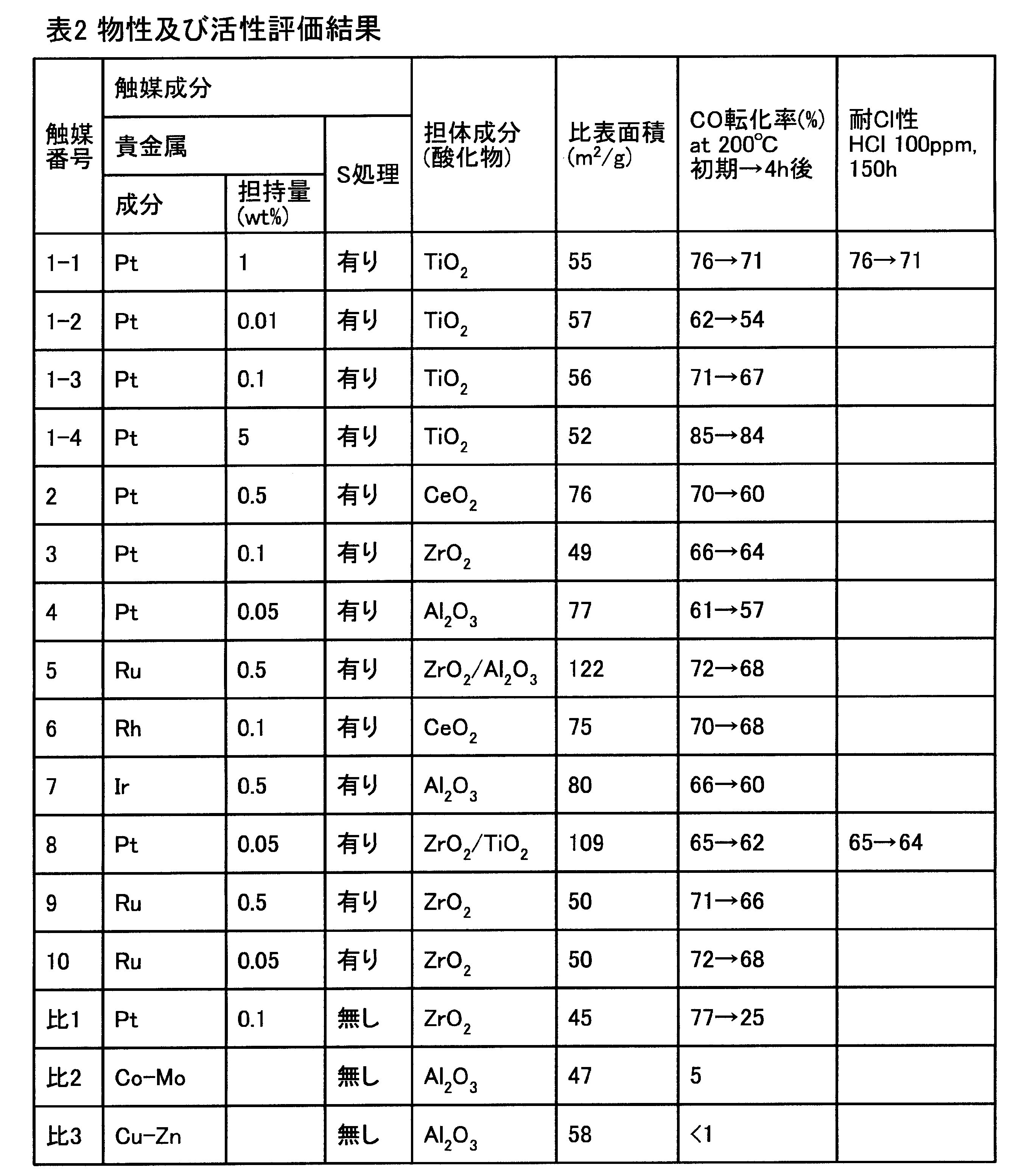
これに対し、比較例にかかる比較触媒1は、硫酸処理を施していないので、低温(200℃)においてCO転化率が大幅に低下又は失活した。比較触媒2及び3は低温では活性が低下した。
また、本試験例に係る触媒は、比表面積も比較触媒に対して増大しており、良好であった。
これにより、本試験例に係る触媒は、低温での活性が良好であることが判明した。またハロゲン耐性のCOシフト触媒として用いて有効であることが判明した。
Claims (8)
- ガス中の一酸化炭素(CO)を改質するCOシフト触媒であって、
白金(Pt)、ルテニウム(Ru)、イリジウム(Ir)、ロジウム(Rh)のいずれか一種又はこれらの混合物を活性成分とすると共に、この活性成分を担持するチタン(Ti)、アルミニウム(Al)、ジルコニウム(Zr)及びセリウム(Ce)のいずれか一種を担体とすることを特徴とするCOシフト触媒。 - 請求項1において、
前記担体が、少なくとも二種の元素が存在する複合酸化物を含むものであることを特徴とするCOシフト触媒。 - 請求項1又は2において、
活性成分の添加量が0.01~5重量%であることを特徴とするCOシフト触媒。 - 請求項1乃至3のいずれか一つにおいて、
硫酸根を残留させてなることを特徴とするCOシフト触媒。 - チタン(Ti)、アルミニウム(Al)、ジルコニウム(Zr)及びセリウム(Ce)のいずれか一種の酸化物、又はこれらの少なくとも二種の元素が存在する複合酸化物に硫酸を添加し、その後水分を蒸発させ、加熱炉で500~600℃で加熱して、担体に硫酸根を残留させ、
次いで、該硫酸根を残留させた担体に活性成分を担持させることを特徴とするCOシフト触媒の製造方法。 - 請求項5において、
前記活性成分が白金(Pt)、ルテニウム(Ru)、イリジウム(Ir)、ロジウム(Rh)のいずれか一種又はこれらの混合物であることを特徴とするCOシフト触媒の製造方法。 - 請求項1乃至4のいずれか一つのCOシフト触媒を反応塔内に充填してなることを特徴とするCOシフト反応装置。
- ガス化炉で得られたハロゲン化物を含むガス化ガス中の煤塵をフィルタで除去した後、
請求項1乃至4のいずれか一つのCOシフト触媒を用いて、COシフト反応させ、
その後、湿式スクラバ装置によりさらにCOシフト反応後のガス化ガスを浄化し、
次いで、ガス化ガス中の二酸化炭素を除去するガス化ガスの精製方法。
Priority Applications (6)
| Application Number | Priority Date | Filing Date | Title |
|---|---|---|---|
| PCT/JP2009/059068 WO2010131358A1 (ja) | 2009-05-15 | 2009-05-15 | Coシフト触媒及びその製造方法、並びにcoシフト触媒を用いたcoシフト反応装置 |
| AU2009346342A AU2009346342B2 (en) | 2009-05-15 | 2009-05-15 | CO shift catalyst, method for producing the same, and CO shift reactor using CO shift catalyst |
| US13/320,662 US20120058036A1 (en) | 2009-05-15 | 2009-05-15 | Co shift catalyst, method for manufacturing the same, and co shift reactor using co shift catalyst |
| JP2011513194A JP5595385B2 (ja) | 2009-05-15 | 2009-05-15 | Coシフト触媒及びその製造方法、並びにcoシフト触媒を用いたcoシフト反応装置 |
| DE112009004775T DE112009004775T5 (de) | 2009-05-15 | 2009-05-15 | CO-Änderungskatalysator, Verfahren zur Herstellung desselben und CO-Änderungsreaktor unter Verwendung des CO-Änderungskatalysators |
| CN2009801592598A CN102421523A (zh) | 2009-05-15 | 2009-05-15 | Co变换催化剂及其制造方法、以及使用co变换催化剂的co变换反应装置 |
Applications Claiming Priority (1)
| Application Number | Priority Date | Filing Date | Title |
|---|---|---|---|
| PCT/JP2009/059068 WO2010131358A1 (ja) | 2009-05-15 | 2009-05-15 | Coシフト触媒及びその製造方法、並びにcoシフト触媒を用いたcoシフト反応装置 |
Publications (1)
| Publication Number | Publication Date |
|---|---|
| WO2010131358A1 true WO2010131358A1 (ja) | 2010-11-18 |
Family
ID=43084748
Family Applications (1)
| Application Number | Title | Priority Date | Filing Date |
|---|---|---|---|
| PCT/JP2009/059068 Ceased WO2010131358A1 (ja) | 2009-05-15 | 2009-05-15 | Coシフト触媒及びその製造方法、並びにcoシフト触媒を用いたcoシフト反応装置 |
Country Status (6)
| Country | Link |
|---|---|
| US (1) | US20120058036A1 (ja) |
| JP (1) | JP5595385B2 (ja) |
| CN (1) | CN102421523A (ja) |
| AU (1) | AU2009346342B2 (ja) |
| DE (1) | DE112009004775T5 (ja) |
| WO (1) | WO2010131358A1 (ja) |
Families Citing this family (4)
| Publication number | Priority date | Publication date | Assignee | Title |
|---|---|---|---|---|
| EP3340349A1 (de) | 2016-12-21 | 2018-06-27 | sunfire GmbH | Schwefeltoleranter katalysator für festoxid-brennstoffzelle sowie herstellungsverfahren |
| KR102287846B1 (ko) * | 2018-12-21 | 2021-08-06 | 한화솔루션 주식회사 | 염소 제조를 위한 염화수소 산화반응용 촉매 및 이의 제조방법 |
| CN111004649A (zh) * | 2019-12-13 | 2020-04-14 | 西安润川环保科技有限公司 | 煤气精脱硫净化系统 |
| CN115646529B (zh) * | 2022-10-31 | 2024-03-12 | 湖北禾谷环保有限公司 | 一种预硫化co耐硫变换催化剂及其制备方法和应用 |
Citations (4)
| Publication number | Priority date | Publication date | Assignee | Title |
|---|---|---|---|---|
| JP2002224570A (ja) * | 2001-02-05 | 2002-08-13 | Toyota Central Res & Dev Lab Inc | Coシフト反応用触媒 |
| JP2003275588A (ja) * | 2002-03-20 | 2003-09-30 | Toyota Central Res & Dev Lab Inc | Coシフト反応用触媒 |
| JP2004160435A (ja) * | 2002-09-18 | 2004-06-10 | Nissan Motor Co Ltd | Co除去触媒 |
| JP2004331701A (ja) * | 2003-04-30 | 2004-11-25 | Clean Coal Power R & D Co Ltd | 石炭ガス化プラント、および石炭ガス化方法並びに石炭ガス化発電プラント |
Family Cites Families (4)
| Publication number | Priority date | Publication date | Assignee | Title |
|---|---|---|---|---|
| JPS592537A (ja) | 1982-06-29 | 1984-01-09 | 富士通電装株式会社 | バスシステム |
| JP2002173370A (ja) * | 2000-12-01 | 2002-06-21 | Toyota Central Res & Dev Lab Inc | チタニア系多孔体及び触媒 |
| KR100392943B1 (ko) * | 2001-05-16 | 2003-07-28 | (주)케이에이치 케미컬 | 디젤엔진 배기가스의 정화용 촉매 |
| JP4015391B2 (ja) * | 2001-09-07 | 2007-11-28 | 三菱重工業株式会社 | Coシフト触媒及びその製造方法 |
-
2009
- 2009-05-15 DE DE112009004775T patent/DE112009004775T5/de active Pending
- 2009-05-15 US US13/320,662 patent/US20120058036A1/en not_active Abandoned
- 2009-05-15 JP JP2011513194A patent/JP5595385B2/ja active Active
- 2009-05-15 CN CN2009801592598A patent/CN102421523A/zh active Pending
- 2009-05-15 AU AU2009346342A patent/AU2009346342B2/en not_active Ceased
- 2009-05-15 WO PCT/JP2009/059068 patent/WO2010131358A1/ja not_active Ceased
Patent Citations (4)
| Publication number | Priority date | Publication date | Assignee | Title |
|---|---|---|---|---|
| JP2002224570A (ja) * | 2001-02-05 | 2002-08-13 | Toyota Central Res & Dev Lab Inc | Coシフト反応用触媒 |
| JP2003275588A (ja) * | 2002-03-20 | 2003-09-30 | Toyota Central Res & Dev Lab Inc | Coシフト反応用触媒 |
| JP2004160435A (ja) * | 2002-09-18 | 2004-06-10 | Nissan Motor Co Ltd | Co除去触媒 |
| JP2004331701A (ja) * | 2003-04-30 | 2004-11-25 | Clean Coal Power R & D Co Ltd | 石炭ガス化プラント、および石炭ガス化方法並びに石炭ガス化発電プラント |
Also Published As
| Publication number | Publication date |
|---|---|
| JPWO2010131358A1 (ja) | 2012-11-01 |
| AU2009346342B2 (en) | 2014-06-12 |
| DE112009004775T5 (de) | 2012-10-11 |
| AU2009346342A1 (en) | 2011-12-08 |
| CN102421523A (zh) | 2012-04-18 |
| US20120058036A1 (en) | 2012-03-08 |
| JP5595385B2 (ja) | 2014-09-24 |
Similar Documents
| Publication | Publication Date | Title |
|---|---|---|
| JP5550715B2 (ja) | Coシフト触媒、coシフト反応装置及びガス化ガスの精製方法 | |
| JP5404774B2 (ja) | Coシフト触媒、coシフト反応装置及びガス化ガスの精製方法 | |
| JP6005251B2 (ja) | Coシフト触媒の製造方法及びガス化ガスの精製方法 | |
| JP5955026B2 (ja) | 硫化カルボニルおよびシアン化水素の加水分解用触媒ならびに酸化チタン系組成物の使用 | |
| JP7445925B2 (ja) | 燃焼システム | |
| US9238208B2 (en) | CO shift reaction apparatus and gasification gas refining system | |
| JP5595385B2 (ja) | Coシフト触媒及びその製造方法、並びにcoシフト触媒を用いたcoシフト反応装置 | |
| JP2011157486A (ja) | ガス化ガス精製システム | |
| WO2019130899A1 (ja) | 硫化カルボニルの加水分解用触媒及びその製造方法 | |
| CN104507572B (zh) | Co转化催化剂、co转化反应装置及气化气的精制方法 | |
| JP6025870B2 (ja) | Coシフト触媒、coシフト反応装置及びガス化ガスの精製方法 | |
| JP5968465B2 (ja) | Coシフト触媒、coシフト反応装置及びガス化ガスの精製方法 |
Legal Events
| Date | Code | Title | Description |
|---|---|---|---|
| WWE | Wipo information: entry into national phase |
Ref document number: 200980159259.8 Country of ref document: CN |
|
| 121 | Ep: the epo has been informed by wipo that ep was designated in this application |
Ref document number: 09844631 Country of ref document: EP Kind code of ref document: A1 |
|
| WWE | Wipo information: entry into national phase |
Ref document number: 2011513194 Country of ref document: JP |
|
| WWE | Wipo information: entry into national phase |
Ref document number: 2009346342 Country of ref document: AU |
|
| WWE | Wipo information: entry into national phase |
Ref document number: 13320662 Country of ref document: US Ref document number: 1120090047750 Country of ref document: DE Ref document number: 112009004775 Country of ref document: DE |
|
| ENP | Entry into the national phase |
Ref document number: 2009346342 Country of ref document: AU Date of ref document: 20090515 Kind code of ref document: A |
|
| 122 | Ep: pct application non-entry in european phase |
Ref document number: 09844631 Country of ref document: EP Kind code of ref document: A1 |