WO2010128565A1 - 空気入りタイヤの製造方法 - Google Patents
空気入りタイヤの製造方法 Download PDFInfo
- Publication number
- WO2010128565A1 WO2010128565A1 PCT/JP2009/061053 JP2009061053W WO2010128565A1 WO 2010128565 A1 WO2010128565 A1 WO 2010128565A1 JP 2009061053 W JP2009061053 W JP 2009061053W WO 2010128565 A1 WO2010128565 A1 WO 2010128565A1
- Authority
- WO
- WIPO (PCT)
- Prior art keywords
- mold
- tire
- molded body
- primary molded
- inner peripheral
- Prior art date
Links
Images


Classifications
-
- B—PERFORMING OPERATIONS; TRANSPORTING
- B29—WORKING OF PLASTICS; WORKING OF SUBSTANCES IN A PLASTIC STATE IN GENERAL
- B29D—PRODUCING PARTICULAR ARTICLES FROM PLASTICS OR FROM SUBSTANCES IN A PLASTIC STATE
- B29D30/00—Producing pneumatic or solid tyres or parts thereof
- B29D30/06—Pneumatic tyres or parts thereof (e.g. produced by casting, moulding, compression moulding, injection moulding, centrifugal casting)
- B29D30/08—Building tyres
- B29D30/20—Building tyres by the flat-tyre method, i.e. building on cylindrical drums
- B29D30/24—Drums
- B29D30/26—Accessories or details, e.g. membranes, transfer rings
- B29D30/2607—Devices for transferring annular tyre components during the building-up stage, e.g. from the first stage to the second stage building drum
-
- B—PERFORMING OPERATIONS; TRANSPORTING
- B29—WORKING OF PLASTICS; WORKING OF SUBSTANCES IN A PLASTIC STATE IN GENERAL
- B29C—SHAPING OR JOINING OF PLASTICS; SHAPING OF MATERIAL IN A PLASTIC STATE, NOT OTHERWISE PROVIDED FOR; AFTER-TREATMENT OF THE SHAPED PRODUCTS, e.g. REPAIRING
- B29C33/00—Moulds or cores; Details thereof or accessories therefor
- B29C33/02—Moulds or cores; Details thereof or accessories therefor with incorporated heating or cooling means
-
- B—PERFORMING OPERATIONS; TRANSPORTING
- B29—WORKING OF PLASTICS; WORKING OF SUBSTANCES IN A PLASTIC STATE IN GENERAL
- B29C—SHAPING OR JOINING OF PLASTICS; SHAPING OF MATERIAL IN A PLASTIC STATE, NOT OTHERWISE PROVIDED FOR; AFTER-TREATMENT OF THE SHAPED PRODUCTS, e.g. REPAIRING
- B29C35/00—Heating, cooling or curing, e.g. crosslinking or vulcanising; Apparatus therefor
- B29C35/02—Heating or curing, e.g. crosslinking or vulcanizing during moulding, e.g. in a mould
-
- B—PERFORMING OPERATIONS; TRANSPORTING
- B29—WORKING OF PLASTICS; WORKING OF SUBSTANCES IN A PLASTIC STATE IN GENERAL
- B29D—PRODUCING PARTICULAR ARTICLES FROM PLASTICS OR FROM SUBSTANCES IN A PLASTIC STATE
- B29D30/00—Producing pneumatic or solid tyres or parts thereof
- B29D30/06—Pneumatic tyres or parts thereof (e.g. produced by casting, moulding, compression moulding, injection moulding, centrifugal casting)
- B29D30/0601—Vulcanising tyres; Vulcanising presses for tyres
- B29D30/0654—Flexible cores therefor, e.g. bladders, bags, membranes, diaphragms
-
- B—PERFORMING OPERATIONS; TRANSPORTING
- B29—WORKING OF PLASTICS; WORKING OF SUBSTANCES IN A PLASTIC STATE IN GENERAL
- B29D—PRODUCING PARTICULAR ARTICLES FROM PLASTICS OR FROM SUBSTANCES IN A PLASTIC STATE
- B29D30/00—Producing pneumatic or solid tyres or parts thereof
- B29D30/06—Pneumatic tyres or parts thereof (e.g. produced by casting, moulding, compression moulding, injection moulding, centrifugal casting)
- B29D30/0681—Parts of pneumatic tyres; accessories, auxiliary operations
-
- B—PERFORMING OPERATIONS; TRANSPORTING
- B29—WORKING OF PLASTICS; WORKING OF SUBSTANCES IN A PLASTIC STATE IN GENERAL
- B29D—PRODUCING PARTICULAR ARTICLES FROM PLASTICS OR FROM SUBSTANCES IN A PLASTIC STATE
- B29D30/00—Producing pneumatic or solid tyres or parts thereof
- B29D30/06—Pneumatic tyres or parts thereof (e.g. produced by casting, moulding, compression moulding, injection moulding, centrifugal casting)
- B29D30/08—Building tyres
- B29D30/10—Building tyres on round cores, i.e. the shape of the core is approximately identical with the shape of the completed tyre
-
- B—PERFORMING OPERATIONS; TRANSPORTING
- B29—WORKING OF PLASTICS; WORKING OF SUBSTANCES IN A PLASTIC STATE IN GENERAL
- B29D—PRODUCING PARTICULAR ARTICLES FROM PLASTICS OR FROM SUBSTANCES IN A PLASTIC STATE
- B29D30/00—Producing pneumatic or solid tyres or parts thereof
- B29D30/06—Pneumatic tyres or parts thereof (e.g. produced by casting, moulding, compression moulding, injection moulding, centrifugal casting)
- B29D30/08—Building tyres
- B29D30/20—Building tyres by the flat-tyre method, i.e. building on cylindrical drums
- B29D30/24—Drums
- B29D30/244—Drums for manufacturing substantially cylindrical tyre components with cores or beads, e.g. carcasses
- B29D30/246—Drums for the multiple stage building process, i.e. the building-up of the cylindrical carcass is realised on one drum and the toroidal expansion is realised after transferring on another drum
-
- B—PERFORMING OPERATIONS; TRANSPORTING
- B60—VEHICLES IN GENERAL
- B60C—VEHICLE TYRES; TYRE INFLATION; TYRE CHANGING; CONNECTING VALVES TO INFLATABLE ELASTIC BODIES IN GENERAL; DEVICES OR ARRANGEMENTS RELATED TO TYRES
- B60C1/00—Tyres characterised by the chemical composition or the physical arrangement or mixture of the composition
- B60C1/0008—Compositions of the inner liner
-
- B—PERFORMING OPERATIONS; TRANSPORTING
- B60—VEHICLES IN GENERAL
- B60C—VEHICLE TYRES; TYRE INFLATION; TYRE CHANGING; CONNECTING VALVES TO INFLATABLE ELASTIC BODIES IN GENERAL; DEVICES OR ARRANGEMENTS RELATED TO TYRES
- B60C5/00—Inflatable pneumatic tyres or inner tubes
- B60C5/12—Inflatable pneumatic tyres or inner tubes without separate inflatable inserts, e.g. tubeless tyres with transverse section open to the rim
- B60C5/14—Inflatable pneumatic tyres or inner tubes without separate inflatable inserts, e.g. tubeless tyres with transverse section open to the rim with impervious liner or coating on the inner wall of the tyre
-
- B—PERFORMING OPERATIONS; TRANSPORTING
- B29—WORKING OF PLASTICS; WORKING OF SUBSTANCES IN A PLASTIC STATE IN GENERAL
- B29D—PRODUCING PARTICULAR ARTICLES FROM PLASTICS OR FROM SUBSTANCES IN A PLASTIC STATE
- B29D30/00—Producing pneumatic or solid tyres or parts thereof
- B29D30/06—Pneumatic tyres or parts thereof (e.g. produced by casting, moulding, compression moulding, injection moulding, centrifugal casting)
- B29D30/0601—Vulcanising tyres; Vulcanising presses for tyres
- B29D30/0645—Devices for inserting vulcanising cores, i.e. bladders, into the tyres; Closing the press in combination herewith
- B29D2030/0647—Supporting or transferring tyres using an assembly of a bladder and side rings
-
- B—PERFORMING OPERATIONS; TRANSPORTING
- B29—WORKING OF PLASTICS; WORKING OF SUBSTANCES IN A PLASTIC STATE IN GENERAL
- B29D—PRODUCING PARTICULAR ARTICLES FROM PLASTICS OR FROM SUBSTANCES IN A PLASTIC STATE
- B29D30/00—Producing pneumatic or solid tyres or parts thereof
- B29D30/06—Pneumatic tyres or parts thereof (e.g. produced by casting, moulding, compression moulding, injection moulding, centrifugal casting)
- B29D30/0601—Vulcanising tyres; Vulcanising presses for tyres
- B29D30/0654—Flexible cores therefor, e.g. bladders, bags, membranes, diaphragms
- B29D2030/0655—Constructional or chemical features of the flexible cores
-
- B—PERFORMING OPERATIONS; TRANSPORTING
- B29—WORKING OF PLASTICS; WORKING OF SUBSTANCES IN A PLASTIC STATE IN GENERAL
- B29D—PRODUCING PARTICULAR ARTICLES FROM PLASTICS OR FROM SUBSTANCES IN A PLASTIC STATE
- B29D30/00—Producing pneumatic or solid tyres or parts thereof
- B29D30/06—Pneumatic tyres or parts thereof (e.g. produced by casting, moulding, compression moulding, injection moulding, centrifugal casting)
- B29D30/0681—Parts of pneumatic tyres; accessories, auxiliary operations
- B29D2030/0682—Inner liners
-
- B—PERFORMING OPERATIONS; TRANSPORTING
- B60—VEHICLES IN GENERAL
- B60C—VEHICLE TYRES; TYRE INFLATION; TYRE CHANGING; CONNECTING VALVES TO INFLATABLE ELASTIC BODIES IN GENERAL; DEVICES OR ARRANGEMENTS RELATED TO TYRES
- B60C5/00—Inflatable pneumatic tyres or inner tubes
- B60C5/12—Inflatable pneumatic tyres or inner tubes without separate inflatable inserts, e.g. tubeless tyres with transverse section open to the rim
- B60C5/14—Inflatable pneumatic tyres or inner tubes without separate inflatable inserts, e.g. tubeless tyres with transverse section open to the rim with impervious liner or coating on the inner wall of the tyre
- B60C2005/145—Inflatable pneumatic tyres or inner tubes without separate inflatable inserts, e.g. tubeless tyres with transverse section open to the rim with impervious liner or coating on the inner wall of the tyre made of laminated layers
Definitions
- the present invention relates to a method for manufacturing a pneumatic tire, and more particularly, a pneumatic tire having high uniformity and having an inner layer that is lightweight and has excellent air permeation prevention performance by effectively using a rigid inner mold.
- the present invention relates to a method of manufacturing a pneumatic tire that can be manufactured with productivity.
- the green tire is only pressed from the outside by the vulcanization mold during vulcanization, the pressing force acting on the inner peripheral surface of the green tire is reduced. Therefore, for example, even if the volume of the tire constituent member is uneven on the tire inner peripheral surface, it is difficult to sufficiently correct this unevenness, and there is a limit to improving the uniformity of the vulcanized tire.
- butyl rubber is mainly used for the inner layer (innermost peripheral surface) of the green tire.
- the inner layer made of butyl rubber is disadvantageous in reducing the weight of the tire because it requires a certain thickness in order to ensure sufficient air permeation prevention performance. Therefore, there has been a demand for an inner layer that is excellent in air permeation prevention performance and lightweight.
- the rigid inner mold is disposed inside the vulcanizing mold together with the green tire during vulcanization.
- the rigid inner mold is disposed inside the vulcanizing mold together with the green tire during vulcanization.
- the object of the present invention is to produce a pneumatic tire that can effectively produce a pneumatic tire excellent in uniformity, having an inner layer that is lightweight and excellent in air permeation prevention performance, by effectively using a rigid inner mold. It is to provide a method.
- a method for producing a pneumatic tire according to the present invention includes a cylindrical body in which at least a carcass material is disposed on the outer peripheral side of a film made of a thermoplastic elastomer composition or a thermoplastic elastomer composition obtained by blending an elastomer with a thermoplastic resin.
- a cylinder formed of a plurality of divided bodies is formed by molding a primary molded body with bead rings fitted to both ends in the width direction of the sheet, and holding the primary molded body by suction and holding on the inner peripheral surface of the transfer holding mold.
- the suction by the transfer holding mold is stopped and the primary molded body is transferred to the outer peripheral surface of the rigid inner mold.
- both ends of the carcass material in the width direction are turned up, and another tire constituent member is laminated on the outer peripheral surface of the primary molded body to form a green tire, and the rigid inner mold is removed from the green tire.
- the green tire is placed inside the vulcanization mold installed in the vulcanizer, the vulcanization mold is heated to a predetermined temperature, and the film is heated while being pressurized and inflated from the inner peripheral side. The green tire is vulcanized and the film is tightly bonded to the inner peripheral surface of the tire.
- a bladder that has the same shape as the inner peripheral cavity of the green tire when expanded is attached to the vulcanization mold. This is performed by inflating with a heating fluid in the inner peripheral cavity of the green tire disposed inside. Alternatively, the heating fluid is directly injected into the inner peripheral surface of the green tire disposed inside the vulcanization mold.
- the transfer holding mold is arranged on the outer peripheral side of the primary molded body, and from the inner peripheral side of the primary molded body. The primary molded body can also be sucked from the outer peripheral side by the transfer holding mold while applying pressure.
- the film is inflated by applying a pressure of 0.01 MPa to 3.0 MPa from the inner peripheral side. Further, for example, the green tire disposed inside the vulcanization mold is vulcanized while sucking air from the inside of the vulcanization mold to the outside.
- bead rings are externally fitted to both ends in the width direction of a cylindrical body in which at least a carcass material is disposed on the outer peripheral side of a film made of a thermoplastic resin or a thermoplastic elastomer composition.
- a primary molded body is molded, and the primary molded body is sucked and held on the inner peripheral surface of the transfer holding mold, and a cylindrical rigid inner mold composed of a plurality of divided bodies is formed into the primary molded body. Then, the primary molded body can be smoothly transferred to the outer peripheral surface of the rigid inner mold without damaging the film on the inner peripheral surface by stopping the suction by the transfer holding mold.
- both ends in the width direction of the carcass material are turned up on the rigid inner mold, and another tire constituent member is laminated on the outer peripheral surface of the primary molded body to form a green tire.
- the green tire is placed inside the vulcanization mold installed in the vulcanizer and vulcanized, so that the rigid inner mold can be used freely during vulcanization. Therefore, the number of green tires that can be molded with a single rigid inner mold in a predetermined time is increased, and productivity can be improved by effectively using the rigid inner mold.
- the green tire disposed inside the vulcanizing mold is heated and vulcanized while heating the vulcanizing mold to a predetermined temperature and pressurizing and inflating the film from the inner peripheral side, the tire constituent member When the unvulcanized rubber is pressed toward the inner peripheral surface of the vulcanizing mold, it flows in the circumferential direction, and even if the volume of the tire constituent member is uneven, the unevenness is corrected. This makes it possible to improve the uniformity of the tire to be manufactured.
- the film is tightly bonded to the inner peripheral surface of the tire to form the inner layer of the tire. Since this film is made of a thermoplastic resin or thermoplastic elastomer composition, it is lighter and has better gas barrier properties than conventional inner layers made of butyl rubber, and the manufactured tire is lightweight and has excellent air permeation prevention Performance can be obtained.
- FIG. 1 is a longitudinal sectional view illustrating a step of forming a primary molded body.
- FIG. 2 is a cross-sectional view taken along the line AA in FIG.
- FIG. 3 is a vertical cross-sectional view illustrating a state in which a distance adjusting plate is connected to the carcass fixing ring of FIG.
- FIG. 4 is an upper half vertical cross-sectional view illustrating a state where an inflation mold is inserted into the primary molded body.
- FIG. 5 is an upper half vertical cross-sectional view illustrating a state where the primary molded body is bulged and deformed on the outer peripheral side.
- 6 is a longitudinal sectional view illustrating the internal structure of the inflation mold shown in FIG. FIG.
- FIG. 7 is an upper half longitudinal sectional view illustrating the step of sucking and holding the primary molded body by the transfer holding mold.
- FIG. 8 is an upper half longitudinal sectional view illustrating a step of inserting a rigid inner mold into the primary molded body.
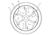
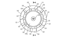
- FIG. 9 is a front view of the rigid inner mold.
- 10 is a cross-sectional view taken along the line BB of FIG.
- FIG. 11 is an upper half vertical cross-sectional view illustrating a rigid inner mold onto which the primary molded body has been transferred.
- FIG. 12 is an upper half vertical cross-sectional view illustrating a state where a green tire is molded on the outer peripheral surface of the rigid inner mold.
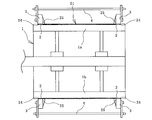
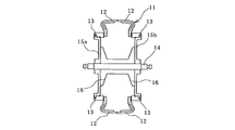
- FIG. 13 is an upper half longitudinal sectional view illustrating a step of removing the rigid inner mold from the molded green tire.
- FIG. 14 is an upper half longitudinal cross section illustrating the next step of FIG.
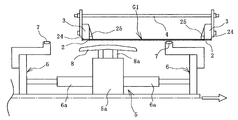
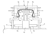
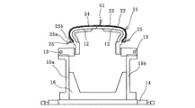
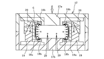
- FIG. 15 is a longitudinal sectional view illustrating a state in which a green tire is vulcanized.
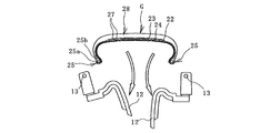
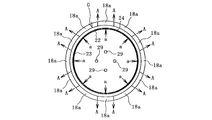
- 16 is a cross-sectional view taken along the line CC of FIG.
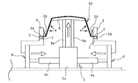
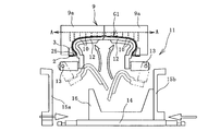
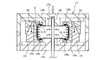
- FIG. 17 is a longitudinal sectional view illustrating a state in which a green tire is vulcanized using a bladder.
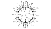
- 18 is a sectional view taken along the line DD of FIG.
- FIG. 19 is a meridian half cross-sectional view illustrating a pneumatic tire manufactured according to the present invention.
- FIG. 19 illustrates a pneumatic tire 21 manufactured according to the present invention.
- a carcass material 24 is mounted between a pair of bead rings 25, and the carcass material 24 is folded around a bead core 25a with a bead filler 25b sandwiched from the inside to the outside.
- a tie rubber 23 and a film 22 are laminated on the inner peripheral side of the carcass material 24.
- the innermost film 22 is an inner layer that prevents air permeation, and the film 22 and the carcass material 24 are satisfactorily joined by an intervening tie rubber 23.
- a rubber member constituting the sidewall portion 26 and a rubber member constituting the tread portion 28 are provided on the outer peripheral side of the carcass material 24.
- a belt layer 27 is provided on the outer peripheral side of the carcass material 24 of the tread portion 28 over the entire circumference in the tire circumferential direction.
- the reinforcing cords constituting the belt layer 27 are arranged to be inclined with respect to the tire circumferential direction, and the laminated upper and lower belt layers 27 are arranged so that the reinforcing cords cross each other.
- the pneumatic tire 1 manufactured according to the present invention is not limited to the structure shown in FIG. 19 and can be applied to manufacturing pneumatic tires having other structures.
- This pneumatic tire 11 has a major structural feature in that the inner layer is replaced with a film 22 from conventional butyl rubber.
- the thickness of the film 22 is, for example, 0.005 mm to 0.2 mm.
- the film 22 used in the present invention is composed of a thermoplastic resin or a thermoplastic elastomer composition obtained by blending an elastomer in a thermoplastic resin.
- thermoplastic resin examples include polyamide-based resins [for example, nylon 6 (N6), nylon 66 (N66), nylon 46 (N46), nylon 11 (N11), nylon 12 (N12), nylon 610 (N610), nylon 612 (N612), nylon 6/66 copolymer (N6 / 66), nylon 6/66/610 copolymer (N6 / 66/610), nylon MXD6, nylon 6T, nylon 6 / 6T copolymer, nylon 66 / PP copolymer, nylon 66 / PPS copolymer], polyester resin (for example, polybutylene terephthalate (PBT), polyethylene terephthalate (PET), polyethylene isophthalate (PEI), polybutylene terephthalate / tetramethylene glycol copolymer) Copolymer, PET / PEI copolymer Aromatic polyesters such as polyarylate (PAR), polybutylene naphthalate (PBN), liquid crystal polyester, polyoxyalky
- elastomers include diene rubbers and hydrogenated products thereof (eg, NR, IR, epoxidized natural rubber, SBR, BR (high cis BR and low cis BR), NBR, hydrogenated NBR, hydrogenated SBR), olefins Rubber (for example, ethylene propylene rubber (EPDM, EPM), maleic acid modified ethylene propylene rubber (M-EPM)), butyl rubber (IIR), isobutylene and aromatic vinyl or diene monomer copolymer, acrylic rubber (ACM), Ionomer, halogen-containing rubber [for example, Br-IIR, Cl-IIR, brominated isobutylene paramethylstyrene copolymer (Br-IPMS), chloroprene rubber (CR), hydrin rubber (CHC, CHR), chlorosulfonated polyethylene (CSM) ), Chlorinated polyethylene (CM), ma Inacid-modified chlorinated polyethylene (M-CM)
- the weight ratio between the thermoplastic resin component (A) and the elastomer component (B) is appropriately determined depending on the balance of film thickness and flexibility.
- the weight ratio of the thermoplastic resin component (A) to the total weight of the thermoplastic resin component (A) and the elastomer component (B) is preferably 10% to 90%, more preferably 20% to 85%.
- thermoplastic elastomer composition used in the present invention in addition to the essential components (A) and (B), other polymers and compounding agents such as a compatibilizer can be mixed as a third component.
- a compatibilizer can be mixed as a third component.
- the purpose of mixing other polymers is to improve the compatibility between the thermoplastic resin component and the elastomer component, to improve the film molding processability of the material, to improve heat resistance, to reduce costs, etc.
- the material used for this include polyethylene, polypropylene, polystyrene, ABS, SBS, and polycarbonate.
- the film 22 made of the thermoplastic resin or the thermoplastic elastomer composition as described above has a good gas barrier property because of excellent surface orientation of the polymer chain.
- the film 22 having better gas barrier properties than butyl rubber becomes the inner layer, so that excellent air permeation prevention performance is obtained as compared with the conventional pneumatic tire. be able to.
- the thickness of the conventional inner layer made of butyl rubber is, for example, 0.5 mm to 5.0 mm, but the thickness of the film 22 is about 0.005 mm to 0.2 mm. Therefore, the inner layer can be significantly reduced in weight, which greatly contributes to reducing the weight of the pneumatic tire 21.
- the primary molded body G1 is molded using the primary molding drum 1 illustrated in FIGS.
- the primary molding drum 1 is composed of a plurality of segments 1a and 1b divided in the circumferential direction, and each of the two types of segments 1a and 1b is movable in the radial direction.
- the primary molding drum 1 is a cylindrical body that expands and contracts.
- the number of segments 1a and 1b is six in this embodiment, but is not limited to this.
- the fixing ring 2 is fitted on both ends of the primary molding drum 1 in the width direction, and the diameters of the segments 1a are moved to make the primary molding drum 1 cylindrical.
- a cylindrical body is formed by arranging the film 22, the tie rubber 23 and the carcass material 24 in this order on the outer peripheral surface of the cylindrical primary forming drum 1.
- the carcass material 24 protrudes on both sides in the width direction from the film 22 and the tie rubber 23.
- the cylindrical film 22 is extrapolated to the primary molding drum 1 to form a cylindrical shape.
- the belt-like film 22 is wound around the outer peripheral surface of the primary molding drum 1 to form a cylindrical shape.
- the belt-like film 22 and the tie rubber 23, or the belt-like film 22, the tie rubber 23 and the carcass material 24 are laminated in advance to form a laminate, and this laminate is used as the primary molding drum 1. It can also be wound around the outer peripheral surface into a cylindrical shape.
- bead rings 25 are arranged on the outer peripheral sides of both end portions in the width direction of the carcass material 24, and then the carcass fixing rings 3 are arranged on the outer peripheral sides of both end portions in the width direction of the carcass material 24.
- the portion is fixed between the fixing ring 2 and the carcass fixing ring 3.
- Each bead ring 25 is fixed inside the carcass fixing ring 3.
- the primary molded body G1 in which the bead ring 25 is fitted on the both ends in the width direction of the cylindrical body in which at least the carcass material 24 is disposed on the outer peripheral side of the film 22 is formed.
- the respective carcass fixing rings 3 are connected by the interval adjusting plate 4.
- the interval adjusting plate 4 is attached to the carcass fixing ring 3 using a fixing member such as a bolt.
- the diameters of the segments 1a and 1b are reduced, and the primary molding drum 1 is extracted from the cylindrical primary molded body G1.
- the primary molded body G1 is held by the fixing ring 2, the carcass fixing ring 3, and the interval adjusting plate 4.
- a cylindrical inflation mold 5 is inserted into the primary molded body G1.
- the inflation mold 5 has disk-shaped side plates 6 on both sides in the width direction of the core portion 5 a, and the core portion 5 a has a plurality of circumferentially divided presses.
- a plate 8 is provided.
- the number of pressing plates 8 is five in this embodiment, but is not limited to this.
- Each side plate 6 is moved in the width direction by a cylinder 6a provided in the core portion 5a.
- a seal member 7 that expands and contracts is provided on the outer peripheral edge of the side plate 6.
- Each pressing plate 8 is configured to move in the radial direction by a cylinder 8a provided in the core portion 5a.
- the outer peripheral surface of the pressing plate 8 has substantially the same shape as the profile of the inner peripheral surface of the tire to be manufactured.
- the seal member 7 is expanded and the peripheral portions of the bead ring 25 (the fixing ring 2 and the carcass fixing ring 3) are firmly fixed by the side plate 6. To do. Thereafter, the distance adjusting plate 4 is removed from the carcass fixing ring 3.
- each cylinder 6 a is made free, the rod of each cylinder 8 a is extended, and the pressing plate 8 is pressed against the inner peripheral surface of the primary molded body G ⁇ b> 1.
- the primary molded body G1 is bulged and deformed to the outer peripheral side by slightly applying pressure by injecting air a.
- each bead ring 25 (side plate 6) moves so as to be close to each other.
- the transfer holding die 9 is disposed on the outer peripheral side of the primary molded body G1.
- a suction means such as a vacuum pump is detachably connected to the transfer holding die 9.
- the transfer holding mold 9 is constituted by a divided mold 9a divided into two in the width direction.
- the inner peripheral surface of the transfer holding die 9 is formed in an annular shape, and a plurality of suction holes 10 communicating with the suction means are formed.
- a cylindrical rigid inner mold 11 is inserted into the primary molded body.
- the detailed structure of the rigid inner mold 11 will be described later.
- the divided body 12 on one side divided in the width direction is first set with the rotation mechanism 13 as the rotation center. Then, the divided body 12 on the other side is similarly moved and assembled in an annular shape. By such an assembling operation, the rigid inner mold 11 is inserted into the primary molded body G1.
- the suction by the transfer holding die 9 is stopped, and the primary compact G1 is transferred to the outer peripheral surface of the rigid inner die 11.
- the transfer holding mold 9 is separated from each divided mold 9a and removed from the primary molded body G1.
- the primary molded body G1 is transferred to the outer peripheral surface of the rigid inner mold 11 while being sucked and held on the inner peripheral surface of the transfer holding mold 9, so that the film 22 functioning as an inner layer is obtained. Smooth transfer work can be performed without damaging the.
- the rigid inner mold 11 has a cylindrical shape as illustrated in FIGS. 9 and 10, and includes a divided body 12 that is divided into a plurality in the circumferential direction.
- the divided body 12 is further configured to divide the cylindrical peripheral surface into two in the width direction.
- Examples of the material of the rigid inner mold 11 include metals such as aluminum and aluminum alloys.
- These divided bodies 12 are formed in a cylindrical shape by being fixed to the peripheral edge portions of the opposing disk-shaped support plates 15a and 15b via a rotation mechanism 13. That is, the divided body 12 on one side obtained by dividing the cylindrical circumferential surface into two in the width direction is annularly disposed along the peripheral edge of the support plate 15a on one side of the opposed support plates 15a and 15b.
- the other divided body 12 whose surface is divided into two in the width direction is annularly arranged along the peripheral edge portion of the other support plate 15b.
- the central axis 14 is fixed so as to pass through the center positions of the opposing support plates 15a and 15b.
- the center shaft 14 and the pair of support plates 15 a and 15 b are fixed via support ribs 16 fixed to the outer peripheral surface of the center shaft 14.
- the rigid inner mold 11 composed of a plurality of divided bodies 12 formed in a cylindrical shape moves so that each of the divided bodies 12 expands and contracts with the rotation mechanism 13 as a rotation center. .
- the cylindrical rigid inner mold 11 on which the primary molded body G ⁇ b> 1 is transferred is attached to a molding apparatus or the like with the central shaft 14 being pivotally supported. It is done.
- the both ends of the carcass member 24 in the width direction are turned up on the rigid inner mold 11, and the rubber member of the sidewall portion 26, the belt layer 27, and the tread portion 28 are formed on the outer peripheral surface of the primary molded body G1.
- the green tire G is formed as shown in FIG.
- the green tire G is not formed with a tread pattern, but is formed in the same shape and shape as the pneumatic tire 21 to be manufactured.
- the rigid inner mold 11 is removed from the molded green tire G.
- the rigid inner mold 11 is removed by holding the rotating mechanisms 13 of the respective divided bodies 12 from both sides in the width direction of the rigid inner mold 11, and the respective rotating mechanisms 13 and the support plates 15a. , 15b is released.
- one support plate 15a is removed from the central shaft 14, and the one support plate 15a and the other support plate 15b to which the rotary shaft 14 is fixed are moved to the outside of the green tire G.
- the division body 12 on one side in the width direction (right side in FIG. 14) is rotated inside the tire so as to reduce the diameter of the cylindrical rigid inner mold 11 around the rotation mechanism 13.
- the divided body 12 on the other side in the width direction (left side in FIG. 14) is rotated inward of the tire so as to reduce the diameter of the cylindrical rigid inner mold 11 around the rotation mechanism 13.
- the divided body 12 is rotated inside the tire and then moved outside the green tire G to be removed.
- a procedure reverse to the procedure illustrated in FIGS. 13 and 14 may be performed.
- the rigid inner mold 11 can be smoothly removed as compared with a pneumatic tire having a butyl rubber as an inner layer.
- the excellent peelability of the film 22 eliminates the need for additional work such as applying a release agent between the inner peripheral surface of the green tire and the rigid inner mold 11 (divided body 12). Has become advantageous.
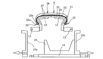
- the molded green tire G is disposed at a predetermined position inside the vulcanization mold installed in the vulcanizer 17.
- This vulcanization mold is composed of a plurality of sectors 18a divided in the tire circumferential direction and upper and lower annular side plates 18b, 18b.
- a lower side plate 18b is fixed to the lower housing 17b on which each sector 18a is placed, and a back segment 19 having an inclined surface is attached to the back surface of the sector 18a.
- a guide member 20 having an inclined surface and an upper side plate 18b are fixed to the upper housing 17a.
- each sector 18a that has been in the expanded state moves so as to be reduced in diameter and is assembled in an annular shape.
- An upper side plate 18b that has moved downward is disposed at the upper inner peripheral edge of the sector 18a that is assembled in an annular shape. The upper bead portion of the green tire G is in contact with the upper side plate 18b.
- the upper and lower bead portions of the green tire G are in close contact with the upper and lower side plates 18b and sealed. Thereby, the inner peripheral cavity of the green tire G is enclosed and sealed by the vulcanization mold and the upper housing 17a and the lower housing 17b.
- the vulcanization mold is heated to a predetermined temperature, and heated fluid such as heated air a is injected into the inner peripheral cavity of the green tire G through the communication passage 29 provided in the lower housing 17b.
- heated fluid such as heated air a is injected into the inner peripheral cavity of the green tire G through the communication passage 29 provided in the lower housing 17b.
- the heating fluid is directly injected into the inner peripheral surface (inner peripheral cavity) of the film 22 to apply pressure to inflate the film 22 and heat it to vulcanize the green tire G.
- the air a to be supplied general air or nitrogen gas can be exemplified.
- the pressure for inflating the film 22 is, for example, about 0.01 MPa to 3.0 MPa.
- the unvulcanized rubber in the tire constituent member is pressed toward the inner peripheral surface of the sector (vulcanization mold) 18a as illustrated in FIG. It flows in the circumferential direction of the sector 18a. Therefore, even if the volume of the tire constituent member of the green tire G is uneven, the unevenness is corrected and the uniformity of the pneumatic tire 21 to be manufactured can be improved.
- the film 22 is bonded to the tire inner peripheral surface (rubber member disposed on the outer peripheral side of the film 22) together with the vulcanization of the green tire G, and the pneumatic tire 21 having the film 22 as an inner layer is manufactured. . In this way, it is possible to efficiently manufacture the pneumatic tire 21 having an inner layer that is lightweight and excellent in air permeation prevention performance and excellent in uniformity.
- the green tire G may be vulcanized in a negative pressure state by forcibly sucking air A from the inside of the vulcanization mold to the outside.
- a vacuum pump is used to evacuate through the mating surfaces of adjacent sectors (vulcanization molds) 18a. According to this, since the air between the laminated tire constituent members and the air in the tire constituent members (rubber members) can be removed, it is possible to prevent inconveniences due to the pneumatic entry of the manufactured pneumatic tire 21, and the quality. Can be improved.
- an adhesive layer may be provided in advance on the outer peripheral surface of the film 22.
- the tie rubber 23 can be arranged not only to cover the entire outer periphery of the film 22 but also to cover a part of the outer peripheral surface of the film 22. The tie rubber 23 can be omitted if a certain bonding strength between the film 22 and the member on the outer peripheral side of the film 22 can be secured.
- the film 22 functions as a conventional bladder, the maintenance of the bladder becomes unnecessary, which is advantageous for improving productivity.
- the vulcanization mold can be heated by various heat sources.
- an electric heating element embedded in the vulcanization mold can be used.
- Precise temperature control can be performed by heating with an electric heating element.
- the outer peripheral surface of the green tire G is formed into a predetermined shape by the sector 18a, and the inner peripheral surface is formed in close contact with the inflated film 22. Therefore, unnecessary marks may remain on the inner peripheral surface of the vulcanized pneumatic tire, such as a manufacturing method using a conventional rubber bladder or a manufacturing method in which a green tire is pressed against the outer peripheral surface of a rigid inner mold.
- the appearance quality is also improved because it has a smooth surface.
- the rigid inner mold 11 is not disposed inside the vulcanization mold, so that the rigid inner mold 11 can be freely used during vulcanization. Therefore, the number of green tires G that can be molded in a predetermined time with one rigid inner mold 11 is increased, and productivity can be improved by effectively utilizing the rigid inner mold 11. Accordingly, the number of rigid inner dies 11 to be prepared can be reduced.
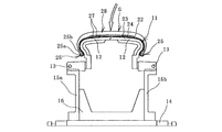
- the green tire G molded using the rigid inner mold 11 can be vulcanized using a bladder 31 as illustrated in FIG.
- Two disc-shaped bladder holding plates 32 are attached to a center post 30 that is inserted into a cylindrical hole formed at the center of the upper housing 17a and the lower housing 17b.
- a bladder 31 formed by embedding an elastic material such as rubber or a reinforcing material such as a canvas layer in the elastic material is fixed to the outer peripheral edge of the bladder holding plate 32.
- the bladder 31 is formed to have the same shape as the inner peripheral cavity of the green tire G when expanded. That is, the outer shape of the bladder 31 is substantially the same size and the same shape as the shape of the inner peripheral cavity of the green tire G.
- the bladder 31 When vulcanizing the green tire G, the bladder 31 is disposed in a contracted state in the inner peripheral cavity of the green tire G installed at a predetermined position of the vulcanization mold. Thereafter, the upper housing 17a is moved downward to assemble each sector 18a in an annular shape. An upper side plate 18b that has moved downward is disposed on the inner peripheral edge of the upper side of the sector 18a that is assembled in an annular shape. The upper bead portion contacts the upper side plate 18b.
- the vulcanization mold is heated to a predetermined temperature, and a heated fluid such as air a heated through the communication hole provided in the center post 30 is supplied to the bladder 31 to be expanded.
- a heated fluid such as air a heated through the communication hole provided in the center post 30 is supplied to the bladder 31 to be expanded.
- the film 22 is heated while being pressurized and inflated from the inner peripheral side.
- the bladder 31 Since the bladder 31 has the same size and shape as the inner peripheral cavity of the green tire G, the bladder 31 is in close contact with the entire inner peripheral surface of the green tire G, but slightly presses the inner peripheral surface (film 22) of the green tire G. It is a grade to do. In this way, the film 22 is inflated and heated to vulcanize the green tire G.
- the film 22 is inflated, the unvulcanized rubber in the tire constituent member is pressed toward the inner peripheral surface of the sector (vulcanizing mold) 18a as illustrated in FIG. Accordingly, the fluid flows in the circumferential direction of the sector 18a. Therefore, even if the volume of the tire constituent member of the green tire G is uneven, the unevenness is corrected and the uniformity of the pneumatic tire 21 to be manufactured can be improved.
- the film 22 is tightly bonded to the inner circumferential surface of the tire to produce a pneumatic tire 21 having the film 22 as an inner layer.
- the green tire G may be vulcanized in a negative pressure state by forcibly sucking air A from the inside of the vulcanization mold to the outside.
- the heated fluid does not directly contact the inner peripheral surface of the green tire G. Therefore, various types of heating fluid can be used.
- a case of manufacturing a radial tire is taken as an example, but the present invention can also be applied to a case of manufacturing a bias tire.
Priority Applications (4)
| Application Number | Priority Date | Filing Date | Title |
|---|---|---|---|
| EP09844352.6A EP2431162B1 (de) | 2009-05-07 | 2009-06-17 | Verfahren zur herstellung von luftreifen |
| KR1020117026706A KR101286519B1 (ko) | 2009-05-07 | 2009-06-17 | 공기입 타이어의 제조 방법 |
| CN200980159138.3A CN102421588B (zh) | 2009-05-07 | 2009-06-17 | 充气轮胎的制造方法 |
| US13/318,196 US8652394B2 (en) | 2009-05-07 | 2009-06-17 | Method of manufacturing pneumatic tire |
Applications Claiming Priority (2)
| Application Number | Priority Date | Filing Date | Title |
|---|---|---|---|
| JP2009112877A JP4816761B2 (ja) | 2009-05-07 | 2009-05-07 | 空気入りタイヤの製造方法 |
| JP2009-112877 | 2009-05-07 |
Publications (1)
| Publication Number | Publication Date |
|---|---|
| WO2010128565A1 true WO2010128565A1 (ja) | 2010-11-11 |
Family
ID=43050078
Family Applications (1)
| Application Number | Title | Priority Date | Filing Date |
|---|---|---|---|
| PCT/JP2009/061053 WO2010128565A1 (ja) | 2009-05-07 | 2009-06-17 | 空気入りタイヤの製造方法 |
Country Status (6)
| Country | Link |
|---|---|
| US (1) | US8652394B2 (de) |
| EP (1) | EP2431162B1 (de) |
| JP (1) | JP4816761B2 (de) |
| KR (1) | KR101286519B1 (de) |
| CN (1) | CN102421588B (de) |
| WO (1) | WO2010128565A1 (de) |
Cited By (2)
| Publication number | Priority date | Publication date | Assignee | Title |
|---|---|---|---|---|
| CN102834253A (zh) * | 2010-03-30 | 2012-12-19 | 横滨橡胶株式会社 | 充气轮胎的制造方法 |
| KR101337932B1 (ko) | 2010-03-30 | 2013-12-09 | 요코하마 고무 가부시키가이샤 | 공기입 타이어의 제조 방법 |
Families Citing this family (4)
| Publication number | Priority date | Publication date | Assignee | Title |
|---|---|---|---|---|
| US9987824B2 (en) * | 2013-07-18 | 2018-06-05 | Mitsui Chemicals, Inc. | Metal-resin composite structure and metal member |
| CN105813832B (zh) * | 2013-11-26 | 2018-06-15 | 倍耐力轮胎股份公司 | 制造轮胎的方法和成套设备 |
| CN108698347B (zh) | 2015-12-28 | 2021-01-01 | 倍耐力轮胎股份公司 | 用于构建轮胎的工艺和成套装备 |
| CN116494509B (zh) * | 2023-06-28 | 2023-09-08 | 西南石油大学 | 一种玄武岩纤维复合管制备用模具 |
Citations (14)
| Publication number | Priority date | Publication date | Assignee | Title |
|---|---|---|---|---|
| JPS5878740A (ja) * | 1981-11-02 | 1983-05-12 | Sumitomo Rubber Ind Ltd | タイヤの製造方法及びその装置 |
| JP2001088143A (ja) | 1999-08-10 | 2001-04-03 | Sedepro | タイヤ製造用の2つの部分からなる剛性コア |
| JP2001315128A (ja) * | 2000-05-08 | 2001-11-13 | Yokohama Rubber Co Ltd:The | タイヤ加硫機及びタイヤ加硫方法 |
| JP2003245928A (ja) * | 2002-02-25 | 2003-09-02 | Bridgestone Corp | ゴム成型品加硫モールドの洗浄方法 |
| JP2003340824A (ja) | 2002-05-27 | 2003-12-02 | Bridgestone Corp | タイヤの加硫成型方法およびタイヤ成形用金型 |
| WO2004048075A1 (ja) * | 2002-11-25 | 2004-06-10 | Bridgestone Corporation | タイヤ成型システム、それを具えるタイヤ製造システムおよびタイヤの製造方法 |
| JP2005219565A (ja) * | 2004-02-04 | 2005-08-18 | Yokohama Rubber Co Ltd:The | 空気入りタイヤ |
| JP2005297478A (ja) * | 2004-04-15 | 2005-10-27 | Yokohama Rubber Co Ltd:The | 空気入りタイヤの製造方法 |
| JP2007030691A (ja) * | 2005-07-27 | 2007-02-08 | Yokohama Rubber Co Ltd:The | タイヤ用インナーライナー及びそれを用いた空気入りタイヤ |
| JP2007050571A (ja) * | 2005-08-17 | 2007-03-01 | Yokohama Rubber Co Ltd:The | 空気入りタイヤの製造方法 |
| JP2007098764A (ja) * | 2005-10-04 | 2007-04-19 | Yokohama Rubber Co Ltd:The | ゴム積層体及びそれを用いた空気入りタイヤ |
| JP2008044204A (ja) * | 2006-08-14 | 2008-02-28 | Yokohama Rubber Co Ltd:The | 空気入りタイヤの加硫方法 |
| JP2009018445A (ja) * | 2007-07-10 | 2009-01-29 | Yokohama Rubber Co Ltd:The | 空気入りタイヤの製造方法 |
| JP2009029035A (ja) * | 2007-07-27 | 2009-02-12 | Yokohama Rubber Co Ltd:The | タイヤの製造方法及び加硫機 |
Family Cites Families (20)
| Publication number | Priority date | Publication date | Assignee | Title |
|---|---|---|---|---|
| US3867230A (en) * | 1973-02-08 | 1975-02-18 | Goodrich Co B F | Tire building machine |
| DE2409586B2 (de) * | 1974-02-28 | 1976-12-09 | Zusatz in: 25 05 486 Continental Gummi-Werke AG, 3000 Hannover | Vorrichtung zum ueberfuehren einer mit kernringen belegten karkasse fuer luftreifenrohlinge |
| IT1151126B (it) * | 1982-03-30 | 1986-12-17 | Pirelli | Procedimento e apparecchiatura per la fabbricazione di pneumatici |
| US4634489A (en) * | 1984-07-18 | 1987-01-06 | The Goodyear Tire & Rubber Company | Device for transferring a tire carcass band |
| EP0190532B1 (de) * | 1985-02-05 | 1989-10-04 | The Goodyear Tire & Rubber Company | Übergabevorrichtung für Karkassen und Gürtel von Reifen |
| GB8724849D0 (en) * | 1987-10-23 | 1987-11-25 | Apsley Metals Ltd | Manufacture of tyres |
| US6332999B1 (en) * | 1998-07-31 | 2001-12-25 | Pirelli Pneumatici S.P.A. | Method and apparatus for moulding and curing tires for vehicle wheels |
| US7597837B2 (en) * | 1999-06-25 | 2009-10-06 | Pirelli Pneumatici S.P.A. | Method and apparatus for moulding and curing tyres for vehicle wheels |
| US6651716B1 (en) * | 2000-02-23 | 2003-11-25 | The Goodyear Tire & Rubber Company | Method and tire adapted for post cure tire uniformity correction |
| US6673184B1 (en) * | 2000-02-23 | 2004-01-06 | The Goodyear Tire & Rubber Company | Tire and method for correcting tire uniformity thereof |
| US6740280B1 (en) * | 2000-04-10 | 2004-05-25 | The Goodyear Tire & Rubber Company | Tire construction method for improving tire uniformity |
| JP4496614B2 (ja) * | 2000-07-18 | 2010-07-07 | 横浜ゴム株式会社 | ホットエアまたはホットガスによるタイヤのインフレーション成形方法 |
| DE60334090D1 (de) * | 2002-02-25 | 2010-10-21 | Bridgestone Corp | Vulkanisierformwerkzeug für geformte artikel aus gummi |
| CN100522534C (zh) * | 2003-07-25 | 2009-08-05 | 不二商事株式会社 | 轮胎的硫化方法以及用于实施该方法的硫化机 |
| US7128545B2 (en) * | 2004-08-23 | 2006-10-31 | The Goodyear Tire & Rubber Company | Tire curing bladder |
| JP4853067B2 (ja) * | 2006-03-22 | 2012-01-11 | 横浜ゴム株式会社 | タイヤ成形用剛性中子の分離取出し方法及びその分離取出し装置 |
| WO2008007400A1 (en) * | 2006-07-11 | 2008-01-17 | Pirelli Tyre S.P.A. | Process and apparatus for producing pneumatic tyres |
| US7780807B2 (en) * | 2006-11-03 | 2010-08-24 | The Goodyear Tire & Rubber Company | Air shaping of green tire carcass |
| FR2917992B1 (fr) * | 2007-06-28 | 2012-08-10 | Michelin Soc Tech | Procede d'application d'une couche de materiau a l'interieur d'un pneumatique pour cycle. |
| JP4297290B2 (ja) * | 2007-12-21 | 2009-07-15 | 横浜ゴム株式会社 | 空気入りタイヤの製造方法 |
-
2009
- 2009-05-07 JP JP2009112877A patent/JP4816761B2/ja not_active Expired - Fee Related
- 2009-06-17 KR KR1020117026706A patent/KR101286519B1/ko not_active IP Right Cessation
- 2009-06-17 WO PCT/JP2009/061053 patent/WO2010128565A1/ja active Application Filing
- 2009-06-17 US US13/318,196 patent/US8652394B2/en not_active Expired - Fee Related
- 2009-06-17 CN CN200980159138.3A patent/CN102421588B/zh not_active Expired - Fee Related
- 2009-06-17 EP EP09844352.6A patent/EP2431162B1/de not_active Not-in-force
Patent Citations (14)
| Publication number | Priority date | Publication date | Assignee | Title |
|---|---|---|---|---|
| JPS5878740A (ja) * | 1981-11-02 | 1983-05-12 | Sumitomo Rubber Ind Ltd | タイヤの製造方法及びその装置 |
| JP2001088143A (ja) | 1999-08-10 | 2001-04-03 | Sedepro | タイヤ製造用の2つの部分からなる剛性コア |
| JP2001315128A (ja) * | 2000-05-08 | 2001-11-13 | Yokohama Rubber Co Ltd:The | タイヤ加硫機及びタイヤ加硫方法 |
| JP2003245928A (ja) * | 2002-02-25 | 2003-09-02 | Bridgestone Corp | ゴム成型品加硫モールドの洗浄方法 |
| JP2003340824A (ja) | 2002-05-27 | 2003-12-02 | Bridgestone Corp | タイヤの加硫成型方法およびタイヤ成形用金型 |
| WO2004048075A1 (ja) * | 2002-11-25 | 2004-06-10 | Bridgestone Corporation | タイヤ成型システム、それを具えるタイヤ製造システムおよびタイヤの製造方法 |
| JP2005219565A (ja) * | 2004-02-04 | 2005-08-18 | Yokohama Rubber Co Ltd:The | 空気入りタイヤ |
| JP2005297478A (ja) * | 2004-04-15 | 2005-10-27 | Yokohama Rubber Co Ltd:The | 空気入りタイヤの製造方法 |
| JP2007030691A (ja) * | 2005-07-27 | 2007-02-08 | Yokohama Rubber Co Ltd:The | タイヤ用インナーライナー及びそれを用いた空気入りタイヤ |
| JP2007050571A (ja) * | 2005-08-17 | 2007-03-01 | Yokohama Rubber Co Ltd:The | 空気入りタイヤの製造方法 |
| JP2007098764A (ja) * | 2005-10-04 | 2007-04-19 | Yokohama Rubber Co Ltd:The | ゴム積層体及びそれを用いた空気入りタイヤ |
| JP2008044204A (ja) * | 2006-08-14 | 2008-02-28 | Yokohama Rubber Co Ltd:The | 空気入りタイヤの加硫方法 |
| JP2009018445A (ja) * | 2007-07-10 | 2009-01-29 | Yokohama Rubber Co Ltd:The | 空気入りタイヤの製造方法 |
| JP2009029035A (ja) * | 2007-07-27 | 2009-02-12 | Yokohama Rubber Co Ltd:The | タイヤの製造方法及び加硫機 |
Cited By (3)
| Publication number | Priority date | Publication date | Assignee | Title |
|---|---|---|---|---|
| CN102834253A (zh) * | 2010-03-30 | 2012-12-19 | 横滨橡胶株式会社 | 充气轮胎的制造方法 |
| KR101337932B1 (ko) | 2010-03-30 | 2013-12-09 | 요코하마 고무 가부시키가이샤 | 공기입 타이어의 제조 방법 |
| KR101337931B1 (ko) | 2010-03-30 | 2013-12-09 | 요코하마 고무 가부시키가이샤 | 공기입 타이어의 제조 방법 |
Also Published As
| Publication number | Publication date |
|---|---|
| JP2010260266A (ja) | 2010-11-18 |
| EP2431162A4 (de) | 2012-12-26 |
| CN102421588A (zh) | 2012-04-18 |
| US20120049418A1 (en) | 2012-03-01 |
| US8652394B2 (en) | 2014-02-18 |
| JP4816761B2 (ja) | 2011-11-16 |
| EP2431162A1 (de) | 2012-03-21 |
| EP2431162B1 (de) | 2016-03-02 |
| CN102421588B (zh) | 2014-05-28 |
| KR20120011869A (ko) | 2012-02-08 |
| KR101286519B1 (ko) | 2013-07-16 |
Similar Documents
| Publication | Publication Date | Title |
|---|---|---|
| JP4297290B2 (ja) | 空気入りタイヤの製造方法 | |
| JP4407773B1 (ja) | 空気入りタイヤの製造方法 | |
| JP4816761B2 (ja) | 空気入りタイヤの製造方法 | |
| EP1800844B1 (de) | Verfahren zur herstellung eines luftreifens | |
| JP4853577B2 (ja) | 空気入りタイヤの製造方法 | |
| JP4853576B2 (ja) | 空気入りタイヤの製造方法 | |
| JP5664003B2 (ja) | 空気入りタイヤの製造方法及び加硫装置 |
Legal Events
| Date | Code | Title | Description |
|---|---|---|---|
| WWE | Wipo information: entry into national phase |
Ref document number: 200980159138.3 Country of ref document: CN |
|
| 121 | Ep: the epo has been informed by wipo that ep was designated in this application |
Ref document number: 09844352 Country of ref document: EP Kind code of ref document: A1 |
|
| WWE | Wipo information: entry into national phase |
Ref document number: 13318196 Country of ref document: US |
|
| NENP | Non-entry into the national phase |
Ref country code: DE |
|
| ENP | Entry into the national phase |
Ref document number: 20117026706 Country of ref document: KR Kind code of ref document: A |
|
| WWE | Wipo information: entry into national phase |
Ref document number: 2009844352 Country of ref document: EP |