WO2010125865A1 - 多気筒エンジン - Google Patents
多気筒エンジン Download PDFInfo
- Publication number
- WO2010125865A1 WO2010125865A1 PCT/JP2010/054216 JP2010054216W WO2010125865A1 WO 2010125865 A1 WO2010125865 A1 WO 2010125865A1 JP 2010054216 W JP2010054216 W JP 2010054216W WO 2010125865 A1 WO2010125865 A1 WO 2010125865A1
- Authority
- WO
- WIPO (PCT)
- Prior art keywords
- exhaust gas
- exhaust
- gas
- diesel engine
- peripheral wall
- Prior art date
- Legal status (The legal status is an assumption and is not a legal conclusion. Google has not performed a legal analysis and makes no representation as to the accuracy of the status listed.)
- Ceased
Links
Images
Classifications
-
- B—PERFORMING OPERATIONS; TRANSPORTING
- B03—SEPARATION OF SOLID MATERIALS USING LIQUIDS OR USING PNEUMATIC TABLES OR JIGS; MAGNETIC OR ELECTROSTATIC SEPARATION OF SOLID MATERIALS FROM SOLID MATERIALS OR FLUIDS; SEPARATION BY HIGH-VOLTAGE ELECTRIC FIELDS
- B03C—MAGNETIC OR ELECTROSTATIC SEPARATION OF SOLID MATERIALS FROM SOLID MATERIALS OR FLUIDS; SEPARATION BY HIGH-VOLTAGE ELECTRIC FIELDS
- B03C3/00—Separating dispersed particles from gases or vapour, e.g. air, by electrostatic effect
- B03C3/02—Plant or installations having external electricity supply
- B03C3/04—Plant or installations having external electricity supply dry type
- B03C3/09—Plant or installations having external electricity supply dry type characterised by presence of stationary flat electrodes arranged with their flat surfaces at right angles to the gas stream
-
- F—MECHANICAL ENGINEERING; LIGHTING; HEATING; WEAPONS; BLASTING
- F01—MACHINES OR ENGINES IN GENERAL; ENGINE PLANTS IN GENERAL; STEAM ENGINES
- F01N—GAS-FLOW SILENCERS OR EXHAUST APPARATUS FOR MACHINES OR ENGINES IN GENERAL; GAS-FLOW SILENCERS OR EXHAUST APPARATUS FOR INTERNAL-COMBUSTION ENGINES
- F01N3/00—Exhaust or silencing apparatus having means for purifying, rendering innocuous, or otherwise treating exhaust
- F01N3/02—Exhaust or silencing apparatus having means for purifying, rendering innocuous, or otherwise treating exhaust for cooling, or for removing solid constituents of, exhaust
-
- B—PERFORMING OPERATIONS; TRANSPORTING
- B03—SEPARATION OF SOLID MATERIALS USING LIQUIDS OR USING PNEUMATIC TABLES OR JIGS; MAGNETIC OR ELECTROSTATIC SEPARATION OF SOLID MATERIALS FROM SOLID MATERIALS OR FLUIDS; SEPARATION BY HIGH-VOLTAGE ELECTRIC FIELDS
- B03C—MAGNETIC OR ELECTROSTATIC SEPARATION OF SOLID MATERIALS FROM SOLID MATERIALS OR FLUIDS; SEPARATION BY HIGH-VOLTAGE ELECTRIC FIELDS
- B03C3/00—Separating dispersed particles from gases or vapour, e.g. air, by electrostatic effect
- B03C3/02—Plant or installations having external electricity supply
- B03C3/04—Plant or installations having external electricity supply dry type
- B03C3/06—Plant or installations having external electricity supply dry type characterised by presence of stationary tube electrodes
-
- B—PERFORMING OPERATIONS; TRANSPORTING
- B03—SEPARATION OF SOLID MATERIALS USING LIQUIDS OR USING PNEUMATIC TABLES OR JIGS; MAGNETIC OR ELECTROSTATIC SEPARATION OF SOLID MATERIALS FROM SOLID MATERIALS OR FLUIDS; SEPARATION BY HIGH-VOLTAGE ELECTRIC FIELDS
- B03C—MAGNETIC OR ELECTROSTATIC SEPARATION OF SOLID MATERIALS FROM SOLID MATERIALS OR FLUIDS; SEPARATION BY HIGH-VOLTAGE ELECTRIC FIELDS
- B03C3/00—Separating dispersed particles from gases or vapour, e.g. air, by electrostatic effect
- B03C3/02—Plant or installations having external electricity supply
- B03C3/04—Plant or installations having external electricity supply dry type
- B03C3/14—Plant or installations having external electricity supply dry type characterised by the additional use of mechanical effects, e.g. gravity
- B03C3/15—Centrifugal forces
-
- B—PERFORMING OPERATIONS; TRANSPORTING
- B03—SEPARATION OF SOLID MATERIALS USING LIQUIDS OR USING PNEUMATIC TABLES OR JIGS; MAGNETIC OR ELECTROSTATIC SEPARATION OF SOLID MATERIALS FROM SOLID MATERIALS OR FLUIDS; SEPARATION BY HIGH-VOLTAGE ELECTRIC FIELDS
- B03C—MAGNETIC OR ELECTROSTATIC SEPARATION OF SOLID MATERIALS FROM SOLID MATERIALS OR FLUIDS; SEPARATION BY HIGH-VOLTAGE ELECTRIC FIELDS
- B03C3/00—Separating dispersed particles from gases or vapour, e.g. air, by electrostatic effect
- B03C3/34—Constructional details or accessories or operation thereof
- B03C3/36—Controlling flow of gases or vapour
- B03C3/361—Controlling flow of gases or vapour by static mechanical means, e.g. deflector
- B03C3/366—Controlling flow of gases or vapour by static mechanical means, e.g. deflector located in the filter, e.g. special shape of the electrodes
-
- B—PERFORMING OPERATIONS; TRANSPORTING
- B03—SEPARATION OF SOLID MATERIALS USING LIQUIDS OR USING PNEUMATIC TABLES OR JIGS; MAGNETIC OR ELECTROSTATIC SEPARATION OF SOLID MATERIALS FROM SOLID MATERIALS OR FLUIDS; SEPARATION BY HIGH-VOLTAGE ELECTRIC FIELDS
- B03C—MAGNETIC OR ELECTROSTATIC SEPARATION OF SOLID MATERIALS FROM SOLID MATERIALS OR FLUIDS; SEPARATION BY HIGH-VOLTAGE ELECTRIC FIELDS
- B03C3/00—Separating dispersed particles from gases or vapour, e.g. air, by electrostatic effect
- B03C3/34—Constructional details or accessories or operation thereof
- B03C3/40—Electrode constructions
- B03C3/41—Ionising-electrodes
-
- B—PERFORMING OPERATIONS; TRANSPORTING
- B03—SEPARATION OF SOLID MATERIALS USING LIQUIDS OR USING PNEUMATIC TABLES OR JIGS; MAGNETIC OR ELECTROSTATIC SEPARATION OF SOLID MATERIALS FROM SOLID MATERIALS OR FLUIDS; SEPARATION BY HIGH-VOLTAGE ELECTRIC FIELDS
- B03C—MAGNETIC OR ELECTROSTATIC SEPARATION OF SOLID MATERIALS FROM SOLID MATERIALS OR FLUIDS; SEPARATION BY HIGH-VOLTAGE ELECTRIC FIELDS
- B03C3/00—Separating dispersed particles from gases or vapour, e.g. air, by electrostatic effect
- B03C3/34—Constructional details or accessories or operation thereof
- B03C3/40—Electrode constructions
- B03C3/45—Collecting-electrodes
- B03C3/49—Collecting-electrodes tubular
-
- B—PERFORMING OPERATIONS; TRANSPORTING
- B04—CENTRIFUGAL APPARATUS OR MACHINES FOR CARRYING-OUT PHYSICAL OR CHEMICAL PROCESSES
- B04C—APPARATUS USING FREE VORTEX FLOW, e.g. CYCLONES
- B04C5/00—Apparatus in which the axial direction of the vortex is reversed
- B04C5/08—Vortex chamber constructions
- B04C5/103—Bodies or members, e.g. bulkheads, guides, in the vortex chamber
-
- B—PERFORMING OPERATIONS; TRANSPORTING
- B04—CENTRIFUGAL APPARATUS OR MACHINES FOR CARRYING-OUT PHYSICAL OR CHEMICAL PROCESSES
- B04C—APPARATUS USING FREE VORTEX FLOW, e.g. CYCLONES
- B04C5/00—Apparatus in which the axial direction of the vortex is reversed
- B04C5/12—Construction of the overflow ducting, e.g. diffusing or spiral exits
- B04C5/13—Construction of the overflow ducting, e.g. diffusing or spiral exits formed as a vortex finder and extending into the vortex chamber; Discharge from vortex finder otherwise than at the top of the cyclone; Devices for controlling the overflow
-
- B—PERFORMING OPERATIONS; TRANSPORTING
- B04—CENTRIFUGAL APPARATUS OR MACHINES FOR CARRYING-OUT PHYSICAL OR CHEMICAL PROCESSES
- B04C—APPARATUS USING FREE VORTEX FLOW, e.g. CYCLONES
- B04C9/00—Combinations with other devices, e.g. fans, expansion chambers, diffusors, water locks
-
- F—MECHANICAL ENGINEERING; LIGHTING; HEATING; WEAPONS; BLASTING
- F01—MACHINES OR ENGINES IN GENERAL; ENGINE PLANTS IN GENERAL; STEAM ENGINES
- F01N—GAS-FLOW SILENCERS OR EXHAUST APPARATUS FOR MACHINES OR ENGINES IN GENERAL; GAS-FLOW SILENCERS OR EXHAUST APPARATUS FOR INTERNAL-COMBUSTION ENGINES
- F01N3/00—Exhaust or silencing apparatus having means for purifying, rendering innocuous, or otherwise treating exhaust
- F01N3/01—Exhaust or silencing apparatus having means for purifying, rendering innocuous, or otherwise treating exhaust by means of electric or electrostatic separators
-
- F—MECHANICAL ENGINEERING; LIGHTING; HEATING; WEAPONS; BLASTING
- F01—MACHINES OR ENGINES IN GENERAL; ENGINE PLANTS IN GENERAL; STEAM ENGINES
- F01N—GAS-FLOW SILENCERS OR EXHAUST APPARATUS FOR MACHINES OR ENGINES IN GENERAL; GAS-FLOW SILENCERS OR EXHAUST APPARATUS FOR INTERNAL-COMBUSTION ENGINES
- F01N3/00—Exhaust or silencing apparatus having means for purifying, rendering innocuous, or otherwise treating exhaust
- F01N3/08—Exhaust or silencing apparatus having means for purifying, rendering innocuous, or otherwise treating exhaust for rendering innocuous
- F01N3/0892—Electric or magnetic treatment, e.g. dissociation of noxious components
-
- F—MECHANICAL ENGINEERING; LIGHTING; HEATING; WEAPONS; BLASTING
- F01—MACHINES OR ENGINES IN GENERAL; ENGINE PLANTS IN GENERAL; STEAM ENGINES
- F01N—GAS-FLOW SILENCERS OR EXHAUST APPARATUS FOR MACHINES OR ENGINES IN GENERAL; GAS-FLOW SILENCERS OR EXHAUST APPARATUS FOR INTERNAL-COMBUSTION ENGINES
- F01N3/00—Exhaust or silencing apparatus having means for purifying, rendering innocuous, or otherwise treating exhaust
- F01N3/08—Exhaust or silencing apparatus having means for purifying, rendering innocuous, or otherwise treating exhaust for rendering innocuous
- F01N3/10—Exhaust or silencing apparatus having means for purifying, rendering innocuous, or otherwise treating exhaust for rendering innocuous by thermal or catalytic conversion of noxious components of exhaust
- F01N3/18—Exhaust or silencing apparatus having means for purifying, rendering innocuous, or otherwise treating exhaust for rendering innocuous by thermal or catalytic conversion of noxious components of exhaust characterised by methods of operation; Control
- F01N3/20—Exhaust or silencing apparatus having means for purifying, rendering innocuous, or otherwise treating exhaust for rendering innocuous by thermal or catalytic conversion of noxious components of exhaust characterised by methods of operation; Control specially adapted for catalytic conversion
- F01N3/2006—Periodically heating or cooling catalytic reactors, e.g. at cold starting or overheating
- F01N3/2013—Periodically heating or cooling catalytic reactors, e.g. at cold starting or overheating using electric or magnetic heating means
-
- F—MECHANICAL ENGINEERING; LIGHTING; HEATING; WEAPONS; BLASTING
- F01—MACHINES OR ENGINES IN GENERAL; ENGINE PLANTS IN GENERAL; STEAM ENGINES
- F01N—GAS-FLOW SILENCERS OR EXHAUST APPARATUS FOR MACHINES OR ENGINES IN GENERAL; GAS-FLOW SILENCERS OR EXHAUST APPARATUS FOR INTERNAL-COMBUSTION ENGINES
- F01N3/00—Exhaust or silencing apparatus having means for purifying, rendering innocuous, or otherwise treating exhaust
- F01N3/08—Exhaust or silencing apparatus having means for purifying, rendering innocuous, or otherwise treating exhaust for rendering innocuous
- F01N3/10—Exhaust or silencing apparatus having means for purifying, rendering innocuous, or otherwise treating exhaust for rendering innocuous by thermal or catalytic conversion of noxious components of exhaust
- F01N3/24—Exhaust or silencing apparatus having means for purifying, rendering innocuous, or otherwise treating exhaust for rendering innocuous by thermal or catalytic conversion of noxious components of exhaust characterised by constructional aspects of converting apparatus
- F01N3/28—Construction of catalytic reactors
- F01N3/2882—Catalytic reactors combined or associated with other devices, e.g. exhaust silencers or other exhaust purification devices
-
- F—MECHANICAL ENGINEERING; LIGHTING; HEATING; WEAPONS; BLASTING
- F02—COMBUSTION ENGINES; HOT-GAS OR COMBUSTION-PRODUCT ENGINE PLANTS
- F02M—SUPPLYING COMBUSTION ENGINES IN GENERAL WITH COMBUSTIBLE MIXTURES OR CONSTITUENTS THEREOF
- F02M26/00—Engine-pertinent apparatus for adding exhaust gases to combustion-air, main fuel or fuel-air mixture, e.g. by exhaust gas recirculation [EGR] systems
- F02M26/13—Arrangement or layout of EGR passages, e.g. in relation to specific engine parts or for incorporation of accessories
- F02M26/35—Arrangement or layout of EGR passages, e.g. in relation to specific engine parts or for incorporation of accessories with means for cleaning or treating the recirculated gases, e.g. catalysts, condensate traps, particle filters or heaters
-
- B—PERFORMING OPERATIONS; TRANSPORTING
- B03—SEPARATION OF SOLID MATERIALS USING LIQUIDS OR USING PNEUMATIC TABLES OR JIGS; MAGNETIC OR ELECTROSTATIC SEPARATION OF SOLID MATERIALS FROM SOLID MATERIALS OR FLUIDS; SEPARATION BY HIGH-VOLTAGE ELECTRIC FIELDS
- B03C—MAGNETIC OR ELECTROSTATIC SEPARATION OF SOLID MATERIALS FROM SOLID MATERIALS OR FLUIDS; SEPARATION BY HIGH-VOLTAGE ELECTRIC FIELDS
- B03C2201/00—Details of magnetic or electrostatic separation
- B03C2201/10—Ionising electrode with two or more serrated ends or sides
-
- B—PERFORMING OPERATIONS; TRANSPORTING
- B03—SEPARATION OF SOLID MATERIALS USING LIQUIDS OR USING PNEUMATIC TABLES OR JIGS; MAGNETIC OR ELECTROSTATIC SEPARATION OF SOLID MATERIALS FROM SOLID MATERIALS OR FLUIDS; SEPARATION BY HIGH-VOLTAGE ELECTRIC FIELDS
- B03C—MAGNETIC OR ELECTROSTATIC SEPARATION OF SOLID MATERIALS FROM SOLID MATERIALS OR FLUIDS; SEPARATION BY HIGH-VOLTAGE ELECTRIC FIELDS
- B03C2201/00—Details of magnetic or electrostatic separation
- B03C2201/30—Details of magnetic or electrostatic separation for use in or with vehicles
-
- B—PERFORMING OPERATIONS; TRANSPORTING
- B04—CENTRIFUGAL APPARATUS OR MACHINES FOR CARRYING-OUT PHYSICAL OR CHEMICAL PROCESSES
- B04C—APPARATUS USING FREE VORTEX FLOW, e.g. CYCLONES
- B04C9/00—Combinations with other devices, e.g. fans, expansion chambers, diffusors, water locks
- B04C2009/001—Combinations with other devices, e.g. fans, expansion chambers, diffusors, water locks with means for electrostatic separation
-
- F—MECHANICAL ENGINEERING; LIGHTING; HEATING; WEAPONS; BLASTING
- F01—MACHINES OR ENGINES IN GENERAL; ENGINE PLANTS IN GENERAL; STEAM ENGINES
- F01N—GAS-FLOW SILENCERS OR EXHAUST APPARATUS FOR MACHINES OR ENGINES IN GENERAL; GAS-FLOW SILENCERS OR EXHAUST APPARATUS FOR INTERNAL-COMBUSTION ENGINES
- F01N2240/00—Combination or association of two or more different exhaust treating devices, or of at least one such device with an auxiliary device, not covered by indexing codes F01N2230/00 or F01N2250/00, one of the devices being
- F01N2240/04—Combination or association of two or more different exhaust treating devices, or of at least one such device with an auxiliary device, not covered by indexing codes F01N2230/00 or F01N2250/00, one of the devices being an electric, e.g. electrostatic, device other than a heater
-
- F—MECHANICAL ENGINEERING; LIGHTING; HEATING; WEAPONS; BLASTING
- F01—MACHINES OR ENGINES IN GENERAL; ENGINE PLANTS IN GENERAL; STEAM ENGINES
- F01N—GAS-FLOW SILENCERS OR EXHAUST APPARATUS FOR MACHINES OR ENGINES IN GENERAL; GAS-FLOW SILENCERS OR EXHAUST APPARATUS FOR INTERNAL-COMBUSTION ENGINES
- F01N2240/00—Combination or association of two or more different exhaust treating devices, or of at least one such device with an auxiliary device, not covered by indexing codes F01N2230/00 or F01N2250/00, one of the devices being
- F01N2240/20—Combination or association of two or more different exhaust treating devices, or of at least one such device with an auxiliary device, not covered by indexing codes F01N2230/00 or F01N2250/00, one of the devices being a flow director or deflector
-
- F—MECHANICAL ENGINEERING; LIGHTING; HEATING; WEAPONS; BLASTING
- F01—MACHINES OR ENGINES IN GENERAL; ENGINE PLANTS IN GENERAL; STEAM ENGINES
- F01N—GAS-FLOW SILENCERS OR EXHAUST APPARATUS FOR MACHINES OR ENGINES IN GENERAL; GAS-FLOW SILENCERS OR EXHAUST APPARATUS FOR INTERNAL-COMBUSTION ENGINES
- F01N2240/00—Combination or association of two or more different exhaust treating devices, or of at least one such device with an auxiliary device, not covered by indexing codes F01N2230/00 or F01N2250/00, one of the devices being
- F01N2240/28—Combination or association of two or more different exhaust treating devices, or of at least one such device with an auxiliary device, not covered by indexing codes F01N2230/00 or F01N2250/00, one of the devices being a plasma reactor
-
- Y—GENERAL TAGGING OF NEW TECHNOLOGICAL DEVELOPMENTS; GENERAL TAGGING OF CROSS-SECTIONAL TECHNOLOGIES SPANNING OVER SEVERAL SECTIONS OF THE IPC; TECHNICAL SUBJECTS COVERED BY FORMER USPC CROSS-REFERENCE ART COLLECTIONS [XRACs] AND DIGESTS
- Y02—TECHNOLOGIES OR APPLICATIONS FOR MITIGATION OR ADAPTATION AGAINST CLIMATE CHANGE
- Y02T—CLIMATE CHANGE MITIGATION TECHNOLOGIES RELATED TO TRANSPORTATION
- Y02T10/00—Road transport of goods or passengers
- Y02T10/10—Internal combustion engine [ICE] based vehicles
- Y02T10/12—Improving ICE efficiencies
Definitions
- the present invention relates to an exhaust treatment device for a diesel engine, and more particularly to an exhaust treatment device for a diesel engine that can increase the PM concentration of EGR gas.
- PM is an abbreviation for particulate matter contained in exhaust gas
- EGR is exhaust gas recirculation
- DPF is a diesel particulate filter.
- an exhaust gas diverter is provided in an exhaust path, and PM in the exhaust gas is unevenly distributed by the exhaust diverter, and the exhaust gas is converted into EGR gas containing the unevenly distributed PM and the remaining discharge gas.
- EGR gas is recirculated to the combustion chamber and released gas is released to the atmosphere side.
- PM contained in EGR gas is incinerated with the combustion heat of the combustion chamber during engine operation. For this reason, DPF can be eliminated.
- the DPF can be reduced in size by using both the DPF and the exhaust gas flow divider.
- the exhaust gas diverter does not need to store a large amount of PM, it can be made smaller than the DPF.
- the DPF and the exhaust gas diverter are used in combination. In either case, there is an advantage that the engine can be downsized.
- an electrode portion is provided in the central portion on the upstream side of the exhaust gas diverter, the outer peripheral wall of the exhaust gas diverter is used as an electrode portion, and PM in the exhaust gas is charged by corona discharge between these,
- An inner cylinder is arranged in the central part on the downstream side of the exhaust gas flow divider, and the EGR gas is diverted to the outside of the inner cylinder and the released gas is diverted to the inside of the inner cylinder. Is open at the upstream end of the inner cylinder.
- the PM concentration of EGR gas cannot be sufficiently increased.
- the relatively heavy PM that passes near the center of the upstream side of the exhaust gas diverter tends to go straight due to inertial force and enter the discharge cylinder at the upstream end of the inner cylinder even if it receives electrostatic force. Yes, the PM concentration of EGR gas cannot be sufficiently increased. Therefore, a lot of PM is released to the atmosphere side.
- An object of the present invention is to provide an exhaust treatment device for a diesel engine that can increase the PM concentration of EGR gas.
- an exhaust gas diverter (2) is provided in the exhaust path (1), and PM in the exhaust gas (3) is unevenly distributed by the exhaust flow diverter (2), and the exhaust gas (3) is unevenly distributed.
- the EGR gas (4) containing the generated PM and the remaining discharge gas (5) are divided, the EGR gas (4) is returned to the combustion chamber (42), and the discharge gas (5) is released to the atmosphere side.
- a central cylinder (7) is arranged at the center of the exhaust gas flow divider (2), and a plurality of discharge gas inlet holes (8) are provided on the peripheral wall of the central cylinder (7).
- An exhaust gas swirl chamber (9) is provided around the central cylinder (7), and electrodes (12) and (13) of different polarities are provided in the exhaust gas diverter (2), between these electrodes (12) and (13).
- the corona discharge at the surface charges the PM in the exhaust gas (3) to a predetermined polarity
- the exhaust gas swirl chamber peripheral wall (14) surrounding the exhaust gas swirl chamber (9) from the surroundings is made into an electrode (13) having a polarity opposite to that of the charged PM,
- the charged PM in the exhaust gas (3) swirling in the exhaust gas swirl chamber (9) is unevenly distributed near the peripheral wall (14) of the exhaust gas swirl chamber by centrifugal force and electrostatic force, and the exhaust gas (3) containing the unevenly distributed PM
- An exhaust treatment device for a diesel engine wherein the exhaust treatment device is divided into the exhaust gas.
- the invention according to claim 1 has the following effects. ⁇ Effect> The PM concentration of the EGR gas can be increased. As illustrated in FIG. 2, the charged PM in the exhaust gas (3) swirling in the exhaust gas swirl chamber (9) is unevenly distributed near the exhaust gas swirl chamber peripheral wall (14) by centrifugal force and electrostatic force. Since the exhaust gas (3) containing PM is shunted to the exhaust gas swirl chamber end portion (15) as EGR gas (4), PM is effectively unevenly distributed near the exhaust gas swirl chamber peripheral wall (14), and EGR gas ( 4) The PM concentration can be increased.
- the invention according to claim 2 has the following effect in addition to the effect of the invention according to claim 1. ⁇ Effect> It is difficult for PM in the exhaust gas to enter the center tube. As illustrated in FIG. 2, since the central cylinder (7) is an electrode (12) having the same polarity as the charged PM, the charged PM in the exhaust gas (3) is moved away from the central cylinder (7) by electrostatic force, It is difficult for PM in the exhaust gas (3) to enter the central cylinder (7).
- the invention according to claim 3 has the following effect in addition to the effect of the invention according to claim 2.
- ⁇ Effect> It is difficult for the charged PM in the exhaust gas to pass through the discharge gas entrance hole.
- FIG. 4 (A) since the acute angle portion (8a) is provided at the opening edge of the discharge gas entry hole (8), the charged PM in the exhaust gas (3) is contained in the discharge gas entry hole (8). Difficult to pass. The reason for this is presumed to be that an electric field concentration portion is generated in the vicinity of the acute angle portion (8a) to suppress the entrance of the charged PM.
- the invention according to claim 4 has the following effects in addition to the effects of the invention according to any one of claims 1 to 3.
- ⁇ Effect >> It is difficult for PM in the exhaust gas to enter the discharge gas entry hole due to inertia.
- FIG. 4A the direction of the discharge gas entrance hole (8) from the exhaust gas swirl chamber (9) side into the central cylinder (7) is reversed from the swirl direction of the exhaust gas (3). Since it is oriented, PM in the exhaust gas is difficult to enter the discharge gas entry hole (8) due to inertia.
- the invention according to claim 5 has the following effects in addition to the effects of the invention according to any one of claims 1 to 4.
- ⁇ Effect> PM can be efficiently charged in the exhaust gas swirl chamber.
- the central cylinder (7) is an electrode (12) having the same polarity as the charged PM, and the discharge protrusion protrudes toward the exhaust gas swirl chamber peripheral wall (14) on the outer periphery of the central cylinder (7). Since (6) is formed, stable corona discharge occurs between the discharge projection (6) and the exhaust gas swirl chamber peripheral wall (14), and the PM is efficiently charged in the exhaust gas swirl chamber (9). be able to.
- the invention according to claim 6 has the following effect in addition to the effect of the invention according to claim 5.
- ⁇ Effect> It is difficult for the charged PM in the EGR gas to enter the discharge gas entry hole due to electrostatic force.
- FIG. 2 when a plurality of discharge gas entrance holes (8) and (8) are arranged along the axial direction of the central cylinder (7), the charged PM is formed upstream of the discharge gas entry hole (8). Comes into contact with the peripheral wall (14) of the exhaust gas swirl chamber, loses electric charge, and flows into the central cylinder (7) on the flow of the released gas sucked into the central cylinder (7). For this reason, as shown in FIG.
- the discharge projections (6) are arranged between the discharge gas entry holes (8) and (8) arranged in the axial direction, and enter the discharge gas entry holes (8) on the upstream side.
- the PM By passing the PM that has not been passed through the corona discharge field generated by the discharge protrusion (6) on the downstream side, the PM is charged again to the same polarity as the central cylinder (7), and enters the discharge gas entry hole (8) on the downstream side. And is drawn to the exhaust gas swirl chamber peripheral wall (14). For this reason, the charged PM in the EGR gas (4) is unlikely to enter the discharge gas entry hole (8) due to electrostatic force.
- the invention according to claim 7 has the following effect in addition to the effect of the invention according to claim 5 or claim 6.
- ⁇ Effect> The PM concentration of the EGR gas can be increased.
- an exhaust gas deflection guide wall (18) is disposed upstream of the discharge projection (6), and the exhaust gas (3) toward the discharge projection (6) is sent to the exhaust gas deflection guide wall ( 18), the PM in the exhaust gas swirl chamber (14) is deflected to the exhaust gas swirl chamber peripheral wall (14) side due to inertia. It becomes easy to be unevenly distributed, and the PM concentration of the EGR gas (4) can be increased.
- the PM in the exhaust gas (3) tends to be unevenly distributed on the exhaust gas swirl chamber peripheral wall (14) side due to inertia, and contamination of the discharge protrusion (6) due to the adhesion of PM can be suppressed.
- the invention according to claim 8 has the following effects in addition to the effects of the invention according to any one of claims 1 to 7. ⁇ Effect> Even when the recirculation of the EGR gas is stopped, a problem that the EGR gas flows backward from the EGR gas swirl chamber to the exhaust gas swirl chamber is suppressed. As illustrated in FIG. 2, the gas component (25) of the EGR gas (4) overflowing from the center of the EGR gas swirl chamber (21) flows into the central cylinder (7) from the gas vent hole (24).
- the invention according to claim 9 has the following effect in addition to the effect of the invention according to claim 8. ⁇ Effect> It is difficult for the charged PM in the EGR gas to enter the vent hole. As illustrated in FIG. 2, since the EGR gas swirl chamber peripheral wall (22) is an electrode (13) having a polarity different from that of the charged PM, the charged PM in the EGR gas (4) swirling the EGR gas swirl chamber (21). However, the centrifugal force and the electrostatic force approach the peripheral wall (22) of the EGR gas swirl chamber, and the charged PM in the EGR gas (4) hardly enters the gas vent hole (24).
- the invention according to claim 10 has the following effect in addition to the effect of the invention according to claim 9. ⁇ Effect> It is difficult for the charged PM in the EGR gas to enter the vent hole. As illustrated in FIG. 2, since the central cylinder end wall (20) is an electrode (12) having the same polarity as the charged PM, the charged PM in the EGR gas (4) swirling in the EGR gas swirl chamber (21) is reduced. It is kept away from the central cylinder end wall (20) by electrostatic force, and the charged PM in the EGR gas (4) does not easily enter the gas vent hole (24).
- the invention according to claim 11 has the following effect in addition to the effect of the invention according to claim 10.
- ⁇ Effect >> It is difficult for PM in the EGR gas to enter the vent hole.
- the acute angle portion (24a) is provided at the opening edge of the gas vent hole (24)
- the charged PM in the EGR gas (4) enters the gas vent hole (24). Hateful. The reason for this is presumed to be that an electric field concentration portion is generated in the vicinity of the acute angle portion (24a) to suppress the entrance of the charged PM.
- the invention according to claim 12 has the following effect in addition to the effect of the invention according to any one of claims 8 to 11.
- ⁇ Effect >> It is difficult for PM in the EGR gas to enter the vent hole.
- the direction of the gas vent hole (24) from the central portion side of the EGR gas swirl chamber (21) into the central cylinder (7) is determined by the direction of the EGR gas (4). Since the direction is opposite to the turning direction, PM in the EGR gas (4) is unlikely to enter the gas vent hole (24) due to inertial force.
- the invention according to claim 13 has the following effects in addition to the effects of any one of claims 1 to 12.
- ⁇ Effect> The PM concentration of the EGR gas can be increased.
- the exhaust gas swirl run-up passage (26) along the spiral run-up guide wall (26a) is provided upstream of the exhaust gas swirl chamber (9).
- the rectifying action of the exhaust gas (3) in the exhaust gas swirl chamber (9) can be increased, the centrifugal force applied to the PM in the exhaust gas (3) is increased, and the EGR gas (4)
- the PM concentration can be increased.
- the invention according to claim 14 has the following effect in addition to the effect of the invention according to claim 13.
- ⁇ Effect> The exhaust gas shunt can be made compact.
- a discharge gas discharge passage (27) is provided at the center of the exhaust gas diverter (2) surrounded by the exhaust gas swirl run-up passage (26), and the discharge gas discharge passage (27) Since the discharge passage inlet (28) communicates with the central cylinder outlet (30) at the central cylinder start end (29), parts can be disposed in the exhaust gas diverter (2) without waste, and the exhaust gas diverter (2 ) Can be made compact.
- the invention according to claim 15 has the following effect in addition to the effect of the invention according to claim 13 or claim 14.
- ⁇ Effect> PM can be efficiently charged in the exhaust gas swirl approach passage.
- the central tube (7) and the peripheral wall (33) of the auxiliary passage surrounding the exhaust gas swirl auxiliary passage (26) from the surroundings are electrodes (12) and (13) having mutually different polarities.
- PM can be efficiently charged in the exhaust gas swirl runway (26) by corona discharge between the electrodes (12) and (13).
- the invention according to claim 16 has the following effect in addition to the effect of the invention according to claim 15.
- ⁇ Effect> Insulation between electrodes can be achieved with a simple insulator.
- the exhaust passage inlet peripheral wall (35) is formed of an insulator
- the exhaust gas swirl chamber peripheral wall (14) and the auxiliary passage peripheral wall are formed as electrodes (13) of different polarities with respect to the central cylinder (7). Since (33) and the discharge passage downstream side peripheral wall (36) are electrically insulated, insulation between the electrodes (12) and (13) can be achieved with a simple insulator.
- the invention according to claim 17 has the following effect in addition to the effect of the invention according to claim 16.
- ⁇ Effect> The PM concentration of the EGR gas can be increased.
- the discharge passage inlet peripheral wall (35) is an exhaust gas deflection guide wall (18)
- the exhaust gas (3) toward the discharge projection (6) is discharged by the exhaust gas deflection guide wall (18). Since the exhaust gas swirl chamber surrounding wall (14) is deflected toward the exhaust gas swirl chamber peripheral wall (14), PM in the exhaust gas (3) tends to be unevenly distributed on the exhaust gas swirl chamber peripheral wall (14) side due to inertia.
- the PM concentration of the EGR gas (4) can be increased.
- the invention according to claim 18 has the following effect in addition to the effect of the invention according to claim 16 or claim 17.
- ⁇ Effect> The part assembly process is reduced.
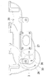
- the peripheral wall (33) of the running passage and the downstream peripheral wall (36) on the downstream side of the discharge passage are integrally formed with the exhaust manifold (39). It is not necessary to assemble the passage downstream peripheral wall (36) to the exhaust manifold (39), and the number of parts assembling steps is reduced.
- the invention according to claim 19 has the following effects in addition to the effects of any one of claims 1 to 18.
- ⁇ Effect> The PM concentration of the EGR gas can be increased.
- the exhaust gas diverter (2) is provided upstream of the exhaust turbine (41) of the supercharger (40)
- the exhaust gas is exhausted before the exhaust turbine (41) loses exhaust energy.
- the exhaust gas (3) can be passed through the gas shunt (2) to increase the exhaust gas (3) swirling speed in the exhaust gas swirl chamber (9), and the PM in the exhaust gas (3) is applied. Centrifugal force can be increased and the PM concentration of EGR gas (4) can be increased.
- the invention according to claim 20 has the following effects in addition to the effects of any one of claims 1 to 19. ⁇ Effect>
- the engine can be reduced in size. Since PM in exhaust gas (3) is captured, and PM is burned and removed to regenerate without using DPF, emission gas (5) is discharged to the atmosphere, so DPF can be eliminated, The engine can be reduced in size.
- ⁇ Effect> The manufacturing cost of the engine can be reduced. DPF can be eliminated, PM incinerators such as burners and heaters necessary for regeneration of DPF, and post-injection using a common rail are not necessary, and the manufacturing cost of the engine can be reduced.
- the invention according to claim 21 has the following effects in addition to the effects of any one of claims 1 to 20.
- the exhaust treatment device can be configured compactly.
- a circuit housing case (57) is provided at the end of the exhaust flow divider (2), and a booster circuit (58) is housed in the circuit housing case (57), and the booster circuit (58). Since the voltage boosted in step 1 is applied to the electrodes (12) and (13) of the exhaust shunt (2), the exhaust shunt (2) and the circuit housing case (57) can be configured integrally.
- the exhaust treatment device can be configured compactly.
- the invention according to claim 22 has the following effect in addition to the effect of invention of claim 21.
- ⁇ Effect> It is not necessary to route a high voltage cable or the like outside the exhaust treatment device.
- a conductor (59) electrically connected to the booster circuit (58) is passed through the end wall (60) of the exhaust shunt (2), and the voltage is boosted by the booster circuit (58) through this conductor (59). Since the voltage is applied to the electrodes (12) and (13) of the exhaust shunt (2), a high voltage cable or the like for applying a high voltage from the booster circuit (58) to the electrodes (12) and (13) is provided. There is no need to route outside the exhaust treatment system.
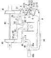
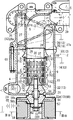
- FIG. 1 is a schematic diagram of an exhaust treatment device for a diesel engine according to a first embodiment of the present invention. It is a longitudinal cross-sectional view of the exhaust gas shunt of the exhaust treatment device shown in FIG.
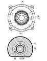
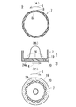
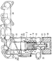
- FIGS. 3A and 3B are diagrams for explaining the exhaust gas diverter shown in FIG. 2, in which FIG. 3A is a plan view of the central cylinder and the exhaust gas swirl chamber peripheral wall, and FIG. . 4A and 4B are diagrams for explaining a central cylinder used in the exhaust gas flow divider shown in FIG. 2, FIG. 4A is a cross-sectional plan view, FIG. 4B is a longitudinal sectional view of the central cylinder terminal portion, and FIG. FIG. FIG.
- FIG. 3 is a side view of an exhaust manifold provided with the exhaust gas diverter of FIG. 2.
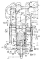
- FIG. 3 is a plan view of an exhaust manifold provided with the exhaust gas diverter of FIG. 2. It is a longitudinal cross-sectional view of the exhaust gas shunt of the exhaust processing apparatus of the diesel engine which concerns on 2nd Embodiment of this invention.
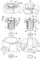
- 8A and 8B are diagrams illustrating the exhaust gas flow divider shown in FIG. 7, in which FIG. 8A is an exploded perspective view seen from diagonally above, and FIG. 8B is a divided perspective view seen diagonally from below.
- FIGS. 7 to 8 are diagrams for explaining an exhaust treatment device for a diesel engine according to the second embodiment.
- the processing apparatus will be described.
- the outline of the exhaust treatment apparatus of the first embodiment is as follows. As shown in FIG. 1, an exhaust gas diverter (2) is provided in the exhaust path (1), the PM in the exhaust gas (3) is unevenly distributed by the exhaust flow diverter (2), and the exhaust gas (3) is unevenly distributed.
- the EGR gas (4) containing PM is divided into the remaining release gas (5), the EGR gas (4) is returned to the combustion chamber (42), and the release gas (5) is released to the atmosphere side.
- the exhaust path (1) is configured by sequentially connecting an exhaust port (43), an exhaust manifold (39), an exhaust gas diverter (2), and an exhaust turbine (41) of a supercharger (40).
- the EGR gas (4) is returned to the intake passage (47) through the EGR cooler (44), the EGR valve chamber (45), and the check valve chamber (46) in this order.
- the intake path (47) is configured by connecting a compressor (48), a supercharge pipe (56), an intake manifold (49), and an intake port (50) of the supercharger (40) in this order.
- the EGR valve (45a) in the EGR valve chamber (45) is driven to open and close by a valve actuator (45b), and is opened and closed according to the engine speed and engine load, and the opening degree is adjusted.
- the configuration of the exhaust gas shunt is as follows. As shown in FIG. 2, a central cylinder (7) is arranged at the center of the exhaust gas flow divider (2), and a plurality of discharge gas entry holes (8) are provided on the peripheral wall of the central cylinder (7). An exhaust gas swirl chamber (9) is provided around the cylinder (7), and electrodes (12) and (13) having different polarities are provided in the exhaust gas diverter (2). Between these electrodes (12) and (13), By this corona discharge, the PM in the exhaust gas (3) is charged to a predetermined polarity.
- the exhaust gas swirl chamber peripheral wall (14) surrounding the exhaust gas swirl chamber (9) from the surroundings is made into an electrode (13) having a polarity opposite to that of the charged PM, and the exhaust gas swirl chamber (9) in the exhaust gas (3) swirling
- the charged PM is unevenly distributed near the exhaust gas swirl chamber peripheral wall (14) by centrifugal force and electrostatic force, and the exhaust gas (3) containing the unevenly distributed PM is used as the EGR gas (4) in the exhaust gas swirl chamber end portion (15).
- the exhaust gas (3) near the central cylinder (7) is split into the central cylinder (7) from the discharge gas inlet hole (8) as the discharge gas (5).
- the central tube (7) is a negative electrode (12) having the same polarity as PM.
- the central cylinder (7) has a cylindrical shape, and the discharge gas entry holes (8) are arranged in a line at a predetermined distance from the bus bar of the central cylinder (7). A plurality of rows are arranged at predetermined intervals in the circumferential direction of (7). As shown in FIG. 4 (A), an acute angle portion (8a) is provided at the opening edge of the released gas entry hole (8).
- the direction of the discharge gas entry hole (8) from the exhaust gas swirl chamber (9) side into the central cylinder (7) is set to be opposite to the swirl direction of the exhaust gas (3).
- the acute angle portion (8a) is a portion having an acute angle on the cross section of the central axis (7) perpendicular to the central axis.
- the central cylinder (7) is an electrode (12) having the same polarity as the charged PM, between the exhaust gas swirl chamber peripheral wall (14) serving as an electrode (13) having a polarity different from that of the charged PM, Corona discharge occurs, and the exhaust particulates can be charged efficiently in the exhaust gas swirl chamber (9).
- the central cylinder (7) is an electrode (12) having the same polarity as that of the charged PM, and the outer periphery of the central cylinder (7) is directed to the exhaust gas swirl chamber peripheral wall (14).
- a protruding discharge protrusion (6) is formed.
- the discharge protrusion (6) is a negative electrode (12) having the same polarity as the charged PM.
- the discharge protrusion (6) is integrally formed with the central tube (7).
- a plurality of rows of discharge protrusions (6) arranged along the circumferential direction of the outer periphery of the center tube (7) are arranged in the axial direction of the center tube (7). It is arranged.
- the row of discharge protrusions (6) arranged along the circumferential direction of the outer periphery of the center tube (7) is formed in a sawtooth shape.
- the discharge protrusions (6) are arranged at the exhaust gas swirl chamber start end (10), adjacent to the most upstream discharge gas inlet holes (8) and adjacent to the three rows. Yes. As shown in FIG.
- the discharge protrusions (6) are arranged in the axial direction. It arrange
- This discharge projection (6) is located between adjacent discharge gas entry holes (8) and (8).
- an exhaust gas deflection guide wall (18) is disposed upstream of the discharge projection (6), and the exhaust gas (3) toward the discharge projection (6) is sent to the exhaust gas deflection guide wall (18). ) To the exhaust gas swirl chamber peripheral wall (14) side around the discharge projection (6).
- the outer periphery of the exhaust gas deflection guide wall (18) has a curved surface shape in which the shape of the frustoconical circumferential surface, which gradually increases in diameter toward the downstream, is bent inward.
- a center tube end wall (20) is provided at the center tube end portion (19) surrounded by the exhaust gas swirl chamber end portion (15), and is adjacent to the exhaust gas swirl chamber end portion (15).
- the EGR gas swirl chamber (21) is provided, the EGR gas swirl chamber (21) is surrounded by the EGR gas swirl chamber peripheral wall (22), the EGR gas outlet (23) is provided, and the central cylinder end wall (20) is vented.
- a hole (24) is formed, and the gas component (25) of the EGR gas (4) overflowing from the center of the EGR gas swirl chamber (21) is discharged from the gas vent hole (24) as a discharge gas (5). It flows in.
- the EGR gas swirl chamber peripheral wall (22) and the EGR gas swirl chamber end wall (22a) are positive electrodes (13) having a polarity different from that of the charged PM.
- the central cylinder end wall (20) is a negative electrode (12) having the same polarity as the charged PM.
- the central cylinder end wall (20) is integrally formed with the peripheral wall of the central cylinder (7).
- an acute angle portion (24a) is provided at the opening edge of the gas vent hole (24), and as shown in FIGS. 4 (B) and (C), the center of the EGR gas swirl chamber (21) is provided.
- the direction of the gas vent hole (24) from the part side toward the inside of the central cylinder (7) is set to be opposite to the turning direction of the EGR gas (4).
- the acute angle portion (24a) is a portion having an acute angle on the cross-sectional view including the central axis of the gas vent hole (24) parallel to the central axis of the central cylinder (7). is there. As shown in FIG.
- the center tube (7) is arranged in the vertical direction, and the center tube end wall (20) is arranged at the lower end of the center tube (7), as shown in FIG. 4 (B).
- the gas vent hole (24) is inclined downward from the center tube (7) toward the EGR gas swirl chamber (21), and the PM accumulated in the center tube (7) is self-weighted when the engine is stopped. Then, the gas flows out from the vent hole (24) to the EGR gas swirl chamber (21).
- an exhaust gas swirl runway passage (26) is provided upstream of the exhaust gas swirl chamber (9) along the spiral runaway guide wall (26a).
- a discharge gas discharge passage (27) is provided at the center of the exhaust gas diverter (2) surrounded by the exhaust gas swirl run-up passage (26), and the discharge of the discharge gas discharge passage (27) is provided.
- the passage inlet (28) communicates with the central tube outlet (30) at the central tube start end (29).
- the exhaust gas swirl chamber peripheral wall (14) and the run-up passage peripheral wall (33) are connected by mounting bolts (61).
- the discharge passage peripheral wall (27a) of the discharge gas discharge passage (27) is divided into a discharge passage inlet peripheral wall (35) and a discharge passage downstream peripheral wall (36) downstream of the discharge passage inlet peripheral wall (35).
- the discharge passage inlet peripheral wall (35) is interposed between the discharge passage downstream peripheral wall (36) and the central tube outlet peripheral wall (37).
- the discharge passage inlet peripheral wall (35) is formed of an electrical insulator, and the exhaust gas swirl chamber peripheral wall (14) and the run-up passage peripheral wall (33) serving as electrodes (13) of different polarities are discharged from the central tube (7).
- the passage downstream side peripheral wall (36) is electrically insulated.
- the discharge passage inlet peripheral wall (35) is made of alumina.
- the input terminal (52) to the discharge protrusion (6) is connected to the discharge protrusion (6) via the center tube (7).
- the input terminal (52) and the central cylinder (7) are electrically insulated from the end wall (22a) of the EGR gas swirl chamber by insulating spacers (53) (54) fitted to the input terminal (52). .
- the input terminal (52) to the negative electrode (12) such as the central tube (7) and the discharge protrusion (6) is connected to the negative output terminal (58a) of the booster circuit (58) via the conductive plate (62). It is connected.
- the positive output of the booster circuit (58) is grounded.
- reference numeral (55) denotes a battery
- (58b) denotes a plus input terminal of the booster circuit (58).
- An insulating tube (66) fitted to the input terminal (52) is disposed at the joint between the spacers (53) and (54), and between the input terminal (52) and the EGR gas swirl chamber end wall (22a). Discharge is prevented from occurring.
- the peripheral wall (33) of the runway, the peripheral wall (36) on the downstream side of the discharge passage, and the runway guide wall (26a) are integrally formed with the exhaust manifold (39). These are integrally cast products of cast iron.
- an exhaust gas diverter (2) is provided upstream of the exhaust turbine (41) of the supercharger (40). Further, the exhaust gas (3) is trapped, and the emitted gas (5) is discharged to the atmosphere without using the DPF, which is recovered by burning and removing the PM.
- a circuit housing case (57) is provided at the end of the exhaust flow divider (2), and a booster circuit (58) is housed in the circuit housing case (57).
- the voltage boosted by the booster circuit (58) is applied to the electrodes (12) and (13) of the exhaust shunt (2).
- a conductor (59) electrically connected to the booster circuit (58) is passed through the end wall (60) of the exhaust shunt (2), and the voltage is boosted by the booster circuit (58) through this conductor (59).
- a voltage is applied to the electrodes (12) and (13) of the exhaust gas shunt (2).
- the conductor (59) is an input terminal (52), and the input terminal (52) is electrically connected to the negative output terminal (58a) of the booster circuit (58) through the conductive plate (62).
- the circuit housing case (57) is annular, and the input terminal (52) and the conductive plate (62) are arranged at the center, the booster circuit (58) is housed in the surrounding case, and the conductive plate (62)
- the insulating spacer (54) fitted to the input terminal (52) is fixed by being sandwiched between a conductive washer (63) and electrically connected to the input terminal (52).
- An insulated air chamber (64) of the circuit housing case (57) is disposed above the booster circuit (58).
- the second embodiment of the present invention shown in FIGS. 7 to 8 differs from the first embodiment in the following points.
- An exhaust gas swirl guide vane (11) is provided at the exhaust gas swirl chamber start end (10), and this exhaust gas swirl guide vane (11) is used as an electrode (12) having the same polarity as the charged PM.
- Edge portions (16) and (17) are provided with acute angle portions (16a) and (17a). Therefore, the swirl speed of the exhaust gas (3) in the exhaust gas swirl chamber (9) can be increased by the rectifying action of the exhaust gas swirl guide vane (11), and the centrifugal force applied to the PM in the exhaust gas (3). The force can be increased and the PM concentration of the EGR gas (4) can be increased.
- corona discharge occurs between the exhaust gas swirl chamber peripheral wall (14) serving as the electrodes (13) of different polarities, and the exhaust particulates can be efficiently charged in the exhaust gas swirl chamber (9). Moreover, PM in exhaust gas (3) can be charged efficiently. The reason for this is presumed to be that the electric field is concentrated near the acute angle portions (16a) and (17a) and corona discharge is generated to efficiently charge the PM.
- An exhaust gas swirl guide vane (11) is provided at the start end (10) of the exhaust gas swirl chamber, and a peripheral wall (33) of the runway surrounding the exhaust gas swirl guide vane (11) and the exhaust gas swirl runway (26) from the surroundings.
- electrodes 12 and 13 having different polarities.
- the exhaust gas swirl guide vane (11) is a negative electrode (12), and the runway peripheral wall (33) is a positive electrode (13).
- An exhaust gas swirl chamber start end (10) is provided around the central cylinder outlet peripheral wall (37), and the exhaust gas swirl chamber peripheral wall (14) surrounds the exhaust gas swirl chamber start end (10) from the periphery. (31) and a swirl chamber downstream peripheral wall (32) downstream of the swirl chamber start end peripheral wall (31), and between the runway peripheral wall (33) and the swirl chamber downstream peripheral wall (32).
- the swirl chamber start end peripheral wall (31) is interposed between the two.
- the discharge passage peripheral wall (27a) of the discharge gas discharge passage (27) is divided into a discharge passage inlet peripheral wall (35) and a discharge passage downstream peripheral wall (36) downstream of the discharge passage inlet peripheral wall (35).
- the discharge passage inlet peripheral wall (35) is interposed between the discharge passage downstream peripheral wall (36) and the central tube outlet peripheral wall (37), and the swirl chamber start end peripheral wall (31), the discharge passage inlet peripheral wall (35), and these
- the cross-linking body (31a) connecting the two is integrally molded with an electrical insulator, and the exhaust gas swirl guide vane is placed against the central cylinder (7) serving as the electrode (12) having the same polarity as the exhaust gas swirl guide vane (11).
- the swirl chamber downstream peripheral wall (32), the run-up passage peripheral wall (33), and the discharge passage downstream peripheral wall (36), which are electrodes (13) having a polarity different from (11), are electrically insulated.
- this insulator also electrically insulates the EGR gas swirl chamber peripheral wall (22) and the EGR gas swirl chamber end wall (22a), which are electrodes (13) of different polarities, from the central tube (7).
- the insulator is made of alumina. Insulating parts can be assembled together.
- the bridged body (31a) was an upstream exhaust gas swirl guide vane (38) located upstream of the exhaust gas swirl guide vane (11). Therefore, the swirling speed of the exhaust gas (3) in the exhaust gas swirl chamber (9) can be increased by the rectifying action of the upstream exhaust gas swirl guide vane (38), and the PM in the exhaust gas (3) is applied. Centrifugal force can be increased and the PM concentration of EGR gas (4) can be increased.
- Other configurations and functions of the second embodiment are the same as those of the first embodiment. In FIGS. 7 to 8, the same elements as those of the first embodiment are denoted by the same reference numerals.
- the embodiment of the present invention is as described above, but the present invention is not limited to the above-described embodiment, and the PM may be charged to a positive polarity.
- the peripheral wall (33) of the run-up passage, the peripheral wall (36) on the downstream side of the discharge passage, and the run-up guide blade (26a) are negative electrodes having a polarity different from that of the charged PM.
Landscapes
- Engineering & Computer Science (AREA)
- Chemical & Material Sciences (AREA)
- Chemical Kinetics & Catalysis (AREA)
- Combustion & Propulsion (AREA)
- Mechanical Engineering (AREA)
- General Engineering & Computer Science (AREA)
- Health & Medical Sciences (AREA)
- Toxicology (AREA)
- Processes For Solid Components From Exhaust (AREA)
- Electrostatic Separation (AREA)
- Exhaust-Gas Circulating Devices (AREA)
- Separating Particles In Gases By Inertia (AREA)
Priority Applications (4)
| Application Number | Priority Date | Filing Date | Title |
|---|---|---|---|
| CN201080012932.8A CN102362049B (zh) | 2009-04-30 | 2010-03-12 | 柴油发动机的废气处理装置 |
| KR1020117018464A KR101672566B1 (ko) | 2009-04-30 | 2010-03-12 | 디젤 엔진의 배기처리장치 |
| EP10769565.2A EP2426325B1 (en) | 2009-04-30 | 2010-03-12 | Exhaust gas treatment device of a diesel engine |
| US13/255,951 US8793974B2 (en) | 2009-04-30 | 2010-03-12 | Exhaust gas treatment device of diesel engine |
Applications Claiming Priority (4)
| Application Number | Priority Date | Filing Date | Title |
|---|---|---|---|
| JP2009-110495 | 2009-04-30 | ||
| JP2009110495 | 2009-04-30 | ||
| JP2010-019932 | 2010-02-01 | ||
| JP2010019932A JP5351791B2 (ja) | 2009-04-30 | 2010-02-01 | ディーゼルエンジンの排気処理装置 |
Publications (1)
| Publication Number | Publication Date |
|---|---|
| WO2010125865A1 true WO2010125865A1 (ja) | 2010-11-04 |
Family
ID=43032018
Family Applications (1)
| Application Number | Title | Priority Date | Filing Date |
|---|---|---|---|
| PCT/JP2010/054216 Ceased WO2010125865A1 (ja) | 2009-04-30 | 2010-03-12 | 多気筒エンジン |
Country Status (6)
| Country | Link |
|---|---|
| US (1) | US8793974B2 (enExample) |
| EP (1) | EP2426325B1 (enExample) |
| JP (1) | JP5351791B2 (enExample) |
| KR (1) | KR101672566B1 (enExample) |
| CN (1) | CN102362049B (enExample) |
| WO (1) | WO2010125865A1 (enExample) |
Cited By (2)
| Publication number | Priority date | Publication date | Assignee | Title |
|---|---|---|---|---|
| JP2012062847A (ja) * | 2010-09-17 | 2012-03-29 | Kubota Corp | ディーゼルエンジンの排気処理装置 |
| CN116273513A (zh) * | 2023-02-28 | 2023-06-23 | 中国石油化工股份有限公司 | 一种旋风分离单体、分离装置、分离系统及使用方法 |
Families Citing this family (8)
| Publication number | Priority date | Publication date | Assignee | Title |
|---|---|---|---|---|
| US8627805B2 (en) * | 2010-03-27 | 2014-01-14 | Cummins Inc. | System and apparatus for controlling reverse flow in a fluid conduit |
| JP5806967B2 (ja) * | 2012-03-30 | 2015-11-10 | 株式会社クボタ | ディーゼルエンジンの排気処理装置 |
| EP3168450A1 (en) * | 2015-11-12 | 2017-05-17 | Winterthur Gas & Diesel Ltd. | Internal combustion engine, method for cleaning exhaust from an internal combustion engine and method for refitting an internal combustion engine |
| CN106499551B (zh) * | 2016-10-12 | 2017-07-28 | 同济大学 | 一种清洁的egr回路系统 |
| CN106988935B (zh) * | 2016-12-13 | 2019-08-20 | 中国第一汽车股份有限公司 | 一种egr废气净化冷却加压一体化装置 |
| CN107486335A (zh) * | 2017-02-07 | 2017-12-19 | 安徽鹰龙工业设计有限公司 | 一种增压循环吸附的静电除尘装置 |
| WO2018226382A1 (en) * | 2017-06-09 | 2018-12-13 | Achates Power, Inc. | Supercharger protection in an opposed-piston engine with egr |
| CN113117906B (zh) * | 2021-04-21 | 2022-01-04 | 西南石油大学 | 一种针对页岩锤磨钻屑粉尘的静电旋风复合分离装置 |
Citations (4)
| Publication number | Priority date | Publication date | Assignee | Title |
|---|---|---|---|---|
| JPH03207463A (ja) * | 1990-01-11 | 1991-09-10 | Mitsubishi Heavy Ind Ltd | ダスト分離装置 |
| JP2003106137A (ja) * | 2001-09-27 | 2003-04-09 | Komatsu Ltd | 内燃機関の排気ガス浄化装置 |
| JP2006346538A (ja) * | 2005-06-14 | 2006-12-28 | Pauretsuku:Kk | サイクロン式固気分離装置 |
| JP2007278194A (ja) | 2006-04-07 | 2007-10-25 | Hino Motors Ltd | 排気処理装置 |
Family Cites Families (12)
| Publication number | Priority date | Publication date | Assignee | Title |
|---|---|---|---|---|
| CA714367A (en) * | 1965-07-27 | Mitsubishi Denki Kabushiki Kaisha | Electrostatic dust collector | |
| SE389461B (sv) * | 1974-12-11 | 1976-11-08 | Fi Wes Maskinservice Ab | Ljuddempare for tryckluftsverktyg for samtidigt avskiljning av smorjolja fran tryckluften |
| DE3141156A1 (de) * | 1981-10-16 | 1983-04-28 | Robert Bosch Gmbh, 7000 Stuttgart | Verfahren und vorrichtung zum entfernen von festen bestandteilen und aerosolen, insbesondere von russbestandteilen aus dem abgas von brennkraftmaschinen |
| DE3424196A1 (de) * | 1984-02-11 | 1985-08-22 | Robert Bosch Gmbh, 7000 Stuttgart | Einrichtung zur entfernung von festkoerperteilen aus abgasen von brennkraftmaschinen |
| DE3500375A1 (de) * | 1985-01-08 | 1986-07-10 | Robert Bosch Gmbh, 7000 Stuttgart | Vorrichtung zum entfernen von festkoerperpartikeln, insbesondere russteilchen, aus dem abgas von brennkraftmaschinen |
| JPH0611374B2 (ja) * | 1988-09-05 | 1994-02-16 | 帝国ピストンリング株式会社 | 微粒子分離装置 |
| DE3841182A1 (de) * | 1988-12-07 | 1990-06-13 | Bosch Gmbh Robert | Einrichtung zum entfernen von festkoerperpartikeln, insbesondere russteilchen, aus dem abgas von brennkraftmaschinen |
| JP3207463B2 (ja) * | 1991-09-25 | 2001-09-10 | マツダ株式会社 | 車両のアンチスキッドブレーキ装置 |
| JPH05222915A (ja) * | 1992-02-10 | 1993-08-31 | Nippon Soken Inc | 内燃機関の排気ガス浄化装置 |
| JPH05277313A (ja) * | 1992-03-31 | 1993-10-26 | Teikoku Piston Ring Co Ltd | 微粒子分離装置 |
| JPH06141552A (ja) * | 1992-10-26 | 1994-05-20 | Kasuga Denki Kk | 高周波高圧電源の電力制御装置 |
| KR20010014570A (ko) * | 1999-04-23 | 2001-02-26 | 구자홍 | 싸이클론 집진장치의 압력손실 저감 장치 |
-
2010
- 2010-02-01 JP JP2010019932A patent/JP5351791B2/ja not_active Expired - Fee Related
- 2010-03-12 US US13/255,951 patent/US8793974B2/en not_active Expired - Fee Related
- 2010-03-12 WO PCT/JP2010/054216 patent/WO2010125865A1/ja not_active Ceased
- 2010-03-12 KR KR1020117018464A patent/KR101672566B1/ko not_active Expired - Fee Related
- 2010-03-12 CN CN201080012932.8A patent/CN102362049B/zh not_active Expired - Fee Related
- 2010-03-12 EP EP10769565.2A patent/EP2426325B1/en not_active Not-in-force
Patent Citations (4)
| Publication number | Priority date | Publication date | Assignee | Title |
|---|---|---|---|---|
| JPH03207463A (ja) * | 1990-01-11 | 1991-09-10 | Mitsubishi Heavy Ind Ltd | ダスト分離装置 |
| JP2003106137A (ja) * | 2001-09-27 | 2003-04-09 | Komatsu Ltd | 内燃機関の排気ガス浄化装置 |
| JP2006346538A (ja) * | 2005-06-14 | 2006-12-28 | Pauretsuku:Kk | サイクロン式固気分離装置 |
| JP2007278194A (ja) | 2006-04-07 | 2007-10-25 | Hino Motors Ltd | 排気処理装置 |
Cited By (2)
| Publication number | Priority date | Publication date | Assignee | Title |
|---|---|---|---|---|
| JP2012062847A (ja) * | 2010-09-17 | 2012-03-29 | Kubota Corp | ディーゼルエンジンの排気処理装置 |
| CN116273513A (zh) * | 2023-02-28 | 2023-06-23 | 中国石油化工股份有限公司 | 一种旋风分离单体、分离装置、分离系统及使用方法 |
Also Published As
| Publication number | Publication date |
|---|---|
| CN102362049A (zh) | 2012-02-22 |
| KR101672566B1 (ko) | 2016-11-03 |
| JP5351791B2 (ja) | 2013-11-27 |
| US8793974B2 (en) | 2014-08-05 |
| US20120000186A1 (en) | 2012-01-05 |
| EP2426325A4 (en) | 2014-10-15 |
| KR20120003431A (ko) | 2012-01-10 |
| EP2426325B1 (en) | 2017-08-02 |
| EP2426325A1 (en) | 2012-03-07 |
| CN102362049B (zh) | 2014-06-04 |
| JP2010276012A (ja) | 2010-12-09 |
Similar Documents
| Publication | Publication Date | Title |
|---|---|---|
| JP5351791B2 (ja) | ディーゼルエンジンの排気処理装置 | |
| JP2010276012A5 (enExample) | ||
| EP1212141B8 (fr) | Dispositif de traitement des gaz d'echappement d'un moteur a combustion interne | |
| US7356987B2 (en) | Exhaust gas recirculation system having an electrostatic precipitator | |
| ATE188015T1 (de) | Vorrichtung zum reinigen von abgasen aus verbrennungskraftmaschinen | |
| JP5427739B2 (ja) | ディーゼルエンジンの排気処理装置 | |
| KR101505455B1 (ko) | 차량용 매연저감장치 | |
| JP5806967B2 (ja) | ディーゼルエンジンの排気処理装置 | |
| CN207526555U (zh) | 一种气体颗粒捕集装置 | |
| US20060021503A1 (en) | Electrostatic precipitator particulate trap with impingement filtering element | |
| US20030121251A1 (en) | System for agglomerating exhausted particulate matter | |
| US9061290B1 (en) | Intake or exhaust gas particle removal apparatus | |
| RU2105164C1 (ru) | Устройство для очистки от сажи отработавших газов и уменьшения шума двигателя внутреннего сгорания | |
| CN111344548A (zh) | 用于内燃发动机的颗粒传感器 | |
| RU2714985C1 (ru) | Устройство для очистки и рециркуляции выхлопных газов | |
| CN212732580U (zh) | 一种电极绝缘外置式静电吸附颗粒捕集器 | |
| CN212744118U (zh) | 一种免维护柴油颗粒电捕集器 | |
| US9849416B2 (en) | Method for cleaning exhaust filter system | |
| KR101339085B1 (ko) | 절연유지가 용이한 하전방식의 매연여과장치 | |
| CN212744120U (zh) | 一种静电吸附颗粒捕集器 | |
| JP5531978B2 (ja) | 内燃機関の排気処理装置 | |
| JPS59101521A (ja) | デイ−ゼル機関の排気ガス処理装置 | |
| KR102688556B1 (ko) | 하전부를 포함하는 선박용 디젤 엔진의 배기가스 여과 장치 | |
| KR100387477B1 (ko) | 디젤 엔진용 유해물질 저감장치 | |
| KR200177146Y1 (ko) | 전기저항을 이용한 디젤엔진 매연제거장치 |
Legal Events
| Date | Code | Title | Description |
|---|---|---|---|
| WWE | Wipo information: entry into national phase |
Ref document number: 201080012932.8 Country of ref document: CN |
|
| 121 | Ep: the epo has been informed by wipo that ep was designated in this application |
Ref document number: 10769565 Country of ref document: EP Kind code of ref document: A1 |
|
| ENP | Entry into the national phase |
Ref document number: 20117018464 Country of ref document: KR Kind code of ref document: A |
|
| REEP | Request for entry into the european phase |
Ref document number: 2010769565 Country of ref document: EP |
|
| WWE | Wipo information: entry into national phase |
Ref document number: 2010769565 Country of ref document: EP |
|
| WWE | Wipo information: entry into national phase |
Ref document number: 13255951 Country of ref document: US |
|
| WWE | Wipo information: entry into national phase |
Ref document number: 6649/CHENP/2011 Country of ref document: IN |
|
| NENP | Non-entry into the national phase |
Ref country code: DE |