WO2010125844A1 - 変位測定装置及び変位測定方法 - Google Patents
変位測定装置及び変位測定方法 Download PDFInfo
- Publication number
- WO2010125844A1 WO2010125844A1 PCT/JP2010/052599 JP2010052599W WO2010125844A1 WO 2010125844 A1 WO2010125844 A1 WO 2010125844A1 JP 2010052599 W JP2010052599 W JP 2010052599W WO 2010125844 A1 WO2010125844 A1 WO 2010125844A1
- Authority
- WO
- WIPO (PCT)
- Prior art keywords
- measured
- fine particles
- light
- displacement
- displacement measuring
- Prior art date
- Legal status (The legal status is an assumption and is not a legal conclusion. Google has not performed a legal analysis and makes no representation as to the accuracy of the status listed.)
- Ceased
Links
Images





Classifications
-
- G—PHYSICS
- G01—MEASURING; TESTING
- G01B—MEASURING LENGTH, THICKNESS OR SIMILAR LINEAR DIMENSIONS; MEASURING ANGLES; MEASURING AREAS; MEASURING IRREGULARITIES OF SURFACES OR CONTOURS
- G01B11/00—Measuring arrangements characterised by the use of optical techniques
- G01B11/14—Measuring arrangements characterised by the use of optical techniques for measuring distance or clearance between spaced objects or spaced apertures
-
- B—PERFORMING OPERATIONS; TRANSPORTING
- B82—NANOTECHNOLOGY
- B82Y—SPECIFIC USES OR APPLICATIONS OF NANOSTRUCTURES; MEASUREMENT OR ANALYSIS OF NANOSTRUCTURES; MANUFACTURE OR TREATMENT OF NANOSTRUCTURES
- B82Y15/00—Nanotechnology for interacting, sensing or actuating, e.g. quantum dots as markers in protein assays or molecular motors
Definitions
- the present invention relates to a displacement measuring apparatus and a displacement measuring method for measuring a displacement of a distance to an object to be measured.
- Patent Document 1 irradiates fine particles having a diameter of 8 ⁇ m with laser light, traps the fine particles by the light radiation pressure, and brings the fine particles closer to the object to be measured while modulating the intensity of the laser light.
- the position of the object to be measured is obtained from the change in the vibration state when the fine particles contact the object to be measured.
- the present inventors have succeeded in measuring the shape of the object to be measured on the order of several tens of nanometers.
- Patent Document 1 in order to measure the position and shape of the object to be measured, it is necessary to bring the fine particles trapped by the laser light into contact with the surface of the object to be measured as described above.
- the object to be measured has a fine shape with a high aspect ratio (for example, a fine groove with a width ⁇ 8 ⁇ m and a depth >> 8 ⁇ m)
- the fine particles are deep in the object to be measured (in the above example, the fine The bottom of the groove cannot be contacted.
- Patent Document 1 as described above, the position of the object to be measured is obtained from the change in the vibration state when the fine particles contact the object to be measured. In the calculation at this time, the change in the vibration state detected is detected. A predetermined process is performed to obtain the position of the object to be measured indirectly. That is, Patent Document 1 does not directly measure the actual position of the object to be measured against the scale.
- the present invention has been made in view of the above problems, and its purpose is to directly and accurately determine the position and shape of the measurement object even when the measurement object has a fine shape with a high aspect ratio. Displacement measuring apparatus and displacement measuring method that can be measured automatically.
- a displacement measuring device that measures the displacement of the distance to the object to be measured, A light irradiating means for irradiating a laser beam to light transmissive fine particles disposed at a predetermined distance from the surface of the object to be measured; Moving means for relatively moving the fine particles held in the optical standing field generated by the interference between the transmitted light of the fine particles and the reflected light from the measured object, with respect to the measured object; Detecting means for detecting a movement signal generated when the microparticles relatively move beyond the binding force due to the optical standing place; A calculation means for deriving a displacement of a distance to the object to be measured based on the movement signal; It is in having.
- an optical standing field is generated due to interference between the transmitted light of the fine particles and the reflected light from the object to be measured.
- the optical standing field can be a kind of scale.
- the displacement measuring apparatus of this configuration measures the displacement of the distance from the fine particle to the object to be measured using the fine particle restraining force due to the optical standing field and the fine particle trapping force due to the light radiation pressure. That is, the fine particles constrained in the optical standing field are moved using moving means for moving the fine particles relative to the object to be measured.
- the trapping force which is the force that moves the microparticles
- the binding force of the optical standing field which is the force that keeps the microparticles
- the microparticles move (jump)
- a movement signal is generated at that time.
- the displacement of the distance to the object to be measured can be derived.
- the light irradiation means is preferably a 633 nm iodine molecular absorption line wavelength-stabilized He—Ne laser device that defines an international standard length.
- the international standard length (scale) is based on the wavelength of the laser beam generated by the 633 nm iodine molecular absorption line wavelength stabilized He-Ne laser device. Therefore, the displacement measuring apparatus of this configuration employs the 633 nm iodine molecular absorption line wavelength stabilized He—Ne laser apparatus as the light irradiation means. As a result, the calculation means can directly calculate the displacement of the distance to the object to be measured without performing the conversion process based on the movement signal generated when the microparticle moves relatively beyond the restraint force due to the optical standing field. Can be derived.
- the moving means preferably moves the fine particles relative to each other by using a trapping force generated by a light radiation pressure of laser light applied to the fine particles by the light irradiation means.
- the laser light emitted from the light irradiating means generates a light standing field due to interference between the transmitted light and the reflected light, and at the same time, the trapping force due to the light radiation pressure acts on the fine particles. be able to. Then, using such a trapping force, the moving means can relatively move the fine particles.
- both the fine particle restraining force and the fine particle trapping force can be realized by the laser light emitted from the same light irradiation means, so that the device is simplified. be able to.
- the optical standing field is moved so as to follow the fine particles moved relative to the object to be measured by the moving means.
- the moving means follows the fine particles that move relative to the object to be measured, and the optical standing field as a scale moves together. Therefore, under any circumstance, a direct measurement of the displacement of the distance to the object to be measured in-situ can be performed.
- the moving means preferably moves the fine particles relative to the object to be measured in a three-dimensional manner.
- the moving means can relatively move the fine particles in three dimensions (that is, along the XYZ axes) with respect to the object to be measured. Therefore, even for a measurement object having a three-dimensional microstructure with a high aspect ratio, the position and shape of the measurement object can be accurately measured.
- the detection means is preferably a light detection means for detecting backscattered light as the movement signal.
- the light detecting means for detecting the backscattered light as the movement signal is adopted.
- This backscattered light can be easily analyzed from changes in the amount of received light. For this reason, if a light detection means is used, a highly accurate measurement result can be obtained simply.
- a light detection means can be comprised with the apparatus of an optical system similarly to an irradiation means, it can unify an irradiation system and a measurement system with an optical apparatus, and can simplify an apparatus structure.
- the predetermined distance is preferably set to 10 to 270 ⁇ m.
- the displacement measuring apparatus of this configuration it is possible to perform more reliable measurement by setting the predetermined distance from the fine particles to the surface of the object to be measured to 10 to 270 ⁇ m.
- a displacement measuring method for measuring a displacement of a distance to an object to be measured A light irradiation step of irradiating a laser beam to the light-transmitting fine particles arranged at a predetermined distance from the surface of the object to be measured; A moving step of moving the fine particles held in the optical standing field generated by interference between the transmitted light of the fine particles and the reflected light from the measured object with respect to the measured object; A detection step of detecting a movement signal generated when the microparticles move relatively beyond the binding force due to the optical standing place; A calculation step of deriving a displacement of the distance to the object to be measured based on the movement signal; It is to include.
- the displacement measuring method of this structure the same effect as the displacement measuring apparatus mentioned above is acquired.
- the displacement of the distance from the fine particle to the object to be measured is measured using the fine particle restraining force due to the optical standing field and the fine particle trapping force due to the light radiation pressure. That is, the fine particles constrained in the optical standing place are moved relative to the object to be measured.
- the trapping force which is the force that moves the microparticles
- the binding force of the optical standing field which is the force that keeps the microparticles
- the microparticles move (jump)
- the distance that is, the scale length of the scale
- the fine particles move can be changed by adjusting the wavelength of the laser beam. For example, by adjusting the wavelength of the laser light to the short wavelength side, the position and shape of the object to be measured can be measured more finely. As a result, it becomes easy to measure an object having a fine structure with a higher aspect ratio.
- the light irradiation step specifies a reference point where a trapping force for lifting the fine particles and a gravity of the fine particles are balanced.
- the fine particle is irradiated with the laser beam so that the trap force and the gravity of the fine particle are balanced, and the balanced position is specified as the reference point. Can do.
- the displacement from the reference point can be measured more accurately.
- FIG. 6 is a diagram for explaining measurement conditions and measurement results in “two-dimensional displacement measurement of free-form surface” performed as Example 2.
- FIG. FIG. 10 is a diagram for explaining measurement conditions and measurement results in “three-dimensional displacement measurement of a free-form surface” performed as Example 3. It is a figure explaining the measurement conditions and the measurement result by the confocal laser microscope performed for the comparison.
- FIG. 1A is a diagram for explaining the trapping force acting on the fine particles.
- FIG.1 (b) is a figure for demonstrating the optical standing field which restrains microparticles
- FIG. 1C is a diagram for explaining the intensity distribution on the z-axis of the reflected light in the fine particles.
- the optical standing is caused by interference between the transmitted light of the fine particles and the reflected light from the object to be measured.
- a field is generated.
- the optical standing field is a periodic light energy distribution formed between the fine particles and the object to be measured.
- the reflected light from the object to be measured is transmitted through the fine particles.
- the interval of intensity of reflected light in air is different from the interval of intensity of reflected light in fine particles. This is because the refractive index of light in air is different from the refractive index of light of fine particles.
- the displacement of the distance from the fine particle to the object to be measured is measured using the fine particle restraining force due to the optical standing field and the fine particle trapping force due to the light radiation pressure. is doing. This measurement will be specifically described with reference to FIG.
- FIG. 2 is a schematic diagram showing a state in which the fine particles are moved relative to the object to be measured, and the displacement of the distance to the object to be measured is measured.
- FIG. 2A shows a case where fine particles (laser spots) are moved in the proximity direction with respect to a flat object to be measured.
- (1) shows a state in which the restraining force (F stand ) due to the light standing field is sufficiently larger than the trapping force (F trap ) due to the light radiation pressure. At this time, the fine particles are restrained in the vicinity of the position where the light energy distribution in the optical standing field becomes maximum.
- FIG. 2B shows a case where the fine particles are moved laterally with respect to the object to be measured having an inclined surface.
- (1) shows a state in which the restraining force (F stand ) due to the light standing field is sufficiently larger than the trapping force (F trap ) due to the light radiation pressure.
- the fine particles are restrained in the vicinity of the position where the light energy distribution in the optical standing field becomes maximum.
- the fine particles are shifted in a direction away from the inclined surface due to binding force. Since the horizontal height position of the laser spot is unchanged, the trapping force acting in the proximity direction gradually increases.
- the fine particles move (jump) toward the proximity side by the half period ( ⁇ / 2) of the optical standing field.
- the trapping force and the gravity of the fine particles are balanced so that the fine particles are balanced.
- the laser beam is irradiated and a balanced position is specified as a reference point.
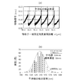
- FIG. 3 is a graph showing the result of verifying the periodicity of the optical standing field.
- FIG. 3A shows a movement signal (probe signal) detected when the fine particles are moved relative to the object to be measured in the optical standing field. This movement signal can be obtained from the change in the amount of received backscattered light of the fine particles.
- FIG. 3B shows the distribution of the periodicity (interference fringes) of the detected optical standing field. From the graphs of FIGS. 3 (a) and 3 (b), it was confirmed that the periodicity (average 534 nm) of the detected optical standing field was in good agreement with the half wavelength (532 nm) of the laser light.
- the periodicity of the optical standing field is used as a kind of scale. Specifically, when the fine particles are moved relative to the object to be measured, it is detected as a movement signal that the fine particles have moved (jumped) in the optical standing field by a half cycle. The movement signal is detected as a change in the amount of received backscattered light of the fine particles, as will be described later. Thereby, the displacement of the distance to the object to be measured can be derived very accurately (to the nanometer order) in a non-contact state. For this reason, even if the object to be measured has a fine shape with a high aspect ratio, its position and shape can be obtained with high accuracy.
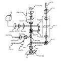
- FIG. 4 is a schematic diagram of the displacement measuring apparatus 100 of the present invention.
- the displacement measuring apparatus 100 includes a light irradiating means 10, a moving means 20, a detecting means 30, and a calculating means 40 as its basic configuration. Further, the displacement measuring apparatus 100 is constructed in combination with an optical microscope. In this case, the optical microscope also functions as the moving means 20. Therefore, in the following description, an optical microscope may be indicated by reference numeral 20.
- the light irradiation means 10 is a device that irradiates the light transmissive fine particles 50 with laser light.
- 8 ⁇ m silica spheres are used as the fine particles 50, and these are arranged 10 to 270 ⁇ m apart from the surface of the object S to be measured.
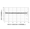
- the reason why the fine particles 50 are arranged at such a separation distance is that if the separation distance is less than 10 ⁇ m, the intensity of the reflected light from the object to be measured S is large, so that the binding force of the fine particles 50 becomes large, and accordingly the trapping force is increased. This is because the force exceeding the restraining force also increases, and the probability that the half cycle (interference fringes) is doubled (that is, ⁇ jump) increases.
- the separation distance exceeds 270 ⁇ m, the contrast of the periodicity (interference fringes) of the optical standing field becomes weak, and the interval at which the fine particles 50 fluctuate varies.
- a graph showing the relationship between the separation distance from the fine particles 50 to the object S to be measured and the fluctuation interval of the fine particles 50 is shown in FIG.
- the light irradiation means 10 for example, a CW laser that emits continuous light is used.
- the wavelength of the laser beam can be set to an arbitrary value. In the present embodiment, the wavelength ⁇ of the laser light is 1064 nm. However, adjustment means (not shown) may be provided in the light irradiation means 10 to change the wavelength of the laser light.
- the distance (that is, the length of the scale) on which the fine particles 50 move (jump) can be changed.
- the wavelength of the laser light to the short wavelength side
- the position and shape of the DUT S can be measured more finely.
- measurement of the object S having a finer structure with a higher aspect ratio becomes easier.
- the calculation means 40 to be described later converts the displacement of the distance to the object to be measured S based on the movement signal generated when the fine particle 50 moves relative to the restraint force due to the optical standing field.
- the laser light emitted from the light irradiation means 10 passes through an acousto-optic polarizer (AOD) 11, and then passes through a laser-side relay lens system 12, a reflecting prism 13, and a harmonic separator 14, and the objective lens of the optical microscope 20. Incident at 20d.
- the objective lens 20d irradiates the laser beam converged on the fine particles 50. Then, the transmitted light of the fine particles 50 and the reflected light from the measurement object S interfere with each other, and an optical standing field is formed between the fine particles 50 and the measurement object S.
- the optical microscope 20 includes a CCD camera 20a, a microscope-side relay lens system 20b, a tube lens 20c, an objective lens 20d, a stage 20e, a light 20f, and a mirror 20g.
- the user of the displacement measuring apparatus 100 confirms the position of the trapped fine particle 50 with the CCD camera 20a, and then operates the optical microscope 20 as a moving means to transmit the transmitted light of the fine particle 50 and the reflected light from the object S to be measured.
- the fine particles 50 held in the optical standing field generated by the interference with the object S are moved relative to the object S to be measured.
- the stage 20e of the optical microscope 20 on which the object to be measured S is placed is moved relative to the fine particles in three dimensions (that is, along the XYZ axes).
- the position and shape of the to-be-measured object S can be measured with high accuracy.
- the objective lens 20d itself may be configured to be movable. In these cases, along with the movement of the fine particles 50 trapped by the laser light irradiation from the objective lens 20d, the standing field as a scale also moves. Thus, in the present embodiment, it is possible to directly measure the displacement of the distance to the measurement object S in-situ.
- the detection means 30 includes a detection laser 30a, a collimator lens 30b, a first half prism 30c, a half mirror 30d, a second half prism 30e, a first mirror 30f, a second mirror 30g, an interference filter 30h, a lens 30i, and light detection.
- Device (PD) 30j The detection means 30 detects a movement signal generated when the fine particles 50 move relative to each other beyond the binding force due to the light standing field.
- the detection result is sent to the calculation means 40 and analyzed.
- the calculating means 40 derives the displacement of the distance to the object to be measured S based on the movement signal (the amount of received backscattered light) detected by the detecting means 30. For example, the calculation means 40 analyzes the displacement of the distance from the fine particle 50 to the measurement object S from the change in the amount of received backscattered light incident on the photodetector (PD) 30j. If such an analysis method is used, a highly accurate measurement result can be easily obtained.
- the computing means 40 can be composed of a general-purpose personal computer, for example.
- FIG. 6 is a diagram for explaining measurement conditions and measurement results in “planar displacement measurement” performed as Example 1.
- a silicon wafer is placed on the stage 20e of the optical microscope, and fine particles 50 serving as a probe are disposed here.
- the fine particles 50 are irradiated with laser light from the irradiation means 10, and the fine particles constrained in the optical standing field are irradiated with light.
- Relative movement was performed using the trapping force due to radiation pressure.
- the measurement conditions are such that the distance (scanning height) between the fine particles 50 and the surface of the silicon wafer is 40 ⁇ m or more, the moving direction is the X-axis direction, and the moving speed (scanning speed) is 5.6 ⁇ m. / S, and the moving distance was 1000 ⁇ m.
- FIG. 7 is a diagram for explaining measurement conditions and measurement results in “two-dimensional displacement measurement of a free-form surface” performed as Example 2.
- a silicon sphere was selected as the object to be measured S, and the two-dimensional microstructure of the free-form surface of this silicon sphere was obtained by displacement measurement using the displacement measuring apparatus 100 of the present invention.
- the diameter of the silicon sphere to be measured is 1 mm.
- the measurement condition is that the range covering the top of the silicon sphere ( ⁇ 200 ⁇ m to 200 ⁇ m in the X-axis direction) is the measurement range, and the distance (scanning height) between the fine particles 50 and the surface of the silicon sphere.
- the relative movement speed (scanning speed) of the fine particles 50 was 5.6 ⁇ m / s.
- the movement signal shown in the graph of (b) was detected as backscattering from the fine particles 50. When this was plotted as a displacement in the Z-axis direction with respect to the X-axis, a graph (c) was obtained.
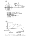
- FIG. 8 is a diagram for explaining measurement conditions and measurement results in “three-dimensional displacement measurement of a free-form surface” performed as Example 3.
- a micro plano-convex lens was selected as the object to be measured S, and the three-dimensional microstructure of the free-form surface of the micro plano-convex lens was obtained by displacement measurement using the displacement measuring apparatus 100 of the present invention.
- the micro plano-convex lens to be measured has a shape in which a disk-shaped member having a convex surface on the upper surface of the cylindrical member is integrated.
- the material of the micro plano-convex lens is LaSFN9 manufactured by Schott, Germany, and the diameter is 2 mm.
- the measurement conditions are a range covering the top of the micro plano-convex lens when viewed from above (1000 ⁇ m in the X-axis direction and 1000 ⁇ m in the Y-axis direction), a measurement interval of 100 ⁇ m, and a fine particle 50
- the distance (scanning height) between the microplano-convex lens and the surface of the micro plano-convex lens was 10 ⁇ m, and the relative movement speed (scanning speed) of the fine particles 50 was 5.6 ⁇ m / s.
- a graph (b) was obtained.
- the radius of curvature was calculated from the data fitting to be 2692 ⁇ m.
- FIG. 9 is a diagram for explaining measurement conditions and measurement results with a confocal laser microscope.
- the measurement conditions of this comparative test are as follows: the range covering the entire micro plano-convex lens as viewed from above (2200 ⁇ m in the X-axis direction and 2000 ⁇ m in the Y-axis direction) is the measurement range, and the measurement interval is 10 ⁇ m The number of measurement points was 44421.
- a graph (b) was obtained.
- the radius of curvature at the center line was calculated to be 2600 ⁇ m.
- the measurement result (curvature radius: 2692 ⁇ m) according to the present example was close to the measurement result (curvature radius: 2600 ⁇ m) obtained by the confocal laser microscope performed for comparison.
- the three-dimensional displacement measurement of the free-form surface can be performed with high accuracy.
- the displacement measuring apparatus and the displacement measuring method of the present invention can be suitably used in an ultra-high precision three-dimensional coordinate measuring machine (Nano-CMM) that evaluates the three-dimensional shape of an object without contact.
- Nano-CMM ultra-high precision three-dimensional coordinate measuring machine
Landscapes
- Physics & Mathematics (AREA)
- General Physics & Mathematics (AREA)
- Length Measuring Devices By Optical Means (AREA)
Abstract
Description
被測定物までの距離の変位を測定する変位測定装置であって、
前記被測定物の表面から所定距離に配置した光透過性の微粒子にレーザ光を照射する光照射手段と、
前記微粒子の透過光と前記被測定物からの反射光との干渉により生成した光定在場の中に保持された前記微粒子を前記被測定物に対して相対移動させる移動手段と、
前記微粒子が前記光定在場による拘束力を超えて相対移動したときに発生する移動信号を検知する検知手段と、
前記移動信号に基づいて、前記被測定物までの距離の変位を導出する演算手段と、
を備えたことにある。
そこで、本構成の変位測定装置では、光定在場による微粒子の拘束力と光放射圧による微粒子のトラップ力とを利用して、微粒子から被測定物までの距離の変位を測定している。すなわち、微粒子を被測定物に対して相対移動させる移動手段を用いて、光定在場中に拘束されている微粒子を移動させる。ここで、微粒子を移動させる力であるトラップ力が、微粒子を留まらせる力である光定在場の拘束力を超えて、微粒子が移動(ジャンプ)すると、その際に移動信号が発生する。この移動信号を検知手段により検知することで、被測定物までの距離の変位を導出することができる。このような測定は、微粒子を被測定物に対して非接触状態のまま行うことができる。従って、被測定物が高アスペクト比の微細形状を有する場合であっても、当該被測定物の位置や形状を精度よく測定することが可能となる。
また、微粒子が光定在場中で拘束される位置は、レーザ光の半波長(z=λ/2)ごとに存在している。このため、微粒子の移動(ジャンプ)は、レーザ光の半波長(z=λ/2)単位で行われる。従って、本構成の変位測定装置では、レーザ光の波長が明らかであれば、微粒子の移動(ジャンプ)により、被測定物までの距離がどれだけ変位したかを極めて正確に求めることができる。そして、微粒子を被測定物に対して相対移動させることで、被測定物の位置や形状を精度よく測定することができる。しかも、このような測定手法は、被測定物までの距離の変位を、光定在場の周期性を利用して、その場(in-situ)で直接的に測定するものであるから、実際のサイズを反映した極めて信頼性が高い測定結果となる。
前記レーザ光の波長を調整する調整手段を備えることが好ましい。
前記光照射手段は、国際標準長さを規定する633nmヨウ素分子吸収線波長安定化He-Neレーザ装置であることが好ましい。
前記移動手段は、前記光照射手段が前記微粒子に照射するレーザ光の光放射圧によるトラップ力を利用して、前記微粒子を相対移動させることが好ましい。
前記移動手段が前記被測定物に対して相対移動させる前記微粒子に追随して、前記光定在場が移動するように構成してあることが好ましい。
前記移動手段は、前記被測定物に対して前記微粒子を三次元的に相対移動させることが好ましい。
前記検知手段は、前記移動信号として後方散乱光を検知する光検知手段であることが好ましい。
前記所定距離は、10~270μmに設定されていることが好ましい。
被測定物までの距離の変位を測定する変位測定方法であって、
前記被測定物の表面から所定距離に配置した光透過性の微粒子にレーザ光を照射する光照射工程と、
前記微粒子の透過光と前記被測定物からの反射光との干渉により生成した光定在場の中に保持された前記微粒子を前記被測定物に対して相対移動させる移動工程と、
前記微粒子が前記光定在場による拘束力を超えて相対移動したときに発生する移動信号を検知する検知工程と、
前記移動信号に基づいて、前記被測定物までの距離の変位を導出する演算工程と、
を包含することにある。
また、微粒子が光定在場中で拘束される位置は、レーザ光の半波長(z=λ/2)ごとに存在している。このため、微粒子の移動(ジャンプ)は、レーザ光の半波長(z=λ/2)単位で行われる。従って、本構成の変位測定方法では、レーザ光の波長が明らかであれば、微粒子の移動(ジャンプ)により、被測定物までの距離がどれだけ変位したかを極めて正確に求めることができる。そして、微粒子を被測定物に対して相対移動させることで、被測定物の位置や形状を精度よく測定することができる。しかも、このような測定手法は、被測定物までの距離の変位を、光定在場の周期性を利用して、その場(in-situ)で直接的に測定するものであるから、実際のサイズを反映した極めて信頼性が高い測定結果となる。
前記レーザ光の波長を調整する調整工程を包含することが好ましい。
前記光照射工程は、前記微粒子を持ち上げるトラップ力と前記微粒子の重力とが釣り合う基準点の特定を実行することが好ましい。
初めに、本発明の測定原理について、図1を参照して説明する。本発明では、被測定物までの距離の変位を測定するためのプローブとして、光透過性の微粒子(例えば、シリカ微粒子)を使用する。図1(a)は、微粒子に作用するトラップ力を説明するための図である。図1(b)は、微粒子を拘束する光定在場を説明するための図である。図1(c)は、微粒子内における反射光のz軸上の強度分布を説明するための図である。
図4は、本発明の変位測定装置100の概略図である。変位測定装置100は、その基本構成として、光照射手段10、移動手段20、検知手段30、及び演算手段40を備えている。また、変位測定装置100は、光学顕微鏡と組み合わせて構築され、この場合、光学顕微鏡が移動手段20の機能を兼ねている。従って、以下の説明では、光学顕微鏡を参照符号20で示す場合がある。
20 移動手段
30 検知手段
40 演算手段
50 微粒子
100 変位測定装置
S 被測定物
Claims (11)
- 被測定物までの距離の変位を測定する変位測定装置であって、
前記被測定物の表面から所定距離に配置した光透過性の微粒子にレーザ光を照射する光照射手段と、
前記微粒子の透過光と前記被測定物からの反射光との干渉により生成した光定在場の中に保持された前記微粒子を前記被測定物に対して相対移動させる移動手段と、
前記微粒子が前記光定在場による拘束力を超えて相対移動したときに発生する移動信号を検知する検知手段と、
前記移動信号に基づいて、前記被測定物までの距離の変位を導出する演算手段と、
を備えた変位測定装置。 - 前記レーザ光の波長を調整する調整手段を備えた請求項1に記載の変位測定装置。
- 前記光照射手段は、国際標準長さを規定する633nmヨウ素分子吸収線波長安定化He-Neレーザ装置である請求項1に記載の変位測定装置。
- 前記移動手段は、前記光照射手段が前記微粒子に照射するレーザ光の光放射圧によるトラップ力を利用して、前記微粒子を相対移動させる請求項1~3の何れか一項に記載の変位測定装置。
- 前記移動手段が前記被測定物に対して相対移動させる前記微粒子に追随して、前記光定在場が移動するように構成してある請求項1~4の何れか一項に記載の変位測定装置。
- 前記移動手段は、前記被測定物に対して前記微粒子を三次元的に相対移動させる請求項1~5の何れか一項に記載の変位測定装置。
- 前記検知手段は、前記移動信号として後方散乱光を検知する光検知手段である請求項1~6の何れか一項に記載の変位測定装置。
- 前記所定距離は、10~270μmに設定されている請求項1~7の何れか一項に記載の変位測定装置。
- 被測定物までの距離の変位を測定する変位測定方法であって、
前記被測定物の表面から所定距離に配置した光透過性の微粒子にレーザ光を照射する光照射工程と、
前記微粒子の透過光と前記被測定物からの反射光との干渉により生成した光定在場の中に保持された前記微粒子を前記被測定物に対して相対移動させる移動工程と、
前記微粒子が前記光定在場による拘束力を超えて相対移動したときに発生する移動信号を検知する検知工程と、
前記移動信号に基づいて、前記被測定物までの距離の変位を導出する演算工程と、
を包含する変位測定方法。 - 前記レーザ光の波長を調整する調整工程を包含する請求項9に記載の変位測定方法。
- 前記光照射工程は、前記微粒子を持ち上げるトラップ力と前記微粒子の重力とが釣り合う基準点の特定を実行する、請求項9又は請求項10に記載の変位測定方法。
Priority Applications (2)
| Application Number | Priority Date | Filing Date | Title |
|---|---|---|---|
| US13/266,782 US8804130B2 (en) | 2009-04-30 | 2010-02-22 | Displacement measuring device and displacement measuring method |
| JP2011511336A JP5172011B2 (ja) | 2009-04-30 | 2010-02-22 | 変位測定装置及び変位測定方法 |
Applications Claiming Priority (2)
| Application Number | Priority Date | Filing Date | Title |
|---|---|---|---|
| JP2009110246 | 2009-04-30 | ||
| JP2009-110246 | 2009-04-30 |
Publications (1)
| Publication Number | Publication Date |
|---|---|
| WO2010125844A1 true WO2010125844A1 (ja) | 2010-11-04 |
Family
ID=43031998
Family Applications (1)
| Application Number | Title | Priority Date | Filing Date |
|---|---|---|---|
| PCT/JP2010/052599 Ceased WO2010125844A1 (ja) | 2009-04-30 | 2010-02-22 | 変位測定装置及び変位測定方法 |
Country Status (3)
| Country | Link |
|---|---|
| US (1) | US8804130B2 (ja) |
| JP (1) | JP5172011B2 (ja) |
| WO (1) | WO2010125844A1 (ja) |
Cited By (1)
| Publication number | Priority date | Publication date | Assignee | Title |
|---|---|---|---|---|
| CN109974591A (zh) * | 2019-03-22 | 2019-07-05 | 上海理工大学 | 颗粒微小位移测量装置及测量细微颗粒产生位移的方法 |
Families Citing this family (4)
| Publication number | Priority date | Publication date | Assignee | Title |
|---|---|---|---|---|
| US8675269B2 (en) * | 2010-12-03 | 2014-03-18 | Rochester Institute Of Technology | Optical lift apparatuses and methods thereof |
| CN103791845B (zh) * | 2014-01-21 | 2016-06-22 | 山西大学 | 基于激光高阶横模的光学横向小位移的测量方法及装置 |
| US11781420B2 (en) | 2021-03-25 | 2023-10-10 | Chengdu University Of Technology | Displacement measuring device and speed measuring method of drilling traction robot |
| EP4293581B1 (en) * | 2022-06-14 | 2025-03-26 | Alpine Quantum Technologies GmbH | Single-sided standing wave for exciting trapped ions |
Citations (4)
| Publication number | Priority date | Publication date | Assignee | Title |
|---|---|---|---|---|
| JPH09304266A (ja) * | 1996-05-21 | 1997-11-28 | Nippon Telegr & Teleph Corp <Ntt> | 光放射圧による微粒子の保持方法および変位測定方法 |
| JP2003344402A (ja) * | 2002-05-30 | 2003-12-03 | Japan Science & Technology Corp | Dna−金属微粒子系の共振周波数解析方法および共振周波数解析システム |
| JP2004012244A (ja) * | 2002-06-05 | 2004-01-15 | Osaka Industrial Promotion Organization | 光放射圧によりトラップした微粒子プローブを用いた測定装置及び方法 |
| JP2005181085A (ja) * | 2003-12-19 | 2005-07-07 | Ricoh Co Ltd | 光トラッププローブ近接場光顕微鏡装置及び近接場光検出方法 |
Family Cites Families (3)
| Publication number | Priority date | Publication date | Assignee | Title |
|---|---|---|---|---|
| US7110118B2 (en) * | 2000-12-19 | 2006-09-19 | Trustees Of Boston University | Spectral imaging for vertical sectioning |
| DE10100247A1 (de) * | 2001-01-05 | 2002-07-11 | Leica Microsystems | Interferenzmikroskop und Verfahren zum Betrieb eines Interferenzmikroskops |
| DE102008009216A1 (de) * | 2008-02-13 | 2009-08-20 | Carl Zeiss Microimaging Gmbh | Vorrichtung und Verfahren zum räumlich hochauflösenden Abbilden einer Struktur einer Probe |
-
2010
- 2010-02-22 JP JP2011511336A patent/JP5172011B2/ja not_active Expired - Fee Related
- 2010-02-22 WO PCT/JP2010/052599 patent/WO2010125844A1/ja not_active Ceased
- 2010-02-22 US US13/266,782 patent/US8804130B2/en not_active Expired - Fee Related
Patent Citations (4)
| Publication number | Priority date | Publication date | Assignee | Title |
|---|---|---|---|---|
| JPH09304266A (ja) * | 1996-05-21 | 1997-11-28 | Nippon Telegr & Teleph Corp <Ntt> | 光放射圧による微粒子の保持方法および変位測定方法 |
| JP2003344402A (ja) * | 2002-05-30 | 2003-12-03 | Japan Science & Technology Corp | Dna−金属微粒子系の共振周波数解析方法および共振周波数解析システム |
| JP2004012244A (ja) * | 2002-06-05 | 2004-01-15 | Osaka Industrial Promotion Organization | 光放射圧によりトラップした微粒子プローブを用いた測定装置及び方法 |
| JP2005181085A (ja) * | 2003-12-19 | 2005-07-07 | Ricoh Co Ltd | 光トラッププローブ近接場光顕微鏡装置及び近接場光検出方法 |
Non-Patent Citations (1)
| Title |
|---|
| "Proceedings of the Meeting of Japan Society of Precision Engineering, 25 February 2009 (25.02.2009)", vol. 2009, article DAISUKE NAKAI ET AL.: "Laser Trapping Probe o Mochiita Chosado Kyori Scanning ni Kansuru Kenkyu (the 2nd report) -Teizaijochu ni Sonzai suru Probe Tokusei no Hyoka", pages: 459 - 460 * |
Cited By (1)
| Publication number | Priority date | Publication date | Assignee | Title |
|---|---|---|---|---|
| CN109974591A (zh) * | 2019-03-22 | 2019-07-05 | 上海理工大学 | 颗粒微小位移测量装置及测量细微颗粒产生位移的方法 |
Also Published As
| Publication number | Publication date |
|---|---|
| US20120068066A1 (en) | 2012-03-22 |
| JP5172011B2 (ja) | 2013-03-27 |
| JPWO2010125844A1 (ja) | 2012-10-25 |
| US8804130B2 (en) | 2014-08-12 |
Similar Documents
| Publication | Publication Date | Title |
|---|---|---|
| JP5172011B2 (ja) | 変位測定装置及び変位測定方法 | |
| US10261305B2 (en) | Three-dimensional focusing device and method for a microscope | |
| CN102589851B (zh) | 反射式共焦透镜焦距测量方法 | |
| Ishikawa et al. | Integrated micro-displacement sensor that measures tilting angle and linear movement of an external mirror | |
| JP2017525568A (ja) | 液体ジェットの位置を特定するための方法 | |
| JP2006250826A (ja) | 計測素子、加工装置および計測方法、屈折率の計測素子 | |
| CN205561770U (zh) | 透镜厚度检测装置 | |
| CN111623871A (zh) | 利用纳米微粒测量激光光场相对强度分布的方法和装置 | |
| CN102096133A (zh) | 可调纳米光栅及纳米光栅加速度计及其加工方法 | |
| Michihata et al. | Three-dimensional measurement of structures with smooth-steep-surfaces using autofluorescence confocal signal | |
| TWI431240B (zh) | 三維量測系統 | |
| CN105698692A (zh) | 透镜厚度检测装置 | |
| CN114001672A (zh) | 形状测量方法 | |
| JP2010096570A (ja) | 表面形状測定装置 | |
| JP2012002548A (ja) | 光波干渉測定装置 | |
| JP4884063B2 (ja) | 深さ測定装置 | |
| CN206557055U (zh) | 一种纳米激光粒度分布测定仪 | |
| CN103791840A (zh) | 一种测量微位移的简易装置 | |
| KR101068518B1 (ko) | 탐침 표면 검사기의 자동 어프로치 방법, 탐침 표면 검사기의 자동 어프로치 장치 및 이를 구비하는 탐침 현미경 | |
| JP5366112B2 (ja) | 内径測定装置 | |
| JP2007051916A (ja) | 質量測定装置および質量測定方法 | |
| JP2004012244A (ja) | 光放射圧によりトラップした微粒子プローブを用いた測定装置及び方法 | |
| TWI359258B (en) | A contact measurement probe with optical sensing f | |
| JP5221211B2 (ja) | 形状測定装置 | |
| US20180283845A1 (en) | Wavelength modulatable interferometer |
Legal Events
| Date | Code | Title | Description |
|---|---|---|---|
| 121 | Ep: the epo has been informed by wipo that ep was designated in this application |
Ref document number: 10769544 Country of ref document: EP Kind code of ref document: A1 |
|
| ENP | Entry into the national phase |
Ref document number: 2011511336 Country of ref document: JP Kind code of ref document: A |
|
| WWE | Wipo information: entry into national phase |
Ref document number: 13266782 Country of ref document: US |
|
| NENP | Non-entry into the national phase |
Ref country code: DE |
|
| 122 | Ep: pct application non-entry in european phase |
Ref document number: 10769544 Country of ref document: EP Kind code of ref document: A1 |