WO2010122983A1 - 非水電解液二次電池用電極板、非水電解液二次電池用電極板の製造方法、および非水電解液二次電池 - Google Patents
非水電解液二次電池用電極板、非水電解液二次電池用電極板の製造方法、および非水電解液二次電池 Download PDFInfo
- Publication number
- WO2010122983A1 WO2010122983A1 PCT/JP2010/056939 JP2010056939W WO2010122983A1 WO 2010122983 A1 WO2010122983 A1 WO 2010122983A1 JP 2010056939 W JP2010056939 W JP 2010056939W WO 2010122983 A1 WO2010122983 A1 WO 2010122983A1
- Authority
- WO
- WIPO (PCT)
- Prior art keywords
- active material
- electrode active
- material layer
- electrode plate
- metal oxide
- Prior art date
- Legal status (The legal status is an assumption and is not a legal conclusion. Google has not performed a legal analysis and makes no representation as to the accuracy of the status listed.)
- Ceased
Links
Images


Classifications
-
- H—ELECTRICITY
- H01—ELECTRIC ELEMENTS
- H01M—PROCESSES OR MEANS, e.g. BATTERIES, FOR THE DIRECT CONVERSION OF CHEMICAL ENERGY INTO ELECTRICAL ENERGY
- H01M10/00—Secondary cells; Manufacture thereof
- H01M10/05—Accumulators with non-aqueous electrolyte
- H01M10/052—Li-accumulators
-
- H—ELECTRICITY
- H01—ELECTRIC ELEMENTS
- H01M—PROCESSES OR MEANS, e.g. BATTERIES, FOR THE DIRECT CONVERSION OF CHEMICAL ENERGY INTO ELECTRICAL ENERGY
- H01M10/00—Secondary cells; Manufacture thereof
- H01M10/05—Accumulators with non-aqueous electrolyte
- H01M10/058—Construction or manufacture
-
- H—ELECTRICITY
- H01—ELECTRIC ELEMENTS
- H01M—PROCESSES OR MEANS, e.g. BATTERIES, FOR THE DIRECT CONVERSION OF CHEMICAL ENERGY INTO ELECTRICAL ENERGY
- H01M4/00—Electrodes
- H01M4/02—Electrodes composed of, or comprising, active material
- H01M4/13—Electrodes for accumulators with non-aqueous electrolyte, e.g. for lithium-accumulators; Processes of manufacture thereof
-
- H—ELECTRICITY
- H01—ELECTRIC ELEMENTS
- H01M—PROCESSES OR MEANS, e.g. BATTERIES, FOR THE DIRECT CONVERSION OF CHEMICAL ENERGY INTO ELECTRICAL ENERGY
- H01M4/00—Electrodes
- H01M4/02—Electrodes composed of, or comprising, active material
- H01M4/13—Electrodes for accumulators with non-aqueous electrolyte, e.g. for lithium-accumulators; Processes of manufacture thereof
- H01M4/139—Processes of manufacture
-
- H—ELECTRICITY
- H01—ELECTRIC ELEMENTS
- H01M—PROCESSES OR MEANS, e.g. BATTERIES, FOR THE DIRECT CONVERSION OF CHEMICAL ENERGY INTO ELECTRICAL ENERGY
- H01M4/00—Electrodes
- H01M4/02—Electrodes composed of, or comprising, active material
- H01M4/62—Selection of inactive substances as ingredients for active masses, e.g. binders, fillers
- H01M4/621—Binders
-
- H—ELECTRICITY
- H01—ELECTRIC ELEMENTS
- H01M—PROCESSES OR MEANS, e.g. BATTERIES, FOR THE DIRECT CONVERSION OF CHEMICAL ENERGY INTO ELECTRICAL ENERGY
- H01M4/00—Electrodes
- H01M4/02—Electrodes composed of, or comprising, active material
- H01M4/62—Selection of inactive substances as ingredients for active masses, e.g. binders, fillers
- H01M4/624—Electric conductive fillers
- H01M4/625—Carbon or graphite
-
- Y—GENERAL TAGGING OF NEW TECHNOLOGICAL DEVELOPMENTS; GENERAL TAGGING OF CROSS-SECTIONAL TECHNOLOGIES SPANNING OVER SEVERAL SECTIONS OF THE IPC; TECHNICAL SUBJECTS COVERED BY FORMER USPC CROSS-REFERENCE ART COLLECTIONS [XRACs] AND DIGESTS
- Y02—TECHNOLOGIES OR APPLICATIONS FOR MITIGATION OR ADAPTATION AGAINST CLIMATE CHANGE
- Y02E—REDUCTION OF GREENHOUSE GAS [GHG] EMISSIONS, RELATED TO ENERGY GENERATION, TRANSMISSION OR DISTRIBUTION
- Y02E60/00—Enabling technologies; Technologies with a potential or indirect contribution to GHG emissions mitigation
- Y02E60/10—Energy storage using batteries
Definitions
- the present invention relates to an electrode plate used for a nonaqueous electrolyte secondary battery such as a lithium ion secondary battery, a method for producing the electrode plate, and a nonaqueous electrolyte secondary battery.
- a non-aqueous electrolyte secondary battery represented by a lithium ion secondary battery has a high energy density and a high voltage, and has a memory effect during charging / discharging (when the battery is charged before it is completely discharged, Since there is no phenomenon in which the capacity decreases, it is used in various fields such as portable devices, notebook computers, and portable devices.
- the non-aqueous electrolyte secondary battery is generally composed of a positive electrode plate, a negative electrode plate, a separator, and a non-aqueous electrolyte solution.
- a positive electrode plate one having an electrode active material layer in which positive electrode active material particles are fixed on the surface of a current collector such as a metal foil is generally used.
- a negative electrode plate one having an electrode active material layer in which negative electrode active material particles are fixed to the surface of a current collector such as copper or aluminum is generally used.
- electrode material particles that are positive electrode active material particles or negative electrode active material particles, a resin binder, and a conductive material (however, the negative electrode active material particles have a conductive effect) If the electrode performance is sufficiently obtained even without a conductive material, the conductive material may be omitted), or, if necessary, use other materials in a solvent.
- a slurry-like electrode active material layer forming composition is prepared by kneading and / or dispersing. And the method of manufacturing the electrode plate provided with the electrode active material layer by applying the electrode active material layer forming composition to the current collector surface, then drying to form a coating film on the current collector, and pressing. Common (eg, JP2006-310010A or JP2006-107750A).
- the electrode active material particles contained in the electrode active material layer forming composition are particulate metal compounds dispersed in the composition, and as such, are applied to the surface of the current collector and dried. Even if pressed, it is difficult to adhere to the surface of the current collector, and it will be peeled off immediately from the current collector. Therefore, a resin binder is added to the electrode active material layer forming composition, and the electrode active material particles are fixed on the current collector with the resin binder to form the electrode active material layer. Therefore, the resin binder is a substantially essential component in the electrode active material layer forming composition.
- lithium ion secondary batteries have been developed for fields that require high input / output characteristics such as electric vehicles, hybrid vehicles, and power tools. Even in the case of a secondary battery used in a relatively small device such as a cellular phone, the device tends to be multifunctional, and therefore, the input / output characteristics are expected to be improved. On the other hand, in order to improve the input / output characteristics of the secondary battery, it is necessary to reduce the impedance of the battery. This is because a battery with high impedance has a problem that its capacity cannot be fully utilized during high-speed charge / discharge.
- the lower limit of the thickness of the electrode active material layer is substantially several tens of ⁇ m. there were.
- a means of reducing the particle diameter of the active material particles used is also effective.
- the particle diameter of the active material particles By reducing the particle diameter of the active material particles, the total surface area of the electrode active material particles contained in the electrode active material layer can be increased, and lithium ions inserted and desorbed in the electrode active material particles The movement distance in the particles can be reduced. Thereby, the behavior of lithium ions becomes smoother, and as a result, the input / output characteristics can be improved.
- the viscosity of the electrode active material layer forming composition tends to increase, and this tendency is particularly high when the particle diameter is 11 ⁇ m or less or even smaller. This was noticeable when substance particles were used. Accordingly, the size of the active material particles that can be used is substantially limited, which has been disadvantageous for the above-described thinning of the electrode active material layer.
- the present invention has been accomplished in view of the above circumstances, and aims to provide an electrode plate having high output and input characteristics in an electrode plate for a non-aqueous electrolyte secondary battery, and to use such an electrode plate.
- An object of the present invention is to realize a non-aqueous electrolyte secondary battery with high input / output characteristics and to provide a method for manufacturing such an electrode plate.
- the inventors of the present invention do not use a commonly used resinous binder, and are amorphous on the current collector through a metal oxide that does not exhibit an alkali metal ion insertion / release reaction. It has been found that the electrode active material particles can be fixed. Further, the present inventors have found that a more desirable input / output characteristic is exhibited by incorporating a carbon component in the electrode active material layer. And based on these knowledge, the present inventors completed the electrode plate for nonaqueous electrolyte secondary batteries of this invention, and the nonaqueous electrolyte secondary battery using the same.
- the present inventors have used electrode active material particles on a current collector through a metal oxide that is amorphous and does not show alkali metal ion insertion / release reaction without using a resin binder.
- At least one means for producing an electrode plate having an electrode active material layer to which a metal is fixed it contains at least a metal element-containing compound, an electrode active material particle, and an organic material for producing a metal oxide as a binder.
- a composition or a composition containing at least an organometallic compound for generating a metal oxide as a binder and electrode active material particles is prepared, and this is applied onto a current collector to form a coating film And found a method of heating the coating film at an appropriate temperature.
- the coating film by heating the coating film at a temperature higher than the thermal decomposition start temperature of the metal element-containing compound or organometallic compound applied on the current collector and lower than the crystallization temperature of the generated metal oxide, A metal oxide as a binding material is generated, and at this time, electrode active material particles present around the binding material can be fixed on the current collector, and the temperature during the heating, etc.
- the present inventors have found that the carbon component derived from the organic material or the organometallic compound can be left in the electrode active material layer as a carbon component that is distinguished from the conductive material by adjusting the above. And based on this knowledge, the present inventors completed invention of the manufacturing method of the electrode plate for nonaqueous electrolyte secondary batteries.
- the electrode plate for a non-aqueous electrolyte secondary battery is: A current collector, An electrode active material layer formed on at least a part of the surface of the current collector, The electrode active material layer includes electrode active material particles, a binder, and a carbon component that is distinguished from a conductive material,
- the binder is an amorphous metal oxide that does not show alkali metal ion insertion / release reaction.
- the electrode active material layer may further include a conductive material.
- the metal oxide may be Na, Mg, Al, Si, K, Ca, Sc, Ti, V, Cr, Mn, Fe, Co, Ni. And any one metal element selected from the group consisting of Cu, Zn, Ga, Rb, Sr, Y, Zr, Nb, Mo, Tc, Ru, Rh, Pd, Ag, Cd, In and Sn It may be a metal oxide or a composite metal oxide containing two or more metal elements selected from the above group.
- the particle diameter of the electrode active material particles may be 11 ⁇ m or less.
- Non-aqueous electrolyte secondary battery A positive electrode plate; A negative electrode plate; A separator provided between the positive electrode plate and the negative electrode plate; An electrolyte solution containing a non-aqueous solvent, At least one of the positive electrode plate and the negative electrode plate is the electrode plate for a non-aqueous electrolyte secondary battery according to claim 1.
- the first method for producing an electrode plate for a non-aqueous electrolyte secondary battery comprises: Formation of an electrode active material layer including at least electrode active material particles, a metal element-containing compound for generating a metal oxide as a binding material, and an organic substance capable of imparting a carbon component distinct from a conductive material An application step of applying the composition to at least a part of the current collector to form a coating film; A heating step performed after the coating step, wherein the coating film is heated to evaporate the solvent, and the metal element-containing compound is pyrolyzed to produce a metal oxide, thereby producing a metal oxide on the current collector.
- a heating step of forming an electrode active material layer containing a metal oxide and the above electrode active material particles The metal element-containing compound used in the coating step is selected so that the metal oxide generated in the heating step becomes a metal oxide that does not exhibit an alkali metal ion insertion / release reaction,
- the temperature is not less than the thermal decomposition start temperature of the metal element-containing compound and is lower than the crystallization temperature of the metal oxide produced in the heating step, and the carbon derived from the organic substance is an electrode active material layer
- the coating film is heated at a temperature that allows it to remain as a carbon component that is distinguished from the conductive material.
- the metal element-containing compound may be a metal salt.
- a method for producing a second electrode plate for a non-aqueous electrolyte secondary battery according to the present invention comprises: An electrode active material layer-forming composition containing at least electrode active material particles and an organometallic compound for generating a metal oxide as a binding material is applied to at least a part of the current collector to form a coating film An application process for forming A heating step carried out after the coating step, wherein the coating film is heated to evaporate the solvent, and the organometallic compound is pyrolyzed to produce a metal oxide on the current collector.
- a heating step of forming an electrode active material layer containing a metal oxide and the electrode active material particles The organometallic compound used in the coating step is selected so that the metal oxide generated in the heating step is a metal oxide that does not exhibit an alkali metal ion insertion / release reaction,
- the temperature is not less than the thermal decomposition start temperature of the organometallic compound and is lower than the crystallization temperature of the metal oxide generated in the heating step, and the carbon derived from the organometallic compound is an electrode active material.
- the coating film is heated at a temperature that allows it to remain as a carbon component that is distinguished from the conductive material in the layer.
- the organometallic compound may be a metal salt.
- a third method for producing an electrode plate for a non-aqueous electrolyte secondary battery comprises: Electrode active material layer forming composition comprising at least electrode active material particles, an organic metal compound for generating a metal oxide as a binder, and an organic material capable of imparting a carbon component distinct from a conductive material An application step of applying an object to at least a part of the current collector to form a coating film; A heating step carried out after the coating step, wherein the coating film is heated to evaporate the solvent, and the organometallic compound is pyrolyzed to produce a metal oxide on the current collector.
- a heating step of forming an electrode active material layer containing a metal oxide and the electrode active material particles The organometallic compound used in the coating step is selected so that the metal oxide generated in the heating step is a metal oxide that does not exhibit an alkali metal ion insertion / release reaction,
- the temperature is equal to or higher than the thermal decomposition start temperature of the organometallic compound and is lower than the crystallization temperature of the metal oxide generated in the heating step, and derived from the organic metal compound-derived carbon and the organic matter
- the coating film is heated at a temperature that allows at least one of the carbons to remain in the electrode active material layer as a carbon component distinct from the conductive material.
- the organometallic compound may be a metal salt.
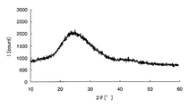
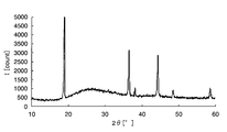
- FIG. 1 is a chart showing X-ray diffraction results of amorphous iron oxide.
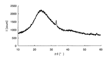
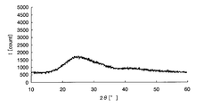
- FIG. 2 is a chart showing X-ray diffraction results of crystalline iron oxide.
- FIG. 3 is a cyclic voltammogram showing the results of a cyclic voltammetry test using a metal oxide exhibiting a lithium insertion / elimination reaction.
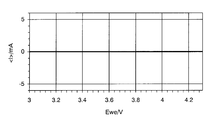
- FIG. 4 is a cyclic voltammogram showing the results of a cyclic voltammetry test using a metal oxide that does not exhibit a lithium insertion / elimination reaction.
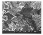
- FIG. 5 is an electron micrograph obtained by observing the cross section of Example 1 perpendicular to the current collector surface at a magnification of 10,000 using a scanning electron microscope (SEM).
- SEM scanning electron microscope
- FIG. 6 is a graph showing the X-ray diffraction results of the electrode active material layer of Example 1.
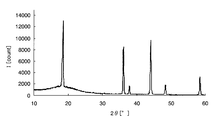
- FIG. 7 is a graph showing the X-ray diffraction results of iron oxide obtained by heating under the same conditions as in Example 1.
- FIG. 8 is a graph showing an X-ray diffraction result of lithium manganate as the positive electrode active material particles.
- FIG. 9A is a diagram showing a non-aqueous electrolyte secondary battery.
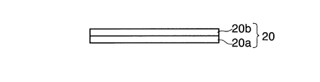
- FIG. 9B is a diagram showing an electrode plate for a non-aqueous electrolyte secondary battery.
- the electrode plate for nonaqueous electrolyte secondary batteries of the present invention the method for producing the electrode plate for nonaqueous electrolyte secondary batteries, and the mode for carrying out the nonaqueous electrolyte secondary battery will be described in order.
- a lithium ion secondary battery will be described as an example of the nonaqueous electrolyte secondary battery of the present invention unless otherwise specified.
- the characteristic of the metal oxide in the present invention “does not show alkali metal ion insertion / release reaction”, unless otherwise specified, lithium ions are used as examples of alkali metal ions, Insertion / desorption will be described.
- the electrode plate of this invention contains both the positive electrode plate and negative electrode plate which are used for a nonaqueous electrolyte secondary battery. Therefore, in the following description, unless otherwise specified, the positive electrode plate and the negative electrode plate will be collectively described as electrode plates, and the positive electrode plate and the negative electrode plate will be described as necessary.
- the electrode plate 20 for a nonaqueous electrolyte secondary battery of the present embodiment includes a current collector 20a and an electrode active material layer 20b formed on at least a part of the surface of the current collector 20a. And.
- the electrode active material layer 20 includes electrode active material particles, a binder, and a carbon component that is distinguished from a conductive material.
- the binder is an amorphous metal oxide that does not show alkali metal ion insertion / extraction reaction.
- the electrode active material layer is a current collector made of a metal oxide in which the electrode active material particles are not a resin binder as in the prior art but are amorphous and do not show an alkali metal ion insertion / release reaction such as lithium ions. It is fixed on top and contains a carbon component that is distinguished from a conductive material.
- the thickness of the electrode active material layer can be appropriately designed in consideration of electric capacity and input / output characteristics required for the electrode plate. Generally, the thickness is designed to be 200 ⁇ m or less, more generally 100 ⁇ m or more and 150 ⁇ m or less. However, particularly in this embodiment, since the electrode active material layer can be formed very thin, an electrode active material having a film thickness of 300 nm or more and 200 ⁇ m or less depends on the particle diameter of the electrode active material particles used. A material layer can be formed. From the viewpoint that a high capacity can be obtained while improving the input / output characteristics, the thickness of the electrode active material layer is particularly preferably 300 nm to 30 ⁇ m, and more preferably 500 nm to 11 ⁇ m.
- the electrode active material particles used have a small particle diameter, and are at least a particle diameter equal to or smaller than the film thickness of the electrode active material layer. This means that this greatly contributes to the improvement of the input / output characteristics.
- the electrode active material layer is thin as described above, the moving distance of the electrons moving between the electrode active material particles and the current collector in the electrode active material layer is shortened. The resistance can be lowered, and as a result, it can contribute to the improvement of the input / output characteristics, which is desirable.
- the lower limit of the thickness of the electrode active material layer mainly depends on the particle diameter of the electrode active material particles used, and as the particle diameter of usable electrode active material particles is reduced, It is possible to make the film thickness thinner than the above range.
- the electrode active material layer preferably has voids to the extent that the electrolytic solution can permeate, and the porosity in the electrode active material layer is generally 15 to 40%, more preferably 20 to 40%. It is. Below, the substance contained in an electrode active material layer is demonstrated concretely.
- Electrode active material particles As the electrode active material particles contained in the electrode active material layer, positive electrode active material particles or negative electrode active materials that can be charged / discharged and exhibit lithium ion insertion / release reactions generally used in electrode plates for non-aqueous electrolyte secondary batteries are used. If it is a substance particle, it will not specifically limit. That is, in this embodiment, the electrode active material layer is bonded to each other by interposing a metal oxide between the particles such as the electrode active material particles or between the electrode active material particles and the current collector on the current collector. The metal oxide acts as a binder regardless of the type and shape of the electrode active material particles.
- the metal oxide contained in the electrode active material layer of the present embodiment does not show an alkali metal ion insertion / release reaction, it affects the reaction of any electrode active material particles.
- the electrode active material particles can be used without any particular limitation.
- specific examples of the positive electrode active material particles include, for example, LiCoO 2 , LiMn 2 O 4 , LiNiO 2 , LiFeO 2 , Li 4 Ti 5 O 12.
- active material particles such as lithium transition metal composite oxides such as LiFePO 4 .
- the negative electrode active material particles include active material particles made of carbonaceous material such as natural graphite, artificial graphite, amorphous carbon, carbon black, or those obtained by adding different elements to these components, Alternatively, a material that exhibits an insertion / extraction reaction of lithium ions, such as a metal oxide such as Li 4 Ti 5 O 12 , metal lithium and an alloy thereof, tin, silicon, and an alloy thereof can be given.
- the particle diameter of the electrode active material particles used in the present embodiment is not particularly limited, and those having an arbitrary size can be appropriately selected and used. However, the smaller the particle diameter, the larger the total surface area of the electrode active material particles in the electrode active material layer can be increased. It is desirable to do. Thus, the fact that the size of the particle diameter can be selected without any particular limitation is noted as an advantageous effect of the present embodiment. That is, in the production of a conventional electrode plate, it is difficult to use electrode active material particles having a small particle diameter because of a significant increase in the viscosity of the electrode active material layer forming composition.
- the electrode active material particles having an arbitrary particle size can be contained in the electrode active material layer, the surface area of the electrode active material particles in the electrode active material layer is increased.
- the reason why it is possible to use electrode active material particles having a smaller particle diameter is not clear, but a metal oxide is generated instead of the conventional resin binder. This is considered to be due to the addition of a metal element-containing compound or an organometallic compound to the electrode active material layer forming composition.
- the viscosity of the composition becomes high and adjustment thereof is difficult. Yes, the handleability was poor.
- the particle diameter of 11 ⁇ m or less can be easily obtained.
- An electrode plate provided with an electrode active material layer containing electrode active material particles can be obtained. As described above, it is desirable that the particle diameter of the electrode active material particles be 11 ⁇ m or less from the viewpoint of obtaining high input / output characteristics after sufficiently ensuring the handleability of the electrode active material layer forming composition.
- the viscosity of the electrode active material layer forming composition can be obtained even if an electrode plate having a conventional electrode active material layer using a resin binder is used. Became too high to lose fluidity and could not be applied to mass production equipment such as a printing press. Although it is possible to increase the fluidity of the electrode active material layer forming composition by adding a large amount of solvent, it takes a long time to dry and is not substantial, and in particular, production by a winding device is impossible. there were.
- the viscosity of the electrode active material layer forming composition is maintained moderately and the fluidity is good, so that mass production is possible. It can be applied to equipment. Therefore, it is desirable that the particle diameter of the electrode active material particles be 5 ⁇ m or less from the viewpoint of producing an electrode plate exhibiting high input / output characteristics by mass production equipment.
- an electrode active material layer forming composition is used. It was difficult to disperse the electrode active material particles in the material, and this was not feasible.
- the present embodiment even if electrode active material particles having a particle size of 1 ⁇ m or less are used, the dispersibility in the electrode active material layer forming composition is good, and the electrode active material particles of the size are excellent.
- the contained electrode active material layer can be formed on the current collector. Therefore, it is very advantageous and desirable to use electrode active material particles having a particle diameter of 1 ⁇ m or less in the present embodiment. From the above viewpoint, in the present embodiment, the particle diameter of the electrode active material particles is further selected to be 500 nm or less, more preferably 100 nm or less.
- the particle diameter of the electrode active material particles shown in the present invention and the present specification is an average particle diameter (volume median particle diameter: D50) measured by laser diffraction / scattering particle size distribution measurement.
- the particle diameter of the electrode active material contained in the electrode active material layer can be measured by using an image analysis type particle size distribution measurement software (manufactured by Mountec Co., Ltd., MAC VIEW).
- Binder metal oxide The metal oxide contained as a binder in the electrode active material layer is an oxide of a metal element that is generally understood to be a metal, and is an amorphous metal that does not exhibit a lithium ion insertion / release reaction If it is an oxide, it will not specifically limit.
- metal elements examples include Li, Be, Na, Mg, Al, Si, K, Ca, Sc, Ti, V, Cr, Mn, Fe, Co, Ni, Cu, Zn, Ga, Rb, Sr, Y, Zr, Nb, Mo, Tc, Ru, Rh, Pd, Ag, Cd, In, Sn, Cs, Ba, Hf, Ta, W, Re, Os, Ir, Pt, Au, Hg, Tl, Pb, Bi, Fr, Ra, Ce, etc. can be mentioned.
- oxides of metal elements belonging to the third to fifth periods are present as binders in the electrode active material layer.
- the input / output characteristics are improved more favorably, which is preferable. That is, Na, Mg, Al, Si, K, Ca, Sc, Ti, V, Cr, Mn, Fe, Co, Ni, Cu, Zn, Ga, Rb, Sr, Y, Zr, Nb, Mo, Tc, More preferably, a metal oxide containing a metal element selected from the group consisting of Ru, Rh, Pd, Ag, Cd, In, and Sn is present as a binder in the electrode active material layer.
- titanium oxide is inexpensive and easy to handle, and is contained as a binder in the electrode active material layer. In this case, it is possible to show a very excellent effect of improving the input / output characteristics. That is, in the electrode plate for a non-aqueous electrolyte secondary battery according to the present embodiment including an electrode active material layer containing titanium oxide as a binder, a high charge / discharge rate (discharge capacity maintenance) of 80% or more at a discharge rate of 50C. Rate), and can sufficiently cope with a large apparatus such as an automobile.
- the metal oxide in this embodiment is a metal oxide in which oxygen is bonded to any one of the above metal elements, or two or more metal elements selected from the above metal elements. Any of the mixed metal oxides may be included.
- examples of metal oxides in which oxygen is bonded to one metal element include sodium oxide, magnesium oxide, aluminum oxide, silicon oxide, potassium oxide, calcium oxide, scandium oxide, titanium oxide, vanadium oxide, chromium oxide, and oxide. Examples thereof include manganese, iron oxide, cobalt oxide, nickel oxide, zinc oxide, gallium oxide, strontium oxide, yttrium oxide, zirconium oxide, molybdenum oxide, ruthenium oxide, tantalum oxide, tungsten oxide, and cerium oxide.
- Examples of composite metal oxides containing two or more metal elements that can be used as the metal oxide in this embodiment include, for example, cerium oxide doped with gadolinium and yttrium. Examples thereof include zirconium oxide, mixed oxide of iron and titanium, oxide mixed with indium and tin, nickel oxide doped with lithium, and the like. The examples of the metal oxide described in this paragraph do not limit the metal oxide in the present invention.
- An object is an amorphous metal oxide that does not exhibit lithium ion insertion / release reaction, and can fix electrode active material particles on a current collector without using a resin binder. Any of them may be used.
- the metal oxide mentioned above can be contained in an electrode active material layer by 1 type, or 2 or more types of combination.
- Binder compounding ratio In the present embodiment, the mixing ratio of the metal oxide and electrode active material particles in the electrode active material layer is not particularly specified, and the type and size of the electrode active material particles used, the type of metal oxide, the electrode It can be determined as appropriate in consideration of the functions required for. However, in general, the larger the amount of electrode active material particles in the electrode active material layer, the higher the electric capacity of the electrode. From this viewpoint, the electrode active material particles present in the electrode active material layer It can be said that a smaller amount of the metal oxide is more preferable. More specifically, in the electrode active material layer, when the weight ratio of the electrode active material particles is 100 parts by weight, the weight ratio of the metal oxide is 1 part by weight or more and 50 parts by weight or less. be able to.
- the electrode active material particles may not be satisfactorily fixed on the current collector.
- the description of the upper limit of the weight ratio of the metal oxide is not intended to exclude the presence of the metal oxide exceeding the upper limit in the present invention. This shows that the active material particles can be fixed on the current collector with a smaller amount of metal oxide in order to increase the electric capacity of the electrode.
- the metal oxide is specified to be amorphous.
- the amorphous metal oxide means that the metal oxide or a sample containing the metal oxide is analyzed by an X-ray diffractometer and the peak of the metal oxide is not detected. To do. For example, taking iron as an example of the metal element, crystalline iron oxide and amorphous iron oxide will be described using specific analysis results in the respective X-ray diffractometers.
- Samples 1 and 2 were then prepared by applying the above sample solution on a glass substrate. Sample 1 was heated at 300 ° C. for 1 hour, while sample 2 was heated at 500 ° C. for 1 hour. Subsequently, the film-forming surfaces of samples 1 and 2 after heating were scraped to obtain analytical samples 1 and 2, respectively, and composition analysis was performed on these samples.
- peaks can be confirmed around 32 ° and 58 ° on the horizontal axis, and it is understood that crystalline iron oxide is generated on the glass substrate.
- the metal element is an oxide is confirmed by composition analysis, and whether the metal oxide is amorphous from the chart obtained by the X-ray diffractometer, It can be confirmed whether it is crystalline.
- a metal oxide is specified to the thing which does not show alkali metal ion insertion elimination reaction. The reason is that the metal oxide does not electrochemically react with alkali metal ions such as lithium ions. As a result, no expansion or reactant is generated due to the electrochemical reaction of the metal oxide, and as a result, deterioration due to expansion or deficiency of the metal oxide in the electrode active material layer is suppressed.
- the presence or absence of a lithium ion insertion / elimination reaction of the metal oxide can be confirmed by an electrochemical measurement (cyclic voltammetry: CV) method.
- CV test will be described below.
- the electrode potential is swept from 3.0 V to 4.3 V in the appropriate voltage range of the active material, for example, assuming lithium ions as alkali metal ions and LiMn 2 O 4 as the metal oxide. After that, the work of returning to 3.0 V is repeated about three times.
- the scanning speed is preferably 1 mV / sec. For example, in the case of LiMn 2 O 4 , as shown in FIG.
- an oxidation peak corresponding to the Li elimination reaction of LiMn 2 O 4 appears in the vicinity of about 3.9 V, and the Li insertion reaction occurs in the vicinity of about 4.1 V.
- a corresponding reduction peak appears, whereby the presence or absence of lithium ion insertion / extraction reaction can be confirmed.
- FIG. 4 when no peak appears, it can be determined that there is no lithium ion insertion / release reaction.
- the fact that the metal oxide does not exhibit a lithium ion insertion / release reaction does not mean the electrical property inherent to the metal oxide, but is contained as a binder in the electrode active material layer.
- the metal oxide does not exhibit a lithium ion insertion / release reaction in a voltage range suitable for the electrode active material particles contained in the electrode active material. That is, in the electrode plate, it is important that the metal oxide does not substantially insert and desorb lithium ions.
- the presence or absence of lithium ion insertion / desorption reaction of the metal oxide that is expected to be contained in the electrode active material layer can be confirmed as described above. . Therefore, after confirmation in advance, a metal oxide that does not exhibit a lithium ion insertion / release reaction can be present as a binder in the electrode active material layer. On the other hand, whether or not a metal oxide that does not exhibit lithium ion insertion / release reaction is contained in the electrode active material layer in the electrode plate that has already been completed can be confirmed as follows, for example.
- the electrode plate can optionally further contain a conductive material in the electrode active material layer.
- a conductive material in the electrode active material layer, it is possible to ensure better electronic conductivity between each electrode active material and the current collector in the electrode active material layer, and to reduce the volume of the electrode active material layer itself. It is desirable because the resistivity can be lowered efficiently.
- the conductive material those usually used for electrode plates for non-aqueous electrolyte secondary batteries can be used, and conductive carbon materials such as particulate carbon black such as acetylene black and ketjen black are used. Illustrated.
- the average primary particle size of the conductive material is preferably about 20 nm to 50 nm.
- Carbon fiber is known as a different conductive material.
- the carbon fiber can conduct electricity very well in the length direction and can improve the fluidity of electricity.
- the fiber length is about 1 ⁇ m to 20 ⁇ m. Therefore, in addition to the particulate conductive material such as acetylene black described above, the effect of adding the conductive material can be improved by using carbon fiber together.
- the conductivity of the conductive material is generally expressed as an electrical resistivity, and an electrical resistance of about 0.14 to 0.25 ⁇ cm is shown.
- the said average primary particle size is calculated
- the content is not particularly limited, but generally, the proportion of the conductive material is 5 parts by weight or more and 20 parts by weight with respect to 100 parts by weight of the electrode active material particles. It is desirable that the amount is not more than parts by weight.
- the electrode active material layer contains a carbon component (hereinafter also simply referred to as “carbon component”) that is distinguished from the conductive material.
- the carbon component is also distinguished from a conductive material that is optionally added, and particularly in the negative electrode plate, it is present in the electrode active material layer separately from the negative electrode active material particles.
- the presence of the carbon component in the electrode active material layer is generally greater than the amount of carbon derived from the electrode active material or conductive material than the carbon source detected by the composition analysis of the electrode active material layer in the obtained electrode plate. Whether it can be confirmed. However, when the amount of the carbon component is very small, the remaining amount may not be reflected in the composition analysis. The present inventors have confirmed that even such a small amount of carbon component actually contributes to the improvement of the input / output characteristics of the electrode plate by being present in the electrode active material layer. For example, the electrode active material layer forming composition before the addition of the conductive material is applied on the substrate to form a coating film and heated at an appropriate heating temperature, so that a carbon component is present in the formed film. Preliminary experiments will be conducted to confirm this fact.
- the electrode active material layer forming composition to which a conductive material or the like is added is actually applied onto the current collector and heated under the same heating conditions as in the preliminary experiment.
- the electrode plate obtained as described above it is understood that carbon components other than carbon constituting the conductive material remain in the electrode active material layer regardless of the result of the composition analysis of the electrode active material layer.
- TEM transmission electron microscope
- STEM method scanning transmission electron microscope
- Carbon element can be confirmed by element mapping shown by nano-order elemental analysis with a detector.
- the carbon component contained in the electrode active material layer can also be confirmed by evaluating the nano-order state with an EELS spectrometer and obtaining a composition contrast image with a HAADF detector.
- the element mapping and the method using the composition contrast image are particularly useful for the negative electrode plate among the electrode plates. That is, negative electrode active material particles such as graphite or conductive material particles exist in the electrode active material layer as an aggregate of substantially pure carbon atoms.
- the carbon component is not an aggregate of carbon atoms such as a scale of a conductive material, but the carbon component can be confirmed by the presence of carbon elements dispersed in other components. Therefore, in the carbon element mapping, the carbon component can be confirmed by the presence of carbon elements scattered in the electrode active material.
- the carbon component may be contained in the metal oxide in the electrode active material layer. That is, when the metal oxide is generated in the electrode active material layer, a carbon component may be contained to generate these binder materials. Even in such a case, high input / output characteristics and good performance are obtained. Excellent effects such as maintaining proper processing characteristics are exhibited.
- the carbon component is derived from carbon in a substance added to the electrode active material layer forming composition, such as an organic substance or an organometallic compound described later, and formed by adjusting the heating temperature during the manufacturing process. Although it can obtain by making the said carbon remain in the electrode active material layer made, it is not limited to this. More specifically, an electrode active material layer forming composition before adding a carbon material such as a conductive material or negative electrode active material particles composed of graphite is applied onto a substrate to form a coating film, Preliminary experiments are performed to preliminarily confirm that carbon components are present in the formed film by heating at a heating temperature or an appropriate heating atmosphere.
- an electrode active material layer forming composition containing a necessary material is applied onto a current collector, and a heating step is performed under the same conditions as in the preliminary experiment, whereby a negative electrode composed of a conductive material or graphite.
- An electrode plate including an electrode active material layer containing a carbon component other than a carbon material such as active material particles can be produced.
- the input / output characteristics can be further improved by including a carbon component that is distinguished from the conductive material in the electrode active material layer.
- the carbon component by including the carbon component, the flexibility of the electrode active material layer is improved, and the present inventors have shown that excellent processing characteristics can be obtained without using a resin binder. Found by research. Therefore, when processing the electrode plate of the present embodiment, or when manufacturing a non-aqueous electrolyte secondary battery using the manufactured electrode plate of the present embodiment, the electrode plate is curved Even so, peeling of the electrode active material layer from the current collector and dropping of the active material particles do not occur, and a very excellent electrode plate can be provided.
- the amount of the carbon component distinguished from the conductive material in the electrode active material layer is not particularly limited, and even if it is a minute content that is not reflected in a general composition analysis, This can contribute to the improvement of input / output characteristics.
- the carbon component may be contained in a metal oxide as a binding material. In such a case, the carbon component is contained with respect to 100 mol% of the metal element contained in the metal oxide.
- the content is preferably 10 mol% or more, and the upper limit thereof is not particularly limited, but a content of 50 mol% or less can sufficiently contribute to the improvement of the input / output characteristics and the improvement of the processing characteristics.
- the electrode active material layer contains at least a carbon component that is distinguished from the electrode active material particles, the metal oxide that is the binder, and the conductive material, and the conductive material can be further added. Further optional additives may be contained within the scope not departing from the gist of the invention.
- the current collector is not particularly limited as long as it is generally used as an electrode current collector of an electrode plate for a non-aqueous electrolyte secondary battery.
- aluminum foil or nickel foil can be preferably used as the positive electrode current collector, and copper foil, aluminum foil, nickel foil or the like can be preferably used as the negative electrode current collector.
- the thickness of the current collector is not particularly limited as long as it is a thickness that can generally be used as a current collector for a nonaqueous electrolyte secondary battery electrode plate, but is preferably 10 to 100 ⁇ m, and preferably 15 to 50 ⁇ m. It is more preferable.
- the input / output characteristics of the electrode plate can be evaluated by determining the discharge capacity maintenance rate (%). That is, the discharge capacity retention rate is an evaluation of the discharge rate characteristics, and it is generally understood that the charge rate characteristics are similarly improved in an electrode plate with improved discharge rate characteristics. Therefore, when a desirable discharge capacity maintenance ratio is indicated, it is evaluated that the charge / discharge rate characteristics are improved, and as a result, the input / output characteristics are evaluated as improved. More specifically, the discharge rate 1C is set such that the theoretical value of the discharge capacity (mAh / g) of the active material is completed in 1 hour, and the discharge actually measured at the set discharge rate of 1C.
- the capacity (mAh / g) is set to a discharge capacity maintenance rate of 100%.
- the discharge capacity (mAh / g) when the discharge rate is further increased is measured, and the discharge capacity retention ratio (%) can be obtained from the following equation 1.
- the said discharge capacity is calculated
- the charge / discharge rate characteristics of the electrode plate vary depending on the type and particle diameter of the electrode active material particles used, the amount of the metal oxide that is the binder contained, the thickness of the electrode active material layer, and the like. In general, regarding the charge / discharge rate characteristics of the electrode plate for a non-aqueous electrolyte secondary battery, it is desirable that a discharge capacity maintenance rate of 50% or more is shown at a discharge rate of 50C or more, and more desirably 50% or more. It is desirable that the discharge capacity retention rate be shown at a discharge rate of 100 C or higher, and it can be evaluated that the charge / discharge rate characteristics are high.
- the electrode plate of the present embodiment can exhibit the high charge / discharge rate characteristics described above. However, it is desirable to pay attention to this point because a system capable of withstanding a large current is required when the discharge rate is 2000 C or higher.
- the discharge capacity retention rate is high, and the discharge capacity is 50 C when the discharge rate is 50 C. It is desirable that the maintenance rate be 50% or more, or 80% or more, and even 100%. If it is the electrode plate for nonaqueous electrolyte secondary batteries of this Embodiment, it is possible to show the high discharge maintenance factor shown above.
- the electrode plate for a non-aqueous electrolyte secondary battery according to the present embodiment as described above is amorphous without using a resin binder as in the prior art, and has an alkali ion insertion / desorption reaction.
- the electrode active material layer is formed by adhering the electrode active material particles on the current collector due to the presence of the metal oxide that does not show the above.
- the output is very high. It becomes possible to exhibit input characteristics.
- the inclusion of a carbon component that is distinct from the conductive material exhibits very desirable input / output characteristics.
- this electrode plate has good film adhesion of the electrode active material layer to the current collector as in the case of a conventional electrode plate using a resin binder, and thus the film forming property of the electrode active material layer is good. It is.
- 1st aspect of the manufacturing method of this invention is 1 type, or 2 or more types of metal element content for producing
- An electrode active material layer forming composition containing at least a compound and an organic substance that is a material capable of imparting a carbon component that is distinguished from a conductive material is prepared, and using this, a coating process described later and heating The steps are performed in order.
- the metal element-containing compound is selected in advance so that the metal oxide generated in the heating step is a metal oxide that does not exhibit an alkali metal ion insertion / release reaction.
- the heating temperature in the heating step is equal to or higher than the thermal decomposition start temperature of the metal element-containing compound and is lower than the crystallization temperature of the metal oxide generated in the heating step, and the carbon derived from the organic matter Is set to a temperature at which it can remain in the electrode active material layer as a carbon component distinguished from the conductive material.
- the electrode active material particles and one or more organic metal compounds selected as a material for generating a metal oxide as a binding material are at least
- the electrode active material layer forming composition to be contained is prepared, and the coating step and the heating step described later are sequentially performed using the composition.
- the organometallic compound is selected in advance so that the metal oxide generated in the heating step is a metal oxide that does not exhibit an alkali metal ion insertion / release reaction.
- the heating temperature in the heating step is equal to or higher than the thermal decomposition start temperature of the organometallic compound, which is lower than the crystallization temperature of the metal oxide generated in the heating step, and carbon derived from the organometallic compound. Is set to a temperature at which it can remain in the electrode active material layer as a carbon component distinguished from the conductive material.
- a third aspect of the production method of the present invention is a method in which electrode active material particles, one or more organometallic compounds selected as a material for generating a metal oxide as a binder, and a conductive material are used.
- An electrode active material layer-forming composition containing at least an organic substance that is capable of imparting a carbon component that is distinct from the material is prepared, and using this, an application step and a heating step described later are sequentially performed. To do.
- the organometallic compound is selected in advance so that the metal oxide generated in the heating step is a metal oxide that does not exhibit an alkali metal ion insertion / release reaction.
- the heating temperature in the heating step is equal to or higher than the thermal decomposition start temperature of the organometallic compound and is lower than the crystallization temperature of the metal oxide produced in the heating step, and at least the organometallic compound or the organic matter
- the temperature is such that the derived carbon can remain in the electrode active material layer as a carbon component distinguished from the conductive material.
- one important point in the preparation of the electrode active material layer forming composition is that a material containing carbon is blended in a material other than a conductive material that is optionally added.
- the carbon component that is distinguished from the conductive material can remain in the produced electrode active material layer. That is, as described above, the electrode active material layer forming composition is blended with at least an organic substance that can impart a carbon component that is different from a conductive material, or an organic metal that is a metal oxide generation material. It is necessary to add the compound. Below, it demonstrates in detail regarding a manufacturing method.
- Electrode active material particles Since the electrode active material particles contained in the electrode active material layer forming composition are the same as the electrode active material particles already described above, the description thereof is omitted here. In addition, in the manufacturing method of an electrode plate, the particle diameter of the electrode active material particle used can select a desired magnitude
- the electrode active material layer forming composition may contain a metal element-containing compound or an organometallic compound as a metal oxide production material to be produced.
- the metal element-containing compound and the organometallic compound may be collectively referred to as a binder generation material.
- the binder material generating material is a metal oxide generating material for fixing the electrode active material particles on the current collector as the binder material.
- the binder generation material When the binder generation material is heated on the substrate at a temperature equal to or higher than the thermal decomposition start temperature, it can be thermally decomposed and oxidized to form a film.
- the present inventors In studying the problems of the present invention, the present inventors have studied the inclusion of electrode active material particles in the metal oxide film when forming the metal oxide film on the substrate, and have earnestly studied. As a result, it has been found that the electrode active material particles can be fixed on the substrate due to the presence of the metal oxide even if the amount of the metal oxide is reduced.
- the present inventors without using a resin binder, under the idea of including electrode active material particles in the binder material to be formed into a film, the binder material generating material, the electrode active material particles, Was prepared, applied on the current collector, and tried to heat.
- the electrode active material particles are collected even if the amount of the binder material generated on the current collector is significantly reduced to the extent that the binder material exists in the electrode active material layer mainly composed of the electrode active material particles. It has been found that it is fixed on the electric body.
- the binder-generating material used in the production method of the present invention contains a metal element that can be thermally decomposed and oxidized to form a film within the scope of the present invention, and Any binder may be selected as long as the binder produced on the current collector does not show an insertion / release reaction of alkali metal ions such as lithium ions.
- the organometallic compound is a binding material generating material, and the carbon atoms contained in the organometallic compound are contained in the electrode active material layer. It is a compound that can be imparted as a carbon component that is distinguished from the material.
- the binder produced from the binder substance-generating material used does not show alkali metal ion insertion / release reaction.
- the binder material is formed by applying to and heated, and can be confirmed by the cyclic voltammetry method described above.
- the metal element-containing compound includes Li, Be, Na, Mg, Al, Si, K, Ca, Sc, Ti, V, Cr, Mn, Fe, Co, Ni, Cu, Zn, Ga, Rb, Sr, Y, Zr, Nb, Mo, Tc, Ru, Rh, Pd, Ag, Cd, In, Sn, Cs, Ba, Hf, Ta, W, Re, Os, Ir, Pt, Au, Hg, Any compound selected from a general metal element group such as Tl, Pb, Bi, Fr, Ra, and Ce may be used as long as it is a compound containing two or more metal elements.
- the input / output characteristics of the generated electrode plate become higher. It is preferable because of its tendency. That is, Na, Mg, Al, Si, K, Ca, Sc, Ti, V, Cr, Mn, Fe, Co, Ni, Cu, Zn, Ga, Rb, Sr, Y, Zr, Nb, Mo, Tc, A compound containing one or more metal elements selected from Ru, Rh, Pd, Ag, Cd, In, and Sn is preferable as the metal element-containing compound.
- the metal element-containing compound containing the metal element for example, a metal salt is preferably used.
- the metal salt include chloride, nitrate, sulfate, perchlorate, phosphate, bromate and the like.
- chlorides and nitrates are preferable because they are easily available as general-purpose products.
- nitrate is preferably used because it is inexpensive.
- metal salts include magnesium chloride, aluminum nitrate, aluminum chloride, calcium chloride, titanium tetrachloride, vanadium oxosulfate, ammonium chromate, chromium chloride, ammonium dichromate, chromium nitrate, chromium sulfate, manganese nitrate , Manganese sulfate, iron (I) chloride, iron (III) chloride, iron (III) nitrate, iron (II) sulfate, iron (III) sulfate, cobalt chloride, cobalt nitrate, nickel chloride, nickel nitrate, copper chloride, nitric acid Copper, zinc chloride, yttrium nitrate, yttrium chloride, zirconium chloride oxide, zirconium nitrate oxide, zirconium tetrachloride, silver chloride, indium nitrate, tin sulfate,
- the organometallic compound means a compound containing a metal and carbon, and includes both a metal complex containing a carbon element and a metal salt containing a carbon element. More specifically, the organometallic compound may be any one selected from a general metal element group as listed in the above metal element-containing compound, or a compound containing two or more metal elements and carbon. That's fine. In addition, in the organometallic compound, it is preferable that a metal element belonging to 3 to 5 cycles among the metal element group is contained, similarly to the metal element-containing compound.
- the metal salt examples include acetate and oxalate. Among them, acetate is preferably used because it is easily available as a general-purpose product. Specific examples of the metal salt include scandium acetate, chromium acetate, iron (II) acetate, cobalt acetate, nickel acetate, zinc acetate, silver acetate, indium acetate, cerium acetate, Examples thereof include cerium oxalate, lead acetate, lanthanum acetate, strontium acetate, palladium acetate, and barium acetate.
- Metal complexes include magnesium diethoxide, aluminum acetylacetonate, calcium acetylacetonate dihydrate, calcium di (methoxyethoxide), calcium gluconate monohydrate, calcium citrate tetrahydrate, salicylic acid Calcium dihydrate, titanium lactate, titanium acetylacetonate, tetraisopropyl titanate, tetranormal butyl titanate, tetra (2-ethylhexyl) titanate, butyl titanate dimer, titanium bis (ethylhexoxy) bis (2-ethyl-3-hydroxyhexyl) Soxide), diisopropoxytitanium bis (triethanolamate), dihydroxybis (ammonium lactate) titanium, diisopropoxytitanium bis (ethylacetoacetate) Titanium peroxo ammonium citrate tetrahydrate, dicyclopentadienyl iron (II), iron (II) lactate trihydrate, iron (III)
- the organometallic compound described above is distinguished from the metal element-containing compound described above depending on whether or not it contains carbon. Both the metal element-containing compound and the organometallic compound are binding material-generating materials. However, the difference in their use is that in the organometallic compound, the carbon element contained therein is electrically conductive in the electrode active material layer.
- the carbon component can be left as a distinctive carbon material, and the heating temperature in the heating step needs to be adjusted appropriately in order to leave the carbon element in the electrode active material layer. The heating temperature will be described later.
- the electrode active material layer provided on the electrode plate for a non-aqueous electrolyte secondary battery manufactured by the manufacturing method of the present invention is a binding material capable of fixing the electrode active material particles on the current collector. Any material can be appropriately selected and used as long as it is a material capable of producing a metal oxide.
- an organic substance that is different from the organometallic compound can be used as another compound for providing the carbon component remaining in the electrode active material layer.
- the organic substance include urethane resin, epoxy resin, ethyl cellulose, starch, polyethylene oxide, polyvinyl alcohol, and polyethylene glycol. These organic substances exhibit the effect of adjusting the viscosity when the electrode active material layer forming composition is prepared.
- An organic material that can also act as a viscosity modifier is blended in the electrode active material layer forming composition, and the composition is applied onto a current collector, and then heated at an appropriate temperature to form an electrode active material to be formed. The carbon component can remain in the material layer.
- the electrode active material layer forming composition may be mixed with a conductive material and other additives without departing from the spirit of the present invention.
- the solvent used in the electrode active material layer forming composition can be prepared as an electrode active material layer forming composition to which additives such as electrode active material particles, a binding material generating material, and an organic substance are added, and If it can remove in a heating process after apply
- lower alcohols having a total carbon number of 5 or less such as methanol, ethanol, isopropyl alcohol, propanol, butanol, diketones such as acetylacetone, diacetyl, benzoylacetone, ethyl acetoacetate, ethyl pyruvate, ethyl benzoylacetate, ethyl benzoylformate And ketoesters such as toluene, a single solvent such as toluene, or a mixed solvent composed of a combination of two or more thereof.
- diketones such as acetylacetone, diacetyl, benzoylacetone, ethyl acetoacetate, ethyl pyruvate, ethyl benzoylacetate, ethyl benzoylformate
- ketoesters such as toluene, a single solvent such as toluene, or a mixed solvent composed of
- the electrode active material layer forming composition comprises electrode active material particles, a binder forming material, an organic substance, and other additives added as necessary in an electrode active material layer scheduled to be formed on a current collector. These blending amounts are determined in consideration of the necessary amount.
- the solid content ratio is appropriately adjusted in consideration of the coating property on the current collector in the coating step and the removal of the solvent in the heating step. Generally, the solid content ratio in the electrode active material layer forming composition is adjusted to 30 to 70 wt%.
- any known coating method can be used as the coating method for the electrode active material layer forming composition.
- a coating film can be formed by applying to any region of the current collector surface by printing, spin coating, dip coating, bar coating, spray coating, or the like.
- the current collector surface is porous, has a large number of irregularities, or has a three-dimensional structure, it can be manually applied in addition to the above method.
- the current collector can further improve the film forming property of the electrode active material layer by performing corona treatment, oxygen plasma treatment, or the like in advance as necessary.
- the amount of the electrode active material layer forming composition applied to the current collector can be arbitrarily determined according to the application of the electrode plate to be produced, etc., but the electrode active material layer in the present embodiment is When it is desired to reduce the film thickness, the electrode active material layer formed by the heating process described later should be thinly applied so that the thickness is about 300 nm to 11 ⁇ m. Can do.
- the electrode active material layer forming composition to the current collector, the electrode active material particles and the binding material generating material (that is, the metal element-containing compound or the organometallic compound), or further A coating film for forming an electrode active material layer containing at least an organic substance (hereinafter sometimes simply referred to as “coating film”) is formed.
- Heating process Next, the heating process for heating the coating film formed in the coating process will be described.
- This heating step heats and thermally decomposes the binder-forming material present in the coating film to produce an amorphous metal oxide containing a metal element contained therein, and in the coating film It is performed for the purpose of removing the solvent contained in. Also, at this time, in order to leave carbon in at least one of the organometallic compound in the coating film or the organic substance further added in the electrode active material layer as a carbon component distinct from the conductive material, suitable heating is performed. It is necessary to adjust the temperature or heating atmosphere.
- the heating method is not particularly limited as long as it is a heating method or a heating apparatus that can heat the coating film at a desired heating temperature, and can be appropriately selected and carried out. Specific examples include a method of using a hot plate, an oven, a heating furnace, an infrared heater, a halogen heater, a hot air blower, or the like, or a combination of two or more.
- a hot plate When the current collector to be used is planar, it is preferable to use a hot plate or the like.
- the heating temperature in the heating step is equal to or higher than the thermal decomposition start temperature of the binder material generating material and lower than the crystallization temperature of the generated metal oxide, and at least of the organometallic compound and the organic substance to be added.
- the carbon contained in any one of the carbons is determined in a temperature range in which the carbon component that can be distinguished from the conductive material in the electrode active material layer can remain.
- the thermal decomposition starting temperature of the binding substance-generating material varies depending on the type of each compound.
- the metal element-containing compound or the organometallic compound contained in the coating film is heated and thermally decomposed, generally, it is rapidly oxidized to form a metal oxide. Therefore, as a preliminary test, a solution containing a metal element-containing compound or an organometallic compound is applied onto a substrate and heated, and the laminated film laminated on the substrate is scraped to make a sample.
- thermal decomposition start temperature of metal element-containing compound or “thermal decomposition start temperature of organometallic compound” means that the metal element-containing compound or organometallic compound is thermally decomposed by heating and contained in this It can be understood as the temperature at which element oxidation begins.
- the “crystallization temperature” means a temperature at which the metal oxide is crystallized after the metal atom contained in the electrode active material layer forming composition becomes a metal oxide.
- the metal oxide crystallizes at the crystallization temperature, and the crystallinity increases when the temperature is exceeded.
- the term “crystallization” refers to the crystal state in the X-ray diffractometer regardless of the crystallinity. This refers to the case where the peak shown is confirmed.
- the “crystallization temperature” in the present invention does not necessarily coincide with the intrinsic crystallization temperature of the metal oxide, and differs slightly from the intrinsic crystallization temperature depending on the state in the electrode active material layer forming composition. There is a case. Therefore, in consideration of this point, it is desirable to confirm in advance the crystallization temperature of the metal oxide in the electrode active material layer forming coating film.
- the above heating temperature is “below the crystallization temperature” of the metal oxide to be produced when the metal oxide contained in the electrode active material layer formed on the current collector is in an amorphous state. It is a temperature that allows it to exist at.
- the temperature is preliminarily applied by applying a solution containing the binding substance generating material on the substrate, heating at a temperature equal to or higher than the thermal decomposition start temperature of the binding substance generating material, and being made of a metal oxide on the substrate. Form a film, scrape the film into a sample, evaluate the crystallinity using an X-ray diffractometer, and understand that if the crystal peak is not confirmed, it was heated at a temperature below the crystallization temperature. can do.
- specific examples of the temperature at which carbon contained in the organic metal compound or the organic substance can remain in the electrode active material layer as a carbon component that can be distinguished from the conductive material are as follows, for example. That is, when an organometallic compound is used as the compound imparted to the carbon component that is distinguished from the conductive material remaining in the electrode active material layer, the organic group is separated from the organometallic compound, and at least the organic group It is sufficient that a part of the temperature is carbonized without being lost in the heating step and can remain in the electrode active material layer as a carbon component that is distinguished from the conductive material. Similarly, when an organic material is used, it is sufficient that at least a part of the organic group in the organic material is carbonized without disappearing in the heating step and can remain in the electrode active material layer.
- an electrode active material in the electrode plate of the present embodiment using an electrode active material layer-forming composition containing at least electrode active material particles, a metal element-containing compound, and an organic substance.
- the heating temperature in the heating step is equal to or higher than the thermal decomposition start temperature of the metal element-containing compound, and is lower than the crystallization temperature of the metal oxide generated in the heating step, and
- the organic material-derived carbon may be set to a temperature at which it can remain as a carbon component that is distinguished from the conductive material in the electrode active material layer.
- the heating step is equal to or higher than the thermal decomposition start temperature of the organometallic compound and is lower than the crystallization temperature of the metal oxide produced in the heating step, and the carbon derived from the organometallic compound is an electrode active material layer. What is necessary is just to set to the temperature which can remain
- the electrode active material layer in the electrode plate of the present embodiment is formed using an electrode active material layer forming composition containing at least electrode active material particles, an organometallic compound, and an organic substance.
- the heating temperature in the heating step is equal to or higher than the thermal decomposition start temperature of the organometallic compound and is lower than the crystallization temperature of the metal oxide produced in the heating step, and the organometallic compound and / or the organic substance. What is necessary is just to set to the temperature which the carbon contained in can remain
- the heating temperature at which a desired component can be present in the electrode active material layer is determined in advance in a preliminary experiment. It is desirable.
- the heating step when determining the heating temperature, it is desirable to sufficiently take into account the heat resistance of the current collector, electrode active material particles, conductive material, and the like used.
- the heat resistance temperature of a copper foil generally used as a current collector for a negative electrode plate is about 200 ° C. because it is oxidized in an air atmosphere, and about 1080 ° C. in an inert gas atmosphere.
- the heat resistance temperature of the aluminum foil is around 660 ° C. For this reason, when the said heating temperature exceeds the said heat-resistant temperature, there exists a possibility that a collector may be damaged.
- the heating atmosphere in the heating step is not particularly limited, and can be appropriately determined in consideration of the material used for manufacturing the electrode plate, the heating temperature, the oxygen potential of the metal element, and the like.
- the heating step can be preferably performed because there is no possibility that the aluminum foil is oxidized even if the heating step is performed in an air atmosphere.
- copper foil is used as the current collector, it is not desirable because it is oxidized when the heating step is performed in an air atmosphere.
- an inert gas atmosphere it is preferable to heat in an inert gas atmosphere, a reducing gas atmosphere, or a mixed gas atmosphere of an inert gas and a reducing gas.
- the heating step is performed in an atmosphere that does not contain sufficient oxygen gas
- the metal oxide is generated in the electrode active material layer
- the oxidation of the metal element in the metal element-containing compound or organometallic compound is performed. Needs to be realized by the combination of oxygen and metal element in the compound contained in the electrode active material layer forming composition, so it is necessary to use the compound containing oxygen element in the compound to be used There is.
- the atmosphere in which the manufacturing method is carried out is not particularly limited to a specific atmosphere, and is an inert gas atmosphere, a reducing gas atmosphere, or a gas atmosphere in which an inert gas and a reducing gas are mixed.
- the manufacturing method can be carried out as appropriate.
- an inert gas atmosphere a manufacturing method can be implemented in the atmosphere of argon gas and nitrogen gas.
- a reducing gas atmosphere a manufacturing method can be implemented in the atmosphere of hydrogen gas and carbon monoxide gas.
- the input / output characteristics are improved by a simple method and a general-purpose material as compared with a conventional electrode plate.
- An electrode plate for a non-aqueous electrolyte secondary battery can be manufactured.
- an electrode active material layer-forming composition prepared by containing at least a metal element-containing compound, electrode active material particles, and an organic substance, or an organic metal compound and electrode active material particles that are binding material generating materials.
- the electrode active material layer-forming composition prepared and contained exhibits a viscosity that allows good application to the current collector to be maintained regardless of the particle diameter of the contained electrode active material particles. Therefore, in a conventional electrode active material layer forming composition using a resin binder, it is possible to use electrode active material particles having a small particle diameter, which are difficult to use due to a significant increase in viscosity.
- paintability to the electrical power collector of the said electrode active material formation composition is favorable, it is also possible to apply
- the nonaqueous electrolyte secondary battery 10 is generally provided between the negative electrode 14 and the negative electrode plate 15, the positive electrode 16 and the positive electrode plate 17, and between the negative electrode plate 15 and the positive electrode plate 17.
- the separator 13 is provided.
- the negative electrode 14, the negative electrode plate 15, the positive electrode 16, the positive electrode plate 17, and the separator 13 are accommodated in the container 11.
- the separator 13 is made of a polyethylene porous film.
- the container 11 is hermetically sealed with the non-aqueous electrolyte 19 filled in the container 11.
- the electrode plate according to the present embodiment described above is used as the positive electrode plate and / or the negative electrode plate.
- the electrode plate of the present embodiment has very excellent input / output characteristics. Therefore, by using such an electrode plate, the performance of the electrode plate is exhibited also in the nonaqueous electrolyte secondary battery of the present embodiment, and the input / output characteristics of the battery itself are improved.
- the negative electrode plate is appropriately selected from conventionally known negative electrode plates for non-aqueous electrolyte secondary batteries.
- a copper foil such as an electrolytic copper foil or a rolled copper foil having a thickness of about 5 to 50 ⁇ m is used as a current collector, and an electrode in the negative electrode plate is formed on at least a part of the current collector surface.
- coating an active material layer forming composition, drying, and pressing as needed may be used.
- the electrode active material layer forming composition in the negative electrode plate generally includes an active material composed of a carbonaceous material such as natural graphite, artificial graphite, amorphous carbon, carbon black, or a material obtained by adding a different element to these components.
- an active material composed of a carbonaceous material such as natural graphite, artificial graphite, amorphous carbon, carbon black, or a material obtained by adding a different element to these components.
- negative electrode active material particles such as metal lithium and its alloys, tin, silicon, and alloys thereof, materials that can occlude and release lithium ions, and resinous binders, and other additions such as conductive materials as necessary
- the agent is dispersed and mixed, but is not limited thereto.
- the positive electrode plate is appropriately selected from conventionally known positive electrode plates for non-aqueous electrolyte secondary batteries. Can be used.
- a generally known positive electrode plate an aluminum foil having a thickness of about 5 to 50 ⁇ m is used as a current collector, and an electrode active material layer forming composition for forming a positive electrode plate is formed on at least a part of the surface of the current collector.
- a positive electrode plate formed by coating, drying, and pressing as necessary may be used.
- the electrode active material layer forming composition for forming the positive electrode plate generally includes lithium transition metal composite oxides such as LiCoO 2 , LiMn 2 O 4 , LiNiO 2 , LiFeO 2 , Li 4 Ti 5 O 12 , LiFePO 4.
- positive electrode active material particles such as a product, a resin binder, and other additives such as a conductive material as needed are dispersed and mixed, but the present invention is not limited thereto.
- Nonaqueous electrolyte is not particularly limited as long as it is generally used as a nonaqueous electrolyte for a nonaqueous electrolyte secondary battery, but a nonaqueous electrolyte in which a lithium salt is dissolved in an organic solvent is used. Preferably used.
- lithium salt examples include inorganic lithium salts such as LiClO 4 , LiBF 4 , LiPF 6 , LiAsF 6 , LiCl, and LiBr; LiB (C 6 H 5 ) 4 , LiN (SO 2 CF 3 ) 2 , LiC ( Organic compounds such as SO 2 CF 3 ) 3 , LiOSO 2 CF 3 , LiOSO 2 C 2 F 5 , LiOSO 2 C 4 F 9 , LiOSO 2 C 5 F 11 , LiOSO 2 C 6 F 13 , and LiOSO 2 C 7 F 15 Typical examples include lithium salts.
- inorganic lithium salts such as LiClO 4 , LiBF 4 , LiPF 6 , LiAsF 6 , LiCl, and LiBr
- LiB (C 6 H 5 ) 4 LiN (SO 2 CF 3 ) 2
- LiC Organic compounds such as SO 2 CF 3 ) 3 , LiOSO 2 CF 3 , LiOSO 2 C 2 F 5
- Examples of the organic solvent used for dissolving the lithium salt include cyclic esters, chain esters, cyclic ethers, and chain ethers.
- Examples of the cyclic esters include propylene carbonate, butylene carbonate, ⁇ -butyrolactone, vinylene carbonate, 2-methyl- ⁇ -butyrolactone, acetyl- ⁇ -butyrolactone, and ⁇ -valerolactone.
- chain esters examples include dimethyl carbonate, diethyl carbonate, dibutyl carbonate, dipropyl carbonate, methyl ethyl carbonate, methyl butyl carbonate, methyl propyl carbonate, ethyl butyl carbonate, ethyl propyl carbonate, butyl propyl carbonate, propionic acid alkyl ester, Examples include malonic acid dialkyl esters and acetic acid alkyl esters.
- Examples of the cyclic ethers include tetrahydrofuran, alkyltetrahydrofuran, dialkyltetrahydrofuran, alkoxytetrahydrofuran, dialkoxytetrahydrofuran, 1,3-dioxolane, alkyl-1,3-dioxolane, and 1,4-dioxolane.
- Examples of the chain ethers include 1,2-dimethoxyethane, 1,2-diethoxyethane, diethyl ether, ethylene glycol dialkyl ether, diethylene glycol dialkyl ether, triethylene glycol dialkyl ether, and tetraethylene glycol dialkyl ether. It is done.
- a conventionally known structure can be appropriately selected and used.
- the structure which winds a positive electrode plate and a negative electrode plate in the shape of a spiral via the separator like a polyethylene porous film, and accommodates in a battery container is mentioned.
- a structure in which a positive electrode plate and a negative electrode plate cut into a predetermined shape are stacked and fixed via a separator, and this is housed in a battery container may be employed.
- the lead wire attached to the positive electrode plate is connected to the positive electrode terminal provided in the outer container, while the lead wire attached to the negative electrode plate Is connected to a negative electrode terminal provided in the outer container, and the battery container is further filled with a nonaqueous electrification solution and then sealed to produce a nonaqueous electrolyte secondary battery.
- the electrode plate according to the present embodiment in which the input / output characteristics are improved as described above is used as the positive electrode plate and / or the negative electrode plate. Therefore, since the input / output characteristics of the electrode plate are improved as described above, the input / output characteristics of the non-aqueous electrolyte secondary battery are improved.
- Example 1 As the metal element-containing compound Fe (NO 3) 3 ⁇ 9H 2 O [ molecular weight: 404]
- further polyethylene glycol 200 manufactured by Kanto Chemical Co., Inc.
- was 10g mixed as organic lithium ion intercalation A raw material solution that produces a metal oxide that does not exhibit a desorption reaction was obtained.
- An aluminum plate having a thickness of 15 ⁇ m is prepared as a current collector, and an electrode prepared as described above is formed on one side of the current collector in such an amount that the weight of the electrode active material layer finally obtained is 15 g / m 2.
- the active material layer forming composition was applied with an applicator to form a coating film for forming an electrode active material layer.
- the current collector with the electrode active material layer-forming coating film formed on the surface was placed in a normal temperature electric furnace (muffle furnace, manufactured by Denken, P90) and heated to 260 ° C. over 1 hour. Thereafter, heating is performed for 5 hours while maintaining the temperature at 260 ° C., and the electrode active material layer suitable as the positive electrode active material layer is laminated on the current collector.
- a positive electrode plate was obtained. And after leaving the said positive electrode plate to room temperature, it cut
- Example 2 In the preparation of Example 1, the positive electrode plate for a non-aqueous electrolyte secondary battery obtained above was processed into a disk shape of a desired size. In this processing operation, an electrode active material was used. The working electrode could be formed without problems such as peeling of the layers. From this, it was confirmed that the film forming property of the electrode active material layer was good. Also in the examples and comparative examples shown below, good film formation means that, as described above, the positive electrode plate (or negative electrode plate) can be pulled out onto the disc without any problems. .
- the electrode active material layer is peeled off in the above-described punching process, or the electrode active material falls from the current collector to form a disc that can withstand use as a working electrode of a three-pole coin cell. If not, it is evaluated that the film forming property of the electrode active material layer is poor.
- composition analysis test Next, the electrode active material layer in Example 1 was shaved to obtain Sample 1. Then, composition analysis was performed by X-ray photoelectron spectroscopy (Electron Spectroscopy for Chemical Analysis) using Sample 1. As a result, Fe element was 9 atomic%, Mn element was 5 atomic%, O element was 53 atomic%, and C element was 33 atomic%. was detected. On the other hand, N element was not detected. As a result, it was confirmed that iron nitrate contained in the electrode active material layer forming coating film was thermally decomposed to produce iron oxide.
- Confirmation test 1 In addition, as a confirmation test 1, a positive electrode plate for a nonaqueous electrolyte secondary battery was prepared in the same manner as in Example 1 except that acetylene black and carbon fiber were not used, and a composition analysis test for the electrode active material layer was performed in the same manner as described above. As a result, the C element was 13 atomic%. Therefore, it was confirmed that the electrode active material layer in Example 1 contained carbon components derived from acetylene black and carbon fibers, and carbon components other than these conductive materials.
- Crystallinity evaluation Further, when the crystallinity of the sample 1 was evaluated with an X-ray diffractometer (XRD), the metal oxide contained in the electrode active material layer was amorphous as shown in FIG. all right.
- XRD X-ray diffractometer
- a raw material solution for forming the metal oxide (a solution before adding the positive electrode active material) was applied to a glass plate with a No. 4 bar and heated under the same heating conditions as those for electrode preparation.
- the result of evaluating the crystallinity using an X-ray diffractometer is shown in FIG.
- the crystallinity of M1090 which is a positive electrode active material particle, was evaluated using an X-ray diffractometer, and the results are shown in FIG. FIG.
- FIG. 7 is an X-ray diffraction result of iron oxide obtained by heating the raw material solution, and it was confirmed that the iron oxide was amorphous because no peak was confirmed.
- FIG. 8 is an X-ray diffraction result of lithium manganate as positive electrode active material particles, and a peak representing crystalline lithium manganate was confirmed. When analyzing FIG. 6 with reference to FIGS. 7 and 8, only the characteristic peak of crystalline lithium manganate is confirmed, and a broad pile of amorphous iron oxide appears again. confirmed.
- Cyclic voltammetry test (CV test): Further, a CV test was conducted using the positive electrode plate produced in Example 1. Specifically, the operation of first sweeping the electrode potential from 3.0 V to 4.3 V and then returning it to 3.0 V was repeated three times. The scanning speed was 1 mV / sec. The cyclic voltammogram showing the second cycle result corresponds to FIG. 3 described above. As is clear from FIG. 3, an oxidation peak corresponding to the Li elimination reaction of LiMn 2 O 4 was observed near 3.9 V, and a reduction peak corresponding to the Li insertion reaction was observed near 4.1 V. On the other hand, the raw material solution for forming the metal oxide (solution before adding the positive electrode active material) was applied to the aluminum substrate with a Miyabar No.
- LiPF 6 Lithium hexafluorophosphate
- EC ethylene carbonate
- DMC dimethyl carbonate
- concentration of LiPF 6 as the solute is 1 mol.
- the non-aqueous electrolyte was prepared by adjusting the concentration to be / L.
- Example 1 (15 mm diameter disc, weight of positive electrode active material contained: 2.72 mg / 1.77 cm 2 ) prepared as described above as a positive electrode plate was used as a working electrode, and a metal as a counter electrode and a reference electrode Using the non-aqueous electrolyte prepared above as the lithium plate and electrolyte, a tripolar coin cell was assembled, and this was designated as Example Test Cell 1.
- the example test cell 1 was subjected to the following charge / discharge test.
- Charge / discharge test In the example test cell 1, which is a tripolar coin cell manufactured as described above, first, the working electrode was subjected to a full charge as shown in the following charging test of the example test cell 1 in order to perform a discharge test of the working electrode.
- Example Test cell 1 was charged at a constant current (245 ⁇ A) under a 25 ° C. environment until the voltage reached 4.3 V. After the voltage reached 4.3 V, the voltage was 4.3 V. The current (discharge rate: 1C) was decreased until the current became 5% or less, and the battery was charged at a constant voltage, fully charged, and then suspended for 10 minutes.
- the “1C” means a current value (current value reaching the discharge end voltage) at which constant current discharge is performed using the tripolar coin cell and discharge is completed in one hour.
- the constant current was set such that a theoretical discharge amount of 90 mAh / g of lithium manganate as an active material was discharged in one hour at the working electrode in Example Test Cell 1.
- Example test cell 1 (Discharge test) Thereafter, the fully charged example test cell 1 was subjected to a constant current (245 ⁇ A) (discharged) in an environment of 25 ° C. until the voltage changed from 4.3 V (full charge voltage) to 3.0 V (discharge end voltage).
- a constant current discharge at a rate of 1 C) the cell voltage (V) on the vertical axis, the discharge time (h) on the horizontal axis, a discharge curve is created, and the working electrode (electrode plate for positive electrode of Example 1)
- the discharge capacity (mAh) was determined and converted to the discharge capacity (mAh / g) per unit weight of the working electrode.
- Discharge capacity maintenance rate at discharge rate 50C 60% or more Discharge capacity maintenance rate at 50C discharge rate 50% or more and less than 60% Discharge capacity maintenance rate at a discharge rate of 50 C 30% or more and less than 50% Discharge capacity maintenance rate at a discharge rate of 50C Less than 30% ...
- Example 2 as the metal element-containing compound Fe (NO 3) 3 ⁇ 9H 2 O [ molecular weight: 404] was added to 0.4g of methanol 5g, further polyethylene glycol 200 (manufactured by Kanto Chemical Co., Inc.) was 10g mixed, A positive electrode plate was prepared in the same manner as in Example 1 except that the coating amount of the electrode active material layer forming composition shown in Table 2 was used.
- Example 3 Positive electrode in the same manner as in Example 1 except that the positive electrode active material LiMn 2 O 4 having an average particle size of 0.3 ⁇ m was used and the electrode active material layer forming composition application amount shown in Table 2 was used. A plate was produced as Example 3.
- Example 4 A positive electrode plate was prepared in the same manner as in Example 1 except that the positive electrode active material LiMn 2 O 4 having an average particle size of 10 ⁇ m was used and the amount of the electrode active material layer forming composition shown in Table 2 was used. This was produced as Example 4.
- Example 5 As the metal element-containing compound, Fe (NO 3) 3 ⁇ 9H 2 O [ molecular weight: 404]
- a positive electrode plate was produced in the same manner as in Example 1 except that the active material LiMn 2 O 4 was used and the electrode active material layer forming composition application amount shown in Table 2 was used, and Example 5 was obtained.
- Example 6 As an organometallic compound, 4.0 g of Li (CH 3 COO) ⁇ 2H 2 O [molecular weight: 102] was used, and this was added to 16 g of methanol. Further, ethyl cellulose (Nisshinsei Co., Ltd. Etcelle Gr.STD) was used.
- Example 6 A positive electrode plate for a non-aqueous electrolyte secondary battery was prepared in the same manner as in Example 1 except that the heating conditions of the current collector on which the layer-forming coating film was formed were changed as follows, and Example 6 was obtained. .
- the heating conditions of the current collector in Example 6 were as follows. The current collector with the electrode active material layer-forming coating film formed on the surface was placed in a normal temperature electric furnace and heated to 260 ° C. over 1 hour.
- Example 7 As an organometallic compound, 12 g of Ni (CH 3 COCHCOCH 3 ) 2 ⁇ 2H 2 O [molecular weight: 293] was used, and this was added to 16 g of ethanol to obtain a positive electrode active material LiMn 2 O 4 having an average particle diameter of 1 ⁇ m.
- a positive electrode plate for a non-aqueous electrolyte secondary battery was prepared in the same manner as in Example 1, except that the organic material was not used, and the electrode active material layer forming composition application amount shown in Table 2 was used. This was produced as Example 7.
- Example 8 As the metal element-containing compound, 4.0 g of Mg (NO 3 ) 2 .6H 2 O [molecular weight: 256] was added to 13 g of water and 3 g of methanol, and further starch (soluble) (Kanto Chemical). Example 1 except that 5 g of Co., Ltd.) were mixed, the positive electrode active material LiMn 2 O 4 having an average particle diameter of 1 ⁇ m was used, and the coating amount of the electrode active material layer forming composition shown in Table 2 was used.
- a positive electrode plate was produced in the same manner as in Example 8.
- Example 9 6.0 g of Cu (NO 3 ) 2 .3H 2 O [molecular weight: 241] was used as the metal element-containing compound, and this was added to 10 g of methanol and 5 g of acetone, and further cellulose acetate (manufactured by Kanto Chemical Co., Inc.). ) was mixed, the positive electrode active material LiMn 2 O 4 having an average particle diameter of 1 ⁇ m was used, and the application amount of the electrode active material layer forming composition shown in Table 2 was the same as in Example 1.
- a positive electrode plate was prepared as Example 9.
- Example 10 As a metal element-containing compound, 7.0 g of Ca (NO 3) 2 .4H 2 O [molecular weight: 236] was used, and this was added to 15 g of methanol. Further, a release varnish (Showa Ink Industry: 46-7- 0) was mixed, the positive electrode active material LiMn 2 O 4 having an average particle diameter of 1 ⁇ m was used, and the electrode active material layer forming composition coating amount shown in Table 2 was used. In the same manner, a positive electrode plate was prepared and used as Example 10.
- Example 11 As the metal-element-containing compound, Cr (NO 3) 3 ⁇ 9H 2 O [ molecular weight: 400] 5.0 g and titanium diisopropoxy bis acetylacetonate as the organometallic compound [molecular weight: 363.88] ( TC-100) made by Matsumoto Kosho Co., Ltd. was added to 15 g of methanol, and 7 g of heat seal adhesive (Dainippon Ink Chemical Co., Ltd .: TS-PC varnish A) was added to the mixture.
- TC-100 titanium diisopropoxy bis acetylacetonate
- a positive electrode plate was produced in the same manner as in Example 1 except that a positive electrode active material LiMn 2 O 4 having a particle size of 1 ⁇ m was used and the electrode active material layer forming composition application amount shown in Table 2 was used.
- Example 11 was used.
- Example 12 As an organometallic compound, 9.0 g of (CH 3 COCH: C (CH 3 ) O) 2 Co [molecular weight: 257] was used, and this was added to 15 g of methanol and 10 g of toluene, and further phenol resin (Sumitomo).
- Example 13 As a metal element-containing compound, 9.0 g of Mn (NO 3 ) 2 .6H 2 O [molecular weight: 287] was used, and this was added to 10 g of methanol and 10 g of xylene.
- Example 14 As a metal element-containing compound, 7.0 g of Zn (NO 3 ) 2 .6H 2 O [molecular weight: 298] was added to 20 g of methanol, and an epoxy resin (manufactured by DIC: EPICLON840S) was further added.
- the positive electrode was the same as in Example 1 except that 5 g was mixed, the positive electrode active material LiMn 2 O 4 having an average particle diameter of 1 ⁇ m was used, and the electrode active material layer forming composition application amount shown in Table 2 was used.
- a plate was produced as Example 14.
- Example 15 As an organometallic compound, 11.0 g of Y (CH 3 COCHCOCH 3 ) 3 ⁇ 2H 2 O [molecular weight: 408] was added to 15 g of methanol, and further polyethylene glycol 200 (manufactured by Kanto Chemical Co., Inc.).
- Example 1 except that 10 g was mixed, the positive electrode active material LiMn 2 O 4 having an average particle diameter of 1 ⁇ m was used, and the electrode active material layer forming composition application amount shown in Table 2 was used.
- a positive electrode plate was prepared and used as Example 15.
- Example 16 Using 6.0 g of Zr (CH 3 COCHCOCH 3 ) 4 [molecular weight: 488] as an organometallic compound, this was added to 25 g of methanol, and 10 g of polyethylene glycol 200 (manufactured by Kanto Chemical Co., Inc.) was further mixed.
- a positive electrode plate was prepared in the same manner as in Example 1 except that the positive electrode active material LiMn 2 O 4 having an average particle size of 1 ⁇ m was used and the amount of the electrode active material layer forming composition shown in Table 2 was used.
- Example 16 was made.
- Example 17 This example was the same as in Example 1 except that the positive electrode active material LiMn 2 O 4 having an average particle size of 0.3 ⁇ m was used, and the electrode active material layer forming composition application amount shown in Table 2 was used.
- a positive electrode plate of the invention was prepared and used as Example 17.
- Example 18 In the same manner as in Example 1, except that the positive electrode active material LiMn 2 O 4 having an average particle diameter of 1 ⁇ m was used and the amount of the electrode active material layer forming composition shown in Table 2 was set.
- Example 18 In the same manner as in Example 1, except that the positive electrode active material LiMn 2 O 4 having an average particle diameter of 1 ⁇ m was used and the coating amount of the electrode active material layer forming composition shown in Table 2 was used. A positive electrode plate was produced and Example 19 was obtained.
- Example 20 In the same manner as in Example 1, except that the positive electrode active material LiMn 2 O 4 having an average particle diameter of 1 ⁇ m was used and the coating amount of the electrode active material layer forming composition shown in Table 2 was used. A positive electrode plate was produced and designated as Example 20.
- Electrode active material layer thickness For Examples 2 to 20, the thickness of the electrode active material layer was measured in the same manner as Example 1, and the average value was calculated. The results are shown in Table 2.
- Example 2 Composition analysis test: Similar to Sample 1 in Example 1, Samples 2 to 20 were prepared for Example 2 to Example 20, and composition analysis was performed using the samples. The results were as follows. In Example 2, Fe atomic element was detected at 10 atomic%, Mn element was detected at 12 atomic%, O element was detected at 56 atomic%, and C element was detected at 22 atomic%. On the other hand, N element was not detected. As a result, it was confirmed that iron nitrate contained in the electrode active material layer forming coating film was thermally decomposed to produce iron oxide. In Example 3, Fe atomic element was detected at 13 atomic%, Mn element was detected at 10 atomic%, O element was detected at 56 atomic%, and C element was detected at 21 atomic%. On the other hand, N element was not detected.
- Example 4 Fe atomic element was detected at 14 atomic%, Mn element was detected at 9 atomic%, O element was detected at 56 atomic%, and C element was detected at 21 atomic%. On the other hand, N element was not detected. As a result, it was confirmed that iron nitrate contained in the electrode active material layer forming coating film was thermally decomposed to produce iron oxide. In Example 5, 2 atomic% Fe element, 12 atomic% Ti element, 8 atomic% Mn element, 56 atomic% O element, and 22 atomic% C element were detected. On the other hand, N element and Cl element were not detected.
- Example 7 12 atomic% of Ni element, 17 atomic% of Mn element, 52 atomic% of O element, and 19 atomic% of C element were detected. On the other hand, N element was not detected. As a result, it was confirmed that cerium nitrate contained in the electrode active material layer-forming coating film was thermally decomposed to produce cerium oxide. In Example 8, 8 atomic% of the Mg element, 18 atomic% of the Mn element, 52 atomic% of the O element, and 22 atomic% of the C element were detected. On the other hand, N element was not detected. As a result, it was confirmed that magnesium nitrate contained in the electrode active material layer-forming coating film was thermally decomposed to produce magnesium oxide.
- Example 9 11 atomic% of Cu element, 15 atomic% of Mn element, 50 atomic% of O element, and 24 atomic% of C element were detected. On the other hand, N element was not detected. As a result, it was confirmed that aluminum nitrate contained in the electrode active material layer-forming coating film was thermally decomposed to produce aluminum oxide. In Example 10, 6 atomic% of Ca element, 15 atomic% of Mn element, 56 atomic% of O element, and 26 atomic% of C element were detected. On the other hand, N element was not detected. As a result, it was confirmed that calcium nitrate contained in the electrode active material layer-forming coating film was thermally decomposed to produce calcium oxide.
- Example 11 5 atomic% Cr element, 4 atomic% Ti element, 16 atomic% Mn element, 51 atomic% O element, and 24 atomic% C element were detected. On the other hand, Cl element was not detected. As a result, it was confirmed that titanium chloride contained in the electrode active material layer-forming coating film was thermally decomposed to produce titanium oxide.
- Example 12 Co element 13 atomic%, Mn element 16 atomic%, O element 54 atomic%, and C element 17 atomic% were detected. From the amount of C element detected, it was understood that most of the carbon in cobalt acetate disappeared by heating. As a result, it was confirmed that cobalt acetate contained in the electrode active material layer-forming coating film was thermally decomposed to produce cobalt oxide.
- Example 13 10 atomic% of the Mn element, 16 atomic% of the Mn element, 53 atomic% of the O element, and 21 atomic% of the C element were detected. From the amount of C element detected, it was understood that carbon in nickel acetate disappeared by heating. As a result, it was confirmed that nickel acetate contained in the electrode active material layer forming coating film was thermally decomposed to produce nickel oxide. In Example 14, 12 atomic% of Zn element, 16 atomic% of Mn element, 47 atomic% of O element, and 25 atomic% of C element were detected. On the other hand, N element was not detected. As a result, it was confirmed that zinc nitrate contained in the electrode active material layer-forming coating film was thermally decomposed to produce zinc oxide.
- Example 15 9 atomic% Y element, 16 atomic% Mn element, 52 atomic% O element, and 23 atomic% C element were detected. On the other hand, N element was not detected. As a result, it was confirmed that the yttrium nitrate contained in the electrode active material layer forming coating film was thermally decomposed to produce yttrium oxide. In Example 16, 5 atomic% of the Zr element, 19 atomic% of the Mn element, 52 atomic% of the O element, and 24 atomic% of the C element were detected. On the other hand, Cl element was not detected. As a result, it was confirmed that the zirconium chloride contained in the electrode active material layer-forming coating film was thermally decomposed to produce zirconium oxide.
- Example 17 13 atomic percent of Fe element, 9 atomic percent of Mn element, 57 atomic percent of O element, and 21 atomic percent of C element were detected. On the other hand, N element was not detected. As a result, it was confirmed that iron nitrate contained in the electrode active material layer forming coating film was thermally decomposed to produce iron oxide.
- Example 18 Fe atomic element was detected at 14 atomic%, Mn element was detected at 10 atomic%, O element was detected at 56 atomic%, and C element was detected at 20 atomic%.
- N element was not detected. As a result, it was confirmed that iron nitrate contained in the electrode active material layer forming coating film was thermally decomposed to produce iron oxide.
- Example 19 12 atomic% of Fe element, 9 atomic% of Mn element, 57 atomic% of O element, and 22 atomic% of C element were detected. On the other hand, N element was not detected. As a result, it was confirmed that iron nitrate contained in the electrode active material layer forming coating film was thermally decomposed to produce iron oxide.
- Example 20 Fe atomic element was detected at 13 atomic%, Mn element was detected at 10 atomic%, O element was detected at 56 atomic%, and C element was detected at 21 atomic%.
- N element was not detected. As a result, it was confirmed that iron nitrate contained in the electrode active material layer forming coating film was thermally decomposed to produce iron oxide.
- Crystallinity evaluation for Examples 2-20 Further, the crystallinity of the samples 2 to 20 in Examples 2 to 20 was evaluated in the same manner as the sample 1 in Example 1. As a result, it was confirmed that the metal oxides contained in the electrode active material layers were also amorphous in Samples 2 to 20 as in Sample 1 (illustration of X-ray diffraction results is omitted). .
- Example Test Cells 2 to 20 were produced in the same manner as Example Test Cell 1 in Example 1.
- the disk-shaped size in each Example is the same as that of Example 1, and the weight of the positive electrode active material contained therein is shown in Table 3 or Table 4.
- a charge / discharge test was performed in the same manner as in Example 1 except that the test cells 2 to 20 were used and the constant current values shown in Table 3 or Table 4 were used.
- the constant current at the time of charging (discharge rate: 1C) is the same as the constant current at the time of discharging (discharge rate: 1C). Description is omitted.
- a slurry-like electrode active material layer forming composition was prepared by stirring with an Excel auto homogenizer (Nippon Seiki Seisakusho Co., Ltd.) at a rotational speed of 7000 rpm for 15 minutes so that the concentration became 55% by weight.
- the electrode active material layer forming composition was applied onto a 15 ⁇ m thick aluminum foil used as the positive electrode current collector so that the coating amount of the electrode active material layer forming composition after drying was 30 g / m 2.
- the viscosity of the electrode active material layer forming composition it was difficult to adjust the viscosity of the electrode active material layer forming composition, the fluidity was deteriorated, application as designed was not possible, and the positive electrode active material layer could not be formed. Therefore, an electrode plate for a nonaqueous electrolyte secondary battery could not be produced.
- Example 2 A positive electrode plate for a non-aqueous electrolyte secondary battery was produced in the same manner as in Example 1 except that the metal element-containing compound was not used. And the process which pulls out the disk of a predetermined shape was performed like Example 1, but at this time, an electrode active material layer peels off and the electrode on the disk which can be used for a tripolar coin cell is produced. I could't. That is, the film forming property of the electrode active material layer in the positive electrode plate for a non-aqueous electrolyte secondary battery was poor.
- Comparative Example 3 A slurry-like electrode active material layer forming composition was prepared in the same manner as in Comparative Example 1 except that the positive electrode active material LiMn 2 O 4 having an average particle size of 10 ⁇ m was used. Then, the electrode active material layer forming composition was applied onto a 15 ⁇ m thick aluminum foil used as a positive electrode current collector so that the coating amount of the electrode active material layer forming composition after drying was 30 g / m 2. Then, it was dried in an air atmosphere at 120 ° C. for 20 minutes using an oven to form an electrode active material layer for the positive electrode on the current collector surface.
- Comparative Example 3 For Comparative Example 3, a tripolar coin cell was assembled following Example 1, and a charge / discharge test was performed in the same manner as in Example 1 except for the constant current value, and the discharge capacity and the discharge rate were measured. Table 4 shows the constant current values and measurement results of Comparative Example 3.
- Comparative Example 4 An electrode active material layer forming composition was prepared in the same manner as in Comparative Example 1 except that the positive electrode active material LiMn 2 O 4 having an average particle diameter of 1 ⁇ m was used, and the dried electrode on the same aluminum foil as in Comparative Example 1 Application was performed so that the coating amount of the active material layer forming composition was 30 g / m 2 , but the viscosity of the electrode active material layer forming composition was difficult to adjust, the fluidity was poor, and the coating as designed was possible. In other words, the positive electrode active material layer could not be formed. Therefore, a positive electrode plate for a nonaqueous electrolyte secondary battery could not be produced.
- Titanium diisopropoxybis (acetylacetonate), which is a metal element-containing compound (manufactured by Matsumoto Kosho Co., Ltd., TC-100) is used as a binder material generating material in a solution obtained by dissolving 1 g of polyethylene oxide, which is an organic substance, in 9 g of methanol. ) 5.0 g was mixed with to obtain a raw material solution that produced a metal oxide that did not exhibit lithium ion insertion / release reaction.
- a copper plate having a thickness of 10 ⁇ m is prepared as a current collector, and the electrode active material layer prepared as described above is formed on one side of the current collector in an amount such that the weight of the electrode active material layer finally obtained is 15 g / m 2.
- the material layer forming composition was applied with an applicator to form a coating film for forming an electrode active material layer.
- the current collector with the electrode active material layer-forming coating film formed on the surface was heated in an inert gas atmosphere (99.99% nitrogen) electric furnace (high temperature atmosphere box furnace, manufactured by Koyo Thermo Systems Co., Ltd., KB8610N). -VP), heated to 400 ° C.
- a negative electrode plate for a non-aqueous electrolyte secondary battery according to the above-described embodiment in which an appropriate electrode active material layer was laminated as a material layer was obtained. Then, the negative electrode plate was allowed to stand until it reached room temperature, then opened to the atmosphere, taken out, and cut into a predetermined size (a disk having a diameter of 15 mm).
- Example 22 A negative electrode plate was produced in the same manner as in Example 21 except that the electrode active material layer forming composition application amount shown in Table 6 was changed.
- Example 23 A negative electrode plate was produced in the same manner as in Example 21 except that the particle diameter of the negative electrode active material particles to be used was changed to 10 ⁇ m.
- Example 24 A negative electrode body was produced in the same manner as in Example 21 except that the particle diameter of the negative electrode active material particles to be used was changed to 1 ⁇ m and the electrode active material layer forming composition application amount shown in Table 6 was changed. This was designated as Example 24.
- Electrode active material layer thickness for Examples 21-24 About the said Examples 21-24, the thickness of the electrode active material layer was measured similarly to Example 1, and the average value was computed. The results are shown in Table 6.
- Example 21-24 Similar to Sample 1 in Example 1, Samples 21 to 24 were prepared for Example 21 to Example 24, and composition analysis was performed using the samples. The results were as follows. In Example 21, 12 atomic% of Ti element, 61 atomic% of C element, and 27 atomic% of O element were detected. In Example 22, the Ti element was detected at 12 atomic%, the C element was detected at 61 atomic%, and the O element was detected at 27 atomic%. In Example 23, 13 atomic percent of Ti element, 57 atomic percent of C element, and 30 atomic percent of O element were detected. In Example 24, 14 atomic% of Ti element, 55 atomic% of C element, and 31 atomic% of O element were detected. As a result, in Examples 21 to 24, titanium diisopropoxybis (acetylacetonate) contained in the electrode active material layer-forming coating film was thermally decomposed and oxidized in the electrode active material layer. It was confirmed that titanium was produced.
- Example 21 to 24 titanium diisopropoxybis (acetylacetonate) contained in
- Crystallinity evaluation for Examples 21-24 Further, the crystallinity of the samples 21 to 24 in Examples 21 to 24 was evaluated in the same manner as the sample 1 in Example 1. As a result, it was confirmed that the metal oxide (titanium oxide) contained in the electrode active material layer was amorphous in Samples 21 to 24 as well as Sample 1 (illustration of X-ray diffraction results). Is omitted).
- the CV test was conducted in the same manner as described above. As a result, no peak (electrochemical reaction) was confirmed in the cyclic voltammogram showing any cycle result from the first to third cycles. From this, it was confirmed that the titanium oxide as the binding material of Examples 21 to 24 did not show the lithium ion insertion / release reaction.
- the CV test was performed using VMP3 manufactured by Bio Logic.
- Example 21-24 Charge / Discharge Test for Examples 21-24: First, similarly to the charge / discharge test in Example 1, a non-aqueous electrolyte was prepared, and instead of using Example 1 as a positive electrode plate, Examples 21 to 24 were used as working electrodes as negative electrode plates. And Example test cell 21 thru
- the test cell 21 was charged at a constant current (707 ⁇ A) under a 25 ° C. environment until the voltage reached 0.03 V. After the voltage reached 0.03 V, the voltage was 0.03 V.
- the current discharge rate: 1C was reduced until it became 5% or less so as not to fall below, and the battery was charged at a constant voltage, fully charged, and then suspended for 10 minutes.
- the “1C” means a current value (current value reaching the discharge end voltage) at which constant current discharge is performed using the tripolar coin cell and discharge is completed in one hour.
- the constant current was set so that the theoretical discharge amount of 372 mAhr / g of graphite as an active material was discharged in one hour at the working electrode which is the test cell 21 of the example. (Discharge test) Thereafter, the fully charged example test cell 21 was subjected to a constant current (707 ⁇ A) (discharged) in an environment of 25 ° C. until the voltage changed from 0.03 V (full charge voltage) to 2.0 V (discharge end voltage).
- the discharge capacity (mAh) was determined and converted to the discharge capacity (mAh / g) per unit weight of the working electrode.
- each of the constant currents was similarly applied at the discharge rates of 50 C and 100 C.
- Example 7 (Calculation of discharge capacity maintenance rate (%)) In the same manner as in Example 1, the discharge capacity retention ratio (%) was obtained for Examples 21 to 24. The results are shown in Table 7. Moreover, in the column of “output performance evaluation” in Table 7, the discharge rate characteristics of the electrodes were evaluated as follows. Discharge capacity maintenance rate at discharge rate 50C 80% or more and 100% or less Discharge capacity maintenance rate at a discharge rate of 50C 50% or more and less than 80% Discharge capacity maintenance rate at discharge rate 50C Less than 50% ...
- Example 21 the carbon component distinguished from the electrically conductive material in an electrode active material layer was confirmed as follows by the STEM method mentioned above. First, Example 21 was cut substantially perpendicularly to the current collector surface, and the carbon-component colored region was observed by carbon element mapping using the STEM method for the cross section in the thickness direction of the electrode active material layer. It was confirmed that particles having a diameter of about 15 nm were dispersed. The colored region showing the carbon component is remarkably smaller than the colored region showing the known conductive material particles, whereby a carbon component that is distinguished from the conductive material is present in the electrode active material layer of Example 21. It was confirmed.
- Example 6 the presence or absence of the carbon component in an electrode active material layer was confirmed by the carbon element mapping of STEM method similarly. Also, in Examples 22 to 24, the carbon component was confirmed in the same manner as in Example 21. The results are shown in Table 6.
- Processing characteristic evaluation for Examples 21 to 24: The processing characteristics of Example 21 were evaluated by a cylindrical mandrel method bending test based on JIS K 5600-5-1. Example 21 was sandwiched between test plates in such a direction that the electrode active material layer surface was bent outward, both ends of the test plate were fixed, and bent uniformly at an angle of 180 degrees at a uniform speed over 2 seconds to obtain a cylindrical mandrel method After performing the bending test, the electrode active material layer surface of Example 1 taken out from the test plate was visually observed and evaluated as follows. In addition, this processing characteristic evaluation was implemented using the mandrel method bending test machine (made by model number REF802 SEPRO). In addition, the processing characteristics of Examples 22 to 24 were evaluated in the same manner as Example 21.
- Coating suitability evaluation for Examples 21 to 24 Regarding Examples 21 to 24, regarding the applicability of the electrode active material layer forming composition to the current collector, the surface of the coating film formed on the current collector was visually observed after the application of the negative electrode plate, The evaluation was as follows. The results are shown in Table 6. The surface of the coating was uniform ... Some unevenness was confirmed on a part of the coating surface. A streak or uneven coating was found on the coating surface ... Clear streaks or coating unevenness that cannot be used as a negative electrode plate was confirmed on the coating surface.
- the electrode active material layer forming composition was applied onto a 10 ⁇ m thick copper foil used as the negative electrode current collector so that the coating amount of the electrode active material layer forming composition after drying was 65 g / m 2. This was dried in an air atmosphere at 70 ° C. using an oven to form an electrode active material layer for the negative electrode plate on the current collector. Furthermore, after pressing using a roll press machine so that the thickness of the formed electrode active material layer is about 85 ⁇ m, it is cut into a predetermined size (a disk with a diameter of 15 mm) and 300 ° C. at 70 ° C. A negative electrode plate was produced by vacuum-drying for 5 minutes to obtain Comparative Example 5.
- Example 21 For Comparative Examples 5 to 9 obtained as described above, a charge / discharge test was conducted according to Example 21. Table 7 shows the results of the charge / discharge test. In addition, the charge / discharge test produced the comparative example test cells 5 thru
- Example 21 For Reference Example 1, as in Example 21, measurement of the film thickness of the electrode active material layer, evaluation of film formation, crystallinity of the binder, confirmation of the presence or absence of carbon components, CV test, processing characteristics, coating suitability was evaluated. As a result, it was found that the processing characteristics were slightly lower than those of Examples 21 to 24, although there was no problem as the electrode characteristics.
- Examples 1 to 20 and Comparative Examples 1 to 4 of the positive electrode plate described above had a discharge capacity maintenance rate of about 100 when the discharge rate was 1C. However, when the discharge rate was increased, all of the examples maintained a high discharge capacity, whereas Comparative Example 3 showed a significant decrease in the discharge capacity maintenance rate.
- Comparative Example 2 was formed in the same manner as in Example 1 except that no metal oxide was formed in the electrode active material layer, but the film forming property was poor and the electrode active material layer was peeled off. could not be formed. From this, it was confirmed that the metal oxide in the electrode active material layer surely acts as a binder.
- Comparative Example 1 and Comparative Example 4 used a conventional resin binder, but the particle diameter of the positive electrode active material particles used was as small as 5 ⁇ m or less, making it difficult to adjust the viscosity of the electrode active material layer forming composition. As a result, a positive electrode plate could not be produced.
- the positive electrode plate can be satisfactorily formed even if the positive electrode active material particles used have a particle diameter of 5 ⁇ m or less, and the obtained positive electrode plate The results showed that the discharge capacity retention rate of the was very high.
- Examples 21 to 24 and Comparative Examples 5 to 9 of the negative electrode plate described above showed that Examples 21 to 24 were very excellent in output / input characteristics.
- the binder material was changed from a resin material to a metal oxide, but it was confirmed that the film quality and processing characteristics were excellent as usual.
- the coating suitability the Examples showed excellent properties regardless of the particle size of the active material used, whereas Comparative Example 5 using a negative electrode active material having a particle size of 12 ⁇ m and In No. 6, moderate coating suitability was shown, but when the particle diameter of the active material used was 10 ⁇ m or less, it was shown that the coating suitability was not good.
- the negative electrode plates according to Examples 21 to 24 exhibit very excellent output / input characteristics as compared with Comparative Examples 5 to 9, the negative electrode plate made of the electrode plate described in the above embodiment. Is used for a non-aqueous electrolyte secondary battery, it is understood that the input / output characteristics of the battery are desirably improved.
- the electrode plate for a non-aqueous electrolyte secondary battery according to the above-described embodiment exhibits a very high discharge capacity retention rate in both the positive electrode plate and the negative electrode plate, and thus has a very high discharge rate characteristic. It was confirmed that it was equipped. As a result, it was inferred that the charge rate characteristics were also high. That is, from the charge / discharge test, it was confirmed that the electrode plate according to the above-described embodiment has excellent input / output characteristics. In addition, the evaluation of the processing characteristics was performed using the example of the negative electrode plate as the evaluation of the electrode plate according to the above-described embodiment.
- the excellent properties shown in the evaluation results are not limited to the negative electrode plate made of the electrode plate described in the above embodiment, but the positive electrode plate made of the electrode plate described in the above embodiment. The same properties are also shown in. Therefore, in the non-aqueous electrolyte secondary battery, the electrode plate described in the above-described embodiment is used as a positive electrode plate and / or a negative electrode plate, so that the excellent non-aqueous battery exhibiting superior discharge rate characteristics than the conventional ones. An electrolyte secondary battery can be provided.
- the manufacturing method of the electrode plate for a non-aqueous electrolyte secondary battery described in the above-described embodiment does not require a pressing process or the like as in the prior art, and is configured by a very simple process.
- the binder for the electrode active material layer is contained in the composition for forming the electrode active material layer without using a resin binder as in the prior art, a desirable viscosity is obtained regardless of the particle size of the electrode active material particles.
- the coating solution could be adjusted. Therefore, it was confirmed that the coating operation on the current collector is very easy.
- the electrode plate provided with the electrode active material layer of the conventional thickness can also be manufactured, or the electrode provided with the electrode active material layer of very thin thickness It has been shown that boards can be produced. Furthermore, as described above, it was shown that the electrode plate obtained by the manufacturing method described in the above-described embodiment exhibits very desirable discharge rate characteristics.
Landscapes
- Chemical & Material Sciences (AREA)
- Chemical Kinetics & Catalysis (AREA)
- Electrochemistry (AREA)
- General Chemical & Material Sciences (AREA)
- Engineering & Computer Science (AREA)
- Manufacturing & Machinery (AREA)
- Materials Engineering (AREA)
- Battery Electrode And Active Subsutance (AREA)
- Secondary Cells (AREA)
Abstract
Description
集電体と、
上記集電体の表面の少なくとも一部に形成される電極活物質層と、を備え、
上記電極活物質層は、電極活物質粒子と、結着物質と、導電材とは区別される炭素成分と、を含み、
上記結着物質が、アルカリ金属イオン挿入脱離反応を示さない非晶質の金属酸化物である。
正極板と、
負極板と、
上記正極板と上記負極板との間に設けられるセパレータと、
非水溶媒を含む電解液と、を備え、
上記正極板および上記負極板の少なくとも一方が、請求項1に記載の非水電解液二次電池用電極板である。
電極活物質粒子と、結着物質である金属酸化物を生成するための金属元素含有化合物と、導電材とは区別される炭素成分を付与可能である有機物と、を少なくとも含む電極活物質層形成組成物を、集電体上の少なくとも一部に塗布して塗膜を形成する塗布工程と、
上記塗布工程後に実施される加熱工程であって、上記塗膜を加熱して溶媒を蒸発させるとともに、上記金属元素含有化合物を熱分解して金属酸化物を生成することによって、上記集電体上に金属酸化物と上記電極活物質粒子とを含む電極活物質層を形成する加熱工程と、を含み、
上記加熱工程において生成される金属酸化物が、アルカリ金属イオン挿入脱離反応を示さない金属酸化物となるよう、上記塗布工程に用いられる上記金属元素含有化合物は選択され、
上記加熱工程において、上記金属元素含有化合物の熱分解開始温度以上であって、上記加熱工程において生成される金属酸化物の結晶化温度未満であり、且つ、上記有機物由来の炭素が電極活物質層中に導電材とは区別される炭素成分として残存可能とする温度で、上記塗膜を加熱する。
電極活物質粒子と、結着物質である金属酸化物を生成するための有機金属化合物と、を少なくとも含む電極活物質層形成組成物を、集電体上の少なくとも一部に塗布して塗膜を形成する塗布工程と、
上記塗布工程後に実施される加熱工程であって、上記塗膜を加熱して溶媒を蒸発させるとともに、上記有機金属化合物を熱分解して金属酸化物を生成することによって、上記集電体上に金属酸化物と上記電極活物質粒子とを含む電極活物質層を形成する加熱工程と、を含み、
上記加熱工程において生成される金属酸化物が、アルカリ金属イオン挿入脱離反応を示さない金属酸化物となるよう、上記塗布工程に用いられる上記有機金属化合物が選択され、
上記加熱工程において、上記有機金属化合物の熱分解開始温度以上であって、上記加熱工程において生成される金属酸化物の結晶化温度未満であり、且つ、上記有機金属化合物由来の炭素が電極活物質層中に導電材とは区別される炭素成分として残存可能とする温度で、上記塗膜を加熱する。
電極活物質粒子と、結着物質である金属酸化物を生成するための有機金属化合物と、導電材とは区別される炭素成分を付与可能である有機物と、を少なくとも含む電極活物質層形成組成物を、集電体上の少なくとも一部に塗布して塗膜を形成する塗布工程と、
上記塗布工程後に実施される加熱工程であって、上記塗膜を加熱して溶媒を蒸発させるとともに、上記有機金属化合物を熱分解して金属酸化物を生成することによって、上記集電体上に金属酸化物と上記電極活物質粒子とを含む電極活物質層を形成する加熱工程と、を含み、
上記加熱工程において生成される金属酸化物が、アルカリ金属イオン挿入脱離反応を示さない金属酸化物となるよう、上記塗布工程に用いられる上記有機金属化合物は選択され、
上記加熱工程において、上記有機金属化合物の熱分解開始温度以上であって、上記加熱工程において生成される金属酸化物の結晶化温度未満であり、且つ、上記有機金属化合物由来の炭素および上記有機物由来の炭素の少なくとも一つが電極活物質層中に導電材とは区別される炭素成分として残存可能とする温度で、上記塗膜を加熱する。
図9Bに示すように、本実施の形態の非水電解液二次電池用電極板20は、集電体20aと、集電体20aの表面の少なくとも一部に形成される電極活物質層20bと、を備えている。電極活物質層20は、電極活物質粒子と、結着物質と、導電材とは区別される炭素成分と、を含んでいる。結着物質は、アルカリ金属イオン挿入脱離反応を示さない非晶質の金属酸化物である。以下に、電極活物質層、集電体、電極の充放電レート特性評価方法について、順に説明する。
電極活物質層は、電極活物質粒子が、従来のように樹脂製のバインダーではなく、非晶質であってリチウムイオンなどのアルカリ金属イオン挿入脱離反応を示さない金属酸化物によって集電体上に固着されており、且つ、導電材とは区別される炭素成分を含有しているものである。
電極活物質層の厚みが、上述の範囲のように薄い場合には、用いられる電極活物質粒子は粒子径が小さいものであり、少なくとも電極活物質層の膜厚以下の粒子径であることを意味し、これによって、出入力特性の向上に大きく寄与する結果となる。また、このように電極活物質層の膜厚が薄い場合には、電極活物質層中において、電極活物質粒子と集電体とを移動する電子の移動距離が短くなるので、電極板における電気抵抗を下げることができ、結果として出入力特性の向上に寄与することができるため望ましい。
尚、本実施の形態において電極活物質層の膜厚の下限は、主として、用いられる電極活物質粒子の粒子径に依存し、使用可能な電極活物質粒子の粒子径の縮小化に伴い、さらに上述の範囲を下回る、より薄い膜厚とすることが可能である。
また電極活物質層は、電解液が浸透可能な程度に空隙が存在していることが好ましく、電極活物質層中の空隙率は、一般的に15~40%、より好ましくは20~40%である。
以下に、電極活物質層中に含有される物質について具体的に説明する。
電極活物質層に含有される電極活物質粒子としては、一般的に非水電解液二次電池用電極板において用いられるリチウムイオン挿入脱離反応を示す充放電可能な正極活物質粒子または負極活物質粒子であれば、特に限定されない。即ち、本実施の形態では、集電体上において、電極活物質粒子などの粒子間あるいは電極活物質粒子と集電体との間に金属酸化物が介在することによって互いに接着し電極活物質層が形成されており、上記金属酸化物は、電極活物質粒子の種類や形状によらず結着物質として作用する。
上記電極活物質層中に結着物質として含有される金属酸化物は、一般的に金属と理解される金属元素の酸化物であって、リチウムイオン挿入脱離反応を示さない非晶質の金属酸化物であれば、特に限定されるものではない。上記金属元素の例としては、Li、Be、Na、Mg、Al、Si、K、Ca、Sc、Ti、V、Cr、Mn、Fe、Co、Ni、Cu、Zn、Ga、Rb、Sr、Y、Zr、Nb、Mo、Tc、Ru、Rh、Pd、Ag、Cd、In、Sn、Cs、Ba、Hf、Ta、W、Re、Os、Ir、Pt、Au、Hg、Tl、Pb、Bi、Fr、Ra、およびCeなどを挙げることができる。
また2種以上の金属元素を含む複合金属酸化物であって、本実施の形態の金属酸化物として用いることができるものの例としては、例えば、ガドリニウムがドープされた酸化セリウム、イットリウムがドープされた酸化ジルコニウム、鉄とチタンの混合酸化物、インジウムとスズが混合された酸化物、リチウムがドープされた酸化ニッケルなどを挙げることができる。
尚、本段落で記載する金属酸化物の例は、本発明における金属酸化物を何ら限定するものではなく、本発明において、集電体上で電極活物質粒子の結着物質として働きうる金属酸化物とは、リチウムイオン挿入脱離反応を示さない、非晶質の金属酸化物であって、樹脂製のバインダーを用いずとも、電極活物質粒子を集電体上に固着させることのできるものであれば、いずれのものであってもよい。また、本発明において、上述する金属酸化物は、1種または2種以上の組み合わせで、電極活物質層中に含有させることができる。
本実施の形態において、電極活物質層中における金属酸化物と、電極活物質粒子の配合比率は特に特定されず、使用される電極活物質粒子の種類や大きさ、金属酸化物の種類、電極に求められる機能などを勘案して適宜決定することができる。ただし、一般的には、電極活物質層中における電極活物質粒子の量が多い方が、電極の電気容量が増大するため、この観点からは、電極活物質層中に存在する電極活物質粒子に対する金属酸化物の配合量が、少ない方が好ましいといえる。
より具体的には、上記電極活物質層中において、上記電極活物質粒子の重量比率を100重量部としたときに、上記金属酸化物の重量比率を、1重量部以上50重量部以下とすることができる。1重量部未満であると、電極活物質粒子が集電体上に良好に固着されない場合がある。
一方、上記金属酸化物の重量比率の上限の記載は、本発明において、金属酸化物が当該上限を超えて存在することを除外する趣旨ではない。電極の電気容量を大きくするために、より少ない量の金属酸化物で活物質粒子を集電体上に固着させることができることを示すものである。
金属酸化物は、非晶質であることが特定される。本発明において非晶質の金属酸化物とは、当該金属酸化物、あるいは当該金属酸化物を含む試料を、X線回折装置で解析し、当該金属酸化物のピークが検出されなかった場合を意味する。例えば、金属元素として鉄を例に結晶性の酸化鉄と、非晶質の酸化鉄についてそれぞれのX線回折装置における具体的な分析結果を用いて説明する。
次に、分析試料1及び2の結晶性について、X線回折装置で評価した。それぞれの分析結果について、分析試料1については図1に、分析試料2については図2示した。図1及び図2から明らかなように、図1はブロードなチャートが示されるだけで何らピークが観察させず、非晶質な状態であると理解される。一方、図2では、横軸の32°と58°付近にピークが確認でき、これによって結晶性の酸化鉄がガラス基板上に生成されていることが理解される。
このように、本発明では、金属元素が酸化物となっているか否かを組成分析により確認するとともに、X線回折装置によって得られたチャートから、その金属酸化物が非晶質であるのか、結晶性であるのかを確認することができる。
また、金属酸化物は、アルカリ金属イオン挿入脱離反応を示さないものに特定される。かかる理由は、金属酸化物が、リチウムイオンなどのアルカリ金属イオンと電気化学的に反応しないことを趣旨とする。これによって該金属酸化物の電気化学的な反応に伴う膨張や反応物が生じず、結果として電極活物質層中の金属酸化物の膨張や欠損などによる劣化が抑制される。
以下に、CV試験について説明する。具体的には、電極電位を活物質の適切な電圧範囲において、例えばアルカリ金属イオンとしてリチウムイオンを想定し、金属酸化物としてLiMn2O4であれば、3.0Vから4.3Vまで掃引したのち、再び3.0Vまで戻す作業を3回程度繰り返すものである。走査速度は1mV/秒が好ましい。例えばLiMn2O4であれば、図3に示すように、約3.9V付近にLiMn2O4のLi脱離反応に相当する酸化ピークが出現し、約4.1V付近にLi挿入反応に相当する還元ピークが出現し、これによってリチウムイオンの挿入脱離反応の有無を確認することができる。また、図4に示すように、ピークが出現しない場合にはリチウムイオンの挿入脱離反応がないと判断することができる。
尚、本発明において、金属酸化物が、リチウムイオン挿入脱離反応を示さないとは、金属酸化物固有の電気的性質を意味するものではなく、電極活物質層中に結着物質として含有される金属酸化物が、該電極活物質中に含有される電極活物質粒子に適した電圧範囲において、リチウムイオン挿入脱離反応を示さないことを意味する。即ち、電極板において、上記金属酸化物が、実質的に、リチウムイオンを挿入脱離しないことが重要であるからである。
電極板には、任意で、電極活物質層中に、さらに導電材を含有させることができる。一般的に、導電材を電極活物質層中に含有させることにより、電極活物質層における各電極活物質と集電体との電子伝導性をより良好に確保し、電極活物質層自体の体積抵抗率を効率よく下げることができるため、望ましい。上記導電材としては、通常、非水電解液二次電池用電極板に用いられるものを使用することができ、アセチレンブラック、ケッチェンブラック等の粒子状のカーボンブラック等の導電性の炭素材料が例示される。上記導電材の平均一次粒径は20nm~50nm程度であることが好ましい。また異なる導電材としては炭素繊維(VGCF)が公知である。上記炭素繊維は、長さ方向に非常に良好に電気を導くことができ、電気の流動性を向上させることができるもので、繊維長さは、1μmから20μm程度である。したがって、上述するアセチレンブラックなどの粒子状の導電材に加えて、炭素繊維も併せて用いることにより、導電材添加効果を向上させることができる。上記導電材の導電性は、一般的に、電気抵抗率で表記され、0.14~0.25Ωcm程度の電気抵抗が示される。
尚、上記平均一次粒径は、活物質の粒径を測定する方法と同様に、電子顕微鏡による実測から求められる算術平均により求められる。
導電材を電極活物質層に含有される場合には、その含有量は特に限定されないが、一般的には、電極活物質粒子100重量部に対して、導電材の割合が5重量部以上20重量部以下となるようにすることが望ましい。
電極活物質層中には、導電材と区別される炭素成分(以下、単に「炭素成分」ともいう)が含有される。上記炭素成分は、任意で添加される導電材とも区別され、また特に負極板においては、負極活物質粒子とは別に電極活物質層中に存在するものである。
より具体的には、導電材や、グラファイトから構成される負極活物質粒子などの炭素材料を添加する前の電極活物質層形成組成物を基板上に塗布して塗膜を形成し、適切な加熱温度あるいは適切な加熱雰囲気で加熱することにより、形成される膜中に炭素成分が存在することを予備的に確かめる予備実験を行う。次いで、必要な材料が含有された電極活物質層形成組成物を集電体上に塗布して予備実験と同様の条件で加熱工程を実施することにより、導電材や、グラファイトから構成される負極活物質粒子などの炭素材料以外の炭素成分が含有される電極活物質層を備える電極板を作製することができる。
たとえば、結着物質である金属酸化物中に上記炭素成分が含有される場合があるが、かかる場合には、上記金属酸化物中に含有される金属元素100モル%に対して上記炭素成分が10モル%以上含有されていることが好ましく、またその上限は特に限定されないが、50モル%以下の含有量で、充分に出入力特性の向上、および加工特性の向上に寄与することができる。
電極活物質層は、電極活物質粒子、結着物質である金属酸化物、および導電材とは区別される炭素成分を少なくとも含有しており、また導電材をさらに添加させることができるが、本発明の趣旨を逸脱しない範囲において、さらなる任意の添加剤が含有されていてもよい。
集電体は、一般的に非水電解液二次電池用電極板の電極集電体として用いられるものであれば、特に限定されない。例えば、正極集電体としては、アルミニウム箔、ニッケル箔など、負極集電体としては、銅箔あるいは、アルミニウム箔、ニッケル箔などを好ましく用いることができる。
上記集電体の厚みは、一般に非水電解液二次電池用電極板の集電体として使用可能な厚みであれば特に限定されないが、10~100μmであることが好ましく、15~50μmであることがより好ましい。
電極板の出入力特性は、放電容量維持率(%)を求めることにより評価することができる。即ち、上記放電容量維持率は、放電レート特性を評価するものであり、放電レート特性が向上した電極板においては、一般的に、充電レート特性も同様に向上していると理解される。したがって、望ましい放電容量維持率が示される場合には、充放電レート特性が向上したと評価され、この結果、出入力特性が向上とした評価するものである。より具体的には、活物質の有する放電容量(mAh/g)の理論値を1時間で放電終了となるよう放電レート1Cを設定し、設定された1Cの放電レートにおいて実際に測定された放電容量(mAh/g)を放電容量維持率100%とする。そしてさらに放電レートを高くしていった場合の放電容量(mAh/g)を測定し、以下の式1より放電容量維持率(%)を求めることができる。
尚、上記放電容量は、三極式コインセルにより電極自体の放電容量を測定することにより求められる。

本発明の製造方法の第一の態様は、電極活物質層形成組成物として、電極活物質粒子と、結着物質である金属酸化物を生成するための1種または2種以上の金属元素含有化合物と、導電材とは区別される炭素成分を付与可能な材料である有機物と、が少なくとも含有される電極活物質層形成組成物を調製し、これを用いて、後述する塗布工程、および加熱工程を順に実施する。
このとき、上記加熱工程において生成される金属酸化物が、アルカリ金属イオン挿入脱離反応を示さない金属酸化物となるよう、上記金属元素含有化合物が予め選択される。
そして、上記加熱工程における加熱温度を、上記金属元素含有化合物の熱分解開始温度以上であって、上記加熱工程において生成される金属酸化物の結晶化温度未満であり、且つ、上記有機物由来の炭素が電極活物質層中に導電材とは区別される炭素成分として残存可能とする温度とする。
このとき、加熱工程において生成される金属酸化物が、アルカリ金属イオン挿入脱離反応を示さない金属酸化物となるよう、上記有機金属化合物が予め選択される。
そして、加熱工程における加熱温度を、上記有機金属化合物の熱分解開始温度以上であって、上記加熱工程において生成される金属酸化物の結晶化温度未満であり、且つ、上記有機金属化合物由来の炭素が電極活物質層中に導電材とは区別される炭素成分として残存可能とする温度とする。
このとき、上記加熱工程において生成される金属酸化物が、アルカリ金属イオン挿入脱離反応を示さない金属酸化物となるよう、上記有機金属化合物が予め選択される。
上記加熱工程における加熱温度を、上記有機金属化合物の熱分解開始温度以上であって、上記加熱工程において生成される金属酸化物の結晶化温度未満であり、且つ、少なくとも上記有機金属化合物または上記有機物由来の炭素が電極活物質層中に導電材とは区別される炭素成分として残存可能とする温度とする。
上記電極活物質層形成組成物に含有される電極活物質粒子は、上述において既に説明した電極活物質粒子と同様であるため、ここではその説明を割愛する。尚、電極板の製造方法において、用いられる電極活物質粒子の粒子径は、所望の大きさを選択することができることも上述と同様である。
本発明に製造方法において、電極活物質層形成組成物中には、生成が予定される金属酸化物の生成材料として、金属元素含有化合物あるいは有機金属化合物が含まれ得る。本段落以下、金属元素含有化合物および有機金属化合物を、まとめて結着物質生成材料という場合がある。
結着物質生成材料は、基板上で、熱分解開始温度以上の温度で加熱されると、熱分解し、且つ、酸化して、製膜することが可能である。本発明者らは、本発明の課題を検討するにあたり、金属酸化物膜を基板上に薄膜形成する際に、この金属酸化物膜中に電極活物質粒子を含有させることを検討し、鋭意研究の結果、金属酸化物の量を少なくしていっても、金属酸化物の存在により、電極活物質粒子を基板上に固着させることができることを見出したものである。即ち、本発明者らは、樹脂製のバインダーを使用せずに、上記膜化する結着物質中に電極活物質粒子を含有させる着想のもと、結着物質生成材料と電極活物質粒子とを含有する組成物を調製し、集電体上に塗布して加熱することを試みた。その結果、主として電極活物質粒子からなる電極活物質層中に結着物質が存在する程度に、集電体上で生成される結着物質の量を著しく減らしても、電極活物質粒子が集電体上に固着されることを見出した。
したがって、本発明の製造方法に用いられる結着物質生成材料は、本発明の趣旨を逸脱しない範囲において、熱分解され、且つ、酸化されて、製膜可能な金属元素を含むものであり、且つ、集電体上で生成される結着物質がリチウムイオンなどのアルカリ金属イオンの挿入脱離反応を示さないものであれば、いずれのものを選択してもよい。
また特に、結着物質生成材料のうち、有機金属化合物は、結着物質の生成材料であり、且つ、当該有機金属化合物に含有される炭素原子を、電極活物質層中に含有される、導電材とは区別される炭素成分として付与可能な化合物である。
尚、使用する結着物質生成材料から生成される結着物質が、アルカリ金属イオン挿入脱離反応を示さないものであることは、予備実験において、結着物質生成材料を含有する溶液を基板上に塗布してこれを加熱することによって結着物質を形成し、上述するサイクリックボルタンメトリー法により確認することができる。
上記金属元素含有化合物は、具体的には、Li、Be、Na、Mg、Al、Si、K、Ca、Sc、Ti、V、Cr、Mn、Fe、Co、Ni、Cu、Zn、Ga、Rb、Sr、Y、Zr、Nb、Mo、Tc、Ru、Rh、Pd、Ag、Cd、In、Sn、Cs、Ba、Hf、Ta、W、Re、Os、Ir、Pt、Au、Hg、Tl、Pb、Bi、Fr、Ra、及びCeなどの一般的な金属元素群から選択されるいずれか1種、または2種以上の金属元素を含有する化合物であればよい。
また理由は明らかではないが、上記金属元素の中でも、特に3乃至5周期に属する金属元素を含有する金属元素含有化合物を用いた場合には、生成される電極板の出入力特性がより高くなる傾向にあるため、好ましい。即ち、Na、Mg、Al、Si、K、Ca、Sc、Ti、V、Cr、Mn、Fe、Co、Ni、Cu、Zn、Ga、Rb、Sr、Y、Zr、Nb、Mo、Tc、Ru、Rh、Pd、Ag、Cd、In、及びSnから選択されるいずれか1種、または2種以上の金属元素を含有する化合物が、金属元素含有化合物として好ましい。
上記有機金属化合物は、金属と炭素とを含む化合物のことを意味し、炭素元素を含有する金属錯体、炭素元素を含有する金属塩のいずれも含む。より詳しくは、有機金属化合物は、上記金属元素含有化合物において列挙されるような一般的な金属元素群から選択されるいずれか1種、または2種以上の金属元素および炭素を含有する化合物であればよい。また有機金属化合物において、上記金属元素群の中でも、特に3乃至5周期に属する金属元素が含有することが好ましいことも、上記金属元素含有化合物と同様である。
金属塩の具体的な例示としては、金属塩の具体的な例示としては、酢酸スカンジウム、酢酸クロム、酢酸鉄(II)、酢酸コバルト、酢酸ニッケル、酢酸亜鉛、酢酸銀、酢酸インジウム、酢酸セリウム、シュウ酸セリウム、酢酸鉛、酢酸ランタン、酢酸ストロンチウム、酢酸パラジウム、酢酸バリウム等を挙げることができる。
また電極活物質層中に残存する上記炭素成分を提供するための別の化合物として、上記有機金属化合物とは区別される有機物を用いることもできる。上記有機物は、具体的には、ウレタン樹脂、エポキシ樹脂、エチルセルロース、デンプン、ポリエチレンオキサイド、ポリビニルアルコールあるいはポリエチレングリコールなどを例示することができる。これらの有機物は、上記電極活物質層形成組成物を調製する際に、その粘度を調整する作用を発揮する。これら粘度調整材としても作用可能な有機物を、電極活物質層形成組成物に配合させ、集電体上に当該組成物を塗布した後、適切な温度で加熱することにより、形成される電極活物質層中に炭素成分を残存させることができる。
上記電極活物質層形成組成物に用いられる溶媒は、電極活物質粒子、結着物質生成材料、有機物などの添加剤が添加されてなる電極活物質層形成組成物として調製可能であって、かつ集電体上に塗布された後、加熱工程において除去可能なものであれば特に限定されない。例えば、メタノール、エタノール、イソプロピルアルコール、プロパノール、ブタノール等の総炭素数が5以下の低級アルコール、アセチルアセトン、ジアセチル、ベンゾイルアセトン等のジケトン類、アセト酢酸エチル、ピルビン酸エチル、ベンゾイル酢酸エチル、ベンゾイル蟻酸エチル等のケトエステル類、トルエンなどの1種の溶媒、あるいはこれらの2種以上の組み合わせからなる混合溶媒等を挙げることができる。
次に、以上のとおり調製された電極活物質層形成組成物を、集電体上に塗布して塗膜を形成する塗布工程について説明する。尚、本実施の形態の製造方法において用いられる集電体は、上記非水電解液二次電池用電極板に用いられる集電体と同様であるため、ここでは割愛する。
本塗布工程では、電極活物質層形成組成物の塗布方法として公知の塗布方法であれば、適宜選択して実施することができる。たとえば、印刷法、スピンコート、ディップコート、バーコート、スプレーコート等によって、集電体表面の任意の領域に塗布して塗膜を形成することができる。また、集電体表面が多孔質であったり、凹凸が多数設けられていたり、三次元立体構造を有したりする場合には、上記方法以外に手動で塗布することも可能である。尚、集電体は、必要に応じて、予めコロナ処理や酸素プラズマ処理等を行うことで、電極活物質層の製膜性をさらに改善することができる。
次に、上記塗布工程において形成された塗膜を加熱する加熱工程について説明する。本加熱工程は、上記塗膜中に存在する結着物質生成材料を加熱して熱分解し、これに含まれる金属元素を含む、非晶質の金属酸化物を生成するとともに、該塗膜中に含まれる溶媒を除去することを目的に行われる。またこのとき、該塗膜中の有機金属化合物、またはさらに添加される有機物の少なくともいずれかにおける炭素を導電材とは区別される炭素成分として電極活物質層中に残存させるために、適切な加熱温度あるいは加熱雰囲気に調整する必要がある。
上記塗膜中に含有される金属元素含有化合物あるいは有機金属化合物は、加熱されて熱分解すると、一般的には、速やかに酸化し、これによって金属酸化物が形成される。したがって予備試験として、金属元素含有化合物または有機金属化合物が配合される溶液を基板上に塗布して加熱し、基板上に積層される積層膜を削って試料とし、組成分析を行い、金属元素と酸素の含有比率を測定することによって、金属酸化物が形成されているかどうかを判断することができ、また、金属酸化物が生成されていた場合には、用いられた金属元素含有化合物または有機金属化合物が、基板上で熱分解開始温度以上の温度で加熱されたことが確認される。尚、上記予備試験における加熱は、本製造方法において予定される加熱雰囲気と同様の雰囲気で実施する。即ち、本発明において「金属元素含有化合物の熱分解開始温度」または「有機金属化合物の熱分解開始温度」とは、加熱により金属元素含有化合物または有機金属化合物が熱分解され、これに含まれる金属元素の酸化が開始する温度、と理解することができる。
本発明における「結晶化温度」は、金属酸化物の固有の結晶化温度とは必ずしも一致するとは限らず、電極活物質層形成組成物中の状態により、これらの固有の結晶化温度と若干相違する場合がある。したがって、この点を勘案し、予め、電極活物質層形成用塗膜中における金属酸化物の結晶化温度を確認しておくことが望ましい。
即ち、電極活物質層中に残存する導電材とは区別される炭素成分に付与する化合物として、有機金属化合物を用いる場合には、有機金属化合物から、有機基が分離し、該有機基の少なくとも一部が、加熱工程において消失せずに炭化して導電材とは区別される炭素成分として電極活物質層中に残存可能な温度であればよい。
また、有機物を用いる場合も同様に、当該有機物における有機基の少なくとも一部が加熱工程において消失せずに炭化して電極活物質層中に残存可能な温度であればよい。
あるいは、電極活物質粒子と、有機金属化合物と、が少なくとも含有される電極活物質層形成組成物を用いて本実施の形態の電極板における電極活物質層を形成する場合には、上記加熱工程における加熱温度を、上記有機金属化合物の熱分解開始温度以上であって、上記加熱工程において生成される金属酸化物の結晶化温度未満であり、且つ、有機金属化合物由来の炭素が電極活物質層中に導電材とは区別される炭素成分として残存可能とする温度に設定すればよい。
あるいはまた、電極活物質粒子と、有機金属化合物と、有機物と、が少なくとも含有される電極活物質層形成組成物を用いて本実施の形態の電極板における電極活物質層を形成する場合には、上記加熱工程における加熱温度を、上記有機金属化合物の熱分解開始温度以上であって、上記加熱工程において生成される金属酸化物の結晶化温度未満であり、且つ、有機金属化合物及び/または有機物に含有される炭素が電極活物質層中に導電材とは区別される炭素成分として残存することが可能な温度に設定すればよい。
また、上記加熱工程において、加熱温度を決定する際には、さらに用いられる集電体、電極活物質粒子、導電材などの耐熱性も充分勘案することが望ましい。たとえば、一般的に負極板の集電体として用いられる銅箔の耐熱温度は、空気雰囲気中では酸化してしまうので200℃前後であり、不活性ガス雰囲気であれば1080℃前後である。また、アルミ箔の耐熱温度は、660℃前後である。このため、上記加熱温度が、上記耐熱温度を超える場合には、集電体が損傷するおそれがある。
例えば空気雰囲気である場合には、特別な雰囲気の調整が必要なく、簡易に加熱工程を実施することができる点で好ましい。特に集電体としてアルミ箔を用いる場合には、空気雰囲気下において加熱工程を実施しても、該アルミ箔が酸化する虞がないので、好ましく加熱工程を実施することができる。
一方、集電体として銅箔を用いる場合には、空気雰囲気下で加熱工程を実施すると酸化してしまい、望ましくない。したがって、かかる場合には、不活性ガス雰囲気下、あるいは還元ガス雰囲気、あるいは不活性ガスと還元ガスの混合ガス雰囲気下で加熱することが好ましい。尚、酸素ガスが充分に含有されない雰囲気下で加熱工程を実施する場合において、電極活物質層中に金属酸化物を生成する場合には、金属元素含有化合物あるいは有機金属化合物中における金属元素の酸化は、電極活物質層形成組成物中に含有される化合物中の酸素と金属元素とが結合することによって実現される必要があるので、使用する化合物中に酸素元素が含有される化合物を用いる必要がある。
非水電解液二次電池10は、一般的には、図9Aに示すように、負極14および負極板15と、正極16および正極板17と、負極板15と正極板17との間に設けられたセパレータ13とを備えている。負極14、負極板15、正極16、正極板17、および、セパレータ13は、容器11内に収納されている。そして、セパレータ13は、ポリエチレン製多孔質フィルムからなっている。容器11内に非水電解液19が充填された状態で、容器11が密封されている。
非水電解液二次電池は、正極板および/または負極板として、上述した本実施の形態による電極板が用いられている。本実施の形態の電極板は、上述のとおり、出入力特性が非常に優れている。したがってかかる電極板を用いることによって、本実施の形態の非水電解液二次電池においても当該電極板の性能が発揮され、電池自体の出入力特性が向上する。
非水電解液は、一般的に、非水電解液二次電池用の非水電解液として用いられるものであれば、特に限定されないが、リチウム塩を有機溶媒に溶解させた非水電解液が好ましく用いられる。
上記環状エステル類としては、プロピレンカーボネート、ブチレンカーボネート、γ-ブチロラクトン、ビニレンカーボネート、2-メチル-γ-ブチロラクトン、アセチル-γ-ブチロラクトン、及びγ-バレロラクトン等が挙げられる。
上記鎖状エステル類としては、ジメチルカーボネート、ジエチルカーボネート、ジブチルカーボネート、ジプロピルカーボネート、メチルエチルカーボネート、メチルブチルカーボネート、メチルプロピルカーボネート、エチルブチルカーボネート、エチルプロピルカーボネート、ブチルプロピルカーボネート、プロピオン酸アルキルエステル、マロン酸ジアルキルエステル、及び酢酸アルキルエステル等が挙げられる。
上記環状エーテル類としては、テトラヒドロフラン、アルキルテトラヒドロフラン、ジアルキルテトラヒドロフラン、アルコキシテトラヒドロフラン、ジアルコキシテトラヒドロフラン、1,3-ジオキソラン、アルキル-1,3-ジオキソラン、及び1,4-ジオキソラン等が挙げられる。
上記鎖状エーテル類としては、1,2-ジメトキシエタン、1,2-ジエトキシエタン、ジエチルエーテル、エチレングリコールジアルキルエーテル、ジエチレングリコールジアルキルエーテル、トリエチレングリコールジアルキルエーテル、及びテトラエチレングリコールジアルキルエーテル等が挙げられる。
金属元素含有化合物としてFe(NO3)3・9H2O[分子量:404]10.0gをエタノール20gに加えて、さらに有機物としてポリエチレングリコール200(関東化学社製)を10g混合し、リチウムイオン挿入脱離反応を示さない金属酸化物を生成する原料溶液とした。次いで、上記原料溶液に、平均粒径4μmの正極活物質LiMn2O410gと、導電材としてアセチレンブラック(電気化学工業株式会社製、デンカブラック)1.5g、炭素繊維(昭和電工株式会社製、VGCF)0.1gを混合させ、エクセルオートホモジナイザー(株式会社日本精機製作所)で7000rpmの回転数で40分間混練することによって電極活物質層形成組成物を調製した。尚、上記電極活物質層形成組成物の各成分については、表1に示す。後述する実施例2乃至20、及び比較例1乃至4についても同様である。
尚、実施例1を作製するにあたり、上述で得られた非水電解液二次電池用正極板を所望のサイズの円板形状に繰り抜く加工を行ったが、当該加工作業において、電極活物質層が剥離するなどの不具合なく、作用極を形成することができた。このことから、電極活物質層の膜形成性が良好であることを確認した。以下に示す実施例および比較例においても、膜形成性が良好であるとは、上述するように、不具合なく正極板(あるいは負極板)を円板上に繰り抜く加工ができた場合を意味する。一方、上記繰り抜き加工において電極活物質層の一部が剥がれたり、あるいは、電極活物質が集電体上から落下して三極式コインセルの作用極としての使用に耐え得る円板が形成されなかった場合には、電極活物質層の膜形成性が不良であると評価するものとする。
次に、実施例1における電極活物質層を削って、試料1を得た。そして試料1を用いて、X線光電子分光法(Electron Spectroscopy for Chemical Analysis)によって組成分析を実施したところ、Fe元素が9Atomic%、Mn元素が5Atomic%、O元素が53Atomic%、C元素が33Atomic%検出された。一方、N元素は検出されなかった。以上の結果、電極活物質層形成用塗膜中に含有されていた硝酸鉄が熱分解されて酸化鉄が生成されたことが確認された。
また確認試験1として、アセチレンブラック及び炭素繊維を用いなかったこと以外は、実施例1と同様に非水電解液二次電池用正極板を作製し、上述同様に電極活物質層の組成分析試験を実施したところ、C元素は13Atomic%であった。したがって、実施例1における電極活物質層には、アセチレンブラック及び炭素繊維由来の炭素成分、およびこれら導電材以外の炭素成分が含有されていることが認められた。
また試料1を用いてX線回折装置(XRD)で、その結晶性を評価したところ、図6に示すように、電極活物質層中に含有される金属酸化物は非晶質であることがわかった。尚、参考に、上記金属酸化物を生成する原料溶液(正極活物質を添加する前の溶液)をガラス板にミヤバー4番で塗布し、電極作製時と同じ加熱条件で加熱し、得られた積層膜を削りとり、X線回折装置を用いてその結晶性を評価した結果を図7に示した。また正極活物質粒子であるM1090をX線回折装置を用いてその結晶性を評価し、結果を図8示した。図7は、原料溶液を加熱して得られた酸化鉄のX線回折結果であり、ピークが確認されないことより、該酸化鉄が非晶質であることが確認された。また図8は、正極活物質粒子であるマンガン酸リチウムのX線回折結果であり、結晶性のマンガン酸リチウムを表すピークが確認された。図7及び図8を参考に、図6を解析すると、結晶性のマンガン酸リチウムの特徴的なピークしか確認されず、また重ねてブロードな非晶質の酸化鉄の山が表れていることが確認された。
さらに実施例1で作製した正極板を用いてCV試験を行った。具体的には、まず電極電位を3.0Vから4.3Vまで掃引したのち、再び3.0Vまで戻す作業を3度繰り返した。走査速度は1mV/秒とした。2回目のサイクル結果を示すサイクリックボルタモグラムは、上述で示す図3に相当する。図3より明らかなように、3.9V付近にLiMn2O4のLi脱離反応に相当する酸化ピークが、4.1V付近にLi挿入反応に相当する還元ピークが確認できた。一方、上記金属酸化物を生成する原料溶液(正極活物質を添加する前の溶液)をアルミ基板にミヤバー4番で塗布し、電極作製時と同じ加熱条件で加熱し、得られた積層体について、上述と同様にCV試験を行った。2回目のサイクル結果を示すサイクリックボルタモグラムは、上述で示す図4に相当する。図4より明らかなように、上記積層膜では、電気化学的な反応が示されなかった。このことから、実施例1の結着物質である酸化鉄はリチウムの挿入脱離反応を示さない事が確認できた。尚、本実施例では、CV試験は、Bio Logic社製のVMP3を用いて実施した。尚、上述する、電極活物質層形成組成物の集電体への塗布量、形成される電極活物質層の膜厚及び膜形成性、該電極活物質層中に生成される結着物質、上記結着物質の結晶性、及び本段落に記載するCV試験の結果について表2にまとめて示す。後述する実施例2乃至20及び比較例1乃至4についての内容も同様に表2に示す。
エチレンカーボネート(EC)/ジメチルカーボネート(DMC)混合溶媒(体積比=1:1)に、溶質として六フッ化リン酸リチウム(LiPF6)を加えて、当該溶質であるLiPF6の濃度が、1mol/Lとなるように濃度調整して、非水電解液を調製した。
正極板として上述のとおり作製した実施例1(直径15mmの円板、含有される正極活物質の重量:2.72mg/1.77cm2)を作用極として用い、対極板及び参照極板として金属リチウム板、電解液として上記にて作製した非水電解液を用い、三極式コインセルを組み立て、これを実施例試験セル1とした。そして実施例試験セル1を下記充放電試験に供した。
上述のとおり作製した三極式コインセルである実施例試験セル1において、作用極の放電試験を実施するために、まず実施例試験セル1の下記充電試験のとおり満充電させた。
実施例試験セル1を、25℃の環境下で、電圧が4.3Vに達するまで定電流(245μA)で定電流充電し、当該電圧が4.3Vに達した後は、電圧が4.3Vを上回らないように、当該電流(放電レート:1C)が5%以下となるまで減らしていき、定電圧で充電を行ない、満充電させた後、10分間休止させた。尚、ここで、上記「1C」とは、上記三極式コインセルを用いて定電流放電して、1時間で放電終了となる電流値(放電終止電圧に達する電流値)のことを意味する。また上記定電流は、実施例試験セル1における作用極において、活物質であるマンガン酸リチウムの理論放電量90mAh/gが1時間で放電されるよう設定された。
その後、満充電された実施例試験セル1を、25℃の環境下で、電圧が4.3V(満充電電圧)から3.0V(放電終止電圧)になるまで、定電流(245μA)(放電レート:1C)で定電流放電し、縦軸にセル電圧(V)、横軸に放電時間(h)をとり、放電曲線を作成し、作用極(実施例1である正極用電極板)の放電容量(mAh)を求め、当該作用極の単位重量当たりの放電容量(mAh/g)に換算した。
作用極の放電レート特性を評価するため、上述のとおり得られた各放電レートにおける単位重量当たりの各放電容量(mAh/g)を用い、上述で示した数1における式により放電容量維持率(%)を求めた。尚、上記放電試験により得られた単位重量当たりの放電容量(mAhr/g)及び放電容量維持率(%)は、100Cにおいて96%、50Cにおいて99%であった。結果について表3に示す。後述する実施例2乃至20及び比較例1乃至4についての結果も同様に表3または表4に示す。
放電レート50Cにおける放電容量維持率 60%以上・・・・・・・◎
放電レート50Cにおける放電容量維持率 50%以上60%未満・・○
放電レート50Cにおける放電容量維持率 30%以上50%未満・・△
放電レート50Cにおける放電容量維持率 30%未満・・・・・・・×
実施例2:金属元素含有化合物としてFe(NO3)3・9H2O[分子量:404]0.4gをメタノール5gに加えて、さらにポリエチレングリコール200(関東化学社製)を10g混合したこと、および、表2に示す電極活物質層形成組成物塗布量としたこと以外、実施例1と同様に正極板を作製し、実施例2とした。
実施例3:平均粒径0.3μmの正極活物質LiMn2O4を用いたこと、および、表2に示す電極活物質層形成組成物塗布量としたこと以外、実施例1と同様に正極板を作製し、実施例3とした。
実施例4:平均粒径10μmの正極活物質LiMn2O4を用いたこと、および、表2に示す電極活物質層形成組成物塗布量としたこと以外は実施例1と同様に正極板を作製し、実施例4とした。
実施例5:金属元素含有化合物として、Fe(NO3)3・9H2O[分子量:404]を2.0gと、有機金属化合物としてチタンジイソプロポキシビスアセチルアセトネート[分子量:363.88](マツモト交商製 TC-100)を23.0g用い、これらをエタノール35gに加えて、さらにエチルセルロース(日進化成株式会社 エトセルGr.STD-100)を5g混合したこと、平均粒径1μmの正極活物質LiMn2O4を用いたこと、および、表2に示す電極活物質層形成組成物塗布量としたこと以外は実施例1と同様に正極板を作製し、実施例5とした。
実施例6:有機金属化合物として、Li(CH3COO)・2H2O[分子量:102]4.0gを用い、これをメタノール16gに加えて、さらにエチルセルロース(日進化成株式会社 エトセルGr.STD-7)を10g混合したこと、平均粒径1μmの正極活物質LiMn2O4を用いたこと、表2に示す電極活物質層形成組成物塗布量としたこと、および、表面に電極活物質層形成用塗膜が形成された集電体の加熱条件を下記のとおり変更したこと以外は、実施例1と同様に非水電解液二次電池用正極板を作製し、実施例6とした。尚、実施例6における集電体の加熱条件は、表面に電極活物質層形成用塗膜が形成された集電体を、常温の電気炉内に設置し、1時間かけて260℃まで加熱した後、260℃に温度を維持したまま5時間加熱し、さらにその後、15分かけて420℃まで加熱し、420℃に温度を維持したまま5分間加熱する条件に変更した。
実施例7:有機金属化合物として、Ni(CH3COCHCOCH3)2・2H2O[分子量:293]12gを用い、これをエタノール16gに加えて、平均粒径1μmの正極活物質LiMn2O4を用いたこと、有機物を用いなかったこと、および、表2に示す電極活物質層形成組成物塗布量としたこと以外は、実施例1と同様に非水電解液二次電池用正極板を作製し、実施例7とした。
実施例8:金属元素含有化合物として、Mg(NO3)2・6H2O[分子量:256]4.0gを用い、これを水13gとメタノール3gに加えて、さらにでんぷん(溶性)(関東化学社製)を5g混合したこと、平均粒径1μmの正極活物質LiMn2O4を用いたこと、および、表2に示す電極活物質層形成組成物塗布量としたこと以外は、実施例1と同様に正極板を作製し、実施例8とした。
実施例9:金属元素含有化合物として、Cu(NO3)2・3H2O[分子量:241]6.0gを用い、これをメタノール10g、アセトン5gに加えて、さらに酢酸セルロース(関東化学社製)を5g混合したこと、平均粒径1μmの正極活物質LiMn2O4を用いたこと、および、表2に示す電極活物質層形成組成物塗布量としたこと以外は、実施例1と同様に正極板を作製し、実施例9とした。
実施例10:金属元素含有化合物として、Ca(NO3)2・4H2O[分子量:236]7.0gを用い、これをメタノール15gに加えて、さらに剥離ニス(昭和インク工業:46-7-0)を10g混合したこと、平均粒径1μmの正極活物質LiMn2O4を用いたこと、および、表2に示す電極活物質層形成組成物塗布量としたこと以外は、実施例1と同様に正極板を作製し、実施例10とした。
実施例11:金属元素含有化合物として、Cr(NO3)3・9H2O[分子量:400]5.0gと、有機金属化合物としてチタンジイソプロポキシビスアセチルアセトネート[分子量:363.88](マツモト交商製 TC-100)5.0gを用い、これをメタノール15gに加えて、さらにヒートシール粘着材(大日本インキ化学工業株式会社製:TS-PCニスA)を7g混合したこと、平均粒径1μmの正極活物質LiMn2O4を用いたこと、および、表2に示す電極活物質層形成組成物塗布量としたこと以外は、実施例1と同様に正極板を作製し、実施例11とした。
実施例12:有機金属化合物として、(CH3COCH:C(CH3)O)2Co[分子量:257]9.0gを用い、これをメタノール15gとトルエン10gに加えて、さらにフェノール樹脂(住友ベークライト社製:スミライトレジン)を10g混合したこと、平均粒径1μmの正極活物質LiMn2O4を用いたこと、および、表2に示す電極活物質層形成組成物塗布量としたこと以外は、実施例1と同様に正極板を作製し、実施例12とした。
実施例13:金属元素含有化合物として、Mn(NO3)2・6H2O[分子量:287]9.0gを用い、これをメタノール10gとキシレン10gに加えて、さらにアクリル変性樹脂(ハリマ化成株式会社製:KV-905)を8g混合したこと、平均粒径1μmの正極活物質LiMn2O4を用いたこと、および、表2に示す電極活物質層形成組成物塗布量としたこと以外は、実施例1と同様に正極板を作製し、実施例13とした。
実施例14:金属元素含有化合物として、Zn(NO3)2・6H2O[分子量:298]7.0gを用い、これをメタノール20gに加えて、さらにエポキシ樹脂(DIC社製:EPICLON840S)を5g混合したこと、平均粒径1μmの正極活物質LiMn2O4を用いたこと、および、表2に示す電極活物質層形成組成物塗布量としたこと以外は、実施例1と同様に正極板を作製し、実施例14とした。
実施例15:有機金属化合物として、Y(CH3COCHCOCH3)3・2H2O[分子量:408]11.0gを用い、これをメタノール15gに加えて、さらにポリエチレングリコール200(関東化学社製)を10g混合したこと、平均粒径1μmの正極活物質LiMn2O4を用いたこと、および、表2に示す電極活物質層形成組成物塗布量としたこと以外は、実施例1と同様に正極板を作製し、実施例15とした。
実施例16:有機金属化合物として、Zr(CH3COCHCOCH3)4[分子量:488]6.0gを用い、これをメタノール25gに加えて、さらにポリエチレングリコール200(関東化学社製)を10g混合したこと、平均粒径1μmの正極活物質LiMn2O4を用いたこと、および、表2に示す電極活物質層形成組成物塗布量としたこと以外は、実施例1と同様に正極板を作製し、実施例16とした。
実施例17:平均粒径0.3μmの正極活物質LiMn2O4を用いたこと、および、表2に示す電極活物質層形成組成物塗布量としたこと以外は実施例1と同様に本発明の正極板を作製し、実施例17とした。
実施例18:平均粒径1μmの正極活物質LiMn2O4を用いたこと、および、表2に示す電極活物質層形成組成物塗布量としたこと以外は実施例1と同様に本発明の正極板を作製し、実施例18とした。
実施例19:平均粒径1μmの正極活物質LiMn2O4を用いたこと、および、表2に示す電極活物質層形成組成物塗布量としたこと以外は実施例1と同様に本発明の正極板を作製し、実施例19とした。
実施例20:平均粒径1μmの正極活物質LiMn2O4を用いたこと、および、表2に示す電極活物質層形成組成物塗布量としたこと以外は実施例1と同様に本発明の正極板を作製し、実施例20とした。
上記実施例2乃至20について、実施例1と同様に、電極活物質層の厚みを測定し、平均値を算出した。結果は、表2に示す。
上記実施例2乃至20について、実施例1と同様に、膜形成性の確認を行った。結果は、表2に示す。
実施例1における試料1と同様に、実施例2乃至実施例20について、試料2乃至20を作製し、これを用いて組成分析を行った。結果は、以下の通りであった。
実施例2では、Fe元素が10Atomic%、Mn元素が12Atomic%、O元素が56Atomic%、C元素が22Atomic%検出された。一方、N元素は検出されなかった。以上の結果、電極活物質層形成用塗膜中に含有されていた硝酸鉄が熱分解されて酸化鉄が生成されたことが確認された。
実施例3では、Fe元素が13Atomic%、Mn元素が10Atomic%、O元素が56Atomic%、C元素が21Atomic%検出された。一方、N元素は検出されなかった。以上の結果、電極活物質層形成用塗膜中に含有されていた硝酸鉄が熱分解されて酸化鉄が生成されたことが確認された。
実施例4では、Fe元素が14Atomic%、Mn元素が9Atomic%、O元素が56Atomic%、C元素が21Atomic%検出された。一方、N元素は検出されなかった。以上の結果、電極活物質層形成用塗膜中に含有されていた硝酸鉄が熱分解されて酸化鉄が生成されたことが確認された。
実施例5では、Fe元素が2Atomic%、Ti元素が12Atomic%、Mn元素が8Atomic%、O元素が56Atomic%、C元素が22Atomic%検出された。一方、N元素及びCl元素は検出されなかった。以上の結果、電極活物質層形成用塗膜中に含有されていた硝酸鉄が熱分解されて酸化鉄が生成されたことが確認された。
実施例6では、Mn元素が15Atomic%、O元素が60Atomic%、C元素が25Atomic%検出された。一方、本組成分析における系では、Liの検出が不可能であるため、Liの分析結果は得られなかった。しかしながら、酢酸リチウムは熱分解されやすいことが公知であること、および仮に酢酸リチウムが試料6中に存在すれば、炭素成分の検出量がさらに多くなるはずであることから勘案し、金属元素含有化合物として用いた酢酸リチウムは、加熱工程において分解され、これによって酸化リチウムが形成されたと理解される。
実施例7では、Ni元素が12Atomic%、Mn元素が17Atomic%、O元素が52Atomic%、C元素が19Atomic%検出された。一方、N元素は検出されなかった。以上の結果、電極活物質層形成用塗膜中に含有されていた硝酸セリウムが熱分解されて酸化セリウムが生成されたことが確認された。
実施例8では、Mg元素が8Atomic%、Mn元素が18Atomic%、O元素が52Atomic%、C元素が22Atomic%検出された。一方、N元素は検出されなかった。以上の結果、電極活物質層形成用塗膜中に含有されていた硝酸マグネシウムが熱分解されて酸化マグネシウムが生成されたことが確認された。
実施例9では、Cu元素11Atomic%、Mn元素が15Atomic%、O元素が50Atomic%、C元素が24Atomic%検出された。一方、N元素は検出されなかった。以上の結果、電極活物質層形成用塗膜中に含有されていた硝酸アルミニウムが熱分解されて酸化アルミニウムが生成されたことが確認された。
実施例10では、Ca元素6Atomic%、Mn元素が15Atomic%、O元素が56Atomic%、C元素が26Atomic%検出された。一方、N元素は検出されなかった。以上の結果、電極活物質層形成用塗膜中に含有されていた硝酸カルシウムが熱分解されて酸化カルシウムが生成されたことが確認された。
実施例11では、Cr元素5Atomic%、Ti元素4Atomic%、Mn元素が16Atomic%、O元素が51Atomic%、C元素が24Atomic%検出された。一方、Cl元素は検出されなかった。以上の結果、電極活物質層形成用塗膜中に含有されていた塩化チタンが熱分解されて酸化チタンが生成されたことが確認された。
実施例12では、Co元素13Atomic%、Mn元素が16Atomic%、O元素が54Atomic%、C元素が17Atomic%検出された。検出されたC元素の量から、酢酸コバルトにおける炭素は加熱によりその大半が、消失したものと理解された。以上の結果、電極活物質層形成用塗膜中に含有されていた酢酸コバルトが熱分解されて酸化コバルトが生成されたことが確認された。
実施例13では、Mn元素10Atomic%、Mn元素が16Atomic%、O元素が53Atomic%、C元素が21Atomic%検出された。検出されたC元素の量から、酢酸ニッケルにおける炭素は加熱により消失したものと理解された。以上の結果、電極活物質層形成用塗膜中に含有されていた酢酸ニッケルが熱分解されて酸化ニッケルが生成されたことが確認された。
実施例14では、Zn元素12Atomic%、Mn元素が16Atomic%、O元素が47Atomic%、C元素が25Atomic%検出された。一方、N元素は検出されなかった。以上の結果、電極活物質層形成用塗膜中に含有されていた硝酸亜鉛が熱分解されて酸化亜鉛が生成されたことが確認された。
実施例15では、Y元素9Atomic%、Mn元素が16Atomic%、O元素が52Atomic%、C元素が23Atomic%検出された。一方、N元素は検出されなかった。以上の結果、電極活物質層形成用塗膜中に含有されていた硝酸イットリウムが熱分解されて酸化イットリウムが生成されたことが確認された。
実施例16では、Zr元素5Atomic%、Mn元素が19Atomic%、O元素が52Atomic%、C元素が24Atomic%検出された。一方、Cl元素は検出されなかった。以上の結果、電極活物質層形成用塗膜中に含有されていた塩化ジルコニウムが熱分解されて酸化ジルコニウムが生成されたことが確認された。
実施例17では、Fe元素が13Atomic%、Mn元素が9Atomic%、O元素が57Atomic%、C元素が21Atomic%検出された。一方、N元素は検出されなかった。以上の結果、電極活物質層形成用塗膜中に含有されていた硝酸鉄が熱分解されて酸化鉄が生成されたことが確認された。
実施例18では、Fe元素が14Atomic%、Mn元素が10Atomic%、O元素が56Atomic%、C元素が20Atomic%検出された。一方、N元素は検出されなかった。以上の結果、電極活物質層形成用塗膜中に含有されていた硝酸鉄が熱分解されて酸化鉄が生成されたことが確認された。
実施例19では、Fe元素が12Atomic%、Mn元素が9Atomic%、O元素が57Atomic%、C元素が22Atomic%検出された。一方、N元素は検出されなかった。以上の結果、電極活物質層形成用塗膜中に含有されていた硝酸鉄が熱分解されて酸化鉄が生成されたことが確認された。
実施例20では、Fe元素が13Atomic%、Mn元素が10Atomic%、O元素が56Atomic%、C元素が21Atomic%検出された。一方、N元素は検出されなかった。以上の結果、電極活物質層形成用塗膜中に含有されていた硝酸鉄が熱分解されて酸化鉄が生成されたことが確認された。
また実施例1における試料1と同様の方法で、実施例2乃至20における試料2乃至20を用いて、その結晶性を評価した。その結果、試料1と同様に、試料2乃至20においても、電極活物質層中に含有される金属酸化物は非晶質であることが確認された(X線回折結果の図示は省略する)。
実施例1と同様の方法で、上記実施例2乃至20を用いてそれぞれのCV試験を行い、得られたサイクリックボルタモグラムからLi脱離反応に相当する酸化ピーク及びLi挿入反応に相当する還元ピークを確認した(サイクリックボルタモグラムの図示は省略する)。一方、実施例2乃至20において、上記金属酸化物を生成する原料溶液(正極活物質を添加する前の溶液)を用い、実施例1におけるCV試験と同様に積層体を形成し、上述と同様にCV試験を行った。その結果、上記積層膜では、電気化学的な反応が示されなかった。このことから、実施例2乃至20それぞれにおける結着物質はリチウムの挿入脱離反応を示さない事が確認された。
実施例2乃至20について、実施例1における実施例試験セル1と同様に、実施例試験セル2乃至20を作製した。尚、各実施例における、円板状のサイズは実施例1と同様であり、またこれに含有される正極活物質の重量は、表3あるいは表4に示す。
上記実施例試験セル2乃至20を用い、表3あるいは表4に示す、定電流値に変更した以外は、実施例1に倣って、充放電試験を行った。尚、各実施例及び比較例において、充電時の定電流(放電レート:1C)は、いずれも放電時の定電流(放電レート:1C)と同じであるため、充電時の定電流の数値の記載は省略した。そして、各放電レートにおける作用極の放電容量(mAh)を求め、これより単位重量当たりの放電容量(mAh/g)を換算し、放電容量維持率(%)を算出した。結果は、実施例2乃至12については表3に、実施例13~20については表4に示す。
金属元素化合物あるいは有機金属元素化合物は用いずに、平均粒径4μmの正極活物質LiMn2O4を10gと、アセチレンブラック(電気化学工業株式会社製、デンカブラック)1.5g、炭素繊維(昭和電工株式会社製、VGCF)0.1g、及び樹脂製のバインダーとしてPVDF(クレハ社製、KF#1100)1.3gに、溶媒としてNMP(三菱化学社製)を加えて、分散させ、固形分濃度が55重量%となるようにエクセルオートホモジナイザー(株式会社日本精機製作所)で7000rpmの回転数で15分間攪拌して、スラリー状の電極活物質層形成組成物を調製した。
金属元素含有化合物を用いなかったこと以外は、実施例1と同様に非水電解液二次電池用正極板を作製した。
そして、実施例1と同様に所定形状の円板を繰り抜く加工を行ったが、このとき、電極活物質層が剥がれてしまい、三極式コインセルに使用可能な円板上の電極を作製することができなかった。即ち、上記非水電解液二次電池用正極板における電極活物質層の膜形成性は不良であった。
平均粒径が10μmの正極活物質LiMn2O4を使用したこと以外は比較例1と同様にスラリー状の電極活物質層形成組成物を調製した。
そして上記電極活物質層形成組成物を、正極集電体として用いる厚さ15μmのアルミ箔上に、乾燥後の電極活物質層形成組成物の塗工量が30g/m2となるように塗布し、オーブンを用いて、120℃の空気雰囲気下で20分乾燥させて、集電体表面上に正極用の電極活物質層を形成した。さらに、形成された電極活物質層の塗工密度が2.0g/cm3(正極活物質層の厚さ:30μm)となるように、ロールプレス機を用いてプレスした後、所定の大きさ(直径15mmの円板)に裁断し、120℃にて12時間、真空乾燥させて、非水電解液二次電池用正極板を作製し、これを比較例3とした。比較例3の膜形成性は良好であった。また比較例3における電極活物質層の厚みは、30μmであった。
平均粒径1μmの正極活物質LiMn2O4を使用したこと以外は比較例1と同様に電極活物質層形成組成物を調製し、比較例1と同様のアルミ箔上に、乾燥後の電極活物質層形成組成物の塗工量が30g/m2となるように塗布したが、上記電極活物質層形成組成物の粘度が調整困難で、流動性が悪くなり、設計通りの塗布ができず、正極活物質層を形成することができなかった。したがって、非水電解液二次電池用正極板を作製することができなかった。
有機物であるポリエチレンオキサイド1gをメタノール9gに溶解させた溶液に、結着物資生成材料として、金属元素含有化合物であるチタンジイソプロポキシビス(アセチルアセトネート)(株式会社マツモト交商製、TC-100)5.0gをと混合させ、リチウムイオン挿入脱離反応を示さない金属酸化物を生成する原料溶液とした。次いで、上記原料溶液に、平均粒径4μmの負極活物質粒子であるグラファイト7gを混合させ、エクセルオートホモジナイザー(株式会社日本精機製作所)で7000rpmの回転数で20分間混練することによって電極活物質層形成組成物を調製した。
次に、表面に電極活物質層形成用塗膜が形成された集電体を、不活性ガス雰囲気(窒素99.99%)の電気炉(高温雰囲気ボックス炉、光洋サーモシステム株式会社製、KB8610N-VP)内に設置し、1時間かけて400℃まで加熱し、その後、400℃に温度を維持したまま10分間加熱し、集電体上に金属酸化物と負極活物質粒子を含む負極活物質層として適切な電極活物質層が積層された上述した実施の形態に係る非水電解液二次電池用負極板を得た。そして上記負極板を室温になるまで放置した後に大気開放して取り出し、所定の大きさ(直径15mmの円板)に裁断し、実施例21とした。
実施例22:表6に示す電極活物質層形成組成物塗布量に変更したこと以外は、実施例21と同様に負極板を製造し、これを実施例22とした。
実施例23:用いる負極活物質粒子の粒子径を10μmに変更したこと以外は実施例21と同様に負極板を製造し、これを実施例23とした。
実施例24:用いる負極活物質粒子の粒子径を1μmに変更し、且つ、表6に示す電極活物質層形成組成物塗布量に変更したこと以外は実施例21と同様に負極体を製造し、これを実施例24とした。
上記実施例21乃至24について、実施例1と同様に、電極活物質層の厚みを測定し、平均値を算出した。結果を表6に示す。
上記実施例21乃至24について、実施例1と同様に、膜形成性の確認を行った。結果を表6に示す。
実施例1における試料1と同様に、実施例21乃至実施例24について、試料21乃至24を作製し、これを用いて組成分析を行った。結果は、以下の通りであった。
実施例21では、Ti元素が12Atomic%、C元素が61Atomic%、O元素が27Atomic%検出された。
実施例22では、Ti元素が12Atomic%、C元素が61Atomic%、O元素が27Atomic%検出された。
実施例23では、Ti元素が13Atomic%、C元素が57Atomic%、O元素が30Atomic%検出された。
実施例24では、Ti元素が14Atomic%、C元素が55Atomic%、O元素が31Atomic%検出された。
また、以上の結果、実施例21乃至24において、電極活物質層形成用塗膜中に含有されていたチタンジイソプロポキシビス(アセチルアセトネート)が熱分解されて、電極活物質層中に酸化チタンが生成されたことが確認された。
また実施例1における試料1と同様の方法で、実施例21乃至24における試料21乃至24を用いて、その結晶性を評価した。その結果、試料1と同様に、試料21乃至24においても、電極活物質層中に含有される金属酸化物(酸化チタン)は非晶質であることが確認された(X線回折結果の図示は省略する)。
実施例21乃至24における電極活物質層を構成する金属酸化物(即ち、酸化チタン)が、リチウムイオン挿入脱離反応を示すか否かを予め確認するために、CV試験を行った。具体的には、まず電極電位を3Vから0.03Vまで掃引したのち、再び3Vまで戻す作業を3度繰り返した。走査速度は1mV/秒とした。2回目のサイクル結果を示すサイクリックボルタモグラムから、明らかな、酸化ピークおよび還元ピークが確認できた。一方、上記金属酸化物を生成する原料溶液(負極活物質を添加する前の溶液)をアルミ基板にミヤバー4番で塗布し、電極作製時と同じ加熱条件で加熱し、得られた積層体について、上述と同様にCV試験を行った。その結果、1回目から3回目のいずれのサイクル結果を示すサイクリックボルタモグラムにおいても、ピーク(電気化学的な反応)は確認されなかった。このことから、実施例21乃至24の結着物質である酸化チタンはリチウムイオンの挿入脱離反応を示さない事が確認できた。尚、上記CV試験は、Bio Logic社製のVMP3を用いて実施した。
まず、実施例1における充放電試験と同様に、非水電解液を調製し、正極板として実施例1を用いた代わりに、負極板として実施例21乃至24をそれぞれ作用極として用いた。そして、実施例試験セル1と同様に、実施例試験セル21乃至24を作製し、それぞれの試験セルを、以下の充放電試験に供した。尚、下記には、実施例試験セル21を用いた充放電試験について記載するが、実施例22乃至24についても、表7に示す定電流値に変更した以外は同様に充放電試験を行った。
実施例試験セル21を、25℃の環境下で、電圧が0.03Vに達するまで定電流(707μA)で定電流充電し、当該電圧が0.03Vに達した後は、電圧が0.03Vを下回らないように、当該電流(放電レート:1C)が5%以下となるまで減らしていき、定電圧で充電を行ない、満充電させた後、10分間休止させた。尚、ここで、上記「1C」とは、上記三極式コインセルを用いて定電流放電して、1時間で放電終了となる電流値(放電終止電圧に達する電流値)のことを意味する。また上記定電流は、実施例試験セル21である作用極において、活物質であるグラファイトの理論放電量372mAhr/gが1時間で放電されるよう設定された。
(放電試験)
その後、満充電された実施例試験セル21を、25℃の環境下で、電圧が0.03V(満充電電圧)から2.0V(放電終止電圧)になるまで、定電流(707μA)(放電レート:1C)で定電流放電し、縦軸にセル電圧(V)、横軸に放電時間(h)をとり、放電曲線を作成し、作用極(実施例21である負極用電極板)の放電容量(mAh)を求め、当該作用極の単位重量当たりの放電容量(mAh/g)に換算した。
続いて、上述のとおり実施した定電流(707μA)(放電レート:1C、放電終了時間:1時間)での定電流放電試験を基準として、放電レート50C、100Cにおいても、同様にして各々定電流放電試験を行ない、各放電レートにおける作用極の放電容量(mAh)を求め、これより単位重量当たりの放電容量(mAh/g)を換算した。尚、実施例21乃至24について、上記放電試験により得られた単位重量当たりの放電容量(mAhr/g)及び放電容量維持率(%)は、表7にまとめて示す。
実施例1と同様の方法で、実施例21乃至24について、放電容量維持率(%)を求めた。結果を表7に示す。また、表7の「出力性能評価」の欄において、電極の放電レート特性を以下のように評価した。
放電レート50Cにおける放電容量維持率
80%以上100%以下・・・・・◎
放電レート50Cにおける放電容量維持率
50%以上80%未満 ・・・・・○
放電レート50Cにおける放電容量維持率 50%未満・・・・×
実施例21について、電極活物質層中における導電材とは区別される炭素成分を、上述するSTEM法により以下のとおり確認した。まず、実施例21を集電体面に対し略垂直に切断し、電極活物質層の厚み方向の断面をSTEM法により、炭素元素マッピングにより炭素成分の着色領域を観察したところ、炭素成分を含む粒子径が15nm程度の粒子が分散して存在することが確認された。かかる炭素成分を示す着色領域は、公知の導電材粒子を示す着色領域に比べて著しく小さく、これによって、導電材とは区別される炭素成分が、実施例21の電極活物質層中に存在することを確認した。尚、以下に記載する実施例、比較例および参考例についても、同様にSTEM法の炭素元素マッピングにより、電極活物質層中における炭素成分の存在の有無について確認した。また、実施例22乃至24についても実施例21と同様に、炭素成分を確認した。結果は表6に示す。
実施例21の加工特性を、JIS K 5600-5-1に基づく、円筒形マンドレル法の曲げ試験に評価した。実施例21を、電極活物質層面が外側に折り曲げられるよう向きで試験板に挟み、試験板の両端を固定し、2秒間かけて一律速度で均一に角度180度に折り曲げて、円筒形マンドレル法の曲げ試験を行った後、試験板から取り出した実施例1の電極活物質層面を目視で観察し、以下のとおりに評価した。尚、本加工特性評価は、マンドレル法曲げ試験機(型番 REF802 SEPRO製)を用いて実施した。また、実施例22乃至24についても実施例21と同様に、加工特性を評価した。結果を表6に示す。
電極活物質層面の膜割れ及び集電体の剥離が認められなかった・・・・◎
若干の電極活物質層面の膜割れ又は集電体の剥離が認められたが負極板としての使用に問題がなかった ・・・・・・・・・・・・・・・○
電極活物質層面の膜割れ又は集電体の剥離が認められ負極板として使用できなかった ・・・・・・・・・・・・・・・・・・・・・・×
実施例21乃至24に関し、電極活物質層形成組成物の集電体への塗工適性について、負極板の塗布工程実施後、集電体上に形成された塗膜表面を目視で観察し、以下のとおり評価した。結果は、表6に示す。
塗膜表面が均一であった・・・・・・・・・・・・・・・◎
塗膜表面の一部に若干の凹凸が確認された・・・・・・・○
塗膜表面に、スジ、または塗りムラが確認された・・・・△
塗膜表面に、負極板として使用不可能な程度の明らかなスジ、または塗りムラが確認された・・・・・・・・・・・・・・・・・・・×
結着物質生成材料は用いずに、平均粒径12μmの負極活物質グラファイトを10gと、樹脂製のバインダーとしてPVDF(クレハ社製、KF#1100)1.3gに、溶媒としてNMP(三菱化学社製)を加えて、分散させ、固形分濃度が55重量%となるようにエクセルオートホモジナイザー(株式会社日本精機製作所)で7000rpmの回転数で15分間攪拌して、スラリー状の電極活物質層形成組成物を調製した。
さらに、形成された電極活物質層の厚みが、約85μmとなるように、ロールプレス機を用いてプレスした後、所定の大きさ(直径15mmの円板)に裁断し、70℃にて300分間、真空乾燥させて負極板を作製し、比較例5とした。
用いる負極活物質粒子の粒子径を表5に示すとおりとし、且つ、集電体上への電極活物質層形成組成物の塗布量、電極活物質層の厚みを表6に示すとおりに変更したこと以外は、比較例5と同様に負極板を作製し、比較例6乃至9とした。
また比較例5乃至9について、実施例21と同様に、膜形成評価、加工特性評価、塗工適性評価を行った。結果は表6にまとめて示す。尚、比較例7乃至9については、塗工適性が良好ではなく、その結果、加工特性を正しく評価することができなかった。
加熱工程における加熱条件を、不活性ガス雰囲気(窒素)下において1時間かけて400℃まで加熱し、その後、400℃に温度を維持したまま10分間加熱し、次いで、室温になるまで放置した後に大気開放して取り出し、今度は水素還元雰囲気(水素濃度4%、窒素濃度96%)にして1時間かけて400℃まで加熱し、400℃のまま10保持し、室温になるまで放置した後に大気開放して取り出すよう、変更した以外は、実施例21と同様に負極板を形成し、電極活物質層中に炭素成分を含有しないこと以外は実施例21と同じ内容の参考例1を得た。
参考例1について、実施例21と同様に、電極活物質層の膜厚測定、膜形成性の評価、結着物質の結晶性、炭素成分の有無の確認、CV試験、加工特性、塗工適性について評価した。その結果、加工特性について、電極の特性としては問題ないものの、実施例21乃至24をやや下回ることがわかった。
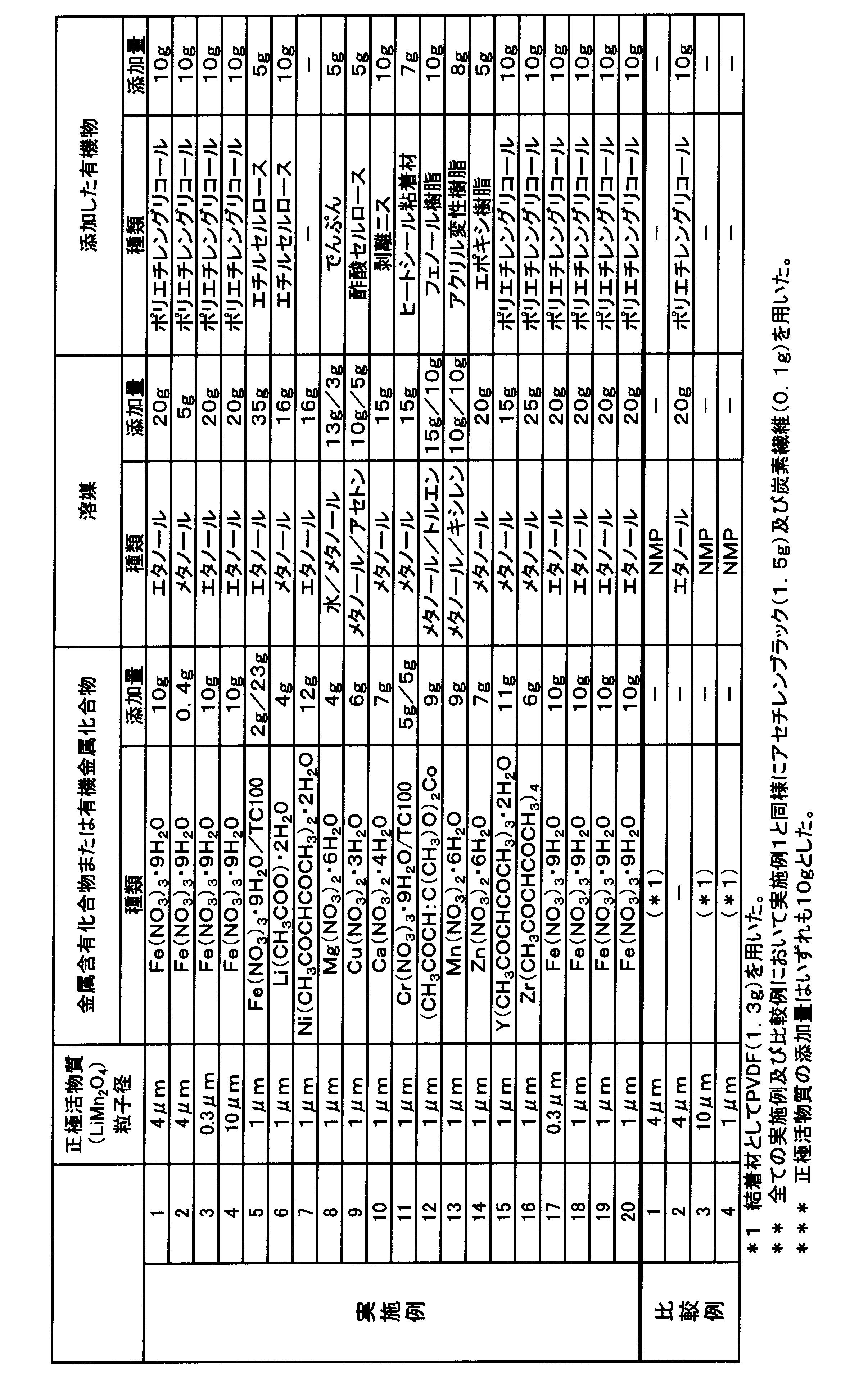

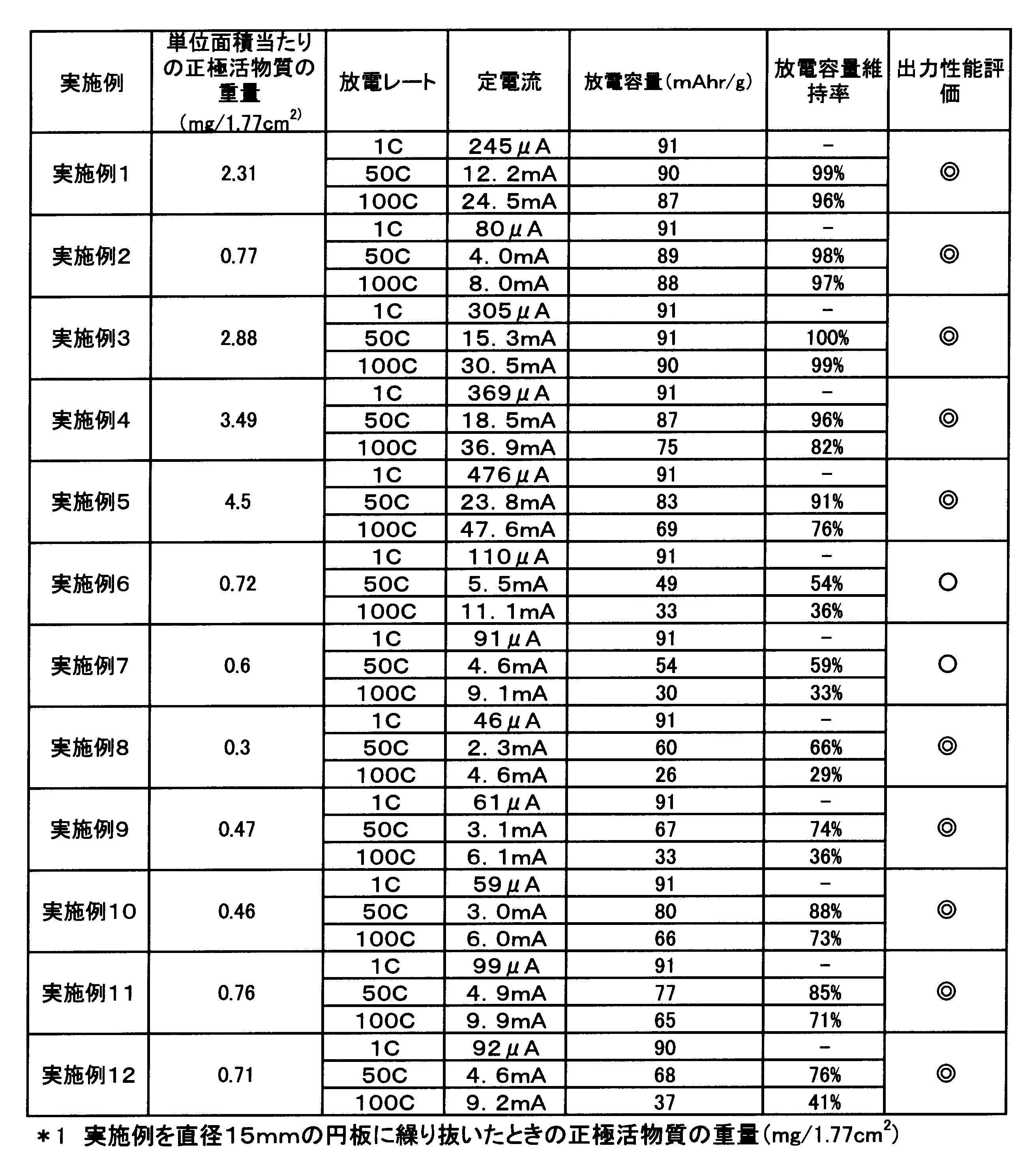
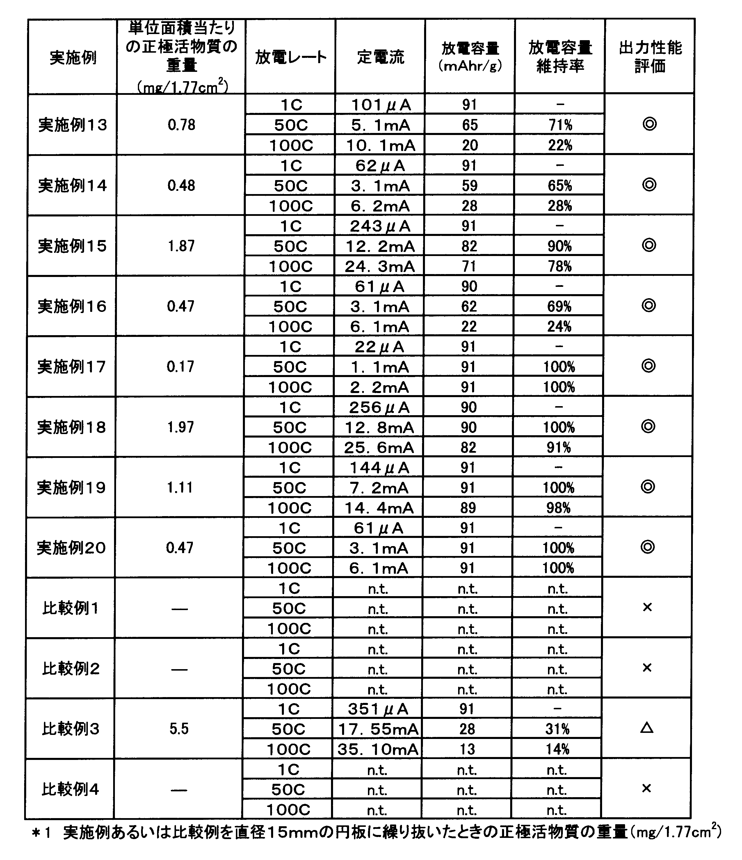

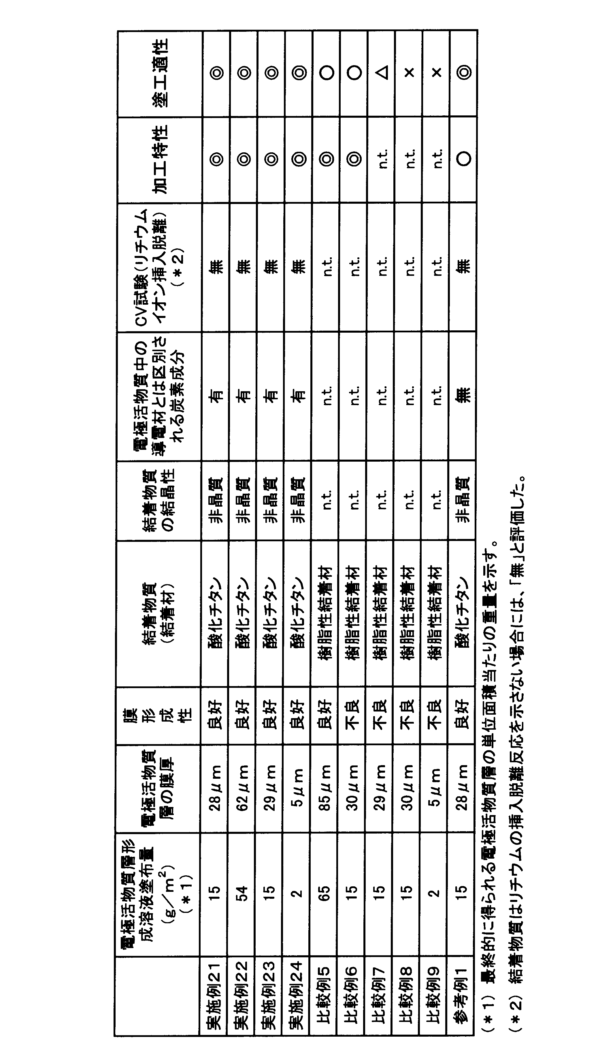
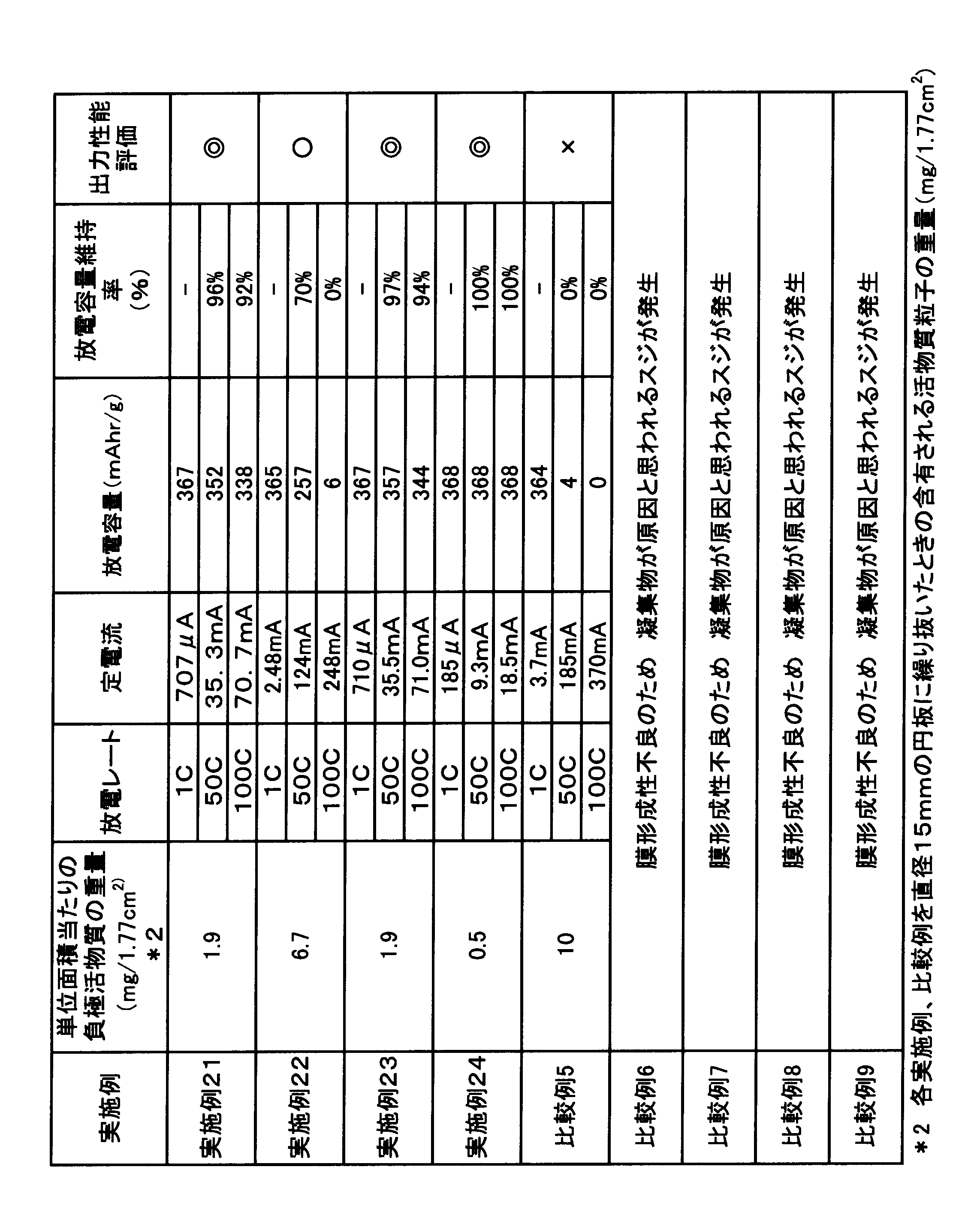
Claims (11)
- 集電体と、
上記集電体の表面の少なくとも一部に形成される電極活物質層と、を備え、
上記電極活物質層は、電極活物質粒子と、結着物質と、導電材とは区別される炭素成分と、を含み、
上記結着物質が、アルカリ金属イオン挿入脱離反応を示さない非晶質の金属酸化物である、非水電解液二次電池用電極板。 - 上記電極活物質層は、導電材をさらに含む、請求項1に記載の非水電解液二次電池用電極板。
- 上記金属酸化物が、Na、Mg、Al、Si、K、Ca、Sc、Ti、V、Cr、Mn、Fe、Co、Ni、Cu、Zn、Ga、Rb、Sr、Y、Zr、Nb、Mo、Tc、Ru、Rh、Pd、Ag、Cd、InおよびSnからなる群より選択されるいずれか1種の金属元素を含む金属酸化物、または、上記群より選択される2種以上の金属元素を含む複合金属酸化物である、請求項1に記載の非水電解液二次電池用電極板。
- 上記電極活物質粒子の粒子径が11μm以下である、請求項1に記載の非水電解液二次電池用電極板。
- 正極板と、
負極板と、
上記正極板と上記負極板との間に設けられるセパレータと、
非水溶媒を含む電解液と、を備え、
上記正極板および上記負極板の少なくとも一方が、請求項1に記載の非水電解液二次電池用電極板である、非水電解液二次電池。 - 電極活物質粒子と、結着物質である金属酸化物を生成するための金属元素含有化合物と、導電材とは区別される炭素成分を付与可能である有機物と、を少なくとも含む電極活物質層形成組成物を、集電体上の少なくとも一部に塗布して塗膜を形成する塗布工程と、
上記塗布工程後に実施される加熱工程であって、上記塗膜を加熱して溶媒を蒸発させるとともに、上記金属元素含有化合物を熱分解して金属酸化物を生成することによって、上記集電体上に金属酸化物と上記電極活物質粒子とを含む電極活物質層を形成する加熱工程と、を含み、
上記加熱工程において生成される金属酸化物が、アルカリ金属イオン挿入脱離反応を示さない金属酸化物となるよう、上記塗布工程に用いられる上記金属元素含有化合物は選択され、
上記加熱工程において、上記金属元素含有化合物の熱分解開始温度以上であって、上記加熱工程において生成される金属酸化物の結晶化温度未満であり、且つ、上記有機物由来の炭素が電極活物質層中に導電材とは区別される炭素成分として残存可能とする温度で、上記塗膜を加熱する、非水電解液二次電池用電極板の製造方法。 - 上記金属元素含有化合物が、金属塩である、請求項6に記載の非水電解液二次電池用電極板の製造方法。
- 電極活物質粒子と、結着物質である金属酸化物を生成するための有機金属化合物と、を少なくとも含む電極活物質層形成組成物を、集電体上の少なくとも一部に塗布して塗膜を形成する塗布工程と、
上記塗布工程後に実施される加熱工程であって、上記塗膜を加熱して溶媒を蒸発させるとともに、上記有機金属化合物を熱分解して金属酸化物を生成することによって、上記集電体上に金属酸化物と上記電極活物質粒子とを含む電極活物質層を形成する加熱工程と、を含み、
上記加熱工程において生成される金属酸化物が、アルカリ金属イオン挿入脱離反応を示さない金属酸化物となるよう、上記塗布工程に用いられる上記有機金属化合物が選択され、
上記加熱工程において、上記有機金属化合物の熱分解開始温度以上であって、上記加熱工程において生成される金属酸化物の結晶化温度未満であり、且つ、上記有機金属化合物由来の炭素が電極活物質層中に導電材とは区別される炭素成分として残存可能とする温度で、上記塗膜を加熱する、非水電解液二次電池用電極板の製造方法。 - 上記有機金属化合物が、金属塩である、請求項8に記載の非水電解液二次電池用電極板の製造方法。
- 電極活物質粒子と、結着物質である金属酸化物を生成するための有機金属化合物と、導電材とは区別される炭素成分を付与可能である有機物と、を少なくとも含む電極活物質層形成組成物を、集電体上の少なくとも一部に塗布して塗膜を形成する塗布工程と、
上記塗布工程後に実施される加熱工程であって、上記塗膜を加熱して溶媒を蒸発させるとともに、上記有機金属化合物を熱分解して金属酸化物を生成することによって、上記集電体上に金属酸化物と上記電極活物質粒子とを含む電極活物質層を形成する加熱工程と、を含み、
上記加熱工程において生成される金属酸化物が、アルカリ金属イオン挿入脱離反応を示さない金属酸化物となるよう、上記塗布工程に用いられる上記有機金属化合物は選択され、
上記加熱工程において、上記有機金属化合物の熱分解開始温度以上であって、上記加熱工程において生成される金属酸化物の結晶化温度未満であり、且つ、上記有機金属化合物由来の炭素および上記有機物由来の炭素の少なくとも一つが電極活物質層中に導電材とは区別される炭素成分として残存可能とする温度で、上記塗膜を加熱する、非水電解液二次電池用電極板の製造方法。 - 上記有機金属化合物が、金属塩である、請求項10に記載の非水電解液二次電池用電極板の製造方法。
Priority Applications (2)
| Application Number | Priority Date | Filing Date | Title |
|---|---|---|---|
| CN201080018372.7A CN102414878B (zh) | 2009-04-24 | 2010-04-19 | 非水电解液二次电池用电极板、非水电解液二次电池用电极板的制备方法及非水电解液二次电池 |
| US13/265,266 US8394538B2 (en) | 2009-04-24 | 2010-04-19 | Electrode plate for non-aqueous electrolyte secondary battery, method for producing the same, and non-aqueous electrolyte secondary battery |
Applications Claiming Priority (4)
| Application Number | Priority Date | Filing Date | Title |
|---|---|---|---|
| JP2009107179 | 2009-04-24 | ||
| JP2009-107179 | 2009-04-24 | ||
| JP2010024837A JP4924852B2 (ja) | 2009-04-24 | 2010-02-05 | 非水電解液二次電池用電極板の製造方法 |
| JP2010-024837 | 2010-02-05 |
Publications (1)
| Publication Number | Publication Date |
|---|---|
| WO2010122983A1 true WO2010122983A1 (ja) | 2010-10-28 |
Family
ID=43011100
Family Applications (1)
| Application Number | Title | Priority Date | Filing Date |
|---|---|---|---|
| PCT/JP2010/056939 Ceased WO2010122983A1 (ja) | 2009-04-24 | 2010-04-19 | 非水電解液二次電池用電極板、非水電解液二次電池用電極板の製造方法、および非水電解液二次電池 |
Country Status (4)
| Country | Link |
|---|---|
| US (1) | US8394538B2 (ja) |
| JP (1) | JP4924852B2 (ja) |
| CN (1) | CN102414878B (ja) |
| WO (1) | WO2010122983A1 (ja) |
Families Citing this family (5)
| Publication number | Priority date | Publication date | Assignee | Title |
|---|---|---|---|---|
| CN103066331B (zh) * | 2012-11-29 | 2018-06-15 | 湖北龙能新能源科技股份有限公司 | 一种超低温高倍率型锂离子电池的制备方法 |
| TWI533497B (zh) * | 2013-08-28 | 2016-05-11 | Current collection layer structure | |
| JP6092741B2 (ja) * | 2013-09-09 | 2017-03-08 | 国立大学法人名古屋大学 | 電極体の製造方法、および、電極体 |
| CN108767222B (zh) * | 2018-05-25 | 2020-09-04 | 厦门大学 | 一种阳离子掺杂三元正极材料纳米纤维的制备方法 |
| JP7281689B2 (ja) * | 2018-09-05 | 2023-05-26 | パナソニックIpマネジメント株式会社 | 正極活物質およびそれを備えた電池 |
Citations (5)
| Publication number | Priority date | Publication date | Assignee | Title |
|---|---|---|---|---|
| JPH11144736A (ja) * | 1997-11-12 | 1999-05-28 | Mitsubishi Chemical Corp | リチウムイオン電解質電池および該電池の製造方法 |
| JP2000277119A (ja) * | 1999-03-26 | 2000-10-06 | Kyocera Corp | リチウム電池 |
| JP2001508916A (ja) * | 1996-11-13 | 2001-07-03 | 三菱化学株式会社 | リチウムイオン電池およびその製造方法 |
| JP2005078985A (ja) * | 2003-09-02 | 2005-03-24 | Toshiba Battery Co Ltd | 非水系二次電池用電極及びこれを用いたリチウム二次電池。 |
| JP2008517435A (ja) * | 2004-10-21 | 2008-05-22 | エボニック デグサ ゲーエムベーハー | リチウムイオンバッテリー用の無機セパレータ電極ユニット、その製造方法及びリチウムバッテリーにおけるその使用 |
Family Cites Families (30)
| Publication number | Priority date | Publication date | Assignee | Title |
|---|---|---|---|---|
| US4902589A (en) | 1988-06-08 | 1990-02-20 | Moli Energy Limited | Electrochemical cells, electrodes and methods of manufacture |
| JP2960834B2 (ja) | 1993-06-07 | 1999-10-12 | シャープ株式会社 | リチウム二次電池 |
| CA2172266A1 (en) | 1993-09-27 | 1995-04-06 | Denis G. Fauteux | Small particle electrodes by aerosol process |
| JPH10208747A (ja) | 1997-01-29 | 1998-08-07 | Hitachi Ltd | 二次電池および二次電池を利用した組電池と機器システム |
| EP1142834A4 (en) | 1999-11-15 | 2009-06-17 | Mitsubishi Chem Corp | LITHIUM MANGANESE COMPOSITE OXIDE, POSITIVE ELECTRODE MATERIAL FOR LITHIUM SECONDARY ACCUMULATOR, POSITIVE ELECTRODE AND LITHIUM SECONDARY ACCUMULATOR, AND PROCESS FOR THE PREPARATION OF LITHIUM MANGANESE COMPOSITE OXIDE |
| JP2001155739A (ja) | 1999-11-24 | 2001-06-08 | Nissha Printing Co Ltd | 二次電池用正極および二次電池 |
| JP4160271B2 (ja) | 2000-08-21 | 2008-10-01 | 三星エスディアイ株式会社 | リチウム二次電池用の電極及びリチウム二次電池 |
| KR100378014B1 (ko) | 2000-08-21 | 2003-03-29 | 삼성에스디아이 주식회사 | 리튬 이차 전지용 전극 및 리튬 이차 전지 |
| JP4799776B2 (ja) | 2000-08-22 | 2011-10-26 | 富士フイルム株式会社 | 電解質組成物及びそれを用いた電気化学電池 |
| JP3809770B2 (ja) | 2001-02-28 | 2006-08-16 | 財団法人電力中央研究所 | 電池材料の製造方法 |
| JP4392169B2 (ja) | 2001-05-15 | 2009-12-24 | Fdk株式会社 | 非水電解質二次電池及びその正極材料の製造方法 |
| JP2003142101A (ja) | 2001-10-31 | 2003-05-16 | Nec Corp | 二次電池用正極およびそれを用いた二次電池 |
| JP2003317707A (ja) | 2002-04-26 | 2003-11-07 | Matsushita Electric Ind Co Ltd | 非水電解質二次電池用負極とその製造方法 |
| JP4767484B2 (ja) * | 2002-08-08 | 2011-09-07 | パナソニック株式会社 | 非水電解質二次電池用正極活物質の製造法および正極活物質 |
| JP2004103304A (ja) | 2002-09-05 | 2004-04-02 | National Institute Of Advanced Industrial & Technology | 高性能二次電池 |
| EP1547973A4 (en) | 2002-09-05 | 2008-07-30 | Nat Inst Of Advanced Ind Scien | FINE CARBON POWDER WITH METAL OXIDE, METAL-NITRIDE OR METAL CARBIDE COATING, MANUFACTURING METHOD DAF R AND SUPERCONDENSATOR AND SECONDARY BATTERY USING THE FINE CARBON POWDER |
| JP4610213B2 (ja) | 2003-06-19 | 2011-01-12 | 三洋電機株式会社 | リチウム二次電池及びその製造方法 |
| JP4407211B2 (ja) | 2003-09-02 | 2010-02-03 | 日産自動車株式会社 | 非水電解質二次電池 |
| US7687102B2 (en) | 2003-10-23 | 2010-03-30 | Medtronic, Inc. | Methods and apparatus for producing carbon cathodes |
| US20050130042A1 (en) * | 2003-12-11 | 2005-06-16 | Byd America Corporation | Materials for positive electrodes of lithium ion batteries and their methods of fabrication |
| CN1930706A (zh) | 2004-08-17 | 2007-03-14 | 株式会社Lg化学 | 安全性和性能提高的锂二次电池 |
| JP4834975B2 (ja) | 2004-09-30 | 2011-12-14 | 大日本印刷株式会社 | 活物質層用塗工組成物、非水電解液二次電池用電極板、及び非水電解液二次電池 |
| JP4193141B2 (ja) | 2005-03-25 | 2008-12-10 | ソニー株式会社 | リチウム二次電池用負極およびリチウム二次電池、並びにそれらの製造方法 |
| JP2006310010A (ja) | 2005-04-27 | 2006-11-09 | Matsushita Electric Ind Co Ltd | リチウムイオン二次電池 |
| FR2890785A1 (fr) | 2005-09-15 | 2007-03-16 | Batscap Sa | Dispositif de stockage d'energie electrique comprenant une couche barriere de protection du collecteur |
| US20070154807A1 (en) | 2005-12-30 | 2007-07-05 | Yevgen Kalynushkin | Nanostructural Electrode and Method of Forming the Same |
| JP5194709B2 (ja) | 2007-10-19 | 2013-05-08 | 住友電気工業株式会社 | 全固体電池およびその製造方法 |
| JP5262143B2 (ja) | 2008-01-31 | 2013-08-14 | トヨタ自動車株式会社 | 正極体およびその製造方法 |
| JP5293020B2 (ja) | 2008-09-10 | 2013-09-18 | 住友化学株式会社 | 非水電解質二次電池用電極合剤、電極および非水電解質二次電池 |
| JP2010129418A (ja) | 2008-11-28 | 2010-06-10 | Sumitomo Chemical Co Ltd | 無機粒子バインダを用いた電極、及びその製造方法 |
-
2010
- 2010-02-05 JP JP2010024837A patent/JP4924852B2/ja not_active Expired - Fee Related
- 2010-04-19 CN CN201080018372.7A patent/CN102414878B/zh not_active Expired - Fee Related
- 2010-04-19 US US13/265,266 patent/US8394538B2/en not_active Expired - Fee Related
- 2010-04-19 WO PCT/JP2010/056939 patent/WO2010122983A1/ja not_active Ceased
Patent Citations (5)
| Publication number | Priority date | Publication date | Assignee | Title |
|---|---|---|---|---|
| JP2001508916A (ja) * | 1996-11-13 | 2001-07-03 | 三菱化学株式会社 | リチウムイオン電池およびその製造方法 |
| JPH11144736A (ja) * | 1997-11-12 | 1999-05-28 | Mitsubishi Chemical Corp | リチウムイオン電解質電池および該電池の製造方法 |
| JP2000277119A (ja) * | 1999-03-26 | 2000-10-06 | Kyocera Corp | リチウム電池 |
| JP2005078985A (ja) * | 2003-09-02 | 2005-03-24 | Toshiba Battery Co Ltd | 非水系二次電池用電極及びこれを用いたリチウム二次電池。 |
| JP2008517435A (ja) * | 2004-10-21 | 2008-05-22 | エボニック デグサ ゲーエムベーハー | リチウムイオンバッテリー用の無機セパレータ電極ユニット、その製造方法及びリチウムバッテリーにおけるその使用 |
Also Published As
| Publication number | Publication date |
|---|---|
| JP2010272509A (ja) | 2010-12-02 |
| US8394538B2 (en) | 2013-03-12 |
| CN102414878A (zh) | 2012-04-11 |
| US20120040250A1 (en) | 2012-02-16 |
| CN102414878B (zh) | 2014-06-18 |
| JP4924852B2 (ja) | 2012-04-25 |
Similar Documents
| Publication | Publication Date | Title |
|---|---|---|
| JP5136804B2 (ja) | 非水電解液二次電池用電極板、非水電解液二次電池用電極板の製造方法、および非水電解液二次電池 | |
| JP5196197B2 (ja) | 非水電解液二次電池用電極板の製造方法 | |
| JP5212394B2 (ja) | 非水電解液二次電池用電極板の製造方法 | |
| JP4924852B2 (ja) | 非水電解液二次電池用電極板の製造方法 | |
| JP2012079651A (ja) | 非水電解液二次電池用電極板、非水電解液二次電池、および電池パック | |
| JP2011100747A (ja) | 非水電解液二次電池用電極板、非水電解液二次電池用電極板の製造方法、および非水電解液二次電池 | |
| JP2012094361A (ja) | 非水電解液二次電池用電極板、非水電解液二次電池および電池パック | |
| JP2011100748A (ja) | 非水電解液二次電池用電極板、非水電解液二次電池用電極板の製造方法、および非水電解液二次電池 | |
| JP2011204489A (ja) | 非水電解液二次電池用正極板、非水電解液二次電池用正極板の製造方法、および非水電解液二次電池 | |
| JP2012094338A (ja) | 非水電解液二次電池用電極板、非水電解液二次電池、及び電池パック | |
| JP2012084423A (ja) | 非水電解液二次電池用電極板、非水電解液二次電池、および電池パック | |
| JP2011204488A (ja) | 非水電解液二次電池用正極板、非水電解液二次電池用正極板の製造方法、および非水電解液二次電池 | |
| JP2011204490A (ja) | 非水電解液二次電池用正極板、非水電解液二次電池用正極板の製造方法、および非水電解液二次電池 | |
| JP2011204460A (ja) | 非水電解液二次電池用正極板、非水電解液二次電池用正極板の製造方法、および非水電解液二次電池 | |
| WO2011030846A1 (ja) | 非水電解液二次電池用電極板、非水電解液二次電池用電極板の製造方法、非水電解液二次電池、および電池パック | |
| JP2011210537A (ja) | 非水電解液二次電池用電極板、非水電解液二次電池用電極板の製造方法、および非水電解液二次電池 | |
| JP2011204459A (ja) | 非水電解液二次電池用正極板、非水電解液二次電池用正極板の製造方法、および非水電解液二次電池 | |
| JP2011204470A (ja) | 非水電解液二次電池用正極板、非水電解液二次電池用正極板の製造方法、および非水電解液二次電池 | |
| JP2011204491A (ja) | 非水電解液二次電池用正極板、非水電解液二次電池用正極板の製造方法、および非水電解液二次電池 | |
| JP2011204458A (ja) | 非水電解液二次電池用正極板、非水電解液二次電池用正極板の製造方法、および非水電解液二次電池 | |
| JP2012089275A (ja) | 非水電解液二次電池用電極板、非水電解液二次電池用電極板の製造方法、非水電解液二次電池、および電池パック | |
| JP2012089274A (ja) | 非水電解液二次電池用電極板、非水電解液二次電池用電極板の製造方法、非水電解液二次電池、および電池パック | |
| JP2012089272A (ja) | 非水電解液二次電池用電極板、非水電解液二次電池用電極板の製造方法、非水電解液二次電池、および電池パック | |
| JP2012074227A (ja) | 非水電解液二次電池用電極板、非水電解液二次電池および電池パック | |
| JP2012094334A (ja) | 非水電解液二次電池用正極板、非水電解液二次電池、電池パック、非水電解液二次電池用正極板の製造方法、および正極用電極活物質層の形成方法 |
Legal Events
| Date | Code | Title | Description |
|---|---|---|---|
| WWE | Wipo information: entry into national phase |
Ref document number: 201080018372.7 Country of ref document: CN |
|
| 121 | Ep: the epo has been informed by wipo that ep was designated in this application |
Ref document number: 10767040 Country of ref document: EP Kind code of ref document: A1 |
|
| WWE | Wipo information: entry into national phase |
Ref document number: 13265266 Country of ref document: US |
|
| NENP | Non-entry into the national phase |
Ref country code: DE |
|
| 122 | Ep: pct application non-entry in european phase |
Ref document number: 10767040 Country of ref document: EP Kind code of ref document: A1 |