WO2010122602A1 - 高電圧装置、およびそれを備えた放射線源、放射線透視撮影装置 - Google Patents
高電圧装置、およびそれを備えた放射線源、放射線透視撮影装置 Download PDFInfo
- Publication number
- WO2010122602A1 WO2010122602A1 PCT/JP2009/001836 JP2009001836W WO2010122602A1 WO 2010122602 A1 WO2010122602 A1 WO 2010122602A1 JP 2009001836 W JP2009001836 W JP 2009001836W WO 2010122602 A1 WO2010122602 A1 WO 2010122602A1
- Authority
- WO
- WIPO (PCT)
- Prior art keywords
- voltage
- anode
- rotating anode
- rotating
- time
- Prior art date
- Legal status (The legal status is an assumption and is not a legal conclusion. Google has not performed a legal analysis and makes no representation as to the accuracy of the status listed.)
- Ceased
Links
Images



Classifications
-
- H—ELECTRICITY
- H05—ELECTRIC TECHNIQUES NOT OTHERWISE PROVIDED FOR
- H05G—X-RAY TECHNIQUE
- H05G1/00—X-ray apparatus involving X-ray tubes; Circuits therefor
- H05G1/08—Electrical details
- H05G1/10—Power supply arrangements for feeding the X-ray tube
-
- H—ELECTRICITY
- H01—ELECTRIC ELEMENTS
- H01J—ELECTRIC DISCHARGE TUBES OR DISCHARGE LAMPS
- H01J35/00—X-ray tubes
- H01J35/24—Tubes wherein the point of impact of the cathode ray on the anode or anticathode is movable relative to the surface thereof
- H01J35/26—Tubes wherein the point of impact of the cathode ray on the anode or anticathode is movable relative to the surface thereof by rotation of the anode or anticathode
-
- H—ELECTRICITY
- H05—ELECTRIC TECHNIQUES NOT OTHERWISE PROVIDED FOR
- H05G—X-RAY TECHNIQUE
- H05G1/00—X-ray apparatus involving X-ray tubes; Circuits therefor
- H05G1/08—Electrical details
- H05G1/26—Measuring, controlling or protecting
- H05G1/30—Controlling
- H05G1/32—Supply voltage of the X-ray apparatus or tube
-
- H—ELECTRICITY
- H05—ELECTRIC TECHNIQUES NOT OTHERWISE PROVIDED FOR
- H05G—X-RAY TECHNIQUE
- H05G1/00—X-ray apparatus involving X-ray tubes; Circuits therefor
- H05G1/08—Electrical details
- H05G1/26—Measuring, controlling or protecting
- H05G1/30—Controlling
- H05G1/38—Exposure time
-
- H—ELECTRICITY
- H05—ELECTRIC TECHNIQUES NOT OTHERWISE PROVIDED FOR
- H05G—X-RAY TECHNIQUE
- H05G1/00—X-ray apparatus involving X-ray tubes; Circuits therefor
- H05G1/08—Electrical details
- H05G1/26—Measuring, controlling or protecting
- H05G1/30—Controlling
- H05G1/46—Combined control of different quantities, e.g. exposure time as well as voltage or current
Definitions
- the present invention relates to a high-voltage device that supplies power to a radiation source capable of changing the radiation intensity, and a radiation source and a radiographic imaging device including the same.
- a medical institution is equipped with a radiographic imaging apparatus that acquires a fluoroscopic image of a subject.
- a conventional configuration in such a radiographic imaging apparatus will be described.
- a conventional radiographic imaging apparatus includes a top plate on which a subject is placed, a radiation source provided above the top plate, and radiation detection means (FPD) provided below the top plate.
- the radiation source and the FPD are movable along the body axis direction of the subject M.
- the radiation source 53 has a disk-shaped rotating anode 61 whose periphery is tapered.
- the rotary anode 61 is located in the hollow portion of the vacuum vessel 62, and is maintained in a vacuum.
- the support shaft 63 rotatably supports the rotary anode 61.
- the cathode 64 is installed at a position facing the periphery of the rotary anode 61, and irradiates electrons E toward the periphery of the rotary anode 61 from here. At this time, a high voltage is applied between the rotary anode 61 and the cathode 64.
- a radiation source having such a configuration is described in Patent Document 1, for example.
- the voltage applied between the rotary anode 61 and the cathode 64 is supplied from a voltage application unit 67.
- the rotating mechanism 65 that rotates the support shaft 63 is provided for the purpose of rotating the rotating anode 61 relative to the cathode 64.
- the input unit 80 allows an operator's instruction to be input. Through this, the operator can freely operate the radiation source 53.
- the main control unit 81 comprehensively controls each part of the X-ray tube.
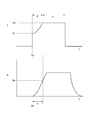
- the rotation anode 61 starts rotating at the time TA, and the rotation speed R of the rotation anode 61, which was initially 0, increases.
- the voltage application unit 67 is first applied between the electrodes 61 and 64 with a minimum voltage VL that is low enough to prevent damage even if the rotary anode 61 is stationary.
- the rotary anode 61 When the rotation of the rotary anode 61 is started, the rotary anode 61 is eventually set to a predetermined rotation number RA. However, at the time point TA, the rotating anode is stationary, and some time is required until the rotating speed RA is reached. This required time is assumed to be t1.
- the lowest voltage VL (for example, 50 kV) is applied to the electrodes 61 and 64 at the time TA. At the same time as the speed of the rotating anode 61 increases, the voltage applied to the electrodes 61 and 64 is gradually increased.
- the voltage applied to the electrodes 61 and 64 is finally a voltage VA suitable for diagnosis (for example, 80 kV).
- VA suitable for diagnosis for example, 80 kV
- E the period during which the voltage applied to the electrodes 61 and 64 reaches the voltage VA suitable for diagnosis from VL.
- This voltage control is performed by an ABC (automatic brightness controller) 70 that adjusts the brightness of the fluoroscopic image by automatically changing the radiation intensity.
- the conventional radiation source has the following problems. That is, in the radiation source of the conventional configuration, when starting the fluoroscopy from a state where the rotating anode is stationary, when radiation irradiation is started, the voltage applied to the electrodes 61 and 64 is first started from the lowest voltage VL, Then, it is raised to a voltage VA suitable for diagnosis.
- the intensity of the radiation is desired by the surgeon when a voltage VA suitable for diagnosis is applied to the bipolar electrodes 61 and 64. That is, the intensity of the radiation emitted from the radiation source is weak until the voltage applied to the electrodes 61 and 64 reaches the voltage VA suitable for diagnosis. That is, radiation irradiated with a voltage lower than the voltage VA suitable for diagnosis cannot be used for diagnosis. Eventually, it is necessary to wait until the voltage applied to both electrodes 61 and 64 becomes a voltage VA suitable for diagnosis.
- a fluoroscopic image suitable for diagnosis is obtained only during the period P in FIG. That is, unnecessary radiation advances to the subject M during the period E in FIG. From the viewpoint of suppressing the exposure amount of the subject M, it is desirable that the radiation source is irradiated only while obtaining a fluoroscopic image suitable for diagnosis. Unnecessary exposure in the period E is Should be suppressed.
- the present invention has been made in view of such circumstances, and an object of the present invention is to provide a high-voltage device capable of suppressing radiation exposure to a subject, a radiation source including the same, and a radiographic imaging device. It is to provide.
- the high voltage device applies a voltage to a radiation source including a rotating anode, a container including the rotating anode, a rotating means for rotating the rotating anode, and a rotation control means for controlling the rotating anode.
- a voltage applying means for applying a voltage to the rotating anode, and a predetermined voltage capable of radiographic imaging is applied to the voltage applying means when the rotating anode reaches a high rotational speed so as not to damage Voltage application instruction means for instructing to do so.
- a predetermined voltage is applied to the rotating anode after waiting for the rotating anode to have a rotational speed high enough not to damage the rotating anode.
- a fluoroscopic image suitable for diagnosis can be obtained immediately after the voltage is applied to the rotating anode.
- the invention according to claim 2 is the high voltage device according to claim 1, wherein the voltage application instructing means is high enough not to be damaged even if a voltage is applied to the rotating anode after the rotation of the rotating anode is started.
- the rotation speed is reached, an instruction is given to apply a voltage.
- the voltage application instructing means (A) starts rotating the rotating anode based on the current and voltage applied to the rotating anode. It is characterized in that the period until the rotation speed is high enough not to be damaged even if is applied is determined.
- the voltage application instructing means is such that the rotary anode is not damaged even if the voltage is applied to the rotary anode from the time when the voltage application is completed.
- a delay time indicating a period of high rotation speed has elapsed, an instruction is given to apply a voltage
- the voltage application instruction means includes (A) current and voltage applied to the rotating anode, and (B) rotating anode.
- the delay time is determined based on the deviation time from the end of voltage application to the start of braking of the rotation of the rotating anode.
- the above-described configuration is a specific example of how the voltage application instruction means determines that the number of rotations of the rotating anode has increased sufficiently. That is, the voltage application instructing means determines that the rotation speed at which the rotary anode is not damaged has been reached when a certain period has elapsed since the rotation of the stopped rotary anode is started. Further, the voltage application support means determines that the rotational speed has reached a value at which the rotary anode is not damaged when the delay time has elapsed since the voltage application to the rotary anode has been completed.
- This delay time may be variable according to the applied load.
- the invention according to claim 4 is the high voltage device according to any one of claims 1 to 3, further comprising a rotation speed measuring means for measuring the rotation speed of the rotating anode, wherein the voltage application instruction means is: It is characterized in that an instruction is given to apply a voltage when the measured number of revolutions is higher than the number of revolutions that is high enough not to damage the rotating anode even when a voltage is applied.
- the above-described configuration is one specific example of how the voltage application instruction means determines that the number of rotations of the rotating anode has increased sufficiently. That is, the voltage application instructing means determines that the rotational speed at which the rotating anode is not damaged is reached when the rotational speed of the rotating anode actually measured by the rotational speed measuring means is equal to or higher than a predetermined rotational speed. If the rotational speed is equal to or higher than the predetermined rotational speed (allowable rotational speed), it can be said that the rotational speed of the rotating anode has increased sufficiently. Even if a predetermined voltage is applied between the rotating anode and the cathode, the rotating anode There is no damage. This allowable rotational speed may be variable according to the applied load.
- the invention according to claim 5 is the high-voltage device according to claim 3, further comprising input means for inputting an operator's instruction, wherein the voltage application instruction means is a voltage applied to the previous rotating anode by the operator. After the instruction to end the application, when the rotation speed is maintained high enough not to damage the rotating anode, the instruction is given to apply the voltage.
- the above-described configuration is one specific example of how the voltage application instruction means determines that the number of rotations of the rotating anode has increased sufficiently. After a certain amount of time has elapsed after irradiation, the rotating anode is braked and decelerated, and after a few minutes, the rotating anode stops completely. . When the rotational speed of the rotating anode is kept sufficiently high, voltage can be immediately applied between the rotating anode and the cathode without waiting for a delay time from the start of rotation.
- the voltage application instructing means in the above-described configuration determines that the number of revolutions has reached a value that does not damage the rotating anode even before the delay time has elapsed since the rotation of the rotating anode has started. This improves the response of the radiation source to the surgeon's input.
- This allowable time may be variable depending on the applied load.
- the present invention further includes a set value storage unit that stores a set value that is referred to by the voltage application instruction unit. , Which can be changed.
- the rotating anode, a container including the rotating anode, and the rotating anode are rotated.
- Rotating means and rotation control means for controlling the rotating anode are provided.
- a radiation source capable of outputting radiation having a desired intensity from the start of irradiation can be provided.
- the invention according to claim 8 is characterized in that in the radiographic imaging apparatus having the radiation source according to claim 7, radiation detecting means for detecting radiation irradiated from the radiation source is provided. .
- Radiographic imaging apparatus including a radiation source capable of outputting radiation having a desired intensity from the start of irradiation. Since the subject is not exposed to radiation exposure that cannot be used for diagnosis, a radiographic imaging apparatus in which radiation exposure to the subject is suppressed can be provided.
- FIG. 3 is a functional block diagram illustrating the configuration of the X-ray tube according to Embodiment 1.
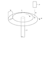
- FIG. 3 is a perspective view illustrating the configuration of a rotating anode according to Example 1.
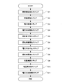
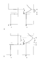
- FIG. 3 is a flowchart for explaining the operation of the X-ray tube according to Embodiment 1; 3 is a timing chart for explaining the operation of the X-ray tube according to Embodiment 1; 3 is a timing chart for explaining the operation of the X-ray tube according to Embodiment 1;
- It is a functional block diagram explaining the structure of the X-ray tube which concerns on Example 2.
- FIG. It is a functional block diagram explaining the structure of the X-ray tube which concerns on Example 2.
- FIG. 6 is a timing chart illustrating the configuration of a radiation source according to Example 2.
- Rotating anode Vacuum container (container) 3 Support shaft 4 Cathode 5 Rotating mechanism (Rotating means) 6 Rotation control unit (rotation control means) 7 Voltage application part (voltage application means) 8 Voltage application instruction section (voltage application instruction means) 9 Rotational speed measuring unit (Rotational speed measuring means) 10 X-ray tube (radiation source) 22 set value storage unit (set value storage means) 34 FPD (radiation detection means)
- X-rays are an example of radiation according to the present invention.
- FIG. 1 is a perspective view illustrating the configuration of the rotating anode according to the first embodiment.
- the rotary anode 1 is rotatably supported by a support shaft 3.
- the rotary anode 1 has a disc shape and a tapered shape that tapers along a direction away from the support shaft 3. That is, the rotary anode 1 has an umbrella shape, and the peripheral edge 1 a (see FIG. 2) is inclined with respect to the support shaft 3.
- the peripheral edge 1a is also called an electron beam target.
- the vacuum container corresponds to the container of the present invention
- the X-ray tube corresponds to the radiation source of the present invention.
- the tip of the cathode 4 is located in the hollow part 2 a of the vacuum vessel 2 and faces the peripheral part 1 a of the rotary anode 1.
- a voltage is applied to the rotating anode 1 and the cathode 4
- electrons E are irradiated from the tip of the cathode 4 toward the peripheral edge 1 a of the rotating anode 1.
- the electrons E emitted from the cathode 4 hit the peripheral edge 1 a of the rotating anode 1, from which the X-ray beam B is irradiated toward the outside of the vacuum vessel 2.
- the tip of the cathode 4 is a filament that emits electrons.
- High voltage applied to the rotary anode 1 and the cathode 4 is supplied from the voltage application unit 7.
- the voltage supplied from the voltage application unit 7 is variable.
- the voltage application instructing unit 8 sends an instruction signal to the voltage applying unit 7, and the voltage applying unit 7 stops applying the voltage between the rotating anode 1 and the cathode 4 or resumes applying the voltage in accordance with this instruction signal.
- the voltage application unit corresponds to the voltage application unit of the present invention
- the voltage application instruction unit corresponds to the voltage application instruction unit of the present invention.
- the cathode heating current supply unit 17 supplies a low voltage current to the cathode 4. This current passes through the coiled cathode 4 and heats the cathode 4. That is, in the X-ray tube 10, the cathode 4 is heated before generating X-rays. The heated cathode 4 is likely to cause thermionic emission. In this state, when a voltage higher than the voltage application unit 7 is applied to the two electrodes 1 and 4, electrons E jump out one after another from the cathode 4 toward the rotating anode 1. It will be.
- the cathode heating current supply unit 17 is controlled by the cathode heating current control unit 12.
- the rotation mechanism 5 for rotating the support shaft 3 is provided for the purpose of rotating the rotating anode 1 with respect to the cathode 4.
- the rotation mechanism 5 is controlled by the rotation control unit 6.
- the input unit 21 allows an operator's instruction to be input. Through this, the operator can perform an instruction to start fluoroscopy and change X-ray conditions.
- the insulating ring 3 a is a bearing for the support shaft 3.
- the insulating ring 3 a insulates the support shaft 3 from the vacuum vessel 2 and prevents air from flowing from the outside of the vacuum vessel 2 toward the hollow portion 2 a that is in a vacuum.
- the rotation control unit corresponds to the rotation control unit of the present invention, and the rotation mechanism corresponds to the rotation unit of the present invention.
- the rotation speed measurement unit 9 sequentially monitors the rotation speed of the rotary anode 1.
- the rotational speed measurement unit 9 sends the rotational speed data to a main control unit 29 described later.
- the rotational speed measuring unit corresponds to the rotational speed measuring means of the present invention.
- Each of the set voltage value storage unit 22, the delay time storage unit 23, and the allowable value storage unit 24 is a storage unit that stores a set voltage value Va, a delay time D, and an allowable time AT, which will be described later.
- the X-ray tube 10 is provided with a time difference acquisition unit 18. The significance of providing these will be described later. The surgeon can update the set voltage Va stored in the set voltage value storage unit 22 through the input unit 21.
- the X-ray tube 10 is provided with a main control unit 29 that comprehensively controls each of the rotation control unit 6, the voltage application instruction unit 8, and the cathode heating current control unit 12.
- the main control unit 29 is configured by a CPU, and realizes each unit by executing various programs. Further, each of the above-described units may be divided and executed by an arithmetic device that takes charge of them.
- FIG. 3 is a flowchart for explaining the operation of the X-ray tube according to the first embodiment.
- a series of operations incorporating features of the operation of the X-ray tube 10 according to the first embodiment will be described. That is, an operation example of the X-ray tube 10 described below includes an irradiation start instruction step S1 in which an instruction to start irradiation is input to the input unit 21, a rotation start step S2 to start rotation of the rotary anode 1, and voltage application.
- ⁇ Irradiation start instruction step S1, rotation start step S2> First, the surgeon instructs the X-ray tube 10 to irradiate X-rays through the input unit 21. Then, the rotation control unit 6 immediately gives an instruction to start the rotation of the rotary anode 1, and the rotation of the rotary anode 1 that has stopped rotating is started.
- ⁇ Voltage control step S3> the voltage of the voltage application unit 7 is adjusted by the voltage control unit 8. That is, the voltage control unit 8 reads the set voltage value Va stored in the set voltage value storage unit 22 and sets the voltage of the voltage application unit 7 as Va. At this time, the voltage application instructing unit 8 has not instructed the voltage applying unit 7 to apply a voltage, so that the voltage application to the bipolar electrodes 1 and 4 by the voltage applying unit 7 remains suspended.
- the operator may instruct change of the set voltage value Va before instructing X-ray irradiation.
- the voltage control unit 8 uses the voltage application unit 7 based on the new set voltage value Vb. Will be controlled.
- the cathode heating current supply unit 17 is controlled by the cathode heating current control unit 12, and heating of the cathode 4 is started.
- the voltage application instruction unit 8 reads the period N stored in the delay time storage unit 23.
- This period N is, for example, 0.5 seconds.
- a value calculated by the main control unit 29 according to the load by the set voltage value Va or Vb may be used as the period N.
- a method for calculating the period N will be described later.
- the voltage application instructing unit 8 gives an instruction to start voltage application to the voltage applying unit 7 after a certain period N has elapsed from the point St when the X-ray irradiation instruction is given. In this way, the set voltage Va is applied to the two electrodes 1 and 4, and X-rays are emitted from the X-ray tube 10.
- the voltage application instruction unit 8 is configured to instruct voltage application based on the period N.
- the period N indicates a period from the start of rotation of the rotating anode 1 that has stopped rotating until the rotating anode 1 reaches a high rotational speed that does not damage even when a voltage is applied.
- the voltage application start step S4 will be described in more detail with reference to FIG.
- the rotation of the rotary anode 1 is immediately started.
- the rotation of the rotary anode 1 is not sufficiently increased. If a high voltage is applied to the electrodes 1 and 4 from this time point, the rotary anode 1 may be damaged. Therefore, according to the configuration of the first embodiment, a high voltage is applied to the two poles 1 and 4 at the time point Dt after the period N has elapsed from the time point St. Since the rotational speed of the rotary anode 1 is sufficiently increased at the time point Dt, the rotary anode 1 is not damaged.
- the X-ray intensity is weak at the start of X-ray irradiation.
- the X-ray intensity at the start time Dt of X-ray irradiation is The person who wants it. This is because the set voltage Va is applied to the two poles 1 and 4 at the time point Dt. That is, the period P in which X-rays having an intensity suitable for diagnosis is irradiated starts from the time point Dt in FIG. That is, diagnosis can be started simultaneously with the start of X-ray irradiation.
- the arrow of FIG.4 (b) represents the time (time of step S5) when the surgeon gave the instruction
- X-ray irradiation is stopped as soon as the end of X-ray irradiation is instructed.
- the rotation of the rotating anode 1 has a margin, and the braking of the rotation is applied after a predetermined deviation time Q has elapsed since the X-ray irradiation was stopped.
- a time point at which braking of the rotating anode 1 starts to be applied is defined as a time point Ft.
- the time between the time point Ft and the time point Gt (hereinafter referred to as the inter-instruction time FG) is calculated by the time difference acquisition unit 18. Then, the voltage application instruction unit 8 reads the allowable time AT stored in the allowable value storage unit 24, and compares the inter-instruction time FG with the allowable time AT. As shown in FIG. 4B, when the inter-instruction time FG is shorter than the allowable time AT, the voltage application instructing unit 8 instructs the voltage application. In this way, X-rays are immediately re-irradiated when an instruction to resume X-ray irradiation is given.
- the allowable time AT is, for example, 5 minutes.
- the voltage application instruction unit 8 is configured to instruct voltage application based on the allowable time AT.
- the time from the end of X-ray irradiation to the resumption of X-ray irradiation is the delay time D.
- the delay time D is shorter than the sum of the deviation time Q and the allowable time AT.
- the allowable time AT is as follows. That is, when the time from the end of the previous voltage application to the rotating anode 1 to the time when an instruction to start radiation irradiation is input to the input means is shorter than the allowable time AT, the rotating anode 1 It is in the state which maintained high rotation speed to such an extent that it was not damaged even if it applied.
- the rotation speed of the rotary anode 1 is sufficiently high, and even if a high voltage is applied to both electrodes 1 and 4, the rotary anode 1 can be damaged. Absent.
- the voltage of the voltage application unit 7 is Va
- the voltage Va is applied to the bipolar electrodes 1 and 4 at the time point Gt when the surgeon instructs to resume the X-ray irradiation. That is, the period P during which X-rays having an intensity suitable for diagnosis is irradiated starts from the time point Gt. That is, the surgeon can obtain an X-ray fluoroscopic image suitable for diagnosis at the same time when X-ray irradiation is resumed.
- the inter-instruction time FG is equal to or longer than the allowable time AT.
- the rotation speed of the rotating anode 1 is slow. If a high voltage is applied to the electrodes 1 and 4 as they are, the rotating anode 1 may be damaged. There is sex. Therefore, when the inter-instruction time FG is equal to or greater than the allowable time AT, the voltage application instructing unit 8 does not immediately apply a high voltage to the electrodes 1 and 4. As shown in FIG. 5A, the voltage application instructing unit 8 instructs voltage application after the delay time D has elapsed from the time Et at which X-ray irradiation ends.
- the delay time D is equal to or longer than the sum of the deviation time Q and the allowable time AT.
- the rotational speed of the rotating anode 1 is sufficiently increased, and the rotating anode 1 is not damaged. .
- the voltage Va is applied to the electrodes 1 and 4 from the time when the X-rays are re-irradiated. Therefore, the operator can obtain an X-ray fluoroscopic image suitable for diagnosis at the same time as the X-ray irradiation is resumed.
- the set voltage value Va can be changed when the X-rays are re-irradiated. That is, if the surgeon gives an instruction to change the set voltage value from Va to Vb before giving an instruction to restart the X-ray irradiation through the input unit 21, as shown in FIG. The line irradiation is resumed by applying a voltage of Vb to both electrodes 1 and 4.
- the voltage application unit 7 reads the set voltage value from the set voltage value storage unit 22 before the voltage application instruction unit 8 gives the voltage application unit 7 an instruction to resume the voltage application.
- the damage limit load maximum load at which damage starts to occur in a state where the rotating anode 1 is stopped is 2 kW.
- the damage limit load when the rotating anode 1 is rotated at 60 Hz is 20 kW.
- the rotary anode 1 Since the rotary anode 1 increases by 20 Hz per second from the stopped state, it takes about 0.3 seconds for the rotation speed of the rotation anode 1 to increase from the rotation start to the rotation speed r.
- the safety factor of 1.3 is considered to be about 0.4 seconds. That is, when the load of the rotary anode 1 is 8 kW, the period N is about 0.4 seconds. If the rotational speed increase rate of the rotating anode 1 is v (Hz / sec), the period N and the delay time D are generally obtained as follows. N> r / v D> r / v + Q
- Q is the above-described deviation time.
- the voltage application instruction unit 8 calculates the period N and the delay time D. Therefore, the data relating to the tube voltage and the tube current and the data relating to the time when each operation is performed are sequentially sent to the voltage application instructing unit 8.
- a predetermined voltage is applied to the bipolar electrodes 1 and 4 after waiting until the rotational speed becomes high enough not to damage the rotating anode 1. That is, X-rays having a desired intensity are already output from the time when the voltage is applied to both poles 1 and 4. Therefore, an X-ray fluoroscopic image can be acquired immediately after the voltage is applied to both electrodes 1 and 4. That is, it is not necessary to wait until the X-ray intensity becomes suitable for diagnosis after the X-ray irradiation is started as in the prior art, and it is not necessary to irradiate the subject M with X-rays that cannot be used for diagnosis. Therefore, unnecessary X-rays can be prevented from being irradiated to the subject M.
- the voltage application instructing unit 8 determines that the rotational speed of the rotary anode 1 has sufficiently increased is as follows. That is, the voltage application instructing unit 8 determines that the rotational speed at which the rotating anode 1 is not damaged is reached when the rotation of the rotating anode 1 in the stopped state has passed the period N or the delay time D from the start. If the period N or the delay time D has elapsed, it can be said that the rotational speed of the rotating anode 1 has sufficiently increased. Therefore, even if a predetermined voltage is applied to the electrodes 1 and 4, the rotating anode 1 is not damaged.
- the rotary anode 1 continues to rotate for a while after the X-ray irradiation is finished and braking is applied. In this state, when the rotational speed of the rotating anode 1 is kept sufficiently high, it is possible to immediately apply a voltage to the electrodes 1 and 4 without waiting for the delay time D from the start of the rotation.
- the time from when the previous voltage application to the bipolar electrodes 1 and 4 is completed to when the instruction to start X-ray irradiation is input to the input unit is shorter than the predetermined allowable time AT, The rotational speed of the rotary anode 1 is sufficiently high so as not to cause damage.
- the voltage application instructing unit 8 determines in this case that the number of revolutions has reached a value at which the rotary anode 1 is not damaged even before the delay time D has elapsed from the start of the rotation of the rotary anode 1. . This improves the response of the X-ray source to the surgeon's input.
- the X-ray tube 10 that can be freely handled by changing the inspection method or the like can be provided. That is, since the surgeon can change the set voltage value Va as desired, the voltage applied to the rotary anode 1 is surely desired by the surgeon from the point of application.
- Example 2 is an example of the radiation of this invention.
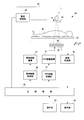
- FIG. 6 is a functional block diagram illustrating the configuration of the X-ray imaging apparatus according to the second embodiment.
- the X-ray fluoroscopic apparatus 30 according to the second embodiment includes a top plate 32 on which the subject M is placed, and a pulsed X-ray beam provided on the top plate 32.
- an X-ray grid 35 for removing scattered X-rays incident on the.
- the configuration of the second embodiment includes a tube control unit 36 that controls the tube voltage, tube current, and time pulse width of the X-ray beam of the X-ray tube 10, and a tube moving mechanism that moves the X-ray tube 10. 37 and a tube movement control unit 38 for controlling this.
- the X-ray fluoroscopic apparatus 30 according to the second embodiment includes an FPD moving mechanism 31 that moves the FPD 34 and an FPD movement control unit 32 that controls the FPD moving mechanism 31.
- the X-ray fluoroscopic apparatus 30 includes an image generation unit 42 that generates an X-ray fluoroscopic image based on the detection data output from the FPD 34.
- the X-ray tube corresponds to the radiation source of the present invention
- the FPD corresponds to the radiation detection means of the present invention.
- the X-ray fluoroscopic apparatus 30 includes an operation console 43 that receives an instruction from the operator and a display unit 44 that displays an X-ray fluoroscopic image or a moving image.
- the X-ray fluoroscopic apparatus 30 includes a main controller 45 that controls the tube controller 36, the tube movement controller 38, and the image generator 42 in an integrated manner.
- the main control unit 45 is constituted by a CPU and realizes each unit by executing various programs. Further, each of the above-described units may be divided and executed by an arithmetic device that takes charge of them.
- the main control unit 29 in the first embodiment is integrated with the main control unit 45 in the second embodiment.
- the operation of the X-ray fluoroscopic apparatus 30 having such a configuration will be described.
- the subject M is placed on the top board 32.
- the operator controls the X-ray tube 10 through the tube control unit 36 to irradiate the subject M with X-rays.
- X-rays that have passed through the subject M are detected by the FPD 34, and the detection data is sent to the image generation unit 42 to generate an X-ray fluoroscopic image in which the fluoroscopic image of the subject M is reflected.
- the X-ray fluoroscopic image is displayed on the display unit 44, and the acquisition of the X-ray fluoroscopic image by the X-ray fluoroscopic imaging apparatus 30 according to the second embodiment ends.
- the irradiated X-rays are those in which the X-ray exposure of the subject M is suppressed. That is, immediately after the start of X-ray irradiation, the operator irradiates the subject M with X-rays having a desired intensity. Therefore, unlike the prior art, it is not necessary to wait until the X-ray intensity becomes suitable for diagnosis immediately after the X-ray irradiation, and it is possible to suppress the subject M from being irradiated with unnecessary radiation.
- the present invention is not limited to the above configuration, and can be modified as follows.
- the rotational speed of the rotary anode 1 may be measured, and the voltage application instruction unit 8 may give an instruction to the voltage application unit 7 based on this.
- the rotational speed measurement unit 9 (see FIG. 1) sequentially measures the current rotational speed of the rotary anode 1.
- the voltage application instructing unit 8 waits for a time when it is determined that the rotational speed has increased sufficiently to the extent that the rotary anode 1 is not damaged (waits for a time when the rotational speed of the rotary anode 1 reaches the allowable rotational speed).
- the voltage application unit 7 may be instructed to apply a voltage.
- the voltage application instructing unit 8 waits for the period N or the delay time D to elapse and the delay time standby mode in which the voltage application is instructed, and the rotational speed of the rotary anode 1 is sufficiently increased.
- the voltage application instructing unit 8 is configured to instruct voltage application based on the rotation speed measured by the rotation speed measuring unit 9.
- the voltage application instructing unit 8 has reached a rotational speed at which the rotating anode 1 is not damaged when the rotational speed of the rotating anode 1 measured by the rotational speed measuring unit 9 becomes equal to or higher than a predetermined rotational speed. to decide. If the rotational speed is equal to or higher than the predetermined rotational speed (allowable rotational speed), it can be said that the rotational speed of the rotating anode 1 has sufficiently increased. Therefore, even if a predetermined voltage is applied to the rotating anode 1, the rotating anode 1 There is no damage.
- the FPD has been described as a specific example of the radiation detection means, but the present invention is not limited to this.
- the radiation detection means an image intensifier that converts radiation into visible light and displays it may be used.
- the X-ray referred to in each of the above-described embodiments is an example of radiation in the present invention. Therefore, the present invention can be applied to radiation other than X-rays.
- the present invention is suitable for a medical radiographic imaging apparatus.
Landscapes
- Health & Medical Sciences (AREA)
- General Health & Medical Sciences (AREA)
- Toxicology (AREA)
- X-Ray Techniques (AREA)
- Apparatus For Radiation Diagnosis (AREA)
Abstract
Description
すなわち、従来構成の放射線源において、回転陽極が静止した状態から透視を開始する場合、放射線の照射が開始されるとき、両極61,64に印加される電圧は、まず最低電圧VLから開始され、それから診断に適した電圧VAに上げられる。放射線の強さが術者の所望のものとなるのは、診断に適した電圧VAが両極61,64に印加されたときからである。すなわち、両極61,64に印加される電圧が診断に適した電圧VAとなるまでの間、放射線源から放出される放射線の強度は、弱いものとなっている。すなわち、診断に適した電圧VAよりも低い電圧で以って照射された放射線は、診断に用いることができない。結局、両極61,64に印加される電圧が診断に適した電圧VAとなるまで、待つ必要がある。
すなわち、請求項1に係る高電圧装置は、回転陽極と、回転陽極を包含する容器と、回転陽極を回転させる回転手段と、回転陽極を制御する回転制御手段とを備えた放射線源に電圧を供給させる高電圧装置において、回転陽極に電圧を印加する電圧印加手段と、回転陽極が損傷しない程度に高い回転数となった時から電圧印加手段に放射線透視撮影が可能な所定の電圧を印加するよう指示する電圧印加指示手段とを備えることを特徴とするものである。
2 真空容器(容器)
3 支持軸
4 陰極
5 回転機構(回転手段)
6 回転制御部(回転制御手段)
7 電圧印加部(電圧印加手段)
8 電圧印加指示部(電圧印加指示手段)
9 回転数計測部(回転数計測手段)
10 X線管(放射線源)
22 設定値記憶部(設定値記憶手段)
34 FPD(放射線検出手段)
まず、術者は、入力部21を通じ、X線管10に対しX線の照射を指示する。すると、回転制御部6は直ちに、回転陽極1の回転の開始を指示し、回転が停止していた回転陽極1の回転が開始される。
続いて、電圧印加部7の電圧が電圧制御部8により調節される。すなわち、電圧制御部8は、設定電圧値記憶部22に記憶される設定電圧値Vaを読み出して、電圧印加部7の電圧をVaとする。なお、この時点において電圧印加指示部8は、電圧の印加を電圧印加部7に指示していないので、電圧印加部7による両極1,4に対する電圧の印加は、中止されたままである。
次に、電圧印加指示部8は、ディレイ時間記憶部23に記憶されている期間Nを読み出す。この期間Nは、例えば、0.5秒である。あるいは、期間Nとして、設定電圧値VaまたはVbによる負荷に応じて主制御部29が算出した値を用いても良い。この期間Nの算出方法については後述する。電圧印加指示部8は、図4(a)に示すように、X線照射の指示がされた時点Stからある期間Nだけ経過した後、電圧印加部7に電圧印加開始の指示を与える。こうして、両極1,4に設定電圧Vaが印加され、X線管10からX線が放出される。この様に、電圧印加指示部8は、期間Nを基に電圧の印加の指示を行う構成となっている。なお、期間Nは、回転が停止している回転陽極1の回転が開始されてから回転陽極1が電圧を印加しても損傷しない程度に高い回転数となるまでの期間を示している。
術者が入力部21を通じて、X線照射の終了を指示すると[図4(a)における時点Etを参照]、電圧印加指示部8は、電圧印加部7に対して電圧の印加を中止する指示を与え、X線の照射が停止される。この後、一定時間(例えば60秒)経過すると[図4(a)における時点Ftを参照]回転制御部6は、回転陽極1の回転を減速させる制動を行うように回転機構5を制御する。制動後も回転陽極1は回転を続け、自然に減速し、やがて静止する。なお、この時点で電圧印加部7における電圧は、未だVaとなっている。
次に、X線照射の終了後、再びX線を照射させる必要が生じたものとする。術者は、入力部21を通じて、X線照射の再開を指示する。すると、回転制御部6は、回転陽極1を再び回転させるように回転機構5を制御する。つまり、図4(b)に示すように、X線照射の再開が指示された時点Gtより回転陽極1の回転の加速が開始される。なお、図4(b)の矢印は、術者がX線照射の終了の指示を与えた時点(ステップS5の時点)を表している。被検体の放射線被曝を極力抑える目的で、X線照射の終了が指示されると直ちにX線の照射が中止される。一方、回転陽極1の回転は余裕を持って、X線の照射中止から所定のズレ時間Qが経過してから回転の制動がかかる様になっている。回転陽極1の制動がかかり始める時点を時点Ftとする。
なお、X線を再照射するときに、設定電圧値Vaを変更させることもできる。すなわち、術者が入力部21を通じて、X線照射の再開を指示する前に、設定電圧値をVaからVbに変更する指示を行ったものとすると、図5(b)に示すように、X線照射は、両極1,4にはVbの電圧が印加されることで再開される。この様な動作は、電圧印加指示部8が電圧印加部7に対して電圧の印加を再開する指示を与える前に、電圧印加部7が設定電圧値記憶部22から電圧の設定値を読み出すことでなされる。この様に、X線照射を再開するたびに、先程のX線照射における両極1,4の印加電圧を自由に変更することができる。このような場合にも適切なディレイ時間Dを設定することで、設定電圧値VbからX線照射開始することができる。
r=60・(a-2)2/182
N>r/v
D>r/v+Q
Claims (8)
- 回転陽極と、前記回転陽極を包含する容器と、前記回転陽極を回転させる回転手段と、前記回転陽極を制御する回転制御手段とを備えた放射線源に電圧を供給させる高電圧装置において、
前記回転陽極に電圧を印加する電圧印加手段と、
前記回転陽極が損傷しない程度に高い回転数となった時から前記電圧印加手段に放射線透視撮影が可能な所定の電圧を印加するよう指示する電圧印加指示手段とを備えることを特徴とする高電圧装置。 - 請求項1に記載の高電圧装置において、
前記電圧印加指示手段は、前記回転陽極の回転が開始されてから前記回転陽極が前記電圧を印加しても損傷しない程度に高い回転数となった時点で前記電圧を印加するよう指示を行い、
前記電圧印加指示手段は、(A)前記回転陽極に印加される電流、電圧を基に
前記回転陽極の回転が開始されてから前記回転陽極が前記電圧を印加しても損傷しない程度に高い回転数となるまでの期間を決定することを特徴とする高電圧装置。 - 請求項1に記載の高電圧装置において、
前記電圧印加指示手段は、前記回転陽極に電圧の印加が終了した時点から前記回転陽極が前記電圧を印加しても損傷しない程度に高い回転数となる期間を示すディレイ時間だけ経過した時点で前記電圧を印加するよう指示を行い、
前記電圧印加指示手段は、(A)前記回転陽極に印加される電流、電圧、および(B)前記回転陽極に電圧の印加が終了してから前記回転陽極の回転の制動が開始されるまでのズレ時間とを基に
前記ディレイ時間を決定することを特徴とする高電圧装置。 - 請求項1ないし請求項3のいずれかに記載の高電圧装置において、
前記回転陽極の回転数を計測する回転数計測手段を更に備え、
前記電圧印加指示手段は、計測された回転数が前記電圧を印加しても前記回転陽極が損傷しない程度に高い回転数以上となった時点で前記電圧を印加するよう指示を行うことを特徴とする高電圧装置。 - 請求項3に記載の高電圧装置において、
術者の指示を入力させる入力手段を更に備え、
前記電圧印加指示手段は、術者による前回の前記回転陽極に対する電圧の印加の終了の指示があった以降であって、前記回転陽極が損傷しない程度に高い回転数を維持した状態にあるとき、前記電圧を印加するよう指示を行うことを特徴とする高電圧装置。 - 請求項1ないし請求項5のいずれかに記載の高電圧装置において、
前記電圧印加指示手段が参照する設定値を記憶する設定値記憶手段を備え、
前記設定値は、変更可能となっていることを特徴とする高電圧装置。 - 請求項1ないし請求項6のいずれかに記載の高電圧装置を搭載した放射線源において、
回転陽極と、
前記回転陽極を包含する容器と、
前記回転陽極を回転させる回転手段と、
前記回転陽極を制御する回転制御手段とを備えていることを特徴とする放射線源。 - 請求項7に記載の放射線源を備えた放射線透視撮影装置において、
前記放射線源から照射された放射線を検出する放射線検出手段を備えることを特徴とする放射線透視撮影装置。
Priority Applications (4)
| Application Number | Priority Date | Filing Date | Title |
|---|---|---|---|
| PCT/JP2009/001836 WO2010122602A1 (ja) | 2009-04-22 | 2009-04-22 | 高電圧装置、およびそれを備えた放射線源、放射線透視撮影装置 |
| US13/265,539 US9036785B2 (en) | 2009-04-22 | 2009-04-22 | High-voltage apparatus, and radiation source and radioscopic apparatus having the same |
| CN200980158893.XA CN102415219B (zh) | 2009-04-22 | 2009-04-22 | 高电压装置以及具备该高电压装置的放射线源、放射线透视摄像设备 |
| JP2011510091A JP5582137B2 (ja) | 2009-04-22 | 2009-04-22 | 高電圧装置、およびそれを備えた放射線源、放射線透視撮影装置 |
Applications Claiming Priority (1)
| Application Number | Priority Date | Filing Date | Title |
|---|---|---|---|
| PCT/JP2009/001836 WO2010122602A1 (ja) | 2009-04-22 | 2009-04-22 | 高電圧装置、およびそれを備えた放射線源、放射線透視撮影装置 |
Publications (1)
| Publication Number | Publication Date |
|---|---|
| WO2010122602A1 true WO2010122602A1 (ja) | 2010-10-28 |
Family
ID=43010743
Family Applications (1)
| Application Number | Title | Priority Date | Filing Date |
|---|---|---|---|
| PCT/JP2009/001836 Ceased WO2010122602A1 (ja) | 2009-04-22 | 2009-04-22 | 高電圧装置、およびそれを備えた放射線源、放射線透視撮影装置 |
Country Status (4)
| Country | Link |
|---|---|
| US (1) | US9036785B2 (ja) |
| JP (1) | JP5582137B2 (ja) |
| CN (1) | CN102415219B (ja) |
| WO (1) | WO2010122602A1 (ja) |
Families Citing this family (4)
| Publication number | Priority date | Publication date | Assignee | Title |
|---|---|---|---|---|
| JP5815626B2 (ja) * | 2013-09-27 | 2015-11-17 | ジーイー・メディカル・システムズ・グローバル・テクノロジー・カンパニー・エルエルシー | 放射線断層撮影装置の制御方法及び放射線断層撮影装置並びにプログラム |
| JP6441015B2 (ja) * | 2014-10-06 | 2018-12-19 | キヤノンメディカルシステムズ株式会社 | X線診断装置及びx線管制御方法 |
| JP7009089B2 (ja) * | 2016-06-07 | 2022-01-25 | キヤノンメディカルシステムズ株式会社 | X線診断装置及び医用情報処理装置 |
| EP3926656B1 (en) * | 2019-04-26 | 2023-11-22 | Isteq B.V. | X-ray source with rotating liquid-metal target |
Citations (1)
| Publication number | Priority date | Publication date | Assignee | Title |
|---|---|---|---|---|
| JPS6438800U (ja) * | 1987-08-31 | 1989-03-08 |
Family Cites Families (8)
| Publication number | Priority date | Publication date | Assignee | Title |
|---|---|---|---|---|
| JP2647075B2 (ja) * | 1985-06-15 | 1997-08-27 | 株式会社東芝 | デイジタル・フルオログラフイ装置 |
| JPH05290773A (ja) * | 1992-04-15 | 1993-11-05 | Rigaku Corp | 回転対陰極x線発生装置の制御方法 |
| JPH09213494A (ja) | 1996-01-31 | 1997-08-15 | Toshiba Corp | X線装置 |
| JP3153757B2 (ja) * | 1996-02-01 | 2001-04-09 | 株式会社東芝 | X線装置 |
| JP4213894B2 (ja) * | 2002-01-25 | 2009-01-21 | 株式会社日立メディコ | X線管装置及びこれを用いたx線発生装置並びにx線画像診断装置 |
| JP4585195B2 (ja) | 2003-12-10 | 2010-11-24 | 株式会社東芝 | X線ct装置 |
| JP2007135658A (ja) * | 2005-11-15 | 2007-06-07 | Ge Medical Systems Global Technology Co Llc | X線ct装置およびx線ct透視装置 |
| JP2007179817A (ja) * | 2005-12-27 | 2007-07-12 | Shimadzu Corp | X線透視撮影装置 |
-
2009
- 2009-04-22 JP JP2011510091A patent/JP5582137B2/ja active Active
- 2009-04-22 US US13/265,539 patent/US9036785B2/en active Active
- 2009-04-22 CN CN200980158893.XA patent/CN102415219B/zh not_active Expired - Fee Related
- 2009-04-22 WO PCT/JP2009/001836 patent/WO2010122602A1/ja not_active Ceased
Patent Citations (1)
| Publication number | Priority date | Publication date | Assignee | Title |
|---|---|---|---|---|
| JPS6438800U (ja) * | 1987-08-31 | 1989-03-08 |
Also Published As
| Publication number | Publication date |
|---|---|
| JPWO2010122602A1 (ja) | 2012-10-22 |
| JP5582137B2 (ja) | 2014-09-03 |
| US20120039442A1 (en) | 2012-02-16 |
| CN102415219B (zh) | 2015-08-05 |
| US9036785B2 (en) | 2015-05-19 |
| CN102415219A (zh) | 2012-04-11 |
Similar Documents
| Publication | Publication Date | Title |
|---|---|---|
| US8958530B2 (en) | Method and device for load dependent resizing of a focal spot of an X-ray generating device | |
| US8903041B2 (en) | X-ray diagnostic apparatus | |
| JP5582137B2 (ja) | 高電圧装置、およびそれを備えた放射線源、放射線透視撮影装置 | |
| JP2011104154A (ja) | 放射線撮影装置 | |
| JP6257948B2 (ja) | X線撮影システム | |
| US9900971B2 (en) | X-ray CT apparatus, X-ray high-voltage device, and X-ray scanning device | |
| JP5971688B2 (ja) | X線ct装置 | |
| JP7034722B2 (ja) | X線管制御装置、x線画像診断装置及びx線管制御方法 | |
| JP2000126170A (ja) | X線ct装置 | |
| JP2014236869A (ja) | X線コンピュータ断層撮影装置 | |
| JP5071676B2 (ja) | パルス透視モードを備えたx線装置 | |
| US10820870B2 (en) | X-ray diagnostic apparatus and X-ray high-voltage generator | |
| JP5604965B2 (ja) | 放射線透視・撮影装置 | |
| US10638998B2 (en) | X-ray diagnostic apparatus and medical-information processing apparatus configured to control a rotating speed of a rotary anode of an X-ray tube by deriving an acquiring condition from a fluoroscopic image | |
| JP5978060B2 (ja) | X線撮影装置 | |
| JP6687036B2 (ja) | X線撮影装置 | |
| JP2014209965A (ja) | X線診断装置およびx線診断方法 | |
| EP4590075A1 (en) | Adjustment of anode frequency based on requested scan mode | |
| JP6207948B2 (ja) | X線透視撮影装置 | |
| JP2015062542A5 (ja) | ||
| JP5177926B2 (ja) | 動作パラメータ値の入力中に実行可能レベルを動的に知らせる臨床用x線装置及び方法 | |
| JP3382710B2 (ja) | X線断層撮影装置 | |
| JP2000306694A (ja) | X線透視撮影装置 | |
| JP2025069816A (ja) | X線透視撮像装置 | |
| JP2008119381A (ja) | 放射線撮影装置 |
Legal Events
| Date | Code | Title | Description |
|---|---|---|---|
| WWE | Wipo information: entry into national phase |
Ref document number: 200980158893.X Country of ref document: CN |
|
| 121 | Ep: the epo has been informed by wipo that ep was designated in this application |
Ref document number: 09843603 Country of ref document: EP Kind code of ref document: A1 |
|
| WWE | Wipo information: entry into national phase |
Ref document number: 2011510091 Country of ref document: JP |
|
| WWE | Wipo information: entry into national phase |
Ref document number: 13265539 Country of ref document: US |
|
| NENP | Non-entry into the national phase |
Ref country code: DE |
|
| 122 | Ep: pct application non-entry in european phase |
Ref document number: 09843603 Country of ref document: EP Kind code of ref document: A1 |