WO2010120140A9 - 참조 신호를 전송하는 방법 및 장치 - Google Patents
참조 신호를 전송하는 방법 및 장치 Download PDFInfo
- Publication number
- WO2010120140A9 WO2010120140A9 PCT/KR2010/002367 KR2010002367W WO2010120140A9 WO 2010120140 A9 WO2010120140 A9 WO 2010120140A9 KR 2010002367 W KR2010002367 W KR 2010002367W WO 2010120140 A9 WO2010120140 A9 WO 2010120140A9
- Authority
- WO
- WIPO (PCT)
- Prior art keywords
- resource
- index
- layer
- pattern group
- drs
- Prior art date
Links
Images


Classifications
-
- H—ELECTRICITY
- H04—ELECTRIC COMMUNICATION TECHNIQUE
- H04B—TRANSMISSION
- H04B7/00—Radio transmission systems, i.e. using radiation field
- H04B7/02—Diversity systems; Multi-antenna system, i.e. transmission or reception using multiple antennas
- H04B7/04—Diversity systems; Multi-antenna system, i.e. transmission or reception using multiple antennas using two or more spaced independent antennas
- H04B7/0413—MIMO systems
- H04B7/0456—Selection of precoding matrices or codebooks, e.g. using matrices antenna weighting
- H04B7/046—Selection of precoding matrices or codebooks, e.g. using matrices antenna weighting taking physical layer constraints into account
- H04B7/0473—Selection of precoding matrices or codebooks, e.g. using matrices antenna weighting taking physical layer constraints into account taking constraints in layer or codeword to antenna mapping into account
-
- H—ELECTRICITY
- H04—ELECTRIC COMMUNICATION TECHNIQUE
- H04B—TRANSMISSION
- H04B7/00—Radio transmission systems, i.e. using radiation field
- H04B7/02—Diversity systems; Multi-antenna system, i.e. transmission or reception using multiple antennas
- H04B7/04—Diversity systems; Multi-antenna system, i.e. transmission or reception using multiple antennas using two or more spaced independent antennas
- H04B7/06—Diversity systems; Multi-antenna system, i.e. transmission or reception using multiple antennas using two or more spaced independent antennas at the transmitting station
- H04B7/0613—Diversity systems; Multi-antenna system, i.e. transmission or reception using multiple antennas using two or more spaced independent antennas at the transmitting station using simultaneous transmission
- H04B7/0678—Diversity systems; Multi-antenna system, i.e. transmission or reception using multiple antennas using two or more spaced independent antennas at the transmitting station using simultaneous transmission using different spreading codes between antennas
-
- H—ELECTRICITY
- H04—ELECTRIC COMMUNICATION TECHNIQUE
- H04B—TRANSMISSION
- H04B7/00—Radio transmission systems, i.e. using radiation field
- H04B7/02—Diversity systems; Multi-antenna system, i.e. transmission or reception using multiple antennas
- H04B7/04—Diversity systems; Multi-antenna system, i.e. transmission or reception using multiple antennas using two or more spaced independent antennas
- H04B7/06—Diversity systems; Multi-antenna system, i.e. transmission or reception using multiple antennas using two or more spaced independent antennas at the transmitting station
- H04B7/0613—Diversity systems; Multi-antenna system, i.e. transmission or reception using multiple antennas using two or more spaced independent antennas at the transmitting station using simultaneous transmission
- H04B7/0684—Diversity systems; Multi-antenna system, i.e. transmission or reception using multiple antennas using two or more spaced independent antennas at the transmitting station using simultaneous transmission using different training sequences per antenna
-
- H—ELECTRICITY
- H04—ELECTRIC COMMUNICATION TECHNIQUE
- H04J—MULTIPLEX COMMUNICATION
- H04J13/00—Code division multiplex systems
- H04J13/0007—Code type
- H04J13/004—Orthogonal
-
- H—ELECTRICITY
- H04—ELECTRIC COMMUNICATION TECHNIQUE
- H04L—TRANSMISSION OF DIGITAL INFORMATION, e.g. TELEGRAPHIC COMMUNICATION
- H04L1/00—Arrangements for detecting or preventing errors in the information received
- H04L1/0001—Systems modifying transmission characteristics according to link quality, e.g. power backoff
- H04L1/0023—Systems modifying transmission characteristics according to link quality, e.g. power backoff characterised by the signalling
- H04L1/0027—Scheduling of signalling, e.g. occurrence thereof
-
- H—ELECTRICITY
- H04—ELECTRIC COMMUNICATION TECHNIQUE
- H04L—TRANSMISSION OF DIGITAL INFORMATION, e.g. TELEGRAPHIC COMMUNICATION
- H04L27/00—Modulated-carrier systems
- H04L27/26—Systems using multi-frequency codes
- H04L27/2601—Multicarrier modulation systems
- H04L27/2602—Signal structure
- H04L27/261—Details of reference signals
-
- H—ELECTRICITY
- H04—ELECTRIC COMMUNICATION TECHNIQUE
- H04L—TRANSMISSION OF DIGITAL INFORMATION, e.g. TELEGRAPHIC COMMUNICATION
- H04L27/00—Modulated-carrier systems
- H04L27/26—Systems using multi-frequency codes
- H04L27/2601—Multicarrier modulation systems
- H04L27/2626—Arrangements specific to the transmitter only
- H04L27/2627—Modulators
-
- H—ELECTRICITY
- H04—ELECTRIC COMMUNICATION TECHNIQUE
- H04L—TRANSMISSION OF DIGITAL INFORMATION, e.g. TELEGRAPHIC COMMUNICATION
- H04L27/00—Modulated-carrier systems
- H04L27/26—Systems using multi-frequency codes
- H04L27/2601—Multicarrier modulation systems
- H04L27/2647—Arrangements specific to the receiver only
- H04L27/2649—Demodulators
- H04L27/2653—Demodulators with direct demodulation of individual subcarriers
-
- H—ELECTRICITY
- H04—ELECTRIC COMMUNICATION TECHNIQUE
- H04L—TRANSMISSION OF DIGITAL INFORMATION, e.g. TELEGRAPHIC COMMUNICATION
- H04L5/00—Arrangements affording multiple use of the transmission path
- H04L5/003—Arrangements for allocating sub-channels of the transmission path
- H04L5/0048—Allocation of pilot signals, i.e. of signals known to the receiver
-
- H—ELECTRICITY
- H04—ELECTRIC COMMUNICATION TECHNIQUE
- H04L—TRANSMISSION OF DIGITAL INFORMATION, e.g. TELEGRAPHIC COMMUNICATION
- H04L5/00—Arrangements affording multiple use of the transmission path
- H04L5/003—Arrangements for allocating sub-channels of the transmission path
- H04L5/0053—Allocation of signaling, i.e. of overhead other than pilot signals
-
- H—ELECTRICITY
- H04—ELECTRIC COMMUNICATION TECHNIQUE
- H04W—WIRELESS COMMUNICATION NETWORKS
- H04W40/00—Communication routing or communication path finding
- H04W40/24—Connectivity information management, e.g. connectivity discovery or connectivity update
- H04W40/244—Connectivity information management, e.g. connectivity discovery or connectivity update using a network of reference devices, e.g. beaconing
-
- H—ELECTRICITY
- H04—ELECTRIC COMMUNICATION TECHNIQUE
- H04W—WIRELESS COMMUNICATION NETWORKS
- H04W72/00—Local resource management
- H04W72/04—Wireless resource allocation
-
- H—ELECTRICITY
- H04—ELECTRIC COMMUNICATION TECHNIQUE
- H04W—WIRELESS COMMUNICATION NETWORKS
- H04W72/00—Local resource management
- H04W72/04—Wireless resource allocation
- H04W72/044—Wireless resource allocation based on the type of the allocated resource
- H04W72/0446—Resources in time domain, e.g. slots or frames
-
- H—ELECTRICITY
- H04—ELECTRIC COMMUNICATION TECHNIQUE
- H04W—WIRELESS COMMUNICATION NETWORKS
- H04W72/00—Local resource management
- H04W72/04—Wireless resource allocation
- H04W72/044—Wireless resource allocation based on the type of the allocated resource
- H04W72/0453—Resources in frequency domain, e.g. a carrier in FDMA
-
- H—ELECTRICITY
- H04—ELECTRIC COMMUNICATION TECHNIQUE
- H04W—WIRELESS COMMUNICATION NETWORKS
- H04W72/00—Local resource management
- H04W72/20—Control channels or signalling for resource management
- H04W72/23—Control channels or signalling for resource management in the downlink direction of a wireless link, i.e. towards a terminal
Definitions
- the present invention relates to a wireless communication system. Specifically, the present invention relates to a method and apparatus for transmitting a reference signal using multiple antennas.
- Wireless communication systems are widely deployed to provide various kinds of communication services such as voice and data.
- a wireless communication system is a multiple access system capable of supporting communication with multiple users by sharing available system resources (bandwidth, transmission power, etc.).
- multiple access systems include code division multiple access (CDMA) systems, frequency division multiple access (FDMA) systems, time division multiple access (TDMA) systems, orthogonal frequency division multiple access (OFDMA) systems, and single carrier frequency (SC-FDMA).
- a terminal may receive information from a base station through downlink, and the terminal may transmit information to the base station through uplink.
- the information transmitted or received by the terminal includes data and various control information, and various physical channels exist according to the type and use of the information transmitted or received by the terminal.
- MIMO Multiple Input Multiple Output
- MIMO techniques include transmit diversity, spatial multiplexing, or beamforming.
- the transmit diversity scheme transmits the same data information through a plurality of transmit antennas, and thus has an advantage of enabling reliable data transmission without channel related feedback information from a receiver.
- Beamforming is used to increase the receiver SINR (Signal to Interference plus Noise Ratio) of the receiver by multiplying a plurality of transmit antennas by appropriate weights, and is generally used for uplink / downlink linkage in FDD (Frequency Division Duplexing) systems. Since the channel is independent, highly reliable channel information is required to obtain a proper beamforming gain. Therefore, a separate feedback from the receiver is used.
- the spatial multiplexing method may be distinguished as a spatial multiplexing method for a single user and multiple users.
- Spatial multiplexing for a single user is called Spatial Multiplexing (SM) or Single User MIMO (SU-MIMO), which allocates all the antenna resources of a base station to a single user (terminal). It increases in proportion to the number.
- spatial multiplexing for multiple users is called spatial divisional multiple access (SDMA) or multi-user MIMO (MU-MIMO), and a method of distributing a plurality of antenna resources or radio spatial resources of a base station to a plurality of users (terminals). to be.
- SDMA spatial divisional multiple access
- MU-MIMO multi-user MIMO
- each channel encoding block generates an independent codeword (CodeWord; CW), and each codeword is designed to enable independent error detection.
- a method for transmitting a reference signal (RS) by a transmitter in a wireless communication system comprising: identifying an RS resource defined for each layer; And transmitting the precoded RS for the layer to the receiver through the multiple antennas using the RS resource, wherein the RS resource is an RS to which the precoded RS is mapped in a resource block.
- An RS transmission method is provided that includes a first index indicating a resource pattern group and a second index indicating a code resource for multiplexing the precoded RS into the RS resource pattern group.
- a radio frequency (RF) unit configured to transmit and receive a radio signal with a terminal;
- a memory for storing information transmitted and received with the terminal and parameters necessary for the operation of the base station;
- a processor coupled to the RF unit and the memory, the processor configured to control the RF unit and the memory, wherein the processor identifies an RS resource defined for each layer; And transmitting the precoded RS for the layer to the receiver through the multiple antennas using the RS resource, wherein the RS resource is the precoded RS in a resource block.
- Is provided by a base station configured to perform an RS transmission method including a first index indicating a RS resource pattern group to which is mapped and a second index indicating a code resource for multiplexing the precoded RS into the RS resource pattern group. do.
- a method of processing a reference signal (RS) by a receiving end in a wireless communication system comprising: identifying an RS resource defined for each layer; Receiving a precoded RS from a transmitting end via multiple antennas; And detecting the precoded RS using the RS resource, wherein the RS resource is a first index indicating an RS resource pattern group to which the precoded RS is mapped in a resource block. And a second index indicating a code resource for multiplexing the precoded RS into the RS resource pattern group.
- a radio frequency (RF) unit configured to transmit and receive a radio signal with a base station; A memory for storing information transmitted and received with the base station and parameters necessary for the operation of the terminal; And a processor coupled to the RF unit and the memory, the processor configured to control the RF unit and the memory, wherein the processor identifies an RS resource defined for each layer; Receiving a precoded RS from a transmitting end via multiple antennas; And detecting the precoded RS using the RS resource, wherein the RS resource is a first index indicating an RS resource pattern group to which the precoded RS is mapped in a resource block. And a second index indicating a code index for multiplexing the precoded RS into the RS resource pattern group.
- RF radio frequency
- each RS resource pattern group is defined in a frequency division multiplexing (FDM) scheme in two adjacent Orthogonal Frequency Division Multiplexing (OFDM) symbols located in each slot of the resource block, and each RS resource pattern group is defined in a temporal manner. A plurality of adjacent resource element pairs is included.
- FDM frequency division multiplexing
- OFDM Orthogonal Frequency Division Multiplexing
- the resource pattern indicated by the first index includes the patterns of the following table.
- the resource block includes 12 subcarriers * 14 Orthogonal Frequency Division Multiplexing (OFDM) symbols, l is an integer of 0 or more indicating an OFDM symbol index, and k is an integer of 0 or more indicating a subcarrier index.
- the slot includes seven OFDM symbols, G0 represents RS resource pattern group # 0, and G1 represents RS resource pattern group # 1.
- the second index may indicate a code resource used as a cover sequence for the RS precoded in the time domain.
- the mapping relationship between the layer-based RS resource and the layer index or a value associated therewith may be based on a first index first method.
- the mapping relationship between the RS resource for each layer and the layer index or a value associated with the layer may be based on a first index first method when the rank value is smaller than a specific value, and when the rank value is greater than or equal to a specific value,
- the index first method can be followed.
- the RS includes a dedicated reference signal (DRS), and the mapping relationship between the DRS resource and the layer index includes, for example, a pattern of the following table.
- DRS dedicated reference signal
- the layer indexes can be reordered.
- the present invention basically describes a relationship of mapping to a resource defined as a pattern group and sign of a DRS of a layer
- a virtual antenna port or a DRS pattern group and sign index of an RS port rather than a layer
- a proposal for a relationship that maps to a resource defined as follows is applicable.
- the layer and the layer index referred to throughout the present invention may be converted and expressed as a virtual antenna port or RS port and a virtual antenna port index or RS port index in the latter application.
- the present invention it is possible to efficiently transmit a reference signal in a wireless communication system.
- the reference signal can be efficiently multiplexed and transmitted.
- FIG. 1 illustrates a structure of a radio frame used in an LTE system.
- FIG. 2 illustrates a resource grid for a downlink slot.
- FIG 3 shows an RS pattern defined in an LTE system.
- FIG. 4 illustrates an RS pattern group according to an embodiment of the present invention.
- 5 and 6 illustrate a method of multiplexing an RS signal in an RS pattern group according to an embodiment of the present invention.
- FIG. 7 illustrates an RS transport channel according to an embodiment of the present invention.
- FIG. 8 illustrates a mapping relationship between an RS resource and a layer index according to an embodiment of the present invention.
- FIG. 9 illustrates a block diagram of a transmitter according to an embodiment of the present invention.
- 10, 11, 12, 13 and 14 illustrate a mapping relationship between codewords and layers according to an embodiment of the present invention.
- FIG. 15 illustrates a block diagram of a receiver in accordance with an embodiment of the present invention.
- FIG. 16 illustrates a block diagram of a base station and a terminal according to an embodiment of the present invention.
- Embodiments of the present invention may be used in various radio access technologies such as CDMA, FDMA, TDMA, OFDMA, SC-FDMA, MC-FDMA.
- CDMA may be implemented with a radio technology such as Universal Terrestrial Radio Access (UTRA) or CDMA2000.
- TDMA may be implemented with wireless technologies such as Global System for Mobile communications (GSM) / General Packet Radio Service (GPRS) / Enhanced Data Rates for GSM Evolution (EDGE).
- GSM Global System for Mobile communications
- GPRS General Packet Radio Service
- EDGE Enhanced Data Rates for GSM Evolution
- OFDMA may be implemented in a wireless technology such as IEEE 802.11 (Wi-Fi), IEEE 802.16 (WiMAX), IEEE 802.20, Evolved UTRA (E-UTRA), and the like.
- UTRA is part of the Universal Mobile Telecommunications System (UMTS).
- 3rd Generation Partnership Project (3GPP) long term evolution (LTE) is part of Evolved UMTS (E-UMTS) using E-UTRA.
- LTE-A Advanced is an evolution of 3GPP LTE.
- Reference signal patterns proposed in the present invention are described mainly for MIMO situation using 8 transmit antennas in downlink of LTE-A system, but proposed RS patterns are a series of beamforming or downlink Coordinated Multiple Point (CoMP). It may be applied to the transmission and may also be applied to the above transmission on the uplink.
- CoMP downlink Coordinated Multiple Point
- an embodiment of the present invention provides a dedicated reference signal (DRS), a demodulation reference signal (DM-RS), or a UE-specific reference signal (UE-specific reference signal).
- DRS dedicated reference signal
- DM-RS demodulation reference signal
- UE-specific reference signal UE-specific reference signal
- the present invention may be easily modified and applied to other reference signals (eg, a common reference signal (CRS), a cell-specific reference signal (CRS), etc.).
- CRS common reference signal
- CRS cell-specific reference signal
- 1 illustrates a structure of a radio frame used in LTE.
- a radio frame has a length of 10 ms (327200 * Ts) and includes 10 equally sized subframes.
- the subframe has a length of 1 ms and includes two slots.
- the slot includes a plurality of Orthogonal Frequency Division Multiplexing (OFDM) symbols in the time domain and a plurality of Resource Blocks (RBs) in the frequency domain.
- OFDM Orthogonal Frequency Division Multiplexing
- RBs Resource Blocks
- one resource block includes 12 subcarriers * 7 (6) OFDM (or SC-FDMA) symbols.
- the structure of the above-described radio frame is merely an example, and the number / length of subframes, slots, or OFDM (or SC-FDMA) symbols may be variously changed.
- FIG. 2 illustrates a resource grid for a downlink slot.
- the downlink slot includes a plurality of OFDM symbols in the time domain and includes a plurality of resource blocks in the frequency domain.
- 2 illustrates that a downlink slot includes 7 OFDM symbols and a resource block includes 12 subcarriers, but is not limited thereto.
- the number of OFDM symbols included in the downlink slot may be modified according to the length of a cyclic prefix (CP).
- CP cyclic prefix
- Each cell on the resource grid is called a resource element.
- One resource block includes 12 * 7 (6) resource elements.
- the number N DL of resource blocks included in the downlink slot depends on the downlink transmission bandwidth set in the cell.
- the L1 / L2 control region and the data region are multiplexed by the TDM scheme.
- the L1 / L2 control region consists of 1 to 3 OFDM symbols per subframe, and the remaining OFDM symbols are used as data regions.
- the L1 / L2 control region includes a physical downlink control channel (PDCCH) for carrying downlink control information
- the data region includes a physical downlink shared channel (PDSCH) which is a downlink data channel.
- the UE reads downlink scheduling information from the PDCCH and receives downlink data on the PDSCH using resource allocation information indicated by the downlink scheduling information.
- Resources scheduled to the UE ie, PDSCH
- the transmitted packet is transmitted through a wireless channel
- signal distortion may occur during the transmission process.
- the distortion In order to correctly receive the distorted signal at the receiving end, the distortion must be corrected in the received signal using the channel information.
- a method of transmitting the signal known to both the transmitting side and the receiving side and finding the channel information with the distortion degree when the signal is received through the channel is mainly used.
- the signal is referred to as a pilot signal or a reference signal (RS).
- 3 shows a structure of 3GPP LTE downlink RS.
- Existing LTE system includes a cell-specific RS (CRS) and UE-specific RS (UE-specific RS) in the downlink.
- the cell-specific RS is transmitted on every downlink subframe.
- the CRS is transmitted only through the first and second OFDM symbols.
- the CRS is transmitted using at least one of antenna ports 0-3.
- the UE-specific RS supports single antenna port transmission of a physical downlink shared channel (PDSCH) and is transmitted through antenna port 5.
- PDSCH physical downlink shared channel
- the UE specific RS is transmitted only when PDSCH transmission is associated with a corresponding antenna port and is used for PDSCH demodulation.
- the UE specific RS is transmitted only on the resource block to which the corresponding PDSCH is mapped.
- positions of REs to which RSs corresponding to antenna ports 0 to 3 and 5 are mapped are illustrated as 0 to 3 and 5, respectively.
- l represents an OFDM symbol index
- k represents a subcarrier index.
- the division of the antenna ports is not a physical division, and the implementation of each manufacturer corresponds to what physical antenna to map each logical antenna or virtual antenna index to.
- the antenna port and the physical antenna do not necessarily correspond one-to-one, and one antenna port may correspond to an antenna array in which one antenna antenna or a combination of multiple physical antennas is used.
- LTE-A system increases throughput by applying up to eight transmit antennas compared to four transmit antennas of LTE.
- a dedicated reference signal defined in a unit of a terminal or in a resource block unit in a frequency domain allocated by the terminal may be used to reduce RS overhead due to an increase in the transmission antenna.
- the DRS may be specified as a UE-specific demodulation reference signal (DM-RS).
- DM-RS UE-specific demodulation reference signal
- the DRS proposed in the present invention may be precoded, and in this case, orthogonal patterns distinguished from each other by the number of ranks (layer or transport stream) may be used. Of course, the DRS proposed in the present invention may not be precoded.
- the DRS precoded in the present invention is mixed with the layer reference signal (RS).
- Reference signal of LTE antenna port 5 of 3 may be used.
- RS patterns distinguished on time-frequency resources may be defined as separate antenna ports.
- the RS pattern of the existing antenna port 5 or another type of RS pattern is referred to as DRS pattern group # 0 in the present invention and another RS pattern defined separately on time-frequency resources is defined as DRS pattern group # 1.
- the RS pattern of the DRS pattern group # 1 may have a form in which a pattern, such as the RS pattern of the DRS pattern group # 0, is shifted to a transmission symbol and / or a frequency subcarrier (ie, a resource element) level.
- FIG. 4 illustrates a DRS pattern group according to an embodiment of the present invention.
- DRS pattern group # 0 (G0) and DRS pattern group # 1 (G1) may be designed in various forms in one resource block.
- FIG. 4 illustrates one DRS pattern group (FIG. 4 (a)) for the case of a normal CP and four DRS pattern groups (FIGS. 4 (b) to 4 (e)) for the case of an extended CP.
- Table 1 briefly shows, in a matrix form, only positions where DRS pattern groups are mapped in a resource block including 12 subcarriers * 7 OFDM symbols in the case of a general CP (FIG. 4 (a)).
- Table 2 briefly shows, in matrix form, only positions where the DRS pattern group is mapped in a resource block including 12 subcarriers * 6 OFDM symbols in the case of an extended CP (FIG. 4 (b)).
- the DRS pattern group shown in FIGS. 4 (c) to 4 (e) may be displayed in a matrix form corresponding to the resource block.
- l is an integer of 0 or more indicating an OFDM symbol index
- k is an integer of 0 or more indicating a subcarrier index.
- the slot includes 7 OFDM symbols in the case of a normal CP and 6 OFDM symbols in the case of an extended CP.
- G0 represents DRS pattern group # 0
- G1 represents DRS pattern group # 1.
- Each DRS pattern group may multiplex up to four layer RS, for example.
- DRS pattern group # 0 and DRS pattern group # 1 consisting of an increased number of RS transmission subcarriers may be applied.
- a separate DRS pattern group may be configured as 16 RS transmission REs.
- the number of orthogonal DRS patterns to be distinguished corresponding to an arbitrary rank value or the number of virtual antenna ports to be supported may be referred to as N (an integer of 1 or more, eg, 1 ⁇ N ⁇ 8).
- N an integer of 1 or more, eg, 1 ⁇ N ⁇ 8.
- the virtual antenna port may be referred to as an antenna RS port from an RS perspective.
- the antenna RS port may have a meaning of a logical antenna index or a virtual antenna index of an RS resource.
- the RS resource may be mapped and represented by an antenna RS port of a specific index region.
- a relation of mapping to a resource defined as a pattern group and a code of a DRS of a layer is described.
- a DRS pattern group and a code index of a virtual antenna port or an RS port not a layer. Specifies that it is applicable by describing the proposal for a relationship that maps to the resource being defined.
- the layer and the layer index referred to throughout the present invention may be converted and expressed as a virtual antenna port or RS port and a virtual antenna port index or RS port index in the latter application.
- FIG. 4 assumes that the number of REs in DRS pattern group # 0 and the number of REs in DRS pattern group # 1 are equal to 12.
- the number of REs constituting the DRS pattern group # 0 and the DRS pattern group # 1 in the embodiment of the present invention A and B are defined as the same value in accordance with the purpose of the system design, one arbitrary rank It may be defined as another value based on the importance on the individual layer RS pattern or the individual layer itself according to the value.
- the number of DRS pattern groups composed of fixed REs applied based on a specific rank value may vary according to the setting of a transmission rank.
- one DRS pattern group is applied when the ranks are 1 to 2 to include 12 RS REs per RB, and two DRS pattern groups are applied when the ranks are 3 to 8 A total of 24 RS REs may be included per RB.
- Each DRS pattern group may be defined by mapping to a separate (virtual) antenna port. For example, if DRS pattern group # 0 follows the RS pattern of antenna port 5, set DRS pattern group # 0 to antenna port 5 and RS pattern of DRS pattern group # 1 to a separate antenna port (e.g., antenna Port 6).
- the definition of antenna ports may be further refined to define each RS resource (pattern) belonging to an RS pattern group as a separate antenna port. For example, if two RS resources (patterns) are mapped to RS pattern group # 0 and two RS resources (patterns) are set to RS pattern group # 1, four (virtual) antenna ports or RS ports are individually Mapped to be defined.
- the present invention includes a DRS pattern group including A (eg, 12) REs (representing subcarriers as resource elements), which are characterized in a time domain (eg, OFDM symbol unit) and a frequency domain (eg, subcarrier unit).
- A eg, 12
- B e.g. 12
- the number of RS REs constituting each DRS pattern group is based on the same value in order to provide equal channel estimation performance, but different values based on the importance of a specific DRS pattern group or DRS resource or layer. It can also be defined as
- the purpose of the mapping or multiplexing scheme of the layer (or RS port) to the DRS resources proposed by the present invention is based on the design of a method in which the RS resources (patterns) mapped to individual layers are not changed according to a random rank value as much as possible. It is done.
- SU-MIMO Single User MIMO
- MU-MIMO Multi User MIMO
- DL CoMP it is very important not to change the RS position and pattern for each individual layer. This may be referred to as rank-independent one-to-one layer-to-RS resource mapping.
- it may be expressed as rank-independent one-to-one RS port-to-RS resource mapping according to the above-described separate mapping target.
- Z out of RS resources (patterns) mapped to transport layers defined according to a layer index expressed in the present invention according to an arbitrarily set transmission rank value Z in the following order is fixed to available rank values. Selected and applied. For example, when a transmission rank value is applied as Z, RS resources (patterns) for Z layer indexes may be sequentially applied from layer index # 0 to layer index # (Z-1).
- FDM or CDM may be considered as a basic scheme in which one or more layer RS resources (patterns) are multiplexed on A or B RS REs of each DRS pattern group, and TDM may be additionally considered according to the detailed design result of each DRS pattern.
- TDM may be additionally considered according to the detailed design result of each DRS pattern.
- physical resource REs are basically different from each other using TDM, FDM, or FDM / TDM in a method of multiplexing D RS REs by each DRS pattern group. It is based on multiplexing distinctly.
- the CDM may be applied to multiplex RS physical resources among DRS pattern groups.
- each DRS pattern group # 0 and # 1 is composed of A (eg, 12) REs and B (eg, 12) REs
- the RS pattern of layers formed according to an arbitrary rank value is selected.
- Detailed proposals for multiplexing the CDs in the REs on the pattern group are given.
- Code resource that can be applied to define individual DRS resources (patterns) for RS REs on any DRS pattern group based on CDM.
- Orthogonal Variable Spreading Factor (OVSF) code Discrete Fourier Transform (DFT) based code, Walsh ) Or the Walsh-Hadamard family of orthogonal code strings.
- OVSF Orthogonal Variable Spreading Factor
- DFT Discrete Fourier Transform
- Walsh the Walsh-Hadamard family of orthogonal code strings.
- These code resources also support cyclic shifts on the CAZAC family of Generalized Chirp Like (GCL) sequences, Computer Generated CAZAC (CG-CAZAC) or Zhadoff-Chu (ZC) and Zadoff-Chu zero correlation zone (ZC-ZCZ) sequences. Include.
- code resources include cyclic shifts of m-sequences, including quasi-orthogonal family Gold code sequences or Kasami sequences.
- This code resource may be applied in one dimension only in the time domain or in the frequency domain for the RS REs on the individual DRS pattern group, or in two dimensions in both the time domain and the frequency domain.
- This code resource may be used as a cover sequence in the time domain and / or the frequency domain for RS REs on a separate DRS pattern group.
- any of the above-described code strings may be applied to REs in a frequency domain on an OFDM symbol having a corresponding RS RE or, alternatively, to a whole (on one or more DRS pattern groups). ) May map a sequence to RS REs.
- 5 and 6 illustrate an example of multiplexing DRS resources mapped to a DRS pattern group by a CDM scheme according to an embodiment of the present invention.
- 5 illustrates a case where a cover sequence is used in units of slots, and a cover sequence of length 2 may be used for this purpose (solid line).
- the application of the cover sequence of length 2 for each slot may be interpreted as the application of the cover sequence of length 4 from the viewpoint of the subframe (dotted line). For example, assuming that [1 -1] is applied to slots 0 and 1, respectively, it can be interpreted that [1 -1 1 -1] is applied to a subframe.
- FIG. 6 illustrates a case in which a cover sequence is used on a subframe basis. A cover sequence having a length 4 defined separately may be used for this purpose. Tables 3 and 4 show the case where the cover sequences of lengths 2 and 4 were applied to the respective DRS pattern groups (ie, G0 and G1).
- l, k, slot, G0 and G1 are the same as defined in Tables 1 and 2.
- w0, w1, w2 and w3 represent each element of the cover sequence.
- [w0 w1] and [w0 + w1 + ] represent a cover sequence applied to slot 0 and slot 1, respectively, and are independently selected from a set of cover sequences of length 2.
- orthogonal cover indexes of a DRS resource defined as a CDM of any DRS pattern group
- some indexes are defined as orthogonal cover sequences of slot unit length 2 and some indexes are orthogonal cover sequences of unit frame length 4 Can be defined.
- Table 5 illustrates an orthogonal cover sequence of lengths 4 and 2.
- the sequence index may correspond to a code resource index.
- a code resource index may be given individually for each slot, or may be given for a combination of a sequence index applied to slot 0 and slot 1.
- one code resource index may be defined for a combination of ([w0 w1], [w0 + w1 + ]).
- Table 5 is only an example, orthogonal code resources of the cyclic shift on the CAZAC series Generalized Chirp Like (GCL) sequence, Computer Generated CAZAC (CG-CAZAC) or Zhadoff-Chu sequence may be used as the cover sequence.
- CG-CAZAC Computer Generated CAZAC
- Zhadoff-Chu sequence may be used as the cover sequence.
- cyclic shifts of m-sequences, including a quasi-orthogonal series of Gold code sequences or Kasami sequences may be used as code resources for covering.
- the DRS pattern group according to the present invention may be applied in the frequency or time-frequency domain in addition to the cover sequence in the time domain.
- Scrambling may be applied in units of OFDM symbols in the DRS pattern group or for all RS REs belonging to the DRS pattern group. Scrambling may be applied in a UE-specific, UE group-specific, and cell-specific manner.
- Orthogonal Variable Spreading Factor (OVSF) code, Discrete Fourier Transform (DFT) based code, Walsh or Walsh-Hadamard family orthogonal code string may be used as the scrambling code sequence.
- OVSF Orthogonal Variable Spreading Factor
- DFT Discrete Fourier Transform
- Walsh or Walsh-Hadamard family orthogonal code string may be used as the scrambling code sequence.
- cyclic shifts on the CAZAC family of Generalized Chirp Like (GCL) sequences, CG-CAZAC (Computer Generated CAZAC), ZC (Zhadoff-Chu) sequences, and Zadoff-Chu zero correlation zone (ZC-ZCZ) can be used.
- cyclic shifts of m-sequences may be used as a scrambling code sequence, including a quasi-orthogonal series of Gold code sequences or Kasami sequences.
- the code sequence used for such scrambling is based on not being defined as a code resource for distinguishing and defining orthogonal DRS resources on any DRS pattern group of the CDM scheme according to the present invention. That is, a code sequence and a scrambling code sequence for classifying CDM code resources are basically defined and applied.
- FIG. 7 illustrates a structure of a physical channel for transmitting a DRS according to an embodiment of the present invention.
- each slot includes a symbol for data transmission and a symbol G0 / G1 for DRS.
- a frequency resource to which DRS pattern group # 0 (G0) and DRS pattern group # 1 (G1) are mapped in a G0 / G1 symbol may be multiplexed with FDM as illustrated in FIG. 4.
- a method different from the resource mapping method of an orthogonal code sequence constituting an orthogonal DRS resource (pattern) on any DRS pattern group of the CDM scheme described in the above embodiment can be applied.
- the length of a code sequence applied to define orthogonal DRS resources (patterns) of a CDM scheme for RS REs on any DRS pattern group may be defined to be equal to the number of RS REs included in the corresponding DRS pattern group. For example, when the number of REs in the DRS pattern group is set to 12, the sequence length for the RS may be defined as 12 accordingly. In this case, the sequence for RS is mapped to all contained RS REs of the DRS pattern group. Meanwhile, as another example, the length of a sequence for RS may be defined to be equal to the number of RS REs included in each OFDM symbol in the DRS pattern group. In this case, one RS sequence is mapped only to the RS RE in the OFDM symbol, and the same RS sequence is repeatedly mapped to the OFDM symbol in the DRS pattern group.
- each DRS pattern group a plurality of DRS resources (patterns) are multiplexed in the CDM scheme in the time domain and / or the frequency domain.
- the CDM scheme may be implemented using (quasi) orthogonal code (ie, cover sequence) for time spreading.
- Code resources for the CDM include orthogonal codes (eg, OVSF code, Walsh, Walsh-Hadamard family code, DFT code).
- the code resources for the CDM include the CAZAC family of Generalized Chirp Like (GCL) sequences, CG-CAZAC (Computer Generated CAZAC) sequences, ZC (Zhadoff-Chu) sequences, and ZC-ZCZ (Zadoff-Chu zero correlation zones).
- code resources for the CDM include cyclic shifts of m-sequences, including quasi-orthogonal family Gold code sequences or Kasami sequences.
- the cover sequence multiplied by the RS sequence may be applied in units of slots or in units of subframes.
- the cover sequence (w0, w1) of length 2 is used (Fig. 7 (a))
- the cover sequence (w0, w1, w2, w3) of length 4 is used when applied in units of subframes. (FIG. 7 (b)).
- the RS sequence is mapped to the physical resource for each physical antenna after the cover sequence is multiplied in the time domain.
- the DRS is precoded (that is, layer RS)
- the cover sequence is multiplied in the time domain with respect to the DRS REs, and then mapped to the physical resource for each physical antenna by precoding.
- the DRS resource according to the present invention may be specified by an index pair including a DRS pattern group index and a code resource index.
- this embodiment assumes a precoded DRS (ie, layer RS).
- the layer index in FIG. 8 may be replaced with one corresponding to the physical antenna (eg, a physical antenna port).
- the present invention covers a case in which the antenna index is substituted as a virtual antenna port, a virtual antenna port index, an RS port, or an RS port index differently from the layer index.
- the technology of the present invention will be described based on the case of the layer index by covering all the above cases.
- a resource for a layer RS on a DRS to which precoding is applied may be a layer index or a parameter associated with it (eg, a (virtual) antenna port index or an antenna port. Or RS port).
- a layer index or a layer RS index may be mapped to a layer RS resource.
- a layer or layer RS index may be mapped to a (virtual) antenna port and a (virtual) antenna port may be mapped to a layer RS resource.
- the layer RS index indicates a logical index indicating the order of RS defined for each layer according to the proposal of the present invention and may correspond to the layer index.
- the index of the (virtual) antenna port is an index indicating a logical order in the system or transmission mode defined in the present invention. If the index of the (virtual) antenna pod for another existing transmission mode is predetermined, It may have an offset of a predetermined value. Basically considering the sequential mapping of the layer index to the antenna RS port, the mapping between the layer RS and the layer RS resource may be defined as the same order or form as the mapping between the antenna RS port and the RS resource.
- an additional parameter eg, UE-specific parameter
- UE-specific parameter may be additionally used (eg, used as a cyclic offset) when mapping between layer-specific RS and layer RS resources.
- a scrambling code resource (index) may be further defined as a layer RS resource.
- the scrambling code resource (index) may be defined in a UE-specific, UE group-specific, and cell-specific manner.
- the DRS pattern group index first mapping method, code resource index first mapping method, or a hybrid method thereof may be used by mapping individual layers or (virtual) antenna ports to the DRS pattern.
- the DRS pattern group index first mapping is a method of sequentially mapping individual layers or (virtual) antenna ports to, for example, DRS pattern group # 0 and DRS pattern group # 1, and changing code resources in the DRS pattern group when insufficient.
- the code resource first mapping method individual layers or (virtual) antenna ports are preferentially mapped to, for example, DRS patterns of DRS pattern group # 0 and DRS patterns of DRS pattern group # 1 when insufficient.
- the DRS pattern group index first mapping method and the code resource index first mapping method may be mixed according to the rank value.
- the DRS pattern group for each layer is fixedly set regardless of the rank value.
- the table below shows an example of mapping a layer index to a DRS resource.
- the layer or layer index may be represented by being converted into a layer RS, a layer RS index, a virtual antenna port, a virtual antenna port index, an RS port, or an antenna RS port index.
- the table illustrated in the present specification basically describes a relationship of mapping to a resource defined as a pattern group and a code of a DRS of a layer, but in some cases, a DRS pattern group and code of a virtual antenna port or an RS port rather than a layer. Specifies that a description of the proposal for a relationship that maps to a resource defined as an index can be applied. For example, a layer (or layer RS) may be mapped to a DRS resource, or after a layer (or layer RS) is mapped to an antenna RS port, an antenna RS port may be mapped to a DRS resource.
- reordering or permutation may be applied to the layer index (layer RS index) and / or the antenna RS port.
- layer index layer RS index
- the layer index after reordering described above is 0,3,5,7,1,2.
- the order may be changed as, 4,6.
- the table below illustrates up to rank 8.
- the scheme proposed in the present invention can be extended to the same / similarly for a system having a higher rank value.
- the total number of REs in each DRS pattern group may be set to 12, and the code sequence length for RS may be defined according to 12.
- a total of eight code resources may be defined differently for each DRS pattern group (Method 1), or four code resources (that is, the same code resource setting for each DRS pattern group) may be defined (Method 2).
- all of the code resource index # 0 may be composed of '1'. In other words, a code may not be applied when one layer RS pattern is configured in an arbitrary DRS pattern group.
- Proposal 1.1-A illustrates a case in which the DRS pattern group is changed every time the layer index is increased by two. That is, when the layer index is 0 to 1, only DRS pattern group # 0 is used and two code resource indexes are used for insufficient resources. Similarly, when the layer indexes are 2 to 3, 4 to 5, and 6 to 7, DRS pattern groups # 1, # 0, and # 1 are sequentially applied.
- Proposal 1.1-B shows a variant of proposal 1.1-A.
- Proposal 1.1-B may be interpreted as a case in which layer indices are rearranged in proposal 1.1-A.
- the method 2 of the proposal 1.1-B corresponds to a case in which the layer indexes 4, 5, 6, and 7 are rearranged to 6, 7, 4, and 5 in the method 2 of the proposal 1.1-A.
- Proposal 1.1-C illustrates a DRS pattern group index first mapping method. That is, in the proposal 1.1-C, the layer index is sequentially mapped to the DRS pattern group # 0 and the DRS pattern group # 1, and when insufficient, the code resource is changed in the DRS pattern group.
- Proposal 1.1-D shows a modification of the proposal 1.1-C, and specifically shows an example of using another type of layer (or antenna port) to RS resource mapping method based on a boundary between layer index 1 and layer index 2. .
- Proposals 1.1-C and 1.1-D can be applied when 24 RE is used for DRS pattern group in case of rank 2 or more.
- Proposal 1.1-E / 1.1-F shows an example of another scheme for more uniform distribution on the high layer RS index for proposal 1.1-A / 1.1-B.
- Proposal 1.1-G / 1.1-H represents an example of another scheme for more uniform distribution on the high layer RS index for proposal 1.1-A / 1.1-B.
- RS resources (patterns) mapped to individual layers may not be changed according to an arbitrary rank value as much as possible.
- the DRS pattern group for each layer is set to be fixed so that, for example, rank-independent one-to-one layer-to-RS resource mapping or rank-independent 1 A rank-independent one-to-one RS port-to-RS resource mapping is provided. Since the rank-independent RS resource mapping method does not change the RS position and pattern for each layer, the RS pattern applied to not only single user MIMO (SU-MIMO) but also multi-user MIMO (MU-MIMO) or DL CoMP can be provided. .
- SU-MIMO single user MIMO
- MU-MIMO multi-user MIMO
- the table basically describes the relationship between the resource group defined as the pattern group and the code of the DRS of the layer, but in some cases, the virtual antenna port or the DRS pattern group of the RS port and not the layer; Specifies that the description of the proposal for a relationship that maps to a resource defined as a sign index is applicable. That is, it is specified that the layer and layer index mentioned in the above table may be converted and expressed as a virtual antenna port or RS port and virtual antenna port index or RS port index.
- Proposals 1.1-I / 1.1-J illustrate a multiplexing scheme for limiting physical resource overhead on the time-frequency resource region for time-frequency DM-RS transmission at rank-4 or rank-6 or less, respectively.
- a code resource of a corresponding length may be defined as a CAZAC sequence, a DFT sequence, a Zardoff-Chu (ZC) sequence, a general chirp-like (GCL) sequence, or a Walsh sequence for all or part of the RS physical resources of the pattern group.
- Proposal 1.1-K / 1.1-L illustrates a scheme for limiting layer interference in RS of a lower layer index.
- DRS Pattern Group # 1 provides six layer RS patterns.
- orthogonal code coverage between transmission symbols in time is not sufficient, and all or part of RS physical resources of the corresponding DRS pattern group in the time-frequency domain are insufficient.
- the code resource of the corresponding length may be defined as a CAZAC sequence, a DFT sequence, a Zardoff-Chu (ZC) sequence, a general chirp-like (GCL) sequence, or a Walsh sequence.
- each DRS pattern group # 0 and # 1 is composed of A (e.g., 12) REs and B (e.g., 12) REs
- A e.g., 12
- B e.g., 12
- an RS pattern of layers formed according to an arbitrary rank value is selected.
- Detailed proposals for multiplexing in the form of FDM, TDM, or FDM / TDM to the REs on the DRS pattern group are given.
- the DRS pattern group for each layer is set regardless of the rank value.
- the layer index may be replaced with a layer RS index or an antenna RS port. That is, the layer (or layer RS) may be mapped to the DRS resource, or after the layer (or layer RS) is mapped to the antenna RS port, the antenna RS port may be mapped to the DRS resource. In this case, reordering or permutation may be applied to the layer index (layer RS index) and / or the antenna RS port.
- the table below illustrates up to rank 8. However, the scheme proposed in the present invention can be extended to the same / similarly for a system having a higher rank value.
- orthogonal code resources on REs used on individual DRS patterns may also be defined in the form of a series of subcarrier divisions, symbol divisions, or frequency / symbol divisions for all REs. It is covered by the proposal of and identifies each of these partitioned REs with an RS resource index.
- the number of REs in each DRS pattern group may be set to 12, and the RS resource indexes for each DRS pattern group generated from REs defined as 12 may be defined differently as different RE patterns for each DRS pattern group. It may be (Method 1), and may be defined with the same index between the same patterns while being defined as the same RE pattern (Method 2).
- Proposal 1.2-A illustrates a case in which the DRS pattern group is changed every time the layer index is increased by two. That is, when the layer index is 0 to 1, only DRS pattern group # 0 is used and two RS pattern indexes are used for insufficient resources. Similarly, when the layer indexes are 2 to 3, 3 to 4, and 6 to 7, DRS pattern groups # 1, # 0, and # 1 are sequentially applied.
- Proposal 1.2-B shows a variant of proposal 1.2-A.
- Proposal 1.2-B may be interpreted as a case in which layer indices are rearranged in proposal 1.2-A.
- the method 2 of the proposal 1.2-B corresponds to the case where the layer indexes 4, 5, 6, and 7 are rearranged to 6, 7, 4, and 5 in the method 2 of the proposal 1.2-A.
- Proposal 1.2-C illustrates the DRS pattern group index first mapping scheme. That is, in the proposal 1.2-C, the layer index is sequentially mapped to the DRS pattern group # 0 and the DRS pattern group # 1, and when insufficient, the RS pattern index is changed in the DRS pattern group.
- Proposal 1.2-D shows a variant of proposal 1.2-C. Proposals 1.2-C and 1.2-D can be applied when 24 RE is used for DRS pattern group when rank 2 or higher.
- Proposal 1.2-E / 1.2-F represents an example of another scheme for more uniform distribution on the high layer RS index for proposal 1.2-A / 1.2-B.
- each DRS pattern group # 0 and # 1 is composed of A (e.g., 12) REs and B (e.g., 12) REs
- the RS patterns of the layers formed according to an arbitrary rank value are applicable.
- Detailed proposals for multiplexing in the form of FDM, TDM, or FDM / TDM to the REs on the DRS pattern group are given.
- the present invention may also be defined in the form of a series of subcarrier divisions, symbol divisions, or frequency / symbol divisions for all REs. Covered in the proposal of, each of these partitioned REs is identified by an RS pattern index. In this case, as in the case of Proposal # 1.2, the entire REs of an arbitrary DRS pattern group may be divided by the number of layer indices to be multiplexed to the maximum, but may be divided into smaller numbers in consideration of additional multiplexing of the CDM.
- Walsh covering for REs on OFDM symbols may be used, including Walsh or Walsh-Hadamard series orthogonal code strings on frequency domain REs, and CAZAC.
- Orthogonal code resource allocation of cyclic shifts on a series of GCL or Zhadoff-Chu sequences may be applied.
- cyclic shifts of a semi-orthogonal Gold code sequence, a Kasami sequence, or m-sequences may be used as the code resource.
- code strings in applying any of the above-described code strings to an individual DRS pattern group or an entire DRS pattern group, it may be applied to an RE on a frequency domain on an OFDM symbol having a corresponding RE or to all REs on one or more DRS pattern groups. You can also map sequences to Alternatively, a sequence may be generated and mapped according to FDM or partial partitioned REs in the form of TDM or FDM / TDM for all REs of an arbitrary DRS pattern group. When applying this method of resource allocation, individual code resources are defined as code resource indexes.
- mapping of individual layers to any particular RS pattern and / or code resource may be mapped in a time-first, frequency first or code-first manner.
- a sequence of time-frequency-code or time-code-frequency or frequency-time-code or frequency-code-time or code-time-frequency or code-frequency-time ( order).
- the DRS pattern group for each layer is set regardless of the rank value.
- the layer index in the table below may be replaced with a layer RS index or an antenna RS port. That is, the layer (or layer RS) may be mapped to the DRS resource, or after the layer (or layer RS) is mapped to the antenna RS port, the antenna RS port may be mapped to the DRS resource. In this case, reordering or permutation may be applied to the layer index (layer RS index) and / or the antenna RS port.
- the table below illustrates up to rank 8. However, the scheme proposed in the present invention can be extended to the same / similarly for a system having a higher rank value.
- the number of REs in each DRS pattern group can be set to 12 and the RS pattern indices generated within the REs defined as 12 in total are defined as different indexes while being differently set to different RE patterns for each DRS pattern group. (Method 1) or defined as the same RE pattern and defined as the same index between the same pattern (Method 2).
- the number of REs in each DRS pattern group may be set to 12, and the code sequence length may be defined as 12.
- the FRE, TDM, or FDM / TDM type of all REs of any DRS pattern group may be defined.
- a sequence may be generated and mapped for some partitioned REs.
- Any number of code resources may be defined differently for each DRS pattern group (required or defined as many as possible on any DRS pattern group) (Measure a), and the same code resource setting for each DRS pattern group (any DRS pattern)
- the required or defined number of possible groups on the group may be defined (Method b).
- Code resource index # 0 may be composed of all '1'. In other words, when one layer RS pattern is set in the DRS pattern group, an orthogonal code may not be applied.
- Proposal 1.3-A illustrates a case where the DRS pattern group is changed every time the layer index is increased by two. That is, when layer indexes are 0 to 1 and 4 to 5, only DRS pattern group # 0 is used, and two RS pattern indexes and / or two code resource indexes are used for insufficient resources. Similarly, when the layer indexes are 2 to 3 and 6 to 7, only DRS pattern group # 1 is applied, respectively.
- Proposal 1.3-B shows a variant of proposal 1.3-A.
- Proposal 1.3-B may be interpreted as a case in which the layer indices are rearranged in Proposal 1.3-A.
- option 2-b of proposal 1.3-B corresponds to a case in which layer indices 4,5,6,7 are rearranged to 6,7,4,5 in method 2-B of proposal 1.3-A.
- each DRS pattern group # 0 and # 1 is composed of A (e.g., 12) REs and B (e.g., 12) REs
- the RS patterns of the layers formed according to an arbitrary rank value are applicable.
- Detailed proposal for the case of multiplexing in 2-D (Dimension) CDM form to REs on DRS pattern group is given.
- the first code resource may be applied in the time domain and the second code resource may be applied in the frequency domain for the REs on the DRS pattern group.
- the order of time domain and frequency domain to which code resources are applied may be changed.
- the first code resource may be used as a cover sequence in the time domain
- the second code resource may be used as a scrambling code resource in the frequency domain, and vice versa.
- forward or reverse code index mapping is possible for the OFDM symbol index order. This may be considered in the process of mapping the symbols having '1' elements so as not to be punctured so that the pattern orthogonality is not broken even in a puncturing situation.
- Code resources used for REs on individual DRS patterns include Orthogonal Variable Spreading Factor (OVSF) codes, Discrete Fourier Transform (DFT) based codes, Walsh or Walsh-Hadamard family orthogonal code strings. Include. These code resources also support cyclic shifts on CAZAC family of Generalized Chirp Like (GCL) sequences, Computer Generated CAZAC (CG-CAZAC) or Zhadoff-Chu (ZC) and Zadoff-Chu zero correlation zone (ZC-ZCZ) sequences. Include. In addition, such code resources include cyclic shifts of m-sequences, including quasi-orthogonal family Gold code sequences or Kasami sequences.
- OVSF Orthogonal Variable Spreading Factor
- DFT Discrete Fourier Transform
- Walsh or Walsh-Hadamard family orthogonal code strings include cyclic shifts on CAZAC family of Generalized Chirp Like (GCL) sequences, Computer Generated CAZAC (CG-CAZAC)
- the first code resource for 2-D CDM includes an orthogonal sequence cover (eg Walsh cover) applied in the time domain.
- the Walsh cover includes, for example, ⁇ 1,1 ⁇ or ⁇ 1, -1 ⁇ applied to RE pairs of two adjacent OFDM symbols within the same DRS pattern group.
- a length 3 DFT-based Walsh cover may be used when three OFDM symbols are adjacent in the DRS pattern group. In this case, two of the three length 3 Walsh covers can be used.
- the second code resource for 2-D CDM includes a cyclic shift sequence applied to REs in one OFDM symbol in the same DRS pattern group.
- the second code resource includes a cyclic shift of CAZAC, ZC, ZCZ, Gold Code, Cassami Sequence, m-Sequence.
- the DRS pattern group for each layer is set regardless of the rank value.
- the table below shows an example of mapping a layer index to a DRS resource.
- the layer index may be replaced with a layer RS index or an antenna RS port. That is, the layer (or layer RS) may be mapped to the DRS resource, or after the layer (or layer RS) is mapped to the antenna RS port, the antenna RS port may be mapped to the DRS resource.
- reordering or permutation may be applied to the layer index (layer RS index) and / or the antenna RS port.
- layer index layer RS index
- antenna RS port For convenience, the table below illustrates up to rank 8. However, the scheme proposed in the present invention can be extended to the same / similarly for a system having a higher rank value.
- the layer RS patterns of proposals # 2.1 to # 2.25 proposed below describe resource multiplexing schemes for individual layer RSs derived up to rank-8. Given an arbitrary rank value, proposals # 2.1 to # 2.25 can be understood as multiplexing patterns up to the layer RS index derived for the rank value. That is, the same layer RS pattern, that is, the same layer RS mapping may be applied regardless of the rank value.
- the order of the DRS pattern group, the Walsh Cover (WC) index, and the Cyclic Shift (CS) index are described for convenience, and the order of these indexes is represented by the actual physical RE (or physical RE pattern) resource, code It can be applied to the index of a resource as it is or can be arbitrarily mapped.
- the RS resources exemplified in Proposals # 2.1 to # 2.25 are as follows.
- WC (Wash cover) index # 0, # 1 (e.g., WC # 0: ⁇ 1,1 ⁇ , WC # 1: ⁇ 1, -1 ⁇ )
- Case A represents the case where the WC is mapped first, followed by the CS.
- Case A represents the case where CS is mapped first and then WC is mapped.
- the WC index may be used as a cover sequence resource and the CS index may be used as a scrambling code resource, and vice versa.
- Proposal 2.2-A shows a variant of proposal 2.1-A.
- Proposal 2.2-A may be interpreted as a case where the layer indexes are rearranged in Proposal 2.1-A.
- the proposal 2.1-A corresponds to the case in which the layer indexes 4,5,6,7 are rearranged to 6,7,4,5 in the proposal 2.1-A.
- Proposal 2.2-B shows a variant of proposal 2.1-B.
- Proposal 2.2-B may be interpreted as a case in which layer indices are rearranged in proposal 2.1-B.
- the proposal 2.1-B corresponds to the case in which the layer indices 4,5,6,7 are rearranged to 6,7,4,5 in the proposal 2.1-B.
- Proposal 2.4 illustrates the model using four cyclic shift code resources in Proposal 2.1 (no WC based code multiplexing).
- Proposal 2.5 illustrates the model using four cyclic shift code resources in Proposal 2.2 (no WC based code multiplexing).
- Proposal 2.6 illustrates the model using four cyclic shift code resources in Proposal 2.1 (ie, two WC based code multiplexing).
- Proposal 2.7 illustrates the model using four cyclic shift code resources in Proposal 2.1 (ie, two WC-based code multiplexing).
- Proposal 2.8 Illustrates a model using four cyclic shift code resources in proposal 2.2 (ie, two WC based code multiplexing).
- Proposal 2.9 illustrates a model using four cyclic shift code resources in Proposal 2.2 (ie, two WC-based code multiplexing).
- Proposal 2.10 illustrates the model using three Walsh covers and two cyclic shift code resources in Proposal 2.1.
- Proposal 2.11 illustrates a model that uses three Walsh covers and two cyclic shift code resources in Proposal 2.2.
- Proposal 2.12 illustrates a model using uneven layer RS pattern mapping onto a DRS pattern group, four cyclic shift code resources, and two WC code resources.
- Proposal 2.13 illustrates a model using uneven layer RS pattern mapping onto a DRS pattern group, four cyclic shift code resources and two WC code resources (layer 6 and 7 RS patterns compared to proposal 2.12). Using different WCs).
- Proposal 2.14 illustrates a model using Uneven layer RS pattern mapping onto a DRS pattern group, three Walsh covers and two cyclic shift code resources.
- Proposal 2.15 illustrates another model using Uneven layer RS pattern mapping onto a pattern group, three Walsh covers and two cyclic shift code resources (in Layer 6 and 7 RS patterns compared to Proposal 2.14). Different CS).
- Proposal 2.16 illustrates a model using Uneven layer RS pattern mapping onto a DRS pattern group, three Walsh covers and two cyclic shift code resources.
- Proposal 2.17 illustrates another model using Uneven layer RS pattern mapping onto the DRS pattern group, three Walsh covers and two cyclic shift code resources (layer 0 and 1 RS pattern compared to proposal 2.14). Different).
- Proposal 2.18 illustrates a model using Uneven layer RS pattern mapping onto a DRS pattern group, three Walsh covers, and two cyclic shift code resources.
- Proposal 2.19 illustrates another model using Uneven layer RS pattern mapping onto the DRS pattern group, three Walsh covers and two cyclic shift code resources (layer 6 and 7 RS patterns compared to proposal 2.18). Using different CS).
- Proposal 2.1-C / 2.1-D illustrates a scheme for more uniformly placing a DRS pattern in a DRS pattern group at a high layer RS index compared to the proposal 2.1-A / 2.1-B.
- Proposal 2.2-C / 2.2-D illustrates a method for more uniformly arranging the DRS pattern in the DRS pattern group at a higher layer RS index than the proposal 2.2-A / 2.2-B.
- Proposal 2.2-E / 2.2-F illustrates a scheme for more uniformly arranging DRS patterns in a DRS pattern group at a higher layer RS index than proposals 2.2-A / 2.2-B.
- Proposal 2.2-G / 2.2-H exemplifies a method for more uniformly arranging the DRS patterns in the DRS pattern group at a higher layer RS index than in the proposal 2.2-A / 2.2-B.
- Proposal 2.2-I / 2.2-J exemplifies a scheme for more uniformly arranging the DRS pattern in the DRS pattern group at a higher layer RS index than the proposal 2.2-A / 2.2-B.
- Proposal 2.4-A / 2.5-A illustrates a method for more uniformly arranging DRS patterns in a DRS pattern group at a higher layer RS index than in proposal 2.4 / 2.5.
- Proposal 2.6-A / 2.7-A illustrates a method for more uniformly arranging DRS patterns in a DRS pattern group at a higher layer RS index than in Proposal 2.6 / 2.7.
- Proposal 2.8-A / 2.9-A exemplifies a scheme for more uniformly placing the DRS pattern in the DRS pattern group at a higher layer RS index than in the proposal 2.8 / 2.9.
- Proposal 2.10-A / 2.11-A illustrates a scheme for more uniformly placing the DRS pattern in the DRS pattern group at a higher layer RS index than in Proposal 2.10 / 2.11.
- Proposal 2.20 illustrates an uneven layer RS pattern mapping scheme on a DRS pattern group. Specific details are as follows.
- DRS pattern group # 0 two cyclic shifts
- DRS Pattern Group # 1 Six Cyclic Shifts
- Proposition 21 exemplifies an uneven layer RS pattern mapping scheme on a DRS pattern group. Specific details are as follows.
- DRS pattern group # 0 two cyclic shifts
- DRS Pattern Group # 1 Three Cyclic Shifts and Two WCs
- Proposal 2.22 illustrates an Uneven layer RS pattern mapping scheme on a DRS pattern group. Specific details are as follows.
- DRS pattern group # 0 two WCs
- DRS Pattern Group # 1 Two WCs and Three Cyclic Shifts
- Proposal 2.23 illustrates an uneven layer RS pattern mapping scheme on a DRS pattern group. Specific details are as follows.
- DRS pattern group # 0 two WCs; DRS Pattern Group # 1: Six Cyclic Shifts
- Proposal 2.24 illustrates an equal layer division scheme on DRS pattern groups # 0 and # 1. Specific details are as follows.
- DRS Pattern Groups # 0 and # 1 2 Cyclic Shifts and 2 WCs
- Proposal 25 illustrates an equal layer division scheme on DRS pattern groups # 0 and # 1. Specific details are as follows.
- DRS Pattern Groups # 0 and # 1 4 Cyclic Shifts or 4 4WCs
- a power boosting scheme according to an embodiment of the present invention will be described.
- the higher rank transmission reduces beamforming gain, while the number of layer RSs CDM multiplexing to the same resource increases. .
- power boosting may be required to provide adequate channel estimation performance at high ranks.
- a power (or power spectral density (PS)) allocated for each layer for data transmission on the PDSCH and a power (or PSD) on an RS physical resource element (PRE) for the corresponding layer are set differently.
- a detailed method for setting the power (or PDS) between the PREs of RS for each layer is proposed as follows. The following proposals are basically related to an operation of applying power boosting to RS physical resources in applying power (or PSD) on a physical resource, but the present invention is not limited thereto. It specifies that the power (or PSD) relationship on the physical resource can be set and signaled.
- the power (or PSD) for each transport layer may be equally set. Accordingly, the total power (or PSD) set for the PRE of the DRS pattern group may be set differently for each DRS pattern group according to the number of layer RS patterns CDM multiplexed on a specific DRS pattern group. In addition to this, power boosting for RS may be applied.
- Detailed methods for configuring and signaling overall PDSCH and RS transmission resources and / or power (or PSD) on a transport layer are proposed as follows.
- Method 1 Configure for a difference as an absolute value or a difference as a relative ratio between the power (or PSD) of the data transmission PRE and the power (or PSD) of the RS transmission PRE over the entire subframe.
- the setting of the difference or relative ratio between the power (or PSD) of the data transmission PRE on the transmission symbol on which the RS is transmitted and the power (or PSD) of the RS transmission PRE and on the transmission symbol on which the RS is not transmitted The setting of the difference or relative ratio as an absolute value between the power (or PSD) of the data transmission PRE and the power (or PSD) of the RS transmission PRE may be configured.
- the relationship between the power (or PSD) for the data transport layer and the corresponding layer RS power (or PSD) for each transport layer may be calculated under the assumption that the same power is set for each transport layer.
- the designated layer RS information (or signal or energy) is coded and overlapped. A scaling factor for this may be reflected. Difference information as the difference or relative ratio between the data set or configured and the absolute value of the power (or PDS) per PRE or transmission layer between RSs is transmitted through cell-specific or terminal (or repeater) -specific RRC signaling or L1 / It can be transmitted by L2 PDCCH control signaling.
- Method 2 Unlike Method 1, a difference as an absolute value or a relative ratio between power (or PSD) on the data transport layer on the entire subframe and power (or PSD) on the RS transport layer may be configured.
- the absolute value of the difference or relative ratio between the power (or PSD) of the data transmission layer and the power (or PSD) of the RS transmission layer on the transmission symbol on which the RS is transmitted, and on the transmission symbol on which the RS is not transmitted The setting of the difference or relative ratio as an absolute value between the power (or PSD) of the data transport layer and the power (or PSD) of the RS transport layer may be configured.
- a power (or PSD) setting between the data and the RS may be performed in the entire PRE or in individual layer units.
- any number of transport layer information (or signal or energy) is coded and superimposed according to five or precoding codebooks in the data transmission PRE, whereas in the RS PRE, on the DRS pattern group to which the PRE belongs.
- the designated layer RS information (or signal or energy) is coded and superimposed on the basis of the number of RS patterns to be multiplexed. The scaling factor for this may be reflected.
- Difference information as a difference or relative ratio of the absolute value of power (or PDS) for each transport layer between RS and data configured or configured therefor is transmitted through cell-specific or terminal (or repeater) -specific RRC signaling, or L1 / L2 PDCCH Can be transmitted by control signaling.
- Option 2 assign another layer RS & data power (or PSD)
- power (or PSD) for RS may be set differently for each transport layer. Accordingly, the total power (or PSD) set for the PRE of the DRS pattern group may be set differently for each DRS pattern group according to the number of layer RS patterns CDM multiplexed to a specific DRS pattern group. In addition to this, power boosting for RS (or DRS) may be applied.
- Detailed methods for configuring and signaling the overall PDSCH and RS transmission resources and / or power (or PSD) on the transport layer are proposed as follows.
- Method 1 Configure for a difference as an absolute value or a difference as a relative ratio between the power (or PSD) of the data transmission PRE on the entire subframe and the power (or PSD) of the RS transmission PRE.
- the setting of the difference or relative ratio between the power (or PSD) of the data transmission PRE on the transmission symbol on which the RS is transmitted and the power (or PSD) of the RS transmission PRE and on the transmission symbol on which the RS is not transmitted The setting of the difference or relative ratio as an absolute value between the power (or PSD) of the data transmission PRE and the power (or PSD) of the RS transmission PRE may be configured.
- the relationship between the power (or PSD) for the data transport layer and the corresponding layer RS power (or PSD) for each transport layer is explicitly specified on the assumption that power is set differently for each transport layer. It may be identified that the difference value as an absolute value or a relative ratio of the power difference is set differently for each transport layer based on a specific rule according to a rank value signaled or implicitly applied. In this case, it is considered that superposition of signals for each layer on the data transmission PRE and the RS transmission PRE is different, so that a power (or PSD) setting between the data and the RS may be performed in the entire PRE or in an individual layer unit.
- any number of transport layer information (or signal or energy) is coded and superimposed according to five or precoding codebooks in the data transmission PRE, whereas in the RS PRE, on the DRS pattern group to which the PRE belongs.
- the designated layer RS information (or signal or energy) is coded and superimposed on the basis of the number of RS patterns to be multiplexed.
- the scaling factor for this may be reflected.
- Difference information as the difference or relative ratio of the absolute value of the power (or PDS) for each PRE or transmission layer between the data configured or configured therefor and the RS is transmitted through cell-specific or terminal (or repeater) -specific RRC signaling or L1 / It can be transmitted by L2 PDCCH control signaling.
- the terminal may transmit the terminal (or repeater) -specific RRC signaling or the L1 / L2 PDCCH control signaling.
- Method 2 A difference as an absolute value or a relative ratio between power (or PSD) of the data transport layer and power (or PSD) of the RS transport layer on the entire subframe may be configured.
- the absolute value of the difference or relative ratio between the power (or PSD) of the data transmission layer and the power (or PSD) of the RS transmission layer on the transmission symbol on which the RS is transmitted, and on the transmission symbol on which the RS is not transmitted The setting of the difference or relative ratio as an absolute value between the power (or PSD) of the data transport layer and the power (or PSD) of the RS transport layer may be configured.
- the relationship between the power (or PSD) for the data transport layer and the corresponding layer RS power (or PSD) for each transport layer is explicitly specified on the assumption that power is set differently for each transport layer. It may be identified that the difference value as the absolute value or relative ratio of the power difference is set differently for each transport layer based on a specific rule according to a rank value that is signaled or implicitly applied. In this case, it is considered that superposition of signals for each layer on the data transmission PRE and the RS transmission PRE is different, so that a power (or PSD) setting between the data and the RS may be performed in the entire PRE or in an individual layer unit.
- any number of transport layer information (or signal or energy) is coded and superimposed according to five or precoding codebooks in the data transmission PRE, whereas in the RS PRE, on the DRS pattern group to which the PRE belongs.
- the designated layer RS information (or signal or energy) is coded and superimposed on the basis of the number of RS patterns to be multiplexed.
- the scaling factor for this may be reflected.
- Difference information as a difference or relative ratio of the absolute value of power (or PDS) for each transport layer between RS and data configured or configured therefor is transmitted through cell-specific or terminal (or repeater) -specific RRC signaling or L1 / L2 PDCCH Can be transmitted by control signaling.
- a power (or PSD) setting value of RS and / or data set differently in units of a transport layer or in units of individual layers or indirect indication information thereof is explicitly signaled, a cell-specific or terminal ( Or a repeater) -specific RRC signaling or L1 / L2 PDCCH control signaling.
- 9 illustrates a transmitter that can be applied to an embodiment of the present invention.
- 9 may illustrate a process in which a transmitter performs downlink transmission in a MIMO mode.
- the base station may transmit one or more codewords in downlink. Codewords are mapped to transport blocks from higher layers. 9 assumes that two codewords are transmitted.
- a receiver includes a scrambling module 801, a modulation mapper 802, a layer mapper 803, and a layer RS inserting module 804. ), A precoder 805, a resource element mapper 806, and an OFDM signal generator 807.
- the layer RS inserting unit 804 may be implemented as a functional block of the layer mapper 803.
- the scrambling module 801 and the modulation mapper 802 process one or more codewords (CWWords) as complex symbols. Then, the layer mapper 803 performs a plurality of layers on complex symbols generated for one or more codewords. The number of layers is equal to the value of rank.
- the layer RS inserter 804 inserts a layer RS according to the present invention into a layer (or (virtual) antenna port).
- the layer RS is defined by a DRS pattern group and a code resource index, and may be defined by an additional code resource index for 2-D (Dimension) CDM if necessary. In addition, if necessary, the layer RS may be defined using an additional code resource for scrambling.
- Precoder 805 distributes / assigns a layer to each transmit antenna using a predetermined precoding matrix.
- the precoder 805 is usually represented by an Nt (number of transmit antennas) * v (spatial multiplexing rate) matrix and adaptively uses a precoding matrix appropriately according to channel conditions (eg, PMI (Precoding Matrix Indicator)).
- a set of precoding matrices predetermined by the transmitter / receiver are called codebooks.
- Resource element mapper 806 maps the precoded complex sequence to the time-frequency resource element for that antenna.
- the OFDM signal generator 807 generates an OFDM symbol by applying an IFFT to a complex symbol mapped to a time-frequency resource element. OFDM symbols are delivered to each antenna through an antenna port.
- the drawing illustrates a case where two codewords CW1 and CW2 are mapped to a layer.
- Nt transmit antennas it may have a rank of up to Nt, and may independently transmit Nt codewords.
- the inputted parallel number of the precoder indicates a layer index (or (virtual) antenna port).
- 10 and 11 illustrate an example of a basic codeword-to-layer mapping relationship.
- 10 and 11 show that the order of layer indices in codeword-to-layer mapping involves logical indexing in which layers are added in order as the rank increases.
- 10 and 11 illustrate the cases of ranks 1 to 4 and ranks 5 to 8, respectively.
- the codeword CW may be directly input to a precoder or formally through a serial / parallel converter S / P to a precoder. Is entered.
- the codeword CW is mapped to two or more layers through the S / P and input to the precoder.
- the function of the serial-to-parallel converter S / P corresponds to the layer mapper 803 of FIG. 8.
- the layer RS inserting portion 805 of FIG. 8 is functionally located between the S / P and the precoder.
- Table 42 shows the codeword-to-layer mapping relationship of FIGS. 10 and 11 as a formula.
- x (a) (i) represents the i-th symbol of layer a
- d (n) (i) represents the i-th symbol of codeword n
- M layer symb represents the number of complex symbols mapped to the layer
- M (n) symb represents the number of complex symbols included in the codeword n.
- FIG. 12 illustrates an extended codeword-to-layer mapping relationship.
- the example of FIG. 12 may be used for a case where a buffer corresponding to any codeword is empty or for rank overriding.
- the case where the buffer corresponding to the codeword is empty includes HARQ (Hybrid Automatic Repeat and reQuest) retransmission.
- HARQ Hybrid Automatic Repeat and reQuest
- Table 43 shows the codeword-to-layer mapping relationship of FIG.
- x (a) (i) represents the i-th symbol of layer a
- d (n) (i) represents the i-th symbol of codeword n
- M layer symb represents the number of complex symbols mapped to the layer
- M (n) symb represents the number of complex symbols included in the codeword n.
- 13 and 14 illustrate an example of a codeword-to-layer mapping relationship when the layer indexes are rearranged.
- This situation illustrates a method of applying another type of layer-RS port mapping based on a boundary between rank-2 and rank-3 without applying rank-independent layer-RS port mapping.
- Tables 44 and 45 illustrates the layer-RS port mapping scheme in case of rank-1 and rank-2
- Table 45 illustrates the layer-RS port mapping scheme in case of rank-3 to rank-8.
- Table 44 and Table 45 are part of Proposal # 1.1-B and # 1.1-D, respectively.
- the order of the layer indexes in the table involves logical indexing, which is ordered in the order of layers added on the codeword-layer mapping as the rank increases, and may be rearranged according to a specific purpose. 13 and 14 illustrate examples of layer ordering.
- Reordering of the layer indices may be performed by a series of preprocessing, or it may be understood that their mapping relationship is logically changed in terms of the mapping of the layer indices and the (virtual) antenna ports.
- the layer index rearrangement may be understood as a method of sequentially setting indexes for layers newly added and defined as the rank increases in the mapping between the layer index and the (virtual) antenna port in FIG. 12.
- the layer RS resource may be understood to be mapped based on a layer index or (virtual) antenna port.
- the basic matters are the same as those described with reference to FIGS. 10, 11 and 12.
- 15 illustrates a receiver that can be applied to an embodiment of the present invention. 15 may illustrate a process in which a terminal receives a signal in a MIMO mode from a base station.
- the receiver includes an antenna 1201, an RF module block 1202, a CP cancellation block 1203, a fast fourier transform (FFT) block 1204, a channel estimator 1205, and a MIMO decoding block. 1206.
- the RF module block 1202 separately performs signal amplification and filtering on downlink transmission signals coming into the M ( ⁇ 1) physical reception antennas 1201.
- the CP removal block 1203 removes the time sample portion corresponding to the CP on the received OFDM symbol interval.
- FFT block 1204 performs FFT on samples from which CP has been removed.
- the channel estimator 1205 is connected to the FFT output terminal and is a subcarrier signal sample region corresponding to a frequency resource region of a physical resource block (PRB) unit that is scheduled through a DL channel assignment PDCCH in advance.
- the RS eg, a DM-RS (demodulation reference signal)
- the DM-RS RE is a situation where the same precoding as the data REs is applied at the base station transmitter, and the corresponding precoder is combined with the wireless channel in the channel estimation process on the terminal receiver to obtain an equivalent channel coefficient. ).
- the MIMO decoding block 1206 performs MIMO decoding by constructing an N * M channel matrix for data REs in the frequency resource region based on a signal extracted from the DM-RS REs through the channel estimator 1205. Form and output a layer or receive stream. Thereafter, demodulation and channel decoding processes are applied to N reception layers or reception streams as a reception process of the UE.
- FIG. 16 illustrates a base station and a terminal that can be applied to an embodiment in the present invention.
- a wireless communication system includes a base station (BS) 110 and a terminal (UE) 120.
- BS base station
- UE terminal
- Base station 110 includes a processor 112, a memory 114, and a radio frequency (RF) unit 116.
- the processor 112 may be configured to implement the procedures and / or methods proposed in the present invention.
- the memory 114 is connected to the processor 112 and stores various information related to the operation of the processor 112.
- the RF unit 116 is connected with the processor 112 and transmits and / or receives a radio signal.
- the terminal 120 includes a processor 122, a memory 124, and an RF unit 126.
- the processor 122 may be configured to implement the procedures and / or methods proposed by the present invention.
- the memory 124 is connected with the processor 122 and stores various information related to the operation of the processor 122.
- the RF unit 126 is connected with the processor 122 and transmits and / or receives a radio signal.
- the base station 110 and / or the terminal 120 may have a single antenna or multiple antennas.
- each component or feature is to be considered optional unless stated otherwise.
- Each component or feature may be embodied in a form that is not combined with other components or features. It is also possible to combine some of the components and / or features to form an embodiment of the invention.
- the order of the operations described in the embodiments of the present invention may be changed. Some components or features of one embodiment may be included in another embodiment or may be replaced with corresponding components or features of another embodiment. It is obvious that the claims may be combined to form an embodiment by combining claims that do not have an explicit citation relationship in the claims or as new claims by post-application correction.
- Embodiments of the present invention have been described mainly based on the data transmission and reception relationship between the terminal and the base station. Certain operations described in this document as being performed by a base station may in some cases be performed by an upper node thereof. That is, it is obvious that various operations performed for communication with the terminal in a network including a plurality of network nodes including a base station may be performed by the base station or other network nodes other than the base station.
- 'Base station' may be replaced by terms such as a fixed station, a Node B, an eNode B (eNB), an access point, and the like.
- the term "terminal” may be replaced with terms such as a user equipment (UE), a mobile station (MS), a mobile subscriber station (MSS), and the like.
- Embodiments according to the present invention may be implemented by various means, for example, hardware, firmware, software, or a combination thereof.
- an embodiment of the present invention may include one or more application specific integrated circuits (ASICs), digital signal processors (DSPs), digital signal processing devices (DSPDs), programmable logic devices (PLDs), FPGAs ( field programmable gate arrays), processors, controllers, microcontrollers, microprocessors, and the like.
- ASICs application specific integrated circuits
- DSPs digital signal processors
- DSPDs digital signal processing devices
- PLDs programmable logic devices
- FPGAs field programmable gate arrays
- processors controllers, microcontrollers, microprocessors, and the like.
- an embodiment of the present invention may be implemented in the form of a module, procedure, function, etc. that performs the functions or operations described above.
- the software code may be stored in a memory unit and driven by a processor.
- the memory unit may be located inside or outside the processor, and may exchange data with the processor by various known means.
- the present invention can be applied to a wireless communication system. Specifically, the present invention can be applied to a method and apparatus for transmitting a reference signal using multiple antennas.
Landscapes
- Engineering & Computer Science (AREA)
- Signal Processing (AREA)
- Computer Networks & Wireless Communication (AREA)
- Quality & Reliability (AREA)
- Mobile Radio Communication Systems (AREA)
- Radio Transmission System (AREA)
Abstract
Description


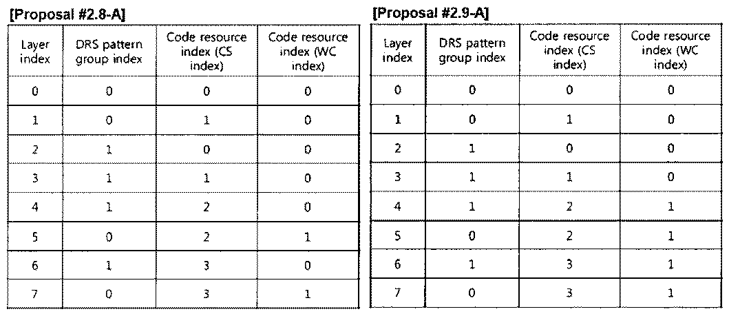


표 42


표 43


Claims (15)
- 무선 통신 시스템에서 송신단이 참조 신호(Reference Signal; RS)를 전송하는 방법에 있어서,레이어(layer) 별로 정의된 RS 자원을 확인하는 단계; 및상기 RS 자원을 이용하여, 상기 레이어를 위한 프리코딩 된 RS를 다중 안테나를 통해 수신단으로 전송하는 단계를 포함하고,상기 RS 자원은 자원블록(resource block) 내에서 상기 프리코딩 된 RS가 맵핑되는 RS 자원 패턴 그룹을 지시하는 제1 인덱스와 상기 프리코딩 된 RS를 상기 RS 자원 패턴 그룹 내에 다중화하기 위한 코드 자원을 지시하는 제2 인덱스를 포함하는 RS 전송 방법.
- 제1항에 있어서,각각의 RS 자원 패턴 그룹은 상기 자원블록의 각 슬롯에 위치한 두 개의 인접한 OFDM(Orthogonal Frequency Division Multiplexing) 심볼에 FDM(Frequency Division Multiplexing) 방식으로 정의되고,각각의 RS 자원 패턴 그룹은 시간적으로 인접한 자원요소 쌍(resource element pair)을 복수 개 포함하는 것을 특징으로 하는 RS 전송 방법.
- 제1항에 있어서,상기 제1 인덱스가 지시하는 자원 패턴은 하기 표와 같은 것을 특징으로 하는 RS 전송 방법:
 여기에서, 상기 자원블록은 12개의 부반송파*14개의 OFDM(Orthogonal Frequency Division Multiplexing) 심볼을 포함하고, l은 OFDM 심볼 인덱스를 나타내는 0 이상의 정수이며, k는 부반송파 인덱스를 나타내는 0 이상의 정수이고. 슬롯은 7개의 OFDM 심볼을 포함하며, G0은 RS 자원 패턴 그룹 #0을 나타내고, G1은 RS 자원 패턴 그룹 #1을 나타낸다.
 - 제1항에 있어서,상기 제2 인덱스는 시간 영역에서 상기 프리코딩된 RS에 커버 시퀀스로 사용되는 코드 자원을 지시하는 것을 특징으로 하는 RS 전송 방법.
- 제1항에 있어서,상기 RS 자원과 레이어 인덱스 또는 이와 연관된 값 사이의 맵핑 관계는 제1 인덱스 퍼스트(first) 방식을 따르는 것을 특징으로 하는 RS 전송 방법.
- 제1항에 있어서,상기 RS 자원과 레이어 인덱스 또는 이와 연관된 값 사이의 맵핑 관계는 랭크 값이 특정 값보다 작은 경우에는 제1 인덱스 퍼스트(first) 방식을 따르고, 상기 랭크 값이 상기 특정 값 이상인 경우에는 제2 인덱스 퍼스트(first) 방식을 따르는 것을 특징으로 하는 RS 전송 방법.
- 제1항에 있어서,상기 RS는 전용 참조 신호(Dedicated Reference Signal; DRS)를 포함하고, DRS 자원과 레이어 인덱스 사이의 맵핑 관계는 하기 표와 같은 것을 특징으로 하는 RS 전송 방법:
 여기에서, 레이어 인덱스는 재정렬(reordering)될 수 있다.
 - 무선 신호를 단말과 송수신하도록 구성된 RF(Radio Frequency) 유닛;상기 단말과 송수신하는 정보 및 기지국의 동작에 필요한 파라미터를 저장하기 위한 메모리; 및상기 RF 유닛과 상기 메모리와 연결되며, 상기 RF 유닛과 상기 메모리를 제어하도록 구성된 프로세서를 포함하되, 상기 프로세서는레이어(layer) 별로 정의된 RS 자원을 확인하는 단계; 및상기 RS 자원을 이용하여, 레이어를 위한 프리코딩 된 RS를 다중 안테나를 통해 수신단으로 전송하는 단계를 포함하고,상기 RS 자원은 상기 RS 자원은 자원블록(resource block) 내에서 상기 프리코딩 된 RS가 맵핑되는 RS 자원 패턴 그룹을 지시하는 제1 인덱스와 상기 프리코딩 된 RS를 상기 RS 자원 패턴 그룹 내에 다중화하기 위한 코드 자원을 지시하는 제2 인덱스를 포함하는 RS 전송 방법을 수행하도록 구성된 기지국.
- 무선 통신 시스템에서 수신단이 참조 신호(Reference Signal; RS)를 처리하는 방법에 있어서,레이어(layer) 별로 정의된 RS 자원을 확인하는 단계;프리코딩 된 RS를 다중 안테나를 통해 송신단으로부터 수신하는 단계; 및상기 RS 자원을 이용하여 상기 프리코딩 된 RS를 검출하는 단계를 포함하고,상기 RS 자원은 자원블록(resource block) 내에서 상기 프리코딩 된 RS가 맵핑되는 RS 자원 패턴 그룹을 지시하는 제1 인덱스와 상기 프리코딩 된 RS를 상기 RS 자원 패턴 그룹 내에 다중화하기 위한 코드 자원을 지시하는 제2 인덱스를 포함하는 RS 처리 방법.
- 제9항에 있어서,상기 제1 인덱스가 지시하는 자원 패턴은 하기 표와 같은 것을 특징으로 하는 RS 처리 방법:
 여기에서, 상기 자원블록은 12개의 부반송파*14개의 OFDM(Orthogonal Frequency Division Multiplexing) 심볼을 포함하고, l은 OFDM 심볼 인덱스를 나타내는 0 이상의 정수이며, k는 부반송파 인덱스를 나타내는 0 이상의 정수이고. 슬롯은 7개의 OFDM 심볼을 포함하며, G0은 RS 자원 패턴 그룹 #0을 나타내고, G1은 RS 자원 패턴 그룹 #1을 나타낸다.
 - 제9항에 있어서,상기 제2 인덱스는 시간 영역에서 상기 프리코딩된 RS에 커버 시퀀스로 사용되는 코드 자원을 지시하는 것을 특징으로 하는 RS 처리 방법.
- 제9항에 있어서,상기 RS 자원과 레이어 인덱스 또는 이와 연관된 값 사이의 맵핑 관계는 제1 인덱스 퍼스트(first) 방식을 따르는 것을 특징으로 하는 RS 처리 방법.
- 제9항에 있어서,상기 RS 자원과 레이어 인덱스 또는 이와 연관된 값 사이의 맵핑 관계는 랭크 값이 특정 값보다 작은 경우에는 제1 인덱스 퍼스트(first) 방식을 따르고, 상기 랭크 값이 상기 특정 값 이상인 경우에는 제2 인덱스 퍼스트(first) 방식을 따르는 것을 특징으로 하는 RS 처리 방법.
- 제9항에 있어서,상기 RS는 전용 참조 신호(Dedicated Reference Signal; DRS)를 포함하고, DRS 자원과 레이어 인덱스 사이의 맵핑 관계는 하기 표와 같은 것을 특징으로 하는 RS 처리 방법:
 여기에서, 레이어 인덱스는 재정렬(reordering)될 수 있다.
 - 무선 신호를 기지국과 송수신하도록 구성된 RF(Radio Frequency) 유닛;상기 기지국과 송수신하는 정보 및 단말의 동작에 필요한 파라미터를 저장하기 위한 메모리; 및상기 RF 유닛과 상기 메모리와 연결되며, 상기 RF 유닛과 상기 메모리를 제어하도록 구성된 프로세서를 포함하되, 상기 프로세서는레이어(layer) 별로 정의된 RS 자원을 확인하는 단계;프리코딩 된 RS를 다중 안테나를 통해 송신단으로부터 수신하는 단계; 및상기 RS 자원을 이용하여 상기 프리코딩 된 RS를 검출하는 단계를 포함하고,상기 RS 자원은 자원블록(resource block) 내에서 상기 프리코딩 된 RS가 맵핑되는 RS 자원 패턴 그룹을 지시하는 제1 인덱스와 상기 프리코딩 된 RS를 상기 RS 자원 패턴 그룹 내에 다중화하기 위한 코드 자원을 지시하는 제2 인덱스를 포함하는 RS 처리 방법을 수행하도록 구성된 단말.
Priority Applications (7)
| Application Number | Priority Date | Filing Date | Title |
|---|---|---|---|
| KR1020117023278A KR101276859B1 (ko) | 2009-04-15 | 2010-04-15 | 참조 신호를 전송하는 방법 및 장치 |
| US13/264,738 US8743807B2 (en) | 2009-04-15 | 2010-04-15 | Method and apparatus for transmitting reference signal |
| CN201080017065.7A CN102396165B (zh) | 2009-04-15 | 2010-04-15 | 发射参考信号的方法和设备 |
| JP2012505824A JP2012524453A (ja) | 2009-04-15 | 2010-04-15 | 参照信号を伝送する方法及び装置 |
| US14/254,602 US9014127B2 (en) | 2009-04-15 | 2014-04-16 | Method and apparatus for transmitting reference signal |
| US14/626,055 US9438326B2 (en) | 2009-04-15 | 2015-02-19 | Method and apparatus for transmitting reference signal |
| US15/222,693 US9838098B2 (en) | 2009-04-15 | 2016-07-28 | Method and apparatus for transmitting reference signal |
Applications Claiming Priority (10)
| Application Number | Priority Date | Filing Date | Title |
|---|---|---|---|
| US16969709P | 2009-04-15 | 2009-04-15 | |
| US61/169,697 | 2009-04-15 | ||
| US17319909P | 2009-04-27 | 2009-04-27 | |
| US61/173,199 | 2009-04-27 | ||
| US17322009P | 2009-04-28 | 2009-04-28 | |
| US61/173,220 | 2009-04-28 | ||
| US22306309P | 2009-07-06 | 2009-07-06 | |
| US61/223,063 | 2009-07-06 | ||
| US23312409P | 2009-08-11 | 2009-08-11 | |
| US61/233,124 | 2009-08-11 |
Related Child Applications (2)
| Application Number | Title | Priority Date | Filing Date |
|---|---|---|---|
| US13/264,738 A-371-Of-International US8743807B2 (en) | 2009-04-15 | 2010-04-15 | Method and apparatus for transmitting reference signal |
| US14/254,602 Continuation US9014127B2 (en) | 2009-04-15 | 2014-04-16 | Method and apparatus for transmitting reference signal |
Publications (3)
| Publication Number | Publication Date |
|---|---|
| WO2010120140A2 WO2010120140A2 (ko) | 2010-10-21 |
| WO2010120140A9 true WO2010120140A9 (ko) | 2011-01-27 |
| WO2010120140A3 WO2010120140A3 (ko) | 2011-03-17 |
Family
ID=42983018
Family Applications (1)
| Application Number | Title | Priority Date | Filing Date |
|---|---|---|---|
| PCT/KR2010/002367 WO2010120140A2 (ko) | 2009-04-15 | 2010-04-15 | 참조 신호를 전송하는 방법 및 장치 |
Country Status (5)
| Country | Link |
|---|---|
| US (4) | US8743807B2 (ko) |
| JP (3) | JP2012524453A (ko) |
| KR (1) | KR101276859B1 (ko) |
| CN (2) | CN102396165B (ko) |
| WO (1) | WO2010120140A2 (ko) |
Families Citing this family (65)
| Publication number | Priority date | Publication date | Assignee | Title |
|---|---|---|---|---|
| JP5322327B2 (ja) | 2009-01-05 | 2013-10-23 | マーベル ワールド トレード リミテッド | Mimo通信システムのコードブックのプリコーディング |
| CN102396165B (zh) | 2009-04-15 | 2014-12-17 | Lg电子株式会社 | 发射参考信号的方法和设备 |
| CN101931485B (zh) | 2009-06-19 | 2014-02-12 | 北京三星通信技术研究有限公司 | 一种专用参考信号生成方法和装置 |
| US9065617B2 (en) * | 2009-08-17 | 2015-06-23 | Qualcomm Incorporated | MIMO related signaling in wireless communication |
| JP6013183B2 (ja) * | 2009-09-07 | 2016-10-25 | エルジー エレクトロニクス インコーポレイティド | 無線通信システムにおいて参照信号を送受信する方法及び装置 |
| US8675794B1 (en) | 2009-10-13 | 2014-03-18 | Marvell International Ltd. | Efficient estimation of feedback for modulation and coding scheme (MCS) selection |
| US8917796B1 (en) * | 2009-10-19 | 2014-12-23 | Marvell International Ltd. | Transmission-mode-aware rate matching in MIMO signal generation |
| CN102056309A (zh) * | 2009-11-02 | 2011-05-11 | 北京三星通信技术研究有限公司 | 一种传输专用参考信号的方法和装置 |
| US8325860B2 (en) | 2009-11-09 | 2012-12-04 | Marvell World Trade Ltd. | Asymmetrical feedback for coordinated transmission systems |
| CN102783120B (zh) | 2009-12-17 | 2015-07-01 | 马维尔国际贸易有限公司 | 用于交叉极化天线的mimo反馈方案 |
| KR101757452B1 (ko) * | 2010-01-08 | 2017-07-13 | 삼성전자주식회사 | 무선 통신 시스템에서 자원 매핑 및 디매핑 방법 및 장치 |
| MX2012008019A (es) * | 2010-01-08 | 2012-11-23 | Fujitsu Ltd | Aparato generador de códigos, aparato generador de señal de referencia y métodos de los mismos. |
| WO2011085509A1 (en) * | 2010-01-12 | 2011-07-21 | Telefonaktiebolaget L M Ericsson (Publ) | Layer-to dm rs port mapping for lte-advanced |
| AU2010342988B2 (en) | 2010-01-20 | 2015-06-11 | Telefonaktiebolaget L M Ericsson (Publ) | Antenna port mapping method and device for demodulation reference signals |
| CA2787774C (en) | 2010-01-22 | 2019-02-12 | Sharp Kabushiki Kaisha | Transmission device, reception device, communication system, and communication method |
| JP5258002B2 (ja) | 2010-02-10 | 2013-08-07 | マーベル ワールド トレード リミテッド | Mimo通信システムにおける装置、移動通信端末、チップセット、およびその方法 |
| KR20110111962A (ko) * | 2010-04-06 | 2011-10-12 | 주식회사 팬택 | 무선통신시스템에서의 전송장치, 수신장치, 정보 전송방법, 정보 수신방법 및 기록매체 |
| CN102143096B (zh) * | 2010-07-16 | 2013-12-04 | 华为技术有限公司 | 发送物理资源块、及信道估计的方法、基站和用户设备 |
| KR20120018266A (ko) | 2010-08-20 | 2012-03-02 | 삼성전자주식회사 | 직교 주파수 분할 다중 접속 방법을 사용하는 무선 통신 시스템에서 기지국의 전력 증폭기 소모 전력 제어 방법 및 장치 |
| US9270359B2 (en) * | 2010-10-05 | 2016-02-23 | Telefonaktiebolaget L M Ericsson (Publ) | Method and arrangement for polarization control in a communication system |
| JP2012100254A (ja) | 2010-10-06 | 2012-05-24 | Marvell World Trade Ltd | Pucchフィードバックのためのコードブックサブサンプリング |
| WO2012093449A1 (ja) | 2011-01-07 | 2012-07-12 | パナソニック株式会社 | 送信装置、受信装置、送信方法、及び受信方法 |
| US9048970B1 (en) | 2011-01-14 | 2015-06-02 | Marvell International Ltd. | Feedback for cooperative multipoint transmission systems |
| CN103548284B (zh) | 2011-03-31 | 2017-07-21 | 马维尔国际贸易有限公司 | 用于协作多点传输的信道反馈 |
| CN104901788B (zh) * | 2011-08-05 | 2018-08-21 | 华为技术有限公司 | 一种导频信号发送方法和设备 |
| WO2013068915A2 (en) | 2011-11-07 | 2013-05-16 | Marvell World Trade Ltd. | Precoding feedback for cross-polarized antennas with magnitude information |
| US8923427B2 (en) | 2011-11-07 | 2014-12-30 | Marvell World Trade Ltd. | Codebook sub-sampling for frequency-selective precoding feedback |
| US9031597B2 (en) | 2011-11-10 | 2015-05-12 | Marvell World Trade Ltd. | Differential CQI encoding for cooperative multipoint feedback |
| US9220087B1 (en) | 2011-12-08 | 2015-12-22 | Marvell International Ltd. | Dynamic point selection with combined PUCCH/PUSCH feedback |
| US8902842B1 (en) | 2012-01-11 | 2014-12-02 | Marvell International Ltd | Control signaling and resource mapping for coordinated transmission |
| JP5934723B2 (ja) | 2012-01-27 | 2016-06-15 | パナソニック インテレクチュアル プロパティ コーポレーション オブ アメリカPanasonic Intellectual Property Corporation of America | 送信装置及び送信方法 |
| WO2013157790A1 (ko) * | 2012-04-20 | 2013-10-24 | 엘지전자 주식회사 | 무선 접속 시스템에서 하향링크 빔 포밍 방법 및 이를 위한 장치 |
| US9143951B2 (en) | 2012-04-27 | 2015-09-22 | Marvell World Trade Ltd. | Method and system for coordinated multipoint (CoMP) communication between base-stations and mobile communication terminals |
| US9397738B2 (en) * | 2012-05-17 | 2016-07-19 | Qualcomm Incorporated | Codebook and feedback design for high order MIMO |
| US9059753B2 (en) * | 2012-09-27 | 2015-06-16 | Nokia Solutions & Networks Oy | Non-codebook based channel state information feedback |
| US20140169409A1 (en) * | 2012-12-14 | 2014-06-19 | Futurewei Technologies, Inc. | Systems and Methods for Open-loop Spatial Multiplexing Schemes for Radio Access Virtualization |
| CN103944662B (zh) * | 2013-01-18 | 2018-10-02 | 中兴通讯股份有限公司 | 一种发射上行解调参考信号的方法和系统 |
| US9871565B2 (en) * | 2013-03-01 | 2018-01-16 | Sony Corporation | MIMO communication method, transmitting device, and receiving device |
| KR20140122530A (ko) * | 2013-04-10 | 2014-10-20 | 주식회사 팬택 | 소형 셀을 지원하는 무선 통신 시스템에서 참조 신호의 구성 장치 및 방법 |
| US9252856B2 (en) | 2013-05-16 | 2016-02-02 | Telefonaktiebolaget L M Ericsson (Publ) | Method and apparatus for rank override |
| KR102155090B1 (ko) * | 2013-08-09 | 2020-09-11 | 팬텍 주식회사 | 무선 통신 시스템에서 참조 신호를 전송하는 방법 및 장치 |
| CN104581835B (zh) * | 2013-10-29 | 2018-09-21 | 华为技术有限公司 | 映射下行参考信号的装置及方法 |
| US20160029225A1 (en) * | 2014-07-22 | 2016-01-28 | Alcatel-Lucent Usa Inc. | Active Antenna System And Method With Full Antenna Ports Dimension |
| US20160028451A1 (en) * | 2014-07-22 | 2016-01-28 | Alcatel-Lucent Usa Inc. | Active Antenna System And Method With Full Antenna Ports Dimension |
| US10680771B2 (en) | 2014-08-28 | 2020-06-09 | Qualcomm Incorporated | Reference signal transmission and averaging for wireless communications |
| JP6027637B2 (ja) * | 2015-01-22 | 2016-11-16 | テレフオンアクチーボラゲット エルエム エリクソン(パブル) | 復調参照信号のためのアンテナポートマッピング方法および装置 |
| CN107408969B (zh) * | 2015-03-12 | 2021-05-07 | 华为技术有限公司 | 一种天线模式选择方法、装置及系统 |
| WO2016201700A1 (zh) * | 2015-06-19 | 2016-12-22 | 海能达通信股份有限公司 | 基于集群业务的同频组网方法和装置 |
| KR102095894B1 (ko) * | 2015-07-14 | 2020-04-01 | 텔레호낙티에볼라게트 엘엠 에릭슨(피유비엘) | 통신 네트워크에서의 기준 신호 |
| CN106534001B (zh) * | 2015-09-10 | 2019-07-05 | 上海朗帛通信技术有限公司 | 一种低延迟的无线通信方法和装置 |
| CN107493246B (zh) * | 2015-11-05 | 2020-07-24 | 索尼公司 | 无线通信系统中的装置和方法 |
| DE102015122564B4 (de) * | 2015-12-22 | 2021-06-10 | Intel IP Corporation | Kommunikationsvorrichtung und verfahren zum verarbeiten eines signals |
| US10326572B2 (en) * | 2016-03-14 | 2019-06-18 | Lg Electronics | Enhanced channel estimation method and user equipment performing the same |
| JP6679764B2 (ja) * | 2016-06-17 | 2020-04-15 | エルジー エレクトロニクス インコーポレイティド | 下りリンク信号受信方法及び使用者器機と、下りリンク信号送信方法及び基地局 |
| CN107733617B (zh) * | 2016-08-12 | 2020-11-06 | 华为技术有限公司 | 参考信号映射方法及装置 |
| CN107888249A (zh) * | 2016-09-30 | 2018-04-06 | 北京信威通信技术股份有限公司 | 一种波束域参考信号发送的方法及装置 |
| US20180159707A1 (en) * | 2016-12-01 | 2018-06-07 | Samsung Electronics Co., Ltd. | Method and apparatus for multistream transmission |
| WO2018137516A1 (en) * | 2017-01-27 | 2018-08-02 | Guangdong Oppo Mobile Telecommunications Corp., Ltd. | Method and apparatus for transmitting signals |
| JP7195153B2 (ja) * | 2017-02-03 | 2022-12-23 | 株式会社Nttドコモ | ユーザ端末及び無線通信方法 |
| KR102366009B1 (ko) * | 2017-05-16 | 2022-02-22 | 삼성전자 주식회사 | 무선 통신 시스템에서 자원 정보 이용 방법 및 장치 |
| CN109327292B (zh) * | 2017-07-31 | 2021-08-03 | 普天信息技术有限公司 | 下行参考信号资源分配方法及装置 |
| CN110072287B (zh) * | 2018-01-24 | 2022-05-10 | 华为技术有限公司 | 基于加扰的数据传输方法 |
| US11381293B2 (en) * | 2019-04-26 | 2022-07-05 | Samsung Electronics Co., Ltd. | Method and apparatus to enable high rank CSI reporting in wireless communication systems |
| CN114144982B (zh) * | 2019-08-01 | 2024-05-10 | 联想(新加坡)私人有限公司 | 用于生成信道状态信息报告的方法和装置 |
| WO2023092016A1 (en) * | 2021-11-19 | 2023-05-25 | Hubbell Incorporated | Electromechanical sensing system |
Family Cites Families (10)
| Publication number | Priority date | Publication date | Assignee | Title |
|---|---|---|---|---|
| EP2020089A4 (en) * | 2006-04-28 | 2011-05-18 | Mitsubishi Electric Res Lab | METHOD AND SYSTEM FOR PROCESSING REFERENCE SIGNALS IN OFDM SYSTEMS USING TRANSMISSION TIME INTERVAL GROUPING |
| US8213943B2 (en) * | 2007-05-02 | 2012-07-03 | Qualcomm Incorporated | Constrained hopping of DL reference signals |
| KR101376233B1 (ko) * | 2007-10-02 | 2014-03-21 | 삼성전자주식회사 | 주파수 분할 다중 접속 방식의 시스템에서 제어 채널의자원 할당 장치 및 방법 |
| EP2293473B8 (en) * | 2008-06-23 | 2016-09-21 | Sun Patent Trust | Method of arranging reference signals and wireless communication base station apparatus |
| CN101340228B (zh) * | 2008-08-07 | 2014-05-28 | 中兴通讯股份有限公司南京分公司 | 一种参考信号的传输方法 |
| CN101340227B (zh) * | 2008-08-15 | 2012-10-10 | 中兴通讯股份有限公司 | 下行参考信号的发送方法和装置 |
| US8340199B2 (en) * | 2008-10-27 | 2012-12-25 | Samsung Electronics Co., Ltd. | 8-transmit antenna reference signal design for downlink communications in a wireless system |
| US20100195748A1 (en) * | 2009-02-02 | 2010-08-05 | Samsung Electronics Co., Ltd. | Method and system for reference signal pattern design in resource blocks |
| WO2010117251A2 (ko) * | 2009-04-10 | 2010-10-14 | 엘지전자 주식회사 | 하향링크 참조신호의 전송방법 및 장치 |
| CN102396165B (zh) * | 2009-04-15 | 2014-12-17 | Lg电子株式会社 | 发射参考信号的方法和设备 |
-
2010
- 2010-04-15 CN CN201080017065.7A patent/CN102396165B/zh active Active
- 2010-04-15 WO PCT/KR2010/002367 patent/WO2010120140A2/ko active Application Filing
- 2010-04-15 CN CN201410697124.XA patent/CN104539327B/zh active Active
- 2010-04-15 KR KR1020117023278A patent/KR101276859B1/ko active IP Right Grant
- 2010-04-15 US US13/264,738 patent/US8743807B2/en active Active
- 2010-04-15 JP JP2012505824A patent/JP2012524453A/ja not_active Ceased
-
2013
- 2013-10-10 JP JP2013212555A patent/JP5607807B2/ja active Active
-
2014
- 2014-04-16 US US14/254,602 patent/US9014127B2/en active Active
- 2014-08-28 JP JP2014173386A patent/JP5849133B2/ja active Active
-
2015
- 2015-02-19 US US14/626,055 patent/US9438326B2/en active Active
-
2016
- 2016-07-28 US US15/222,693 patent/US9838098B2/en active Active
Also Published As
| Publication number | Publication date |
|---|---|
| JP2014064280A (ja) | 2014-04-10 |
| US20150162964A1 (en) | 2015-06-11 |
| US9838098B2 (en) | 2017-12-05 |
| KR20120004438A (ko) | 2012-01-12 |
| US9014127B2 (en) | 2015-04-21 |
| US9438326B2 (en) | 2016-09-06 |
| US20120033630A1 (en) | 2012-02-09 |
| JP5607807B2 (ja) | 2014-10-15 |
| KR101276859B1 (ko) | 2013-06-18 |
| US20140226617A1 (en) | 2014-08-14 |
| CN102396165A (zh) | 2012-03-28 |
| JP2012524453A (ja) | 2012-10-11 |
| CN104539327B (zh) | 2019-11-22 |
| JP5849133B2 (ja) | 2016-01-27 |
| WO2010120140A2 (ko) | 2010-10-21 |
| JP2015029280A (ja) | 2015-02-12 |
| CN102396165B (zh) | 2014-12-17 |
| US20160337019A1 (en) | 2016-11-17 |
| CN104539327A (zh) | 2015-04-22 |
| US8743807B2 (en) | 2014-06-03 |
| WO2010120140A3 (ko) | 2011-03-17 |
Similar Documents
| Publication | Publication Date | Title |
|---|---|---|
| WO2010120140A9 (ko) | 참조 신호를 전송하는 방법 및 장치 | |
| WO2011040797A2 (ko) | 하향링크 참조신호의 전송방법 및 장치 | |
| WO2011008062A2 (ko) | 하향링크 참조신호의 전송방법 및 장치 | |
| WO2011019228A2 (ko) | 다중 안테나를 지원하는 무선 통신 시스템에서 하향링크 참조신호를 전송하는 방법 및 장치 | |
| WO2011034340A2 (ko) | 다중 안테나를 지원하는 무선 통신 시스템에서 하향링크 참조신호를 전송하는 방법 및 장치 | |
| WO2018128399A1 (ko) | 무선 통신 시스템에서, 참조 신호를 전송하는 방법 및 이를 위한 장치 | |
| WO2011046349A2 (ko) | 다중 안테나를 지원하는 무선 통신 시스템에서 하향링크 참조 신호 전송 전력 정보 제공 방법 및 장치 | |
| WO2010090415A2 (en) | Apparatus and method for transmitting signal in wireless communication system | |
| WO2010087644A2 (ko) | 무선 통신 시스템에서 참조신호 전송 장치 및 방법 | |
| WO2016163797A1 (ko) | 전 차원 다중입력 다중출력 무선 통신 시스템에서 채널상태정보 참조신호 송수신 방법 및 장치 | |
| WO2010018983A2 (en) | Method of transmitting data using spatial multiplexing | |
| WO2010151092A2 (ko) | 상향링크 mimo 전송에서 참조신호를 전송하는 방법 및 장치 | |
| WO2011087345A2 (en) | Method and apparatus for allocating channel state information-reference signal in wireless communication system | |
| WO2011053051A2 (en) | Methods and apparatus for multi-user mimo transmissions in wireless communication systems | |
| WO2011084009A2 (en) | Method and apparatus for mapping/demapping resource in wireless communication system | |
| WO2014069821A1 (ko) | 다중 안테나 시스템에서 참조 신호의 전송장치 및 방법 | |
| WO2016010379A1 (ko) | 무선 통신 시스템에서 채널을 추정하는 방법 및 장치 | |
| WO2011046355A2 (en) | Method and system of multi-layer beamforming | |
| WO2010064854A2 (en) | Method for transmitting and receiving downlink reference signals in a wireless communication system having multiple antennas | |
| WO2011122835A2 (en) | Method and apparatus for controlling retransmission on uplink in a wireless communication system supporting mimo | |
| WO2016028111A1 (ko) | 하이브리드 빔포밍을 지원하는 무선접속시스템에서 아날로그 빔을 추정하기 위한 트레이닝 심볼 전송 방법 및 장치 | |
| WO2016099057A1 (ko) | 상향링크 데이터의 복조를 위한 dmrs를 전송하는 방법 및 mtc 기기 | |
| WO2017047971A1 (ko) | 복조 참조 신호 송수신 방법 및 이를 이용한 장치 | |
| WO2013022326A2 (en) | System and method for physical downlink control and hybrid-arq indicator channels in lte-a systems | |
| WO2011046413A2 (ko) | 중계기를 지원하는 무선 통신 시스템에서 다중 사용자 mimo 참조신호를 전송하는 방법 및 장치 |
Legal Events
| Date | Code | Title | Description |
|---|---|---|---|
| WWE | Wipo information: entry into national phase |
Ref document number: 201080017065.7 Country of ref document: CN |
|
| 121 | Ep: the epo has been informed by wipo that ep was designated in this application |
Ref document number: 10764679 Country of ref document: EP Kind code of ref document: A2 |
|
| ENP | Entry into the national phase |
Ref document number: 20117023278 Country of ref document: KR Kind code of ref document: A |
|
| WWE | Wipo information: entry into national phase |
Ref document number: 13264738 Country of ref document: US Ref document number: 2012505824 Country of ref document: JP |
|
| NENP | Non-entry into the national phase |
Ref country code: DE |
|
| 122 | Ep: pct application non-entry in european phase |
Ref document number: 10764679 Country of ref document: EP Kind code of ref document: A2 |