WO2010116632A1 - 光ディスク装置および多層光ディスクにおける層間ジャンプ方法 - Google Patents
光ディスク装置および多層光ディスクにおける層間ジャンプ方法 Download PDFInfo
- Publication number
- WO2010116632A1 WO2010116632A1 PCT/JP2010/002050 JP2010002050W WO2010116632A1 WO 2010116632 A1 WO2010116632 A1 WO 2010116632A1 JP 2010002050 W JP2010002050 W JP 2010002050W WO 2010116632 A1 WO2010116632 A1 WO 2010116632A1
- Authority
- WO
- WIPO (PCT)
- Prior art keywords
- layer
- interlayer jump
- optical disc
- jump
- focus position
- Prior art date
- Legal status (The legal status is an assumption and is not a legal conclusion. Google has not performed a legal analysis and makes no representation as to the accuracy of the status listed.)
- Ceased
Links
Images


Classifications
-
- G—PHYSICS
- G11—INFORMATION STORAGE
- G11B—INFORMATION STORAGE BASED ON RELATIVE MOVEMENT BETWEEN RECORD CARRIER AND TRANSDUCER
- G11B7/00—Recording or reproducing by optical means, e.g. recording using a thermal beam of optical radiation by modifying optical properties or the physical structure, reproducing using an optical beam at lower power by sensing optical properties; Record carriers therefor
- G11B7/08—Disposition or mounting of heads or light sources relatively to record carriers
- G11B7/085—Disposition or mounting of heads or light sources relatively to record carriers with provision for moving the light beam into, or out of, its operative position or across tracks, otherwise than during the transducing operation, e.g. for adjustment or preliminary positioning or track change or selection
- G11B7/08505—Methods for track change, selection or preliminary positioning by moving the head
- G11B7/08511—Methods for track change, selection or preliminary positioning by moving the head with focus pull-in only
-
- G—PHYSICS
- G11—INFORMATION STORAGE
- G11B—INFORMATION STORAGE BASED ON RELATIVE MOVEMENT BETWEEN RECORD CARRIER AND TRANSDUCER
- G11B7/00—Recording or reproducing by optical means, e.g. recording using a thermal beam of optical radiation by modifying optical properties or the physical structure, reproducing using an optical beam at lower power by sensing optical properties; Record carriers therefor
- G11B2007/0003—Recording, reproducing or erasing systems characterised by the structure or type of the carrier
- G11B2007/0009—Recording, reproducing or erasing systems characterised by the structure or type of the carrier for carriers having data stored in three dimensions, e.g. volume storage
- G11B2007/0013—Recording, reproducing or erasing systems characterised by the structure or type of the carrier for carriers having data stored in three dimensions, e.g. volume storage for carriers having multiple discrete layers
-
- G—PHYSICS
- G11—INFORMATION STORAGE
- G11B—INFORMATION STORAGE BASED ON RELATIVE MOVEMENT BETWEEN RECORD CARRIER AND TRANSDUCER
- G11B7/00—Recording or reproducing by optical means, e.g. recording using a thermal beam of optical radiation by modifying optical properties or the physical structure, reproducing using an optical beam at lower power by sensing optical properties; Record carriers therefor
- G11B7/08—Disposition or mounting of heads or light sources relatively to record carriers
- G11B7/09—Disposition or mounting of heads or light sources relatively to record carriers with provision for moving the light beam or focus plane for the purpose of maintaining alignment of the light beam relative to the record carrier during transducing operation, e.g. to compensate for surface irregularities of the latter or for track following
- G11B7/0908—Disposition or mounting of heads or light sources relatively to record carriers with provision for moving the light beam or focus plane for the purpose of maintaining alignment of the light beam relative to the record carrier during transducing operation, e.g. to compensate for surface irregularities of the latter or for track following for focusing only
Definitions
- the present invention relates to a recording / reproducing apparatus for a single-area layer type optical disc.
- the present invention relates to an optical disc apparatus capable of recording and reproducing a 16-layer or 20-layer multi-layer optical disc with a 405 nm blue-violet laser light source having a high NA of 0.85 or more and an interlayer jump method in a multilayer optical disc.
- an optical disc provided with N layers (an integer of 2 or more) of information layers stacked is referred to as an “N layer disc”.
- An optical disc having a plurality of information layers is generically referred to as a “multilayer optical disc”.
- a “single area layer type optical disc” is an optical disc in which light irradiating each information layer is incident from one surface of the optical disc.
- the distance from the disc surface 100a on which light is incident to each information layer may be referred to as the “depth” of the information layer.
- a transparent cover layer called a “light transmission layer” exists between the information layer having the closest depth and the disc surface 100a.
- the distance between the focused information layer and the disc surface 100a, that is, the depth of the information layer is referred to as the “light transmitting layer thickness”.
- the information layer located farthest from the disc surface 100a is referred to as “L1 layer”.
- the N information layers are referred to as an L1 layer, an L2 layer,..., An LN layer in order of approaching the disc surface 100a.
- the information layer closest to the disc surface 100a is the L4 layer.
- Data recorded on the optical disc is reproduced by irradiating a rotating optical disc with a light beam having a relatively weak constant light amount and detecting reflected light modulated by the optical disc.
- a reproduction-only optical disc information by pits is previously recorded in a spiral shape at the manufacturing stage of the optical disc.
- a recording material film capable of optically recording / reproducing data is deposited on the surface of a substrate on which a track having spiral lands or grooves is formed by a method such as vapor deposition. Has been.
- the optical disc When data is recorded on a rewritable optical disc, the optical disc is irradiated with a light beam whose amount of light is modulated in accordance with the data to be recorded, thereby changing the characteristics of the recording material film locally to write the data. Do.
- a multilayer optical disc when data is read from a certain information layer (referred to as “layer A”) of a plurality of stacked information layers, or when data is written to the layer A, the light beam is focused on the layer A.
- layer A a certain information layer
- layer B an information layer other than the layer A
- the light beam is focused on the layer B.
- the movement of the focus position of the light beam from one information layer (current layer) to another information layer (target layer) is referred to as “interlayer movement” or “focus jump”.
- the movement of the focus position of the light beam in the depth direction of the information layer (in the thickness direction of the optical disk) can be performed by a focus actuator in the optical pickup.
- the optical pickup includes a laser light source that emits a light beam, an objective lens that focuses the light beam, and an actuator that moves the position of the objective lens.
- the actuator can be divided into a tracking actuator that moves the objective lens in the radial direction of the optical disc and a focus actuator that moves the objective lens in the thickness direction of the optical disc.
- Patent Document 1 discloses a conventional technique for performing a focus jump in a dual-layer disc of DVD or a dual-layer disc of Blu-ray Disc (BD).
- a method of focus jump in a BD double-layer disc disclosed in Patent Document 1 first, the movement of the spherical aberration correction mechanism is started, and the movement of the objective lens by the focus actuator is started after a predetermined time has elapsed.
- the predetermined time corresponds to approximately 1 ⁇ 2 of the time required to move the spherical aberration correction mechanism from the position corresponding to the first recording layer to the position corresponding to the second recording layer.
- the movement of the objective lens by the focus actuator is started when the spherical aberration correction mechanism is approaching the position corresponding to the second recording layer, when the focus position moves to the second recording layer, the spherical surface is corrected.
- the aberration correction mechanism is also approaching the position corresponding to the second recording layer, and focus servo can be correctly performed on the second recording layer.
- the movement of the focus position is started when the spherical aberration correction mechanism moves to a substantially intermediate position between the position corresponding to the first recording layer and the position corresponding to the second recording layer. Therefore, the focus servo can be correctly executed after the focus position moves to the second recording layer.
- Patent Document 1 when performing a focus jump that moves a focus position over two or more recording layers at a time in a multilayer optical disc of three or more layers, a spherical aberration correction mechanism from the current recording layer to the adjacent recording layer And the focus actuator is moved and the focus position is once brought into focus on the adjacent recording layer.
- the focus jump to the next adjacent recording layer is executed and the focus jump to each adjacent recording layer is repeated a predetermined number of times, the focus servo becomes unstable even when two or more recording layers are moved. There was no movement between layers.
- the conventional interlayer jump technology was developed assuming a two-layer disc. According to such a conventional interlayer jump method, the spherical aberration is adjusted to the cover thickness of the target layer (depth of the target layer) before executing the focus jump. In another conventional technique, spherical aberration correction is adjusted to an intermediate value between the target layer and the current layer, the focus is removed, and movement toward the target layer is started.
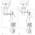
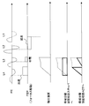
- FIGS. 1 and 2 show the waveforms of the light beam, the FE signal, and the drive signal in the two-layer disc and the four-layer disc when spherical aberration correction is performed so as to minimize the spherical aberration in the target layer at the time of focus jump. .
- FIG. 1A shows a cross-sectional configuration of a two-layer BD.
- a state where the L1 layer is in focus is schematically shown
- a state where the L2 layer is in focus is schematically shown.
- the focus position is moved by moving the objective lens in the thickness direction of the optical disk.
- FIG. 1B shows the waveform of the S-shaped signal and the acceleration pulse P1 and deceleration pulse P2 on the focus drive signal when moving from the L1 layer to the L2 layer.
- FIG. 1C shows an S-shaped waveform and an acceleration pulse P1 and a deceleration pulse P2 on the focus drive signal when moving from the L2 layer to the L1 layer.
- the “S-shaped signal” is a waveform portion that appears in the FE signal in the process in which the focus position approaches the information layer and eventually passes away through the information layer.
- the S-shaped signal has a non-zero amplitude when the focus position of the light beam is located in the vicinity of the information layer.
- One S-shaped signal is usually composed of two peak portions having different polarities that appear in the FE signal. There is a zero cross point between the two peaks. The zero cross point of the S-shaped signal means that the focus position is on the information layer (focused).
- the width of the peak portion of the S-shaped signal may be referred to as a “detection range”.
- the polarities of the acceleration pulse P1 and the deceleration pulse P2 are “positive” when a force is applied in a direction in which the objective lens approaches the optical disk, and are described upward in the figure.
- the polarity of the acceleration pulse P1 and the deceleration pulse P2 becomes “negative” and is shown downward in the figure.
- the upward pulse in the figure contributes to “acceleration” when applied when the objective lens approaches the optical disc, but contributes to “deceleration” when applied when the objective lens moves away from the optical disc.
- the output of the S layer on one side of the target layer that appears when approaching the target layer is detected and the deceleration pulse P2 is output.
- the deceleration pulse P2 is detected at the time when the amplitude (polarity change positive or negative) of one side of the S-shaped signal of the target layer that appears when approaching the target layer is detected. Is outputted, the brake is applied to the movement of the focus position sufficiently before the target layer.
- the interlayer pitch is small as shown in FIG. For this reason, even if the deceleration pulse P2 is output when the S-side output of the target layer that appears when the focus position approaches the target layer is detected, the brake timing is slow, and the focus control in the target layer is pulled in. Sometimes it failed.
- FIG. 3A shows a cross-sectional configuration of the two-layer BD.
- FIG. 3B shows an S-shaped waveform when moving from the L1 layer to the L2 layer, and an acceleration pulse P1 and a deceleration pulse P2 on the focus drive signal.
- FIG. 3C shows an S-shaped waveform when moving from the L2 layer to the L1 layer, and an acceleration pulse P1 and a deceleration pulse P2 on the focus drive signal.
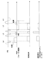
- FIG. 4A shows a cross-sectional configuration of a four-layer BD.
- FIG. 4B shows an S-shaped waveform when moving from the L1 layer to the L4 layer, and an acceleration pulse P1 and a deceleration pulse P2 on the focus drive signal.
- FIG. 4C shows an S-shaped waveform when moving from the L4 layer to the L1 layer, and an acceleration pulse P1 and a deceleration pulse P2 on the focus drive signal.
- an object of the present invention is to provide an optical disc apparatus that realizes stable and high-speed interlayer movement even in a multilayer optical disc having a larger number of layers than a two-layer disc, and an interlayer jump method in the multilayer optical disc.
- An optical disc apparatus includes an interlayer jump control unit for controlling an interlayer jump at a focus position in a multilayer optical disc having a plurality of stacked information layers, and spherical aberration correction corresponding to each of the plurality of information layers in the optical disc.
- a spherical aberration correction unit that can be performed, and an S-shaped signal detection unit that detects an S-shaped signal from an information layer included in the plurality of information layers after starting an interlayer jump of the focus position,
- the aberration correction unit performs spherical aberration correction according to the information layer that starts deceleration of the focus position movement in the interlayer jump before or after the start of the interlayer jump at the focus position, and the interlayer jump control unit Focus position movement in the interlayer jump in response to detection of an S-shaped signal from the information layer subjected to aberration correction It begins to decelerate.
- the information layer that starts decelerating the focus position movement in the interlayer jump is located between the information layer where the focus position existed at the start of the interlayer jump and the target information layer of the interlayer jump.
- Information layer is located between the information layer where the focus position existed at the start of the interlayer jump and the target information layer of the interlayer jump.
- the information layer that starts decelerating focus position movement in the interlayer jump is an information layer adjacent to the target information layer of the interlayer jump.
- the spherical aberration correction unit completes the spherical aberration correction according to the information layer positioned before the start of the interlayer jump and before the target information layer of the interlayer jump.
- the spherical aberration correction unit switches the correction amount of the spherical aberration according to the movement of the focus position after the start of the interlayer jump.
- the spherical aberration correction unit minimizes spherical aberration correction in the information layer closest to the focus position that is moving during the interlayer jump among the plurality of information layers.
- the interlayer jump control unit accelerates focus position movement based on an S-shaped signal detection interval obtained when the focus position crosses each of the plurality of information layers after the start of the interlayer jump. Adjust deceleration.
- the interlayer jump method in the multilayer optical disc of the present invention is an interlayer jump method for controlling the interlayer jump at the focus position in the multilayer optical disc having a plurality of stacked information layers, and before or after the start of the interlayer jump at the focus position, A step of correcting spherical aberration in accordance with the information layer starting deceleration of the focus position movement in the interlayer jump, and detecting an S-shaped signal from the information layer on which the spherical aberration correction has been performed after starting the interlayer jump. And a step of starting to decelerate focus position movement in the interlayer jump in response to detection of the S-shaped signal from the information layer on which the spherical aberration has been performed.
- the information layer for starting the deceleration of the focus position movement in the interlayer jump is selected from a plurality of information layers including an information layer adjacent to the target information layer of the interlayer jump and an information layer located in the vicinity thereof. It is a specific layer.
- the information layer that starts the deceleration of the focus position movement in the interlayer jump is an information layer adjacent to the target information layer of the interlayer jump.
- the method includes a step of performing spherical aberration correction suitable for a target information layer of the interlayer jump after performing the deceleration.
- the method includes a step of determining an interlayer jump pattern by using total layer number information of the multilayer optical disc and interlayer jump information including an interlayer jump source and an interlayer jump destination.
- the interlayer jump pattern includes at least one of a layer that performs spherical aberration correction before the interlayer jump, a layer that generates a deceleration signal, and a maximum number of layers that can jump at one time.
- the interlayer jump pattern includes a pattern that moves from an interlayer jump source to an interlayer jump destination in a plurality of times.
- S-shaped signals obtained from each information layer in the multilayer optical disc do not overlap each other.
- the method of the interlayer jump is changed according to an interlayer jump in a direction in which the objective lens approaches the multilayer optical disc and an interlayer jump in a direction away from the multilayer optical disc.
- the number of information layers that the focus position crosses during the interlayer jump is smaller in the interlayer jump in the direction in which the objective lens approaches the multilayer optical disk than in the interlayer jump in the direction away from the multilayer optical disk.
- Another optical disc apparatus includes an interlayer jump control unit that controls an interlayer jump at a focus position in a multilayer optical disc having a plurality of stacked information layers, and a target information layer for the interlayer jump after the interlayer jump is started.
- An S-shaped signal detecting unit for detecting an S-shaped signal from an information layer adjacent to the front side of the head, and the interlayer jump control unit is configured to move a focus position in the interlayer jump in response to the detection of the S-shaped signal. Deceleration is started, and maximum deceleration is performed on the information layer adjacent to the front side of the target information layer.
- An interlayer jump method in another multilayer optical disc of the present invention is an interlayer jump method for controlling an interlayer jump at a focus position in a multilayer optical disc having a plurality of stacked information layers, and the interlayer jump is started after the interlayer jump is started.
- a step of detecting an S-shaped signal from an information layer adjacent to the front side of the target information layer of the jump, and in response to the detection of the S-shaped signal, decelerating focus position movement in the interlayer jump is started, and the target information Performing maximum deceleration on an information layer adjacent to the front side of the layer.
- the optical disc apparatus and the interlayer jump method of the present invention perform the deceleration control on the information layer on which the spherical aberration is performed after starting the interlayer jump in the multilayer optical disc, it depends on the interlayer distance and the number of layers of the loaded multilayer optical disc.
- the focus position can be decelerated at the optimal timing. For this reason, a stable interlayer jump can be realized even in a multilayer optical disc having a large number of information layers.
- the optical disc apparatus and the interlayer jump method of the present invention move to a desired information layer all at once, so that the adjacent layer is once subjected to focus control and stabilized, and then the movement to the next adjacent layer is repeated. Further, the travel time can be greatly shortened. As a result, not only long-time recording but also 3D recording and random accessibility can be ensured, so that it is possible to provide applications and devices that take advantage of the multi-layered large capacity, such as substitution of a hard disk.
- maximum deceleration is performed in response to detection of an S-shaped signal from the information layer adjacent to the front side of the target information layer of the interlayer jump. This makes it possible to reliably stop the interlayer jump in the target information layer as compared to the case of responding to detection of the S-shaped signal from the target information layer.
- the spherical aberration does not need to be minimized in the information layer adjacent to the front side of the target information layer.
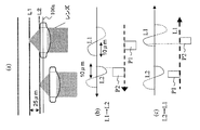
- (A) is a cross-sectional configuration diagram of the two-layer BD
- (b) is an L1 layer in the case where spherical aberration correction is performed so as to minimize spherical aberration in the L2 layer (depth 75 ⁇ m) of the two-layer BD.
- (c) is a case where spherical aberration correction is performed so as to minimize spherical aberration in the L1 layer (depth 100 ⁇ m) of the two-layer BD.
- Waveform diagram of focus error (FE) signal obtained from each of L1, L2 layer (A) is a cross-sectional configuration diagram of a four-layer BD, and (b) is L1-L4 when spherical aberration correction is performed to minimize spherical aberration in the L4 layer (depth 75 ⁇ m) of the four-layer BD.
- (C) is a waveform diagram of a focus error (FE) signal obtained from each of the layers, and (c) shows a case where spherical aberration correction is performed so as to minimize spherical aberration in the L1 layer (depth of 100 ⁇ m) of the four-layer BD.
- Waveform diagram of focus error (FE) signal obtained from each of L1 to L4 layers (A) is a cross-sectional configuration diagram of the two-layer BD
- (b) is a waveform diagram of acceleration and deceleration pulses on an S-shaped waveform and a focus drive signal when moving from the L1 layer to the L2 layer
- (c) Waveform diagram of S-curve waveform and acceleration / deceleration pulse on focus drive signal when moving from L2 layer to L1 layer
- A) is a cross-sectional configuration diagram of a four-layer BD
- (b) is a waveform diagram of an S-shaped waveform and acceleration and deceleration pulses on a focus drive signal when moving from the L1 layer to the L4 layer
- (c) Waveform diagram of S-shaped waveform and acceleration / deceleration pulse on focus drive signal when moving from L4 layer to L1 layer
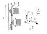
- (A) is a cross-sectional configuration diagram of a two-layer BD
- (b) is an
- FIG. 7 is a detailed block diagram of the optical pickup, the servo control circuit and its peripheral part.
- (A) And (b) is a figure which shows an example of an internal structure of the spherical aberration correction part 128 of FIG.
- FIG. 1 Schematic diagram showing the objective lens when the focus jump operation is performed from the nearest layer (L4 layer) to the farthest layer (L1 layer) and the S-shaped signal when the focus position passes through each layer of the multilayer BD disc.
- Flow chart of focus jump operation Waveform diagram of S-shaped signal and deceleration pulse P2 enlarged around the L7 layer part which is the brake layer The figure which showed the brake layer in each movement pattern of 2 layer BD, 4 layer BD, and 8 layer BD, the maximum number of crossing layers, and the frequency
- Waveform diagram showing the timing of the S-shaped signal, acceleration pulse P1 and deceleration pulse P2 appearing on the FE in the first movement (L1 layer to L5 layer), the second movement (L5 layer to L8 layer)
- (b) is a figure which shows the other example of an internal structure of the spherical aberration correction part 128 of FIG.
- the double-layer disc is an S-shaped signal capable of focus jumping even when the width (detection range) of one side of the S-shaped signal is 10 ⁇ m.
- a multilayer BD having three or more information layers it is necessary to stack the layers with a smaller interlayer pitch than in the two-layer BD. Therefore, in order to detect an independent S-shaped signal of each layer and reduce interlayer crosstalk. It is necessary to narrow the detection range of the S-shaped signal. If the detection range of the S-shaped signal is not narrowed, the S-shaped signals from the adjacent information layers overlap with each other and interlayer crosstalk occurs, making it difficult to identify individual information layers by the S-shaped signal. For example, in a four-layer BD with an interlayer pitch of up to 5 ⁇ m, as shown in FIG.
- the width (detection range) of one side of the S-shaped signal is narrow to 2 ⁇ m so that the S-shaped signal in each layer can be detected. There is a need to. Therefore, as shown in the figure, at the time of interlayer jump, an S-shaped signal is not generated in each layer unless it is just before the target layer.
- an interlayer jump is performed from the L1 layer to the L2 layer.
- 5 (a) and 6 (a) schematically show a cross-sectional configuration of the two-layer BD and a state where the L1 layer and the L2 layer are in focus.
- FIG. 5B shows the waveform of the FE signal obtained from each of the L1 layer and the L2 layer when spherical aberration correction is performed so as to minimize spherical aberration in the L2 layer (depth 75 ⁇ m) of the two-layer BD. Is shown.
- FIG. 6B is obtained from each of the L1 layer and the L2 layer when the spherical aberration correction is performed so as to minimize the spherical aberration in the L1 layer (depth of 100 ⁇ m) of the two-layer BD.
- the waveform of the FE signal is shown.
- the dead zone range becomes large as shown in the figure, and at the time of focus jump, it is in the vicinity of the current layer or the target layer.
- an S-shaped signal is generated.
- the spherical aberration is adjusted to the target layer (L2 layer) to detect the earlier timing, and the S-shaped signal is detected. Is output, and immediately after detecting the output of the S-shaped signal from the zero level of the dead zone, the deceleration pulse P2 is issued and the brake is applied.
- the timing is generated with the S-shaped signal of the current layer (L1 layer), in order to accurately delay the brake timing, the spherical aberration is kept in accordance with the current layer, and the S-shaped signal While detecting the gradient of the waveform, it may be configured to apply a deceleration pulse after the predetermined delay time has elapsed and apply the brake after the gradient value becomes zero.
- the spherical aberration correction is combined with the information layer (brake layer) for generating the timing to apply the brake, and the spherical aberration correction is minimized in the information layer.
- the S-shaped signal obtained from the information layer is increased and stabilized.
- a deceleration pulse is output based on the S-shaped signal obtained from the information layer.
- the maximum deceleration is performed in response to detection of the S-shaped signal from the information layer adjacent to the front side of the target information layer of the interlayer jump. This makes it possible to reliably stop the interlayer jump in the target information layer as compared to the case of responding to detection of the S-shaped signal from the target information layer.
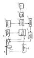
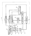
- FIG. 7 is a block diagram of the optical disc apparatus according to the present embodiment.
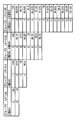
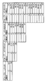
- 8 to 11 are tables showing configuration examples of a single-layer, double-layer to 16-layer multilayer BD disc group supported in the first embodiment.
- the depth of the reference layer (L1 layer) that is located farthest from the disc surface 100a should be 100 ⁇ m. preferable.
- the interlayer distance is preferably 3 ⁇ m or more.
- the interlayer distance may be referred to as an interlayer pitch (LP).
- the thickness of the light transmission layer (the distance between the layer closest to the disk surface 100a and the disk surface 100a) cannot be reduced.
- An optical system used for BD recording / reproduction has a high NA (0.85). As the NA increases, the focal length of the objective lens decreases. Considering these, it is preferable to secure a thickness of the light transmission layer of 25 ⁇ m or more.
- the four patterns (configuration examples) shown in FIGS. 8 to 11 are conceivable for a two-layer, four-layer, six-layer, eight-layer, ten-layer, twelve-layer, fourteen-layer, and sixteen-layer optical disc. .
- the distance between layers is secured as much as possible.
- the layers are equally spaced, and in a 16-layer optical disc, the layers are 5 ⁇ m and the thickness of the light transmission layer is 25 ⁇ m.
- the interlayer distance is alternately changed to cancel the crosstalk.
- the distance between the odd-numbered layer and the even-numbered layer is 5 ⁇ m.
- the distance between the even-numbered layer and the odd-numbered layer is 4 ⁇ m, and the thickness of the light transmission layer is 32 ⁇ m.
- the interlayer 10 and 11 are examples in which the surface and the distance from the surface to the nearest layer (thickness of the light transmission layer) are secured with priority.
- the interlayer is equally spaced.
- the interlayer is 3.125 ⁇ m and the thickness of the light transmission layer is 53.125 ⁇ m.
- the interlayer distance is alternately changed in order to cancel the crosstalk.
- the distance between the odd-numbered layer and the even-numbered layer is 3.125 ⁇ m.
- the distance between the even-numbered layer and the odd-numbered layer is 3 ⁇ m
- the thickness of the light transmission layer is 54 ⁇ m.
- the interlayer distance and the light transmission layer thickness slightly increase or decrease from the above numerical example due to manufacturing variations.
- typical configuration examples of multilayer optical discs are generally summarized in the above four patterns.
- the focus jump in this embodiment can be applied in common to all the above-described patterns. Therefore, the pattern 1 will be described below, and only the necessary portions of the patterns 2, 3, and 4 will be described supplementarily.
- the optical disc apparatus includes a pickup 103, a servo control circuit 106 that controls the operation of the optical pickup 103, a reproduction circuit 110 that reproduces an information signal on the optical disc 100 detected by the optical pickup 103, and information to be recorded on the optical disc 100. And a recording circuit 123 for writing.
- the optical pickup 103 has an optical system that focuses a light beam on the optical disc 100, a photodetector that detects reflected light from the optical disc 100, and a laser diode as a light source.
- the recording circuit 123 writes the information on the optical disc 100 by causing the laser driving circuit 107 to emit a laser diode in a pulsed manner by a predetermined modulation method based on the information to be recorded.
- the optical pickup 103 irradiates the focused laser beam to the optical disc 100 loaded on the optical disc motor 101.
- the RF servo amplifier 104 generates an electrical signal based on the light reflected from the optical disc 100.
- the servo control circuit 106 controls the motor drive circuit 102 and the optical pickup 103 to perform focus and tracking control on the optical disc 100 loaded in the optical disc motor 101. Further, the servo control circuit 106 discriminates whether the optical disc 100 is a BD disc by irradiating the optical disc 100 with a light beam and a lens, and determines whether the optical disc 100 is a BD disc.
- a disc discriminating unit 109 for discriminating a multilayer having an information recording layer is included.
- the reproduction circuit 110 equalizes the electric signal output from the RF servo amplifier 104 with a waveform equivalent circuit or the like to generate an analog reproduction signal.
- the generated reproduction signal is digitized, and data is extracted in synchronization with a read clock (reference clock) by a PLL. Thereafter, the signal is input to the system controller 111 after predetermined demodulation and error correction.
- the system controller 111 is transferred to the host 113 via the I / F circuit 112.
- the recording circuit 123 is added with a header, redundant bits for error correction, etc. and modulated to a predetermined modulation pattern (modulation method), and then the laser driving circuit 107 passes the host 140 through the I / F circuit 131.
- the laser diode in the optical pickup 103 is caused to emit light in pulses.
- Information of “1” or “0” is recorded by changing the reflectance of the recording material (for example, organic material or phase change material) of the optical disc 100 according to the intensity modulation of the laser light incident on the optical disc 100.
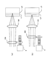
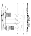
- FIG. 12 is a block diagram showing in more detail the optical pickup, servo control circuit and its peripheral portion of FIG. 7 related to the focus jump of the multilayer optical disc of this embodiment. This will be further described with reference to FIG.
- the illustrated optical pickup 103 includes a light source 122, a coupling lens 124, a polarization beam splitter 126, a spherical aberration correction device 128, an objective lens 130, actuators 131 and 132, a condensing lens 134, and light detection. Part 136.
- the light source 122 is composed of a semiconductor laser diode that emits a light beam.
- a single light source 122 is shown in FIG. 12, but the actual light source is composed of, for example, three semiconductor lasers that emit light beams of different wavelengths.
- one optical pickup includes a plurality of semiconductor lasers that emit light beams of different wavelengths for CD, DVD, and BD, but in FIG. Yes.
- the coupling lens 124 converts the light beam emitted from the light source 122 into parallel light.
- the polarization beam splitter 126 reflects the parallel light from the coupling lens 124. Since the position of the semiconductor laser in the light source 122 and the wavelength of the emitted light beam differ depending on the type of the optical disc, the optimal optical system configuration differs depending on the type of the optical disc 100. For this reason, the actual configuration of the optical pickup 103 is more complicated than that shown in the figure.
- the objective lens 130 focuses the light beam reflected by the polarization beam splitter 126.
- the position of the objective lens 130 is controlled to a predetermined position by the actuator 132 based on the FE signal and the TE signal.
- the focal point of the light beam focused by the objective lens 130 is located on the information recording layer, and the light beam is focused on the information recording layer. A spot is formed.
- one objective lens 130 is shown in FIG. 12, a plurality of objective lenses 130 are actually provided, and different objective lenses 130 are used depending on the type of the optical disc 100.
- the focus servo and tracking servo operate so that the focal point of the light beam follows a desired track in the information recording layer, and the position of the objective lens 130 is controlled with high accuracy.
- the optical disk 100 is an optical disk that performs recording / reproduction with the blue-violet laser diode 122 and the high NA objective lens 130 in particular.
- the optical pickup 103 has a simple configuration as shown in FIG.
- the actual optical pickup 103 may include a light source and an objective lens for CD and / or DVD.
- a focus jump is performed in order to perform data recording / reproduction operations on any layer included in a plurality of information layers of the optical disc 100.
- the objective lens 130 is moved between the layers along the optical axis direction by the action of the actuator 132.
- the spherical aberration correction element 128 includes, for example, an aberration correction lens 228 (FIG. 13) whose position can be changed in the optical axis direction. By adjusting the position of the aberration correction lens 228, the spherical aberration state (correction) is corrected. (A beam expander system) that can change the amount).
- the configuration of the spherical aberration correction unit 128 does not need to have such a beam expander configuration, and may have a configuration in which aberration is corrected by a liquid crystal element, a hinge, or the like.
- the light beam reflected by the information recording layer of the optical disc 100 passes through the objective lens 130, the spherical aberration correction unit 128, and the polarization beam splitter 126 and enters the condenser lens 134.
- the condenser lens 134 focuses the reflected light from the optical disc 100 that has passed through the objective lens 130 and the polarization beam splitter 126 onto the light detection unit 136.
- the light detection unit 136 receives the light that has passed through the condenser lens 134 and converts the optical signal into various electric signals (current signals).
- the light detection unit 136 has, for example, a four-part light receiving region.
- the servo control circuit 106 further includes an FE signal generation unit 150, a TE signal generation unit 151, an S-shaped signal detection unit 160, and a disc determination unit 109.
- the focus control unit 140 can drive the focusing actuator 132 in accordance with an instruction from the CPU 146 to move the objective lens 130 to an arbitrary position along the optical axis direction.
- the tracking control unit 141 can drive the tracking actuator 131 to move the objective lens 130 to an arbitrary position along the radial direction of the optical disc 100, and the optical signal is output from the TE signal output from the TE signal generation unit 151. Tracking control is performed so that the light spot on 100 scans the track.
- the spherical aberration control unit 142 controls the spherical aberration correction unit 128 to a predetermined setting state according to an instruction from the CPU 146.
- FIG. 13 is an internal configuration diagram of the spherical aberration correction unit 128. Specifically, the stepping motor 8 shown in FIG. 13 operates based on a control signal from the spherical aberration control unit 142. For example, in the case of a two-layer disc, the aberration correction lens 228 is attached to the first layer and the second layer. It is moved to a predetermined position corresponding to the cover layer thickness. By changing the position (position in the optical axis direction) of the aberration correction lens 228, the spherical aberration state of the light beam can be adjusted. This has the same operation and function from the 4th layer to the 16th layer and the 20th layer.
- the FE signal generation unit 150 generates an FE signal based on electrical signals output from a plurality of light receiving areas included in the light detection unit 136.
- the generation method of the FE signal is not particularly limited, and an astigmatism method may be used, or a knife edge method may be used. Further, an SSD (spot sized detection) method may be used.
- the FE signal output from the FE signal generation unit 150 is input to the S-shaped signal detection unit 160 in which a predetermined detection threshold is set by a command from the CPU 146.
- the TE signal generation unit 151 generates a TE signal based on electrical signals output from a plurality of light receiving areas included in the light detection unit 136.
- the TE signal generation method is generally a push-pull detection method for recording media having a concavo-convex track such as a recording medium represented by BD-R or BD-RE, and a read-only medium represented by BD-ROM.
- the phase difference detection method is mainly used for the embossed information pre-pits, but the tracking method is not particularly limited.
- the S-shaped signal detection unit 160 detects the S-shaped signal based on whether or not the FE signal exceeds a predetermined threshold while the objective lens 130 is moving in the optical axis direction by focus search.
- Set the aberration value is selected as the brake layer.
- the information layer adjacent to the target information layer between the information layer (jump start layer) for starting the interlayer jump and the target information layer is referred to as an information layer “before” the target information layer.
- the brake layer is typically an information layer positioned in front of the target information layer, but the present invention is not limited to this example. In consideration of the speed of the focus position and the weight of the objective lens during the interlayer movement, it is possible to select an information layer that is more than one layer away from the target information layer as a brake layer.
- tracking control and focus control are turned off, and an acceleration pulse P1 is applied to the actuator 132.
- the deceleration pulse P2 is output when the brake layer is detected. Since the deceleration pulse P2 is applied to the actuator 132 in a layer (brake layer) positioned in front of the target layer, the moving speed of the focus position can be reduced.
- the focus control is turned on when the S-shaped signal detected during the focus jump is counted and the target layer is reached. For this reason, the focus position can be accurately moved to the target layer.
- FIG. 14 shows a four-layer disc as an example.
- FIG. 15 shows a flowchart of the focus jump operation at that time.
- the focus position that moves with the movement of the objective lens is sometimes referred to as a “light spot position”. This is because the cross section of the light beam converged by the objective lens forms the smallest light spot at the focus position.
- the focus position is on the information layer, and a light spot is formed on the information layer.
- a focus jump or an interlayer jump is a movement of a focus position from one information layer to another information layer, and is realized by moving the objective lens in the thickness direction of the optical disc.
- step ST1 shown in FIG. 15 when the focus position is initially focused on the nearest layer (L4 layer) and is in a standby state, a seek command is received from the host 113.
- the target address is the track address of the farthest layer (L1 layer)
- the layer (brake layer) that issues the brake from the condition of the movement from the L4 layer to the L1 layer is the layer jump destination layer (L1 layer).
- the L2 layer in front is used. That is, the timing for issuing the deceleration pulse P2 is determined as an S-shaped signal detected from the front of the L2 layer.
- step ST2 the spherical aberration control unit 142 is commanded, and the aberration correction lens 228 of FIG. 13 is driven so that the correction value matches the cover layer thickness of the L2 layer (depth of the L2 layer).
- spherical aberration correction is performed so that the spherical aberration is minimized in the L2 layer serving as the brake layer. For this reason, when the focus position is on or near the L2 layer, the amplitudes of various signals (RF signal, FE signal, TE signal) obtained from the L2 layer are maximized. As a result, the amplitude of the S-shaped signal is also maximized and sharpened.
- FIG. 14 schematically shows an FE signal (S-shaped signal) obtained from the L1 to L4 layers.
- S-shaped signal FE signal
- the focus position is moved in a state where the spherical aberration is performed so that the spherical aberration is minimized in the L2 layer (ideally zero)
- the S-shape obtained in the L2 layer is obtained.
- the amplitude of the signal is the largest.
- the amplitude of the S-shaped signal obtained from these layers becomes small.
- the waveform of such an S-shaped signal spreads (dulls) in the lateral direction due to spherical aberration, and the detection width increases. According to the dull S-shaped waveform obtained from the layer whose spherical aberration is not corrected, it is difficult to detect the position of the information layer with high accuracy.
- step ST3 After completing the driving of the spherical aberration correction lens, in step ST3, first the S-shaped detection level is lowered (closed to 0). Accordingly, the S-shaped signal M1 (also referred to as the S-shaped signal coarse detection mode M1) that can reliably detect even the S-shaped signal from the information layer that does not match the spherical aberration correction and count the number of the information layer is set. To do. Thereafter, the tracking is turned off, and the acceleration pulse P1 is applied to the focus actuator 132 (step ST4). The focus actuator 132 to which the acceleration pulse P1 is applied accelerates the objective lens 130 in the optical axis direction. Thus, the focus position moves in the direction across the information layer toward the interlayer jump destination.
- the S-shaped detection level is lowered (closed to 0). Accordingly, the S-shaped signal M1 (also referred to as the S-shaped signal coarse detection mode M1) that can reliably detect even the S-shaped signal from the information layer that does not match the spherical
- step ST5 an S-shaped signal is output every time it passes through the L3 layer and the L2 layer, so that the current focus position while moving can be grasped by the count.
- step ST6 since the deceleration pulse P2 is output when passing through the L3 layer that is one layer before the brake layer (L2 layer) based on the count value of the S-shaped signal, the S-shaped signal in the L2 layer is output. Signal detection is performed in the S-shaped signal detail detection mode M2.
- step ST7 the S-shaped signal level is determined.
- the front side of the L2 layer which is the brake output timing
- the peak value of the deceleration pulse P2 corresponding to the required time up to that time is determined and output.
- the timing to end the brake output is when the S-shaped signal is further counted and the layer jump destination layer is reached.
- step ST9 when it is determined that the layer jump destination layer has been reached, in step ST10, the brake output is completed when the S-shaped signal on the near side of the L1 layer is specifically detected. Then, the focus control is immediately turned on. Since the movement of the focus position is sufficiently decelerated, the focus pull-in in the target layer can be realized extremely stably.
- FIG. 14 shows the output of the S-shaped signal for the movement of the layer at this time and the mode switching operation corresponding to it.
- spherical aberration correction is performed before the start of focus jump so that the spherical aberration becomes zero in the brake layer.
- the amplitude of the S-shaped signal in the brake layer is maximized and the S / N ratio is also increased, so that a high-resolution S-shaped signal can be obtained. Therefore, it becomes possible to detect the amplitude level of the S-shaped signal in more detail and to set the start of the fine brake, so that the jump speed control over multiple layers can be realized stably.
- FIG. 16 is a diagram for explaining the operations of the S-shaped signal count mode M1 (S-shaped signal coarse detection mode M1) and the S-shaped signal detailed detection mode M2 of FIG.
- the S-shaped signal count mode M1 is set from the L5 layer to the L6 layer
- the S-shaped signal detailed detection mode M2 is set from the L7 layer to the L8 layer. As shown in the vicinity of the S-shaped signal of the L7 layer in FIG.
- the near side of the L7 layer (direction in which the objective lens approaches the disk surface 100a) L7N, or the vicinity of the center of the L7 layer L7Z, or
- the timing can be freely set (arbitrarily) at the L7 layer fair side (direction in which the objective lens moves away from the disk surface 100a) L7F, and the change of the S-shaped signal can be detected in detail.
- the detection level of the S-shaped waveform is M1 level close to 0 level. Since the spherical aberration correction is shifted in the L5 and L6 layers (there is a relatively large spherical aberration), it is difficult to reliably obtain a sufficiently large S-shaped amplitude level. However, since an S-shaped signal is output even at a low amplitude level, the detection level is lowered so that the S-shaped signal can be reliably counted.
- the S-shaped detection mode M1 when the S-shaped signals of the L5 layer and the L6 layer are counted and the focus position moves to a position close to the L7 layer, the S-shaped detection mode is switched to the detailed detection mode M2.
- the S-shaped detection detailed mode M2 since spherical aberration correction is matched with the L7 layer corresponding to this S-shape, the spherical aberration in the L7 layer is minimized. For this reason, it is easy to obtain the amplitude of a large S-shaped signal.
- the detection level of the S-shaped signal can be set to a fine level. Therefore, it is possible to finely adjust the start point and end point of the deceleration pulse P2, which is particularly important for timing.
- one S-shaped output range is divided into three regions L7N, L7Z, and L7N, and specifically, a timing signal can be generated in each of the divided range regions.
- An appropriate level value is set for the detection level of the S-shaped signal, and a timing signal is generated.
- What is necessary is just to comprise so that acceleration and deceleration may be started at the timing.
- the deceleration pulse P2 can be applied to the focus actuator at the optimum timing.
- the start timing and output value (crest value) of the deceleration pulse P2 it is preferable to appropriately adjust the start timing and output value (crest value) of the deceleration pulse P2 depending on the weight of the lens, the thrust of the actuator, the speed of the lens, etc., but it is used in a conventional BD or DVD.
- the start timing of the deceleration pulse is a short distance of 100 ⁇ m or less, the vicinity of the intermediate position of the moving distance is good, and when moving a long distance of 100 ⁇ m or more, the position near 50 ⁇ m before the target layer is used. It is preferable to start braking. For example, in the case of supporting the focus jump of the multilayer optical disk group (multilayer optical disk group) as shown in FIG.
- the interlayer distance (LP) of each group 0 to 3 is unique. I understand. For this reason, it is possible to obtain information on the distance traveled and the number of layers crossed by the seek pattern. With this combination, the table or calculation formula can be used in the program to quote the brake layer and the focus position at one time. Determine the maximum number of information layers traversed by.
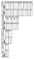
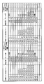
- FIGS. 17 and 18 The table of the brake layer and the maximum number of moving layers and the number of moving layers per time for this determination are shown in FIGS. 17 and 18 by taking 2 layers BD, 4 layers BD, 8 layers BD and 16 layers BD as an example. Shown in
- L2N for example, L2N, L2Z, L2F, etc.
- the brake layer is L2N
- the near side of the L2 layer (the direction in which the objective lens approaches the disk surface 100a)
- the case of L2Z Indicates the vicinity of the center of the L2 layer
- the case of L2F the L2 layer fair side (the direction in which the objective lens moves away from the disk surface 100a).
- the brake layer is indicated as L2N (intermediate), and in this case, the deceleration pulse P2 is the S1 of the L1 layer.
- the deceleration pulse P2 is output.
- the brake layer is indicated as L2Z.
- the L2 layer is set as the brake layer, and the amplitude before or behind the S-shaped signal of the L2 layer is 0 level.
- the level drops to a nearby level (L2Z)
- the deceleration pulse P2 is output.
- the brake layer is indicated as L3N.
- the L3 layer is set as the brake layer, and the S-shaped signal on the front side of the L3 layer is changed from the 0 level (L3Z).
- a deceleration pulse P2 is output upon detection of a rise to a predetermined level in the vicinity.
- the layers L1 to L2, L1 to L3, and L1 to L4 are the same as the 4-layer BD.
- the brake layer is indicated as L3Z.
- the L3 layer is set as the brake layer, and the amplitude before or behind the S-shaped signal of the L3 layer is 0 level.
- a deceleration pulse P2 is output by detecting when the level has dropped to a nearby level (L3Z).
- the movement pattern is indicated as L1 ⁇ L5 ⁇ L8.
- the first jump from the L1 layer to the L5 layer and the L5 layer to the L8 layer are performed first.
- the first brake layer is indicated as L3Z.
- the L3 layer is determined as the brake layer, and the amplitude before or behind the S-shaped signal of the L3 layer is determined. Is detected when it falls to a level near the 0 level (L3Z), a deceleration pulse P2 is output, and when reaching the L5 layer, the focus is once pulled.
- the second brake layer is indicated as L7Z.
- the L7 layer is determined as the brake layer, and before the S-shaped signal of the L7 layer or When the back side amplitude drops to a level near the 0 level (L7Z), a deceleration pulse P2 is output, and when reaching the L8 layer, the focus is drawn to complete the movement.
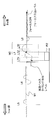
- FIG. 19 shows the cross section of the recording layer of each disc of the first movement (L1 layer to L5 layer) and the second movement (L5 layer to L8 layer), the S-shaped signal appearing on the FE, and the acceleration pulse P1. And a waveform showing the timing of the deceleration pulse P2 output by detecting the S-shaped signal of the brake layer.
- an acceleration pulse P1 is applied to start moving the objective lens toward the L5 layer. Since the spherical aberration is adjusted in the L3 layer, the amplitude of the S-shaped signal is the largest in the L3 layer and decreases as the distance from the L3 layer increases. However, the amplitude of the S-shaped signal does not become 0 even in the information layer other than the L3 layer in the S-shaped count mode M1 (S-shaped signal coarse detection mode M1), so the S-shaped signal of the L1 layer and the L2 layer is detected. It is possible to do. Therefore, it can be detected that the focus position has passed the L1 layer and has reached the L2 layer.
- the passage of the focus position through the L2 layer can be detected by providing an S-shaped signal coarse detection level M1 near the 0 level.
- the S-shaped signal coarse detection mode M1 is switched to the S-shaped signal detailed detection mode M2.
- This mode is a mode in which the amplitude level of the S-shaped signal is set finely.
- the S-shaped signal detail detection mode M2 is also executed after the focus position passes through the L6 layer, as will be described later.
- FIG. 16 is a diagram for explaining the operation of the S-shaped signal detail detection mode M2.
- the near side of the L7 layer (direction in which the objective lens approaches the disk surface 100a) L7N, or the vicinity of the center of the L7 layer L7Z, or The change in the S-shaped signal can be detected in detail on the far side of the L7 layer (the direction in which the objective lens moves away from the disk surface 100a) L7F. Accordingly, the starting point of the deceleration pulse P2 can be finely adjusted. As a result, even if there is a surface blur or variation between layers, the deceleration pulse P2 can be applied to the focus actuator at an optimal timing.
- the focus is turned on.
- the brake layer and the target layer are adjacent layers and the amount of spherical aberration is close, so the amplitude of the S-shaped signal is approximately the same. Therefore, the S-shaped signal detail detection mode M2 is continued from the brake layer to the target layer.
- spherical aberration after applying the deceleration pulse P2 layer in the L3 layer and the L7 layer in order to improve the pull-in by increasing the amplitude of the FE in the target layer L5 layer and the L8 layer reached in the first and second times as much as possible.
- the driving may be started so as to match the target layer with the L5 layer and the L8 layer.
- the maximum number of layers that can be jumped at one time is determined in advance. For example, if the number of layers is determined to be 5, the sequence may be switched to the target layer 3 times for 16-layer access and 4 times for 20-layer access.
- FIG. 18 also shows a part of a 16-layer BD.
- the set value varies depending on the distance between the layers and the number of moving layers.
- the brake layer that generates the deceleration pulse P2 in the same manner the maximum number of moving layers It is possible to determine the number of jumps.
- the multilayer optical disc is divided into a plurality of multilayer groups (0 to 3) according to FIGS. 17 and 18, and the movement pattern of the interlayer jump includes the total layer number information of the multilayer optical disc, the interlayer jump source, and the interlayer jump. It was shown that it was determined using the interlayer jump information including the jump destination. In addition, it is shown that this movement pattern includes a layer that performs spherical aberration correction before an interlayer jump, a brake layer that generates a deceleration signal, and the maximum number of transverse layers that can jump at one time, but at least one of the items May be included. Further, it has been shown that this movement pattern includes a pattern that moves from an interlayer jump source to an interlayer jump destination in a plurality of times. Here, it is desirable that the S-shaped signals obtained from each layer in the multilayer optical disc do not overlap each other.
- the detection range of the S-shaped signal is 2 ⁇ m or less.
- the interlayer distance becomes shorter. Therefore, in order to prevent reliable detection of each layer and interlayer crosstalk, it is necessary to further narrow the detection range of the S-shaped signal. Therefore, the width of the S-shaped signal (the time between the maximum value and the minimum value) detected while the focus position is moved by the focus jump is very narrow. Even in a multilayer optical disk that will be manufactured in the future, an interlayer distance of about 15 ⁇ m to 5 ⁇ m is secured, so that the interval between the S-shaped signal and the S-shaped signal becomes clearer when the detection range of the S-shaped signal is narrowed. For this reason, it becomes easy to detect the information layer based on the S-shaped signal.
- the multilayer optical disc it is possible to detect the timing at which the focus position passes through the information layer during the focus jump with high accuracy based on the S-shaped signal. If the S-shaped signal detected during the focus jump is counted and the detection interval is measured, the moving speed of the focus position (the moving speed in the disc thickness direction) can be obtained.
- the time interval T23 of the minimum value B2 of the S-shaped signal of the layer can be measured. If the time intervals T12 and T23 are longer than a predetermined value (a standard value calculated from the design value of the moving speed), it is determined that the moving speed of the focus position is low, and the deceleration is preferably set small. In this case, the peak value Vbr of the deceleration pulse P2 may be decreased or the deceleration pulse width Tbr may be decreased.
- the time intervals T12 and T23 are shorter than the predetermined value, it is determined that the moving speed of the focus position is high, and it is preferable to increase the deceleration.
- the peak value Vbr of the deceleration pulse P2 may be increased or the deceleration pulse width Tbr may be increased.
- the time interval between the S-shaped signals of the first two layers is measured, but the present invention is not limited to such an example.
- a multilayer optical disk such as a 10-layer disk or a 16-layer disk may jump 10 layers at a time without stopping midway.
- This makes it easy to adjust the moving speed within a predetermined range even in a focus jump having a long moving distance that passes through many layers such as 10 layers and 16 layers.
- the interlayer movement of the focus position can be achieved stably, and the focus can be stably pulled in with the reached target layer.
- one focus jump starts to move by one acceleration pulse P1 and stops moving by one deceleration pulse.
- the focus jump in the present invention is not limited to such an example.
- at least one acceleration pulse for speed adjustment is set between the acceleration pulse P1 and the deceleration pulse P2.
- a deceleration pulse may be applied.
- the focus jump is performed once to the layer immediately before the target layer, and finally the focus jump of only one layer is performed.
- the focus jump downward since the focus jump downward (from the back to the front) has a low risk of collision, it may be moved directly to the target layer.
- the method of interlayer jump may be changed according to the interlayer jump in the direction in which the objective lens approaches the multilayer optical disc and the interlayer jump in the direction in which the objective lens moves away from the multilayer optical disc.
- the number of information layers that the focus position traverses at the time of interlayer jump may be reduced in the interlayer jump in the direction in which the objective lens approaches the multilayer optical disc, compared to the interlayer jump in the direction away from the multilayer optical disc.
- the spherical aberration correction is completed before the start of the focus jump so that the spherical aberration becomes zero in the brake layer.
- the amplitude of the S-shaped signal in the brake layer is maximized and the S / N ratio is also increased, so that a high-resolution S-shaped signal can be obtained.
- more detailed detection of the amplitude level of the S-shaped signal is possible, so that the timing of the deceleration pulse P2 can be accurately determined.
- a drive signal (acceleration pulse, intermediate pulse, deceleration) as shown in FIG. 21 is output to the actuator 132 from the focus actuator drive circuit included in the focus control unit 140 shown in FIG. (Pulse).
- the calculated signal is applied to the spherical aberration corrector 128 (FIG. 12).
- the spherical aberration correction unit 128 shown in FIG. 13 moves the spherical aberration correction lens 228 by the stepping motor 8, but an actuator for correcting spherical aberration is provided between the spherical aberration correction lens 228 and the stepping motor 8. Is preferred.
- FIG. 20 is a diagram illustrating another configuration example of the spherical aberration correction unit 128 including such an actuator 229.
- a drive signal is output from the focus actuator drive circuit provided in the focus control unit 140 to the spherical aberration correction unit 230.
- the spherical aberration correction unit 230 performs an operation on the output drive signal.
- the calculated signal is applied to the stepping motor 8 and the actuator 229, respectively.
- the actuator 229 has a narrow operating range, but has high responsiveness.
- the position of the spherical aberration correction lens 228 is changed by the actuator 229 having a high response speed. It is preferable that fine adjustment can be performed at high speed.
- the first S-shaped signal is an acceleration pulse
- the second S-shaped signal is an intermediate pulse
- the third S-shaped signal is It is configured to issue a deceleration pulse.
- a value (signal) corresponding to the amount of movement in the focus direction can be obtained by extracting the positive pulse toward the target layer and performing integration calculation.
- the obtained signal is subjected to band separation and applied to the stepping motor 8 and the actuator 229 which are elements for correcting spherical aberration.
- the time interval between the S-shaped signal and the S-shaped signal described above may be measured, and the layer where the light beam reaches, that is, the position of the spherical aberration may be estimated from the moving speed of the focus position obtained thereby. .
- FIG. 22 shows an operation in which the CPU 146 measures the time interval between the S-shape and the S-shape during the focus jump, calculates the speed from the time, and feeds back a signal corresponding to the speed to the actuator in the spherical aberration correction unit 128.
- the moving speed of the focus position can be estimated. Therefore, the reach distance of the focus position of the light beam during the focus jump can be easily calculated. In this way, it is possible to know which information layer the focus position is approaching or on which information layer. For this reason, it is possible to sequentially adjust spherical aberration correction to the information layer close to the moving focus position.
- the detection interval of the S-shaped signal is proportional to the moving speed of the focus position
- the timing at which the focus position crosses the information layer and the timing at which the spherical aberration is corrected so as to match the information layer at which the focus position crosses. Can be synchronized.
- the acceleration pulse P1 and the deceleration pulse are each output only once, but the present invention is not limited to such a case as shown in FIG.
- the spherical aberration correction is minimized in the brake layer.
- the brake layer becomes the target information layer. If they are adjacent to each other, the S-shaped signal from the brake layer can be detected with high accuracy.
- an optical disc apparatus may have the following configuration. That is, an interlayer jump control unit that controls an interlayer jump at a focus position in a multilayer optical disc having a plurality of stacked information layers, and an information layer adjacent to the front side of the target information layer of the interlayer jump after starting the interlayer jump And an S-shaped signal detector for detecting the S-shaped signal. Then, the interlayer jump control unit starts the deceleration of the focus position movement in the interlayer jump in response to the detection of the S-shaped signal, and performs the maximum deceleration in the information layer adjacent to the front side of the target information layer.
- an interlayer jump method for controlling an interlayer jump at a focus position in a multilayer optical disc having a plurality of information layers stacked it is possible to execute an interlayer jump method for controlling an interlayer jump at a focus position in a multilayer optical disc having a plurality of information layers stacked. That is, after starting the interlayer jump, a step of detecting an S-shaped signal from the information layer adjacent to the front side of the target information layer of the interlayer jump, and the movement of the focus position in the interlayer jump in response to the detection of the S-shaped signal The step of starting deceleration and performing the maximum deceleration in the information layer adjacent to the front side of the target information layer can be executed.
- optical disc apparatus or the interlayer jump method described above it is possible to reliably stop the interlayer jump in the target information layer as compared with the case of responding to the detection of the S-shaped signal from the target information layer.
- the optical disc apparatus according to the present invention and the interlayer jump method in the multilayer optical disc according to the present invention can realize stable and high-speed interlayer movement, and therefore can be suitably applied to a multilayer optical disc having three or more information layers. Is done.
- the present invention is not limited to the BD as long as it is an optical disk on which a large number of information layers are laminated, and can also be applied to other optical disks (for example, CH-DVD).
- the optical disc apparatus of the present invention can be suitably applied not only to a player having no recording function but also to a recorder and a PC drive having a data recording function.
Landscapes
- Moving Of The Head For Recording And Reproducing By Optical Means (AREA)
- Optical Head (AREA)
- Optical Recording Or Reproduction (AREA)
Abstract
Description
以下、本発明による光ディスク装置および層間ジャンプ方法の実施形態を説明する。
103 光ピックアップ
106 サーボ制御回路
146 層間ジャンプ制御部(CPU)
160 S字信号検出部
Claims (19)
- 積層された複数の情報層を有する多層光ディスクにおけるフォーカス位置の層間ジャンプを制御する層間ジャンプ制御部と、
前記光ディスクにおける前記複数の情報層の各々に応じた球面収差補正を行うことができる球面収差補正部と、
前記フォーカス位置の層間ジャンプを開始した後、前記複数の情報層に含まれる情報層からのS字信号を検出するS字信号検出部と
を備え、
前記球面収差補正部は、前記フォーカス位置の層間ジャンプの開始前または開始後に、前記層間ジャンプにおけるフォーカス位置移動の減速を開始する情報層に応じた球面収差補正を行い、
前記層間ジャンプ制御部は、前記球面収差補正が行われた情報層からのS字信号の検出に応答して前記層間ジャンプにおけるフォーカス位置移動の減速を開始する、光ディスク装置。 - 前記層間ジャンプにおけるフォーカス位置移動の減速を開始する前記情報層は、前記層間ジャンプの開始時に前記フォーカス位置が存在した情報層と前記層間ジャンプの目的情報層との間に位置する情報層である、請求項1に記載の光ディスク装置。
- 前記層間ジャンプにおけるフォーカス位置移動の減速を開始する前記情報層は、前記層間ジャンプの目的情報層に隣接する情報層である、請求項2に記載の光ディスク装置。
- 前記球面収差補正部は、前記層間ジャンプの開始前、前記層間ジャンプの目的情報層の手前に位置する情報層に応じた球面収差補正を完了する、請求項1に記載の光ディスク装置。
- 前記球面収差補正部は、前記層間ジャンプの開始後、前記フォーカス位置の移動に応じて前記球面収差の補正量を切り替える、請求項1に記載の光ディスク装置。
- 前記球面収差補正部は、前記複数の情報層のうち、前記層間ジャンプ中に移動しているフォーカス位置に最も近い情報層で球面収差補正を最小化する、請求項5に記載の光ディスク装置。
- 前記層間ジャンプ制御部は、前記層間ジャンプの開始後、前記フォーカス位置が前記複数の情報層の各々を横切る時に得られるS字信号の検出間隔に基づいてフォーカス位置移動の加速および減速を調整する、請求項1に記載の光ディスク装置。
- 積層された複数の情報層を有する多層光ディスクにおけるフォーカス位置の層間ジャンプを制御する層間ジャンプ方法であって、
フォーカス位置の層間ジャンプの開始前または開始後に、前記層間ジャンプにおけるフォーカス位置移動の減速を開始する情報層に応じた球面収差補正を行うステップと、
前記層間ジャンプを開始した後、前記球面収差補正が行われた情報層からS字信号を検出するステップと、
前記球面収差が行われた情報層からの前記S字信号の検出に応答して前記層間ジャンプにおけるフォーカス位置移動の減速を開始するステップと
を含む、多層光ディスクにおける層間ジャンプ方法。 - 前記層間ジャンプにおけるフォーカス位置移動の減速を開始する情報層は、前記層間ジャンプの目的情報層に隣接する情報層およびその近傍に位置する情報層を含む複数の情報層から選択された特定層である、請求項8に記載の多層光ディスクにおける層間ジャンプ方法。
- 前記層間ジャンプにおけるフォーカス位置移動の減速を開始する情報層は、前記層間ジャンプの目的情報層に隣接する情報層である、請求項9に記載の多層光ディスクにおける層間ジャンプ方法。
- 前記減速を行った後、前記層間ジャンプの目的情報層に適した球面収差補正を行うステップを有する、請求項8に記載の多層光ディスクにおける層間ジャンプ方法。
- 前記多層光ディスクのトータル層数情報と、層間ジャンプ元と層間ジャンプ先を含む層間ジャンプ情報を用いて、層間ジャンプのパターンを決定するステップを有する、請求項8に記載の多層光ディスクにおける層間ジャンプ方法。
- 前記層間ジャンプのパターンには、層間ジャンプ前に球面収差補正を行う層、減速信号を発生させる層、および、一度にジャンプできる最大層数の少なくとも1つを含む、請求項12に記載の多層光ディスクにおける層間ジャンプ方法。
- 前記層間ジャンプのパターンには、複数回に分けて層間ジャンプ元から層間ジャンプ先に移動するパターンを含む、請求項12に記載の多層光ディスクにおける層間ジャンプ方法。
- 前記多層光ディスクにおける各情報層から得られるS字信号は、それぞれ重複していない、請求項8に記載の多層光ディスクにおける層間ジャンプ方法。
- 対物レンズが前記多層光ディスクに近づく方向の層間ジャンプと、前記多層光ディスクから遠ざかる方向の層間ジャンプとに応じて、前記層間ジャンプの仕方を変える、請求項8に記載の多層光ディスクにおける層間ジャンプ方法。
- 前記対物レンズが前記多層光ディスクに近づく方向の層間ジャンプは、前記多層光ディスクから遠ざかる方向の層間ジャンプに比べて、前記層間ジャンプ時にフォーカス位置が横切る情報層の数が小さい、請求項16に記載の多層光ディスクにおける層間ジャンプ方法。
- 積層された複数の情報層を有する多層光ディスクにおけるフォーカス位置の層間ジャンプを制御する層間ジャンプ制御部と、
前記層間ジャンプを開始した後、前記層間ジャンプの目的情報層の手前側に隣接する情報層からのS字信号を検出するS字信号検出部と
を備え、
前記層間ジャンプ制御部は、前記S字信号の検出に応答して前記層間ジャンプにおけるフォーカス位置移動の減速を開始し、前記目的情報層の手前側に隣接する情報層で最大の減速を行う、光ディスク装置。 - 積層された複数の情報層を有する多層光ディスクにおけるフォーカス位置の層間ジャンプを制御する層間ジャンプ方法であって、
前記層間ジャンプを開始した後、前記層間ジャンプの目的情報層の手前側に隣接する情報層からのS字信号を検出するステップと、
前記S字信号の検出に応答して前記層間ジャンプにおけるフォーカス位置移動の減速を開始し、前記目的情報層の手前側に隣接する情報層で最大の減速を行うステップと、
を含む、多層光ディスクにおける層間ジャンプ方法。
Priority Applications (2)
| Application Number | Priority Date | Filing Date | Title |
|---|---|---|---|
| JP2011508210A JP5615264B2 (ja) | 2009-04-10 | 2010-03-24 | 光ディスク装置および多層光ディスクにおける層間ジャンプ方法 |
| US12/996,664 US8582403B2 (en) | 2009-04-10 | 2010-03-24 | Optical disc apparatus and method of making layer-to-layer jump in multilayer optical disc |
Applications Claiming Priority (2)
| Application Number | Priority Date | Filing Date | Title |
|---|---|---|---|
| JP2009095849 | 2009-04-10 | ||
| JP2009-095849 | 2009-04-10 |
Publications (1)
| Publication Number | Publication Date |
|---|---|
| WO2010116632A1 true WO2010116632A1 (ja) | 2010-10-14 |
Family
ID=42935933
Family Applications (1)
| Application Number | Title | Priority Date | Filing Date |
|---|---|---|---|
| PCT/JP2010/002050 Ceased WO2010116632A1 (ja) | 2009-04-10 | 2010-03-24 | 光ディスク装置および多層光ディスクにおける層間ジャンプ方法 |
Country Status (3)
| Country | Link |
|---|---|
| US (1) | US8582403B2 (ja) |
| JP (1) | JP5615264B2 (ja) |
| WO (1) | WO2010116632A1 (ja) |
Families Citing this family (2)
| Publication number | Priority date | Publication date | Assignee | Title |
|---|---|---|---|---|
| US8582403B2 (en) * | 2009-04-10 | 2013-11-12 | Panasonic Corporation | Optical disc apparatus and method of making layer-to-layer jump in multilayer optical disc |
| EP2851731A4 (en) * | 2012-05-17 | 2016-01-20 | Citizen Holdings Co Ltd | ABERRATION CORRECTION DEVICE AND LASER MICROSCOPE |
Citations (3)
| Publication number | Priority date | Publication date | Assignee | Title |
|---|---|---|---|---|
| JPH11345420A (ja) * | 1998-03-31 | 1999-12-14 | Matsushita Electric Ind Co Ltd | フォーカスジャンプ制御方法と光ディスク装置 |
| JP2007109285A (ja) * | 2005-10-12 | 2007-04-26 | Hitachi Ltd | 光ディスク装置 |
| JP2007200447A (ja) * | 2006-01-26 | 2007-08-09 | Hitachi-Lg Data Storage Inc | 光ディスク装置、フォーカス制御方法および光ディスク |
Family Cites Families (7)
| Publication number | Priority date | Publication date | Assignee | Title |
|---|---|---|---|---|
| JP4217395B2 (ja) * | 2000-09-06 | 2009-01-28 | パナソニック株式会社 | 光ディスク装置及び多層光ディスクの記録再生方法 |
| TW564404B (en) * | 2000-09-06 | 2003-12-01 | Matsushita Electric Industrial Co Ltd | Optical disk unit and information recording and reproducing method |
| JP4788071B2 (ja) * | 2001-06-29 | 2011-10-05 | ソニー株式会社 | 光ピックアップ及び記録/再生装置 |
| JP4257049B2 (ja) * | 2001-07-06 | 2009-04-22 | パイオニア株式会社 | 多層ディスク記録再生装置およびフォーカスジャンプ方法 |
| JP2008159137A (ja) * | 2006-12-22 | 2008-07-10 | Tdk Corp | 光記録再生方法、光記録再生装置、光記録媒体 |
| US20100118685A1 (en) * | 2008-11-12 | 2010-05-13 | Yoshiaki Komma | Optical recording medium, manufacturing method for optical recording medium, information recording/reproducing method and information recording/reproducing device |
| US8582403B2 (en) * | 2009-04-10 | 2013-11-12 | Panasonic Corporation | Optical disc apparatus and method of making layer-to-layer jump in multilayer optical disc |
-
2010
- 2010-03-24 US US12/996,664 patent/US8582403B2/en not_active Expired - Fee Related
- 2010-03-24 WO PCT/JP2010/002050 patent/WO2010116632A1/ja not_active Ceased
- 2010-03-24 JP JP2011508210A patent/JP5615264B2/ja not_active Expired - Fee Related
Patent Citations (3)
| Publication number | Priority date | Publication date | Assignee | Title |
|---|---|---|---|---|
| JPH11345420A (ja) * | 1998-03-31 | 1999-12-14 | Matsushita Electric Ind Co Ltd | フォーカスジャンプ制御方法と光ディスク装置 |
| JP2007109285A (ja) * | 2005-10-12 | 2007-04-26 | Hitachi Ltd | 光ディスク装置 |
| JP2007200447A (ja) * | 2006-01-26 | 2007-08-09 | Hitachi-Lg Data Storage Inc | 光ディスク装置、フォーカス制御方法および光ディスク |
Also Published As
| Publication number | Publication date |
|---|---|
| US8582403B2 (en) | 2013-11-12 |
| US20110080814A1 (en) | 2011-04-07 |
| JPWO2010116632A1 (ja) | 2012-10-18 |
| JP5615264B2 (ja) | 2014-10-29 |
Similar Documents
| Publication | Publication Date | Title |
|---|---|---|
| US8164998B2 (en) | Optical disc device | |
| JP4512515B2 (ja) | 光ディスク装置及び光ディスク判別方法 | |
| JP4996509B2 (ja) | 光ディスク装置およびその駆動方法 | |
| JP2002279654A (ja) | 光ディスク装置、対物レンズ移動制御方法 | |
| US7778129B2 (en) | Optical disk apparatus, focal position control method and focal position control apparatus | |
| JP5372864B2 (ja) | 多層光ディスクおよび光ディスク装置 | |
| JP5615264B2 (ja) | 光ディスク装置および多層光ディスクにおける層間ジャンプ方法 | |
| JP4224506B2 (ja) | 光ディスク装置 | |
| JP4139751B2 (ja) | 光ディスク装置 | |
| JP2006134367A (ja) | 光ディスク判別方法、及び、光ディスク装置 | |
| WO2008047741A1 (en) | Optical information recorder/reproducer, optical information recording/reproducing method and control circuit | |
| JP5377552B2 (ja) | フォーカスサーボ制御装置、及びそれを用いた情報記録再生装置 | |
| JP2011192378A (ja) | 光ディスク装置および光ディスクの再生方法 | |
| JP5417007B2 (ja) | 光ディスク装置 | |
| US7936645B2 (en) | Optical disc device | |
| US20110205872A1 (en) | Optical disc drive and method of controlling the same | |
| JP4224503B2 (ja) | 光ディスク装置およびその駆動方法 | |
| WO2010092756A1 (ja) | 多層ディスクのグループ判別方法および光ディスク装置 | |
| JP2012252767A (ja) | 光ディスク装置 | |
| JP4825862B2 (ja) | 光ディスク装置及び光ディスク判別方法 | |
| JP2013143175A (ja) | 光ディスク装置 | |
| JP2008130176A (ja) | 光ディスク再生装置、光ディスク記録層の検出方法及び光ディスク記録層の検出プログラム | |
| JP2010192115A (ja) | 光ディスク装置及び光ディスク判別方法 | |
| WO2014128847A1 (ja) | 光情報記録媒体及びそれを用いた記録または再生方法 | |
| JP2006018898A (ja) | 光ディスク装置 |
Legal Events
| Date | Code | Title | Description |
|---|---|---|---|
| WWE | Wipo information: entry into national phase |
Ref document number: 12996664 Country of ref document: US |
|
| 121 | Ep: the epo has been informed by wipo that ep was designated in this application |
Ref document number: 10761340 Country of ref document: EP Kind code of ref document: A1 |
|
| WWE | Wipo information: entry into national phase |
Ref document number: 2011508210 Country of ref document: JP |
|
| NENP | Non-entry into the national phase |
Ref country code: DE |
|
| 122 | Ep: pct application non-entry in european phase |
Ref document number: 10761340 Country of ref document: EP Kind code of ref document: A1 |