WO2010113664A1 - 圧縮機 - Google Patents
圧縮機 Download PDFInfo
- Publication number
- WO2010113664A1 WO2010113664A1 PCT/JP2010/054696 JP2010054696W WO2010113664A1 WO 2010113664 A1 WO2010113664 A1 WO 2010113664A1 JP 2010054696 W JP2010054696 W JP 2010054696W WO 2010113664 A1 WO2010113664 A1 WO 2010113664A1
- Authority
- WO
- WIPO (PCT)
- Prior art keywords
- back yoke
- compressor according
- compressor
- slot
- heat transfer
- Prior art date
- Legal status (The legal status is an assumption and is not a legal conclusion. Google has not performed a legal analysis and makes no representation as to the accuracy of the status listed.)
- Ceased
Links
Images







Classifications
-
- F—MECHANICAL ENGINEERING; LIGHTING; HEATING; WEAPONS; BLASTING
- F04—POSITIVE - DISPLACEMENT MACHINES FOR LIQUIDS; PUMPS FOR LIQUIDS OR ELASTIC FLUIDS
- F04B—POSITIVE-DISPLACEMENT MACHINES FOR LIQUIDS; PUMPS
- F04B39/00—Component parts, details, or accessories, of pumps or pumping systems specially adapted for elastic fluids, not otherwise provided for in, or of interest apart from, groups F04B25/00 - F04B37/00
- F04B39/06—Cooling; Heating; Prevention of freezing
-
- F—MECHANICAL ENGINEERING; LIGHTING; HEATING; WEAPONS; BLASTING
- F04—POSITIVE - DISPLACEMENT MACHINES FOR LIQUIDS; PUMPS FOR LIQUIDS OR ELASTIC FLUIDS
- F04C—ROTARY-PISTON, OR OSCILLATING-PISTON, POSITIVE-DISPLACEMENT MACHINES FOR LIQUIDS; ROTARY-PISTON, OR OSCILLATING-PISTON, POSITIVE-DISPLACEMENT PUMPS
- F04C23/00—Combinations of two or more pumps, each being of rotary-piston or oscillating-piston type, specially adapted for elastic fluids; Pumping installations specially adapted for elastic fluids; Multi-stage pumps specially adapted for elastic fluids
- F04C23/008—Hermetic pumps
-
- F—MECHANICAL ENGINEERING; LIGHTING; HEATING; WEAPONS; BLASTING
- F04—POSITIVE - DISPLACEMENT MACHINES FOR LIQUIDS; PUMPS FOR LIQUIDS OR ELASTIC FLUIDS
- F04C—ROTARY-PISTON, OR OSCILLATING-PISTON, POSITIVE-DISPLACEMENT MACHINES FOR LIQUIDS; ROTARY-PISTON, OR OSCILLATING-PISTON, POSITIVE-DISPLACEMENT PUMPS
- F04C29/00—Component parts, details or accessories of pumps or pumping installations, not provided for in groups F04C18/00 - F04C28/00
- F04C29/0042—Driving elements, brakes, couplings, transmissions specially adapted for pumps
- F04C29/0085—Prime movers
-
- H—ELECTRICITY
- H02—GENERATION; CONVERSION OR DISTRIBUTION OF ELECTRIC POWER
- H02K—DYNAMO-ELECTRIC MACHINES
- H02K1/00—Details of the magnetic circuit
- H02K1/06—Details of the magnetic circuit characterised by the shape, form or construction
- H02K1/12—Stationary parts of the magnetic circuit
- H02K1/18—Means for mounting or fastening magnetic stationary parts on to, or to, the stator structures
- H02K1/185—Means for mounting or fastening magnetic stationary parts on to, or to, the stator structures to outer stators
-
- H—ELECTRICITY
- H02—GENERATION; CONVERSION OR DISTRIBUTION OF ELECTRIC POWER
- H02K—DYNAMO-ELECTRIC MACHINES
- H02K1/00—Details of the magnetic circuit
- H02K1/06—Details of the magnetic circuit characterised by the shape, form or construction
- H02K1/12—Stationary parts of the magnetic circuit
- H02K1/20—Stationary parts of the magnetic circuit with channels or ducts for flow of cooling medium
-
- H—ELECTRICITY
- H02—GENERATION; CONVERSION OR DISTRIBUTION OF ELECTRIC POWER
- H02K—DYNAMO-ELECTRIC MACHINES
- H02K15/00—Processes or apparatus specially adapted for manufacturing, assembling, maintaining or repairing of dynamo-electric machines
- H02K15/02—Processes or apparatus specially adapted for manufacturing, assembling, maintaining or repairing of dynamo-electric machines of stator or rotor bodies
- H02K15/021—Magnetic cores
- H02K15/022—Magnetic cores with salient poles
-
- F—MECHANICAL ENGINEERING; LIGHTING; HEATING; WEAPONS; BLASTING
- F04—POSITIVE - DISPLACEMENT MACHINES FOR LIQUIDS; PUMPS FOR LIQUIDS OR ELASTIC FLUIDS
- F04C—ROTARY-PISTON, OR OSCILLATING-PISTON, POSITIVE-DISPLACEMENT MACHINES FOR LIQUIDS; ROTARY-PISTON, OR OSCILLATING-PISTON, POSITIVE-DISPLACEMENT PUMPS
- F04C2240/00—Components
- F04C2240/30—Casings or housings
Definitions
- the present invention relates to a compressor that joins a casing and a motor arranged in the casing by welding at a plurality of welding positions.
- the present invention has been made to solve the above-described problems, and an object thereof is to provide a compressor capable of suppressing melting of an insulating member arranged in a slot.
- a compressor according to a first aspect of the present invention is a compressor in which a casing and a motor arranged inside the casing are joined by welding at a plurality of welding positions.
- the motor has a diameter from an annular back yoke portion and a back yoke portion.
- a plurality of teeth projecting inward in the direction, a core having a slot formed between adjacent teeth, a coil disposed in the slot, and an insulation disposed in the slot to insulate the coil from the core
- the heat transfer shielding portion is provided in at least one of the portions corresponding to the plurality of welding positions of the back yoke portion.
- the heat transfer shielding portion can shield heat from being transferred to the insulating member, so that the insulating member can be prevented from melting.
- the compressor according to the second invention is the compressor according to the first invention, wherein the heat transfer shielding portion is provided between the welding position and the slot adjacent to the welding position.
- This compressor can suppress melting of the insulating member in the slot where heat from the welding position is most easily transferred.
- the compressor according to the third aspect of the invention is the compressor according to the first or second aspect of the invention, wherein the heat transfer shielding portion is provided only at a portion corresponding to the welding position in the vertical direction.
- the heat transfer shielding part By providing the heat transfer shielding part, there is an effect of preventing the flow of magnetic flux, but in this compressor, the effect can be minimized by limiting the range in which the heat transfer shielding part is provided.
- a compressor according to a fourth aspect of the present invention is the compressor according to any one of the first to third aspects of the present invention, wherein the heat transfer shielding portion extends in a direction crossing the radial direction in plan view, and the extension The end portion in the direction of the taper is tapered or circular.
- a compressor according to a fifth invention is the compressor according to any one of the first to fourth inventions, wherein the casing is provided with a weld hole in a portion corresponding to a welding position, and in a plan view, the heat transfer shield.
- the width in the direction intersecting the radial direction of the part is larger than the width in the direction intersecting the radial direction of the weld hole.
- a compressor according to a sixth aspect of the present invention is the compressor according to any one of the first to fifth aspects, wherein a plurality of heat transfer shielding portions are provided at intervals along the radial direction.
- a compressor according to a seventh aspect of the present invention is the compressor according to any one of the first to sixth aspects, wherein the heat transfer shielding portion is disposed outside the radial center of the back yoke portion.
- the magnetic flux density change becomes smaller toward the radially outer portion, and the magnetic flux density change sharply decreases from the radial center of the back yoke portion toward the outside. Therefore, in this compressor, by arranging the heat transfer shielding portion at a portion outside the center in the radial direction of the back yoke portion, it is possible to suppress the influence of the flow of magnetic flux by the heat transfer shielding portion.
- a compressor according to an eighth invention is the compressor according to any one of the first to seventh inventions, wherein the heat transfer shielding portion is a gap provided at a position separated from the outer end portion of the back yoke portion, or It is a recessed part formed in the part which faces the slot of a back yoke part.
- melting of the insulating member can be suppressed with a simple configuration of providing a gap. Further, when the concave portion is provided, the insulating member does not contact the back yoke portion, so that heat due to welding is not directly transmitted to the insulating member, and the insulating member can be further prevented from melting. Further, in this compressor, by providing the gap or recess, distortion due to thermal expansion or shrinkage stress during welding can be absorbed in the gap or recess, so that deformation of the core can be reduced. Thereby, the air gap between the rotor arranged inside the core and the core becomes uniform, and the magnetic flux can be prevented from being unbalanced.
- a compressor according to a ninth aspect is the compressor according to the eighth aspect, wherein a plurality of recesses are provided for one slot.
- a compressor according to a tenth invention is the compressor according to any one of the first to ninth inventions, wherein the insulating member is a film.
- the compressor can suppress melting of the film. As a result, the range of materials that can be used as the insulating member is increased.
- the compressor according to the eleventh invention is the compressor according to any one of the first to tenth inventions, wherein the insulating member is permeable to oil and / or refrigerant.
- a compressor according to a twelfth aspect of the invention is the compressor according to any one of the first to eleventh aspects of the invention, wherein the insulating member has bubbles inside.
- the insulating member since the insulating member is cooled by the bubbles inside the insulating member, the insulating member can be further prevented from melting.
- a compressor according to a thirteenth invention is the compressor according to any one of the first to twelfth inventions, wherein a gap is provided between the casing and the outer peripheral surface of the back yoke portion.
- the compressor according to the fourteenth invention is the compressor according to any one of the first to thirteenth inventions, wherein the coil winding method is concentrated winding.
- the problem is that the insulating member melts because the radial width of the back yoke portion is small.
- This winding method is particularly effective for a concentrated winding compressor.
- Compressor according to a fifteenth aspect of the present invention is the compressor according to any one of aspects 1 to 14, are used CO 2 refrigerant.
- the casing and the motor are generally joined by welding at a plurality of welding positions. Therefore, the present invention for suppressing heat transfer to the insulating member uses the CO 2 refrigerant. This is particularly effective for compressors that have been used.
- the heat transfer shielding portion can shield heat from being transferred to the insulating member, so that the insulating member can be prevented from melting.
- the second invention it is possible to suppress melting of the insulating member in the slot where heat from the welding position is most easily transferred.
- the influence can be minimized by limiting the range in which the heat transfer shielding portion is provided.
- the end of the heat transfer shield is tapered or circular, so that the magnetic flux flows smoothly, and the influence can be suppressed.
- the portion where the insulating member may be melted can be covered in a wide range.
- the surface area of the heat transfer shielding part is increased, the heat dissipation in the heat transfer shielding part is increased, and the heat transfer to the insulating member can be further suppressed.
- the heat transfer shielding portion is the portion outside the center in the radial direction of the back yoke portion.
- melting of the insulating member can be suppressed with a simple configuration of providing a gap. Further, when the concave portion is provided, the insulating member does not contact the back yoke portion, so that heat due to welding is not directly transmitted to the insulating member, and the insulating member can be further prevented from melting. Further, in this compressor, by providing the gap or recess, distortion due to thermal expansion or shrinkage stress during welding can be absorbed in the gap or recess, so that deformation of the core can be reduced. Thereby, the air gap between the rotor arranged inside the core and the core becomes uniform, and the magnetic flux can be prevented from being unbalanced.
- the insulating member disposed in the slot can be supported by the portion provided between the adjacent concave portions, even if the concave portion is provided, the insulating member is disposed in a bent state. Can be prevented.
- the film can be prevented from melting. As a result, the range of materials that can be used as the insulating member is increased.
- the insulating member is cooled by the oil and / or refrigerant that has penetrated into the insulating member, it is possible to further suppress melting of the insulating member.
- the insulating member is cooled by the air bubbles inside the insulating member, it is possible to further suppress melting of the insulating member.
- the present invention for suppressing heat transfer to the insulating member is particularly effective.
- the concentrated winding motor has a problem that the insulating member melts with a concentrated winding motor, since the radial width of the back yoke portion is small.
- the present invention to achieve suppression is particularly effective for a compressor in which the coil winding method is concentrated winding.
- joining the casing and the motor by welding at a plurality of welding positions is particularly effective for a compressor using a general CO 2 refrigerant.
- stator which concerns on 3rd Embodiment of this invention. It is the elements on larger scale of the stator which concerns on 4th Embodiment of this invention. It is the elements on larger scale of the stator which concerns on the 1st modification of 4th Embodiment of this invention. It is the elements on larger scale of the stator which concerns on the 2nd modification of 4th Embodiment of this invention. It is the elements on larger scale of the stator which concerns on 5th Embodiment of this invention. It is the elements on larger scale of the stator which concerns on the 1st modification of 5th Embodiment of this invention. It is the elements on larger scale of the stator which concerns on the 2nd modification of 5th Embodiment of this invention.
- stator which concerns on 6th Embodiment of this invention. It is the elements on larger scale of the stator which concerns on the 1st modification of 6th Embodiment of this invention. It is the elements on larger scale of the stator which concerns on the 2nd modification of 6th Embodiment of this invention. It is the elements on larger scale of the stator which concerns on the modification of this invention. It is a schematic cross section of the motor and pipe which showed the positional relationship of the welding position and space
- FIG. 1 is a sectional view showing the internal structure of a rotary compressor for CO 2 refrigerant according to the first embodiment of the present invention.
- FIG. 2 is a horizontal sectional view of the compressor.
- FIG. 3 is a plan view of the motor.
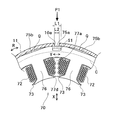
- FIG. 4 is a partially enlarged view of the stator.
- FIG. 5 is a plan view of the core.
- FIG. 6 is a schematic diagram showing the positional relationship between the welding position and the gap.
- FIG. 7 is a graph showing changes in magnetic flux density at each position of the back yoke portion.
- the rotary compressor 1 is a two-cylinder rotary compressor, and includes a sealed casing 10, a motor 20 and a compression mechanism 30 disposed in the sealed casing 10, And an accumulator 40 disposed on the side of the hermetic casing 10.
- the rotary compressor 1 is a so-called high-pressure dome type compressor and uses a CO 2 refrigerant (hereinafter abbreviated as a refrigerant).
- the compression mechanism 30 is disposed below the motor 20 in the sealed casing 10.
- lubricating oil 50 supplied to each sliding portion of the compression mechanism 30 is stored in the lower portion of the hermetic casing 10.
- the hermetic casing 10 includes a pipe 11, a top 12, and a bottom 13.
- the pipe 11 is a substantially cylindrical member extending in the vertical direction, and the upper and lower ends thereof are open. Further, two connection ports 11a and 11b for introducing inlet tubes 43a and 43b, which will be described later, into the inside of the sealed casing 10 are formed on the side surface of the pipe 11 in the vertical direction. And the cylindrical joint pipes 14a and 14b which hold
- the top 12 is a member that closes the opening at the upper end of the pipe 11.
- a discharge pipe 15 for discharging the high-temperature and high-pressure refrigerant compressed by the compression mechanism 30 to the outside of the sealed casing 10 is attached to the top 12.
- the top 12 is provided with a terminal terminal 16 connected to the motor 20.
- the bottom 13 is a member that closes the opening at the lower end of the pipe 11. In the sealed casing 10 having the above-described configuration, a sealed space surrounded by the pipe 11, the top 12, and the bottom 13 is formed.
- the motor 20 is disposed inside the pipe 11, and as shown in FIG. 2, the pipe 11 and the motor 20 are joined by spot welding at three welding positions P1 to P3.
- the pipe 11 is provided with welding holes 10a to 10c at respective portions corresponding to the three welding positions P1 to P3.
- the welding positions P1 to P3 and the welding holes 10a to 10c are provided at an interval of about 120 degrees in the circumferential direction (R direction).
- the pipe 11 and the motor 20 are generally fixed by welding.
- the motor 20 is a concentrated winding motor in which a coil 72 of each phase (U phase, V phase, W phase) is wound around a tooth portion 76 of a core 71.
- the motor 20 is provided to drive a compression mechanism 30 disposed below the motor 20.
- the rotor 60 and a radially outer side of the rotor 60 via an air gap are provided. And a stator 70 to be arranged.
- the rotor 60 has a core 61 and a plurality of permanent magnets 62.
- the core 61 is formed by laminating a plurality of thin plates made of a metal material and joining them together by welding or the like.
- the core 61 is formed with a substantially circular through hole 63 at a substantially central portion in plan view. The upper end portion of the shaft 80 is inserted into the through hole 63, and the shaft 80 is fixed to the core 61.
- the stator 70 has a core 71, a coil 72, a slot cell (insulating member) 73, and insulators 74a and 74b (see FIG. 1).
- the core 71 is formed by laminating a plurality of thin plates made of a metal material and joining them together by welding or the like. As shown in FIG. 5, the core 71 includes an annular back yoke portion 75, nine tooth portions 76 projecting inward in the radial direction (X direction) from the back yoke portion 75, and adjacent tooth portions 76. And nine slots 77 formed between the two.
- a through hole H extending in the vertical direction is formed in a substantially central portion of the core 71. Inside the through hole H, the above-described rotor 60 (see FIG. 3) is arranged.
- the back yoke portion 76 described above has a smaller width in the radial direction (X direction) than the motor in which the coil winding method is distributed winding. ing.
- arc portions 75a that contact the inner peripheral surface of the pipe 11 and core cut portions 75b that do not contact the inner peripheral surface of the pipe 11 alternate along the circumferential direction (R direction).
- the arc portion 75a is formed in a curved surface shape along the inner peripheral surface of the pipe 11, and the core cut portion 75b is formed in a flat surface shape.
- the slot 77 is provided inside the radial direction (X direction) of the arc portion 75a, and the tooth portion 76 is provided inside the radial direction (X direction) of the core cut portion 75b.
- the above-described welding positions P1 to P3 are arranged on the circular arc portion 75a that is in contact with the inner peripheral surface of the pipe 11.
- a gap Q (see FIG. 4) is formed between the core cut portion 75b and the inner peripheral surface of the pipe 11.
- substantially rectangular parallelepiped voids (heat transfer shielding portions) S1 to S3 are provided in the portions corresponding to the welding positions P1 to P3 of the back yoke portion 75, respectively. It has been.
- the gaps S1 to S3 are provided at positions separated from the outer end portion of the back yoke portion 75.
- the space S1 is provided between the welding position P1 and the slot 77a adjacent to the welding position P1
- the space S2 is provided between the welding position P2 and the slot 77b adjacent to the welding position P2, and the space S3. Is provided between the welding position P3 and the slot 77c adjacent to the welding position P3.
- gaps S1 to S3 extend in a direction (Y direction) orthogonal to the radial direction (X direction) in plan view, and as shown in FIG. 4, the longitudinal direction (Y direction) of the gaps S1 to S3 ) Is larger than the opening width L2 in the Y direction of the welding holes 10a to 10c.
- the air gaps S1 to S3 are provided outside the center of the back yoke portion 75 in the radial direction (X direction) (center line C in FIG. 4).
- the change in the magnetic flux density in the radially outer portion of the back yoke portion 75 in which the air gaps S1 to S3 are provided is smaller than that in the radially inner portion of the back yoke portion 75. That is, in the present embodiment, the air gaps S1 to S3 are provided in a portion outside the center in the radial direction of the back yoke portion 75 where the change in magnetic flux density is small.
- This center line C is a line passing through the center of the arcuate portion 75a in the radial direction (X direction) of the back yoke portion 75.
- the entire gaps S1 to S3 are provided in a portion outside the center of the back yoke part 75.
- the present invention is not limited to this, and the centers of the gaps S1 to S3 are the center of the back yoke part 75. You may form so that it may be located in an outer part.
- the depth (the length in the radial direction) of the air gaps S1 to S3 of the present embodiment is less than half the thickness of the back yoke 75, so that the effect of suppressing heat transfer is minimized while minimizing the influence of magnetic flux flow. Can be obtained.
- each of the gaps S1 to S3 is provided only in a portion corresponding to the welding positions P1 to P3 in the vertical direction (Z direction). That is, the gaps S1 to S3 are provided only at the same height as the welding positions P1 to P3, respectively.
- the width H1 in the vertical direction (Z direction) of these voids S1 to S3 is larger than the opening width H2 in the Z direction of the welding holes 10a to 10c.
- a coil 72 of each phase (U phase, V phase, W phase) is wound around each of the nine teeth portions 76. Specifically, the coils 72 of each phase of the U phase, the V phase, and the W phase are wound around the teeth portion 76 in order along the circumferential direction (R direction).
- Each of the nine slots 77 penetrates the core 71 in the vertical direction (Z direction). Each of the nine slots 77 communicates with the through hole H through an opening 77d (see FIG. 4) formed between the tips of the adjacent teeth portions 76.
- the coil 72 described above is wound around each tooth portion 76 by a nozzle (not shown) of a winding machine inserted into the slot 77 through the opening 77d.
- a slot cell 73 for insulating the tooth portion 76 and the coil 72 is inserted.
- the slot cell 73 is a film made of PET (polyethylene terephthalate).
- the slot cell 73 is arranged along the shape of the slot 77.
- the shaft 80 rotates with the rotor 60 described above, thereby rotating the pistons 34 and 37 of the compression mechanism 30.
- the shaft 80 is provided with an eccentric portion 81 so as to be positioned in a cylinder chamber T1 of the front cylinder 33 described later, and is provided with an eccentric portion 82 so as to be positioned in a cylinder chamber T2 of the rear cylinder 36.
- Pistons 34 and 37 are attached to the eccentric parts 81 and 82, respectively, and the piston 34 attached to the eccentric part 81 rotates in the cylinder chamber T1 as the shaft 80 rotates and the eccentric part 82.
- the piston 37 mounted on the cylinder rotates in the cylinder chamber T2.
- the eccentric portion 81 and the eccentric portion 82 are disposed at positions shifted by 180 ° in the rotation direction of the shaft 80.
- the compression mechanism 30 includes a front muffler 31, a front head 32, and a front cylinder 33 having a double structure from the top to the bottom along the rotation axis of the shaft 80 of the motor 20. And a piston 34, a middle plate 35, a rear cylinder 36 and a piston 37, a rear head 38, and a rear muffler 39.
- the front muffler 31 silences the refrigerant discharged from a discharge port (not shown) provided in the front head 32 and discharges it to the primary space.
- the front muffler 31 is attached to the front head 32.
- the front head 32 is joined to the upper surface of the front cylinder 33 and closes the opening at the upper end of the cylinder chamber T1.
- the front head 32 is provided with a discharge port (not shown) for discharging the refrigerant compressed in the cylinder chamber T1 to the muffler space A formed by the front muffler 31 described above.
- the front cylinder 33 is provided with a cylinder chamber T1 at the center thereof.
- a piston 34 that moves eccentrically with the rotation of the shaft 80 is disposed.
- the cylinder chamber T1 communicates with the muffler space A through the above-described discharge port. Therefore, the refrigerant compressed by the eccentric rotational movement of the piston 34 attached to the eccentric portion 81 of the shaft 80 is guided from the cylinder chamber T1 to the muffler space A.
- the piston 34 performs an eccentric rotational movement along the inner peripheral surface of the cylinder chamber T1, and compresses the refrigerant sucked from the accumulator 40.
- the middle plate 35 is disposed between the front cylinder 33 and the rear cylinder 36.
- the middle plate 35 closes the opening below the cylinder chamber T1 of the front cylinder 33 and closes the opening above the cylinder chamber T2 of the rear cylinder 36.
- the rear cylinder 36, the piston 37, the rear head 38, and the rear muffler 39 are the same as the front cylinder 33, the piston 34, the front head 32, and the front muffler 31, respectively, in view of their functions.
- the refrigerant compressed in the cylinder chamber T2 of the rear cylinder 36 passes through a muffler space (not shown) formed by the rear head 38 and the rear muffler 39, and then the rear head 38, the rear cylinder 36, the middle plate 35, and the front
- the air is guided to the muffler space A through a communication hole (not shown) communicating with the cylinder 33 and an introduction port (not shown) formed in the front head 32.
- the accumulator 40 is provided to supply refrigerant from the outside of the hermetic casing 10 to each of the cylinder chamber T1 of the front cylinder 33 and the cylinder chamber T2 of the rear cylinder 36 disposed therein.
- the accumulator 40 includes an inlet pipe 41 extending in the vertical direction and two outlet pipes 42a and 42b bent in a substantially L shape. Thereby, the refrigerant flowing in from the inlet pipe 41 passes through the outlet pipes 42a and 42b and is supplied to the cylinder chambers T1 and T2, respectively.
- substantially cylindrical inlet tubes 43a and 43b are connected to the respective ends of the outlet pipes 42a and 42b.
- the inlet tubes 43a and 43b are connected to cylinders 33 and 36 via joint pipes 14a and 14b joined to the sealed casing 10, respectively.
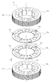
- FIG. 8 is an exploded perspective view for explaining a method of manufacturing the core of the compressor according to the first embodiment of the present invention. Next, with reference to FIG. 8, the manufacturing method of the core of the compressor which concerns on 1st Embodiment is demonstrated.
- the core 71 is formed by laminating a plurality of thin plates made of a metal material as described above and joining them together by welding or the like.
- the core 71 since the substantially rectangular parallelepiped gaps S1 to S3 are provided in a part of the back yoke portion 75 in the vertical direction (Z direction), the core 71 cannot be configured only by thin plates having the same shape. Therefore, in the present embodiment, as shown in FIG. 7, two types of thin plates, that is, a plurality of thin plates 71a having through holes 71c forming the gaps S1 to S3, and a plurality of thin plates 71b having no through holes are provided. Prepare.
- a portion U1 corresponding to the lower portion of the core 71 is formed by laminating a plurality of thin plates 71b having no through holes. Next, the through-holes are formed in the above-described portion U1 so that the gaps S1 to S3 are formed at predetermined height positions (portions corresponding to the welding positions P1 to P3 (see FIG. 6) with respect to the vertical direction (Z direction)).
- a plurality of thin plates 71a having 71c are laminated. The number of the thin plates 71a is determined according to the width H1 (see FIG. 6) in the vertical direction (Z direction) of the gaps S1 to S3.
- the core 71 is completed in which the gaps S1 to S3 are provided only in the portions corresponding to the welding positions P1 to P3 (see FIG. 6) in the vertical direction (Z direction).
- the compressor 1 of this embodiment has the following characteristics.
- the compressor 1 of the present embodiment by providing the gaps S1 to S3 in the portions corresponding to the welding positions P1 to P3 of the back yoke portion 75, it is possible to shield the heat during welding from being transmitted to the slot cell 73. it can. Thereby, it is possible to prevent the slot cell 73 from melting.
- each of the air gaps S1 to S3 is provided between the welding positions P1 to P3 and the slots 77a to 77c adjacent to the welding positions P1 to P3, so that the welding position It is possible to prevent the slot cell 73 from melting in the slot 77 where heat from P1 to P3 is most easily transferred.
- the gaps S1 to S3 are provided only in portions corresponding to the welding positions P1 to P3 in the vertical direction (Z direction), thereby limiting the range in which the gaps S1 to S3 are provided.
- the width L1 in the direction (Y direction) perpendicular to the radial direction (X direction) of the air gaps S1 to S3 is orthogonal to the radial direction (X direction) of the welding hole 10a in plan view.
- the air gaps S1 to S3 are arranged outside the center in the radial direction of the back yoke portion 75 where the change in magnetic flux density is small, so that the flow of magnetic flux due to the air gaps S1 to S3 The influence can be suppressed.
- the compressor 1 of the present embodiment by providing the gaps S1 to S3, distortion due to thermal expansion or shrinkage stress during welding can be absorbed in the gaps S1 to S3, so that deformation of the core 71 is reduced. can do. Thereby, the rotor 60 can be arrange
- the electromagnetic vibration of the motor 20 can be absorbed by the gaps S1 to S3, so that the vibration transmitted to the hermetic casing 10 can be suppressed, and low noise and vibration are reduced. Can be realized.
- the compressor 1 of the present embodiment it is possible to suppress melting of the slot cell 73 with a simple configuration in which the gaps S1 to S3 are provided without using a special member that shields heat transfer.
- the slot cell 73 of a film that is easily melted against heat is used, in the compressor 1 of the present embodiment that suppresses heat transfer to the slot cell, the slot cell 73 is prevented from melting. Can do. Thereby, the range of material selection of the slot cell 73 is expanded.
- the gap Q is formed between the core cut portion 75b and the pipe 11, so that the heat radiation from the core 71 to the outside through the pipe 11 is not promoted and the slot cell. Since the problem that the 73 melts appears remarkably, the compressor 1 that suppresses heat transfer to the slot cell 73 is particularly effective.
- the compressor 1 that suppresses heat transfer to the slot cell 73 is particularly effective.
- the casing and the motor are generally joined by welding, so that the compressor 1 that suppresses heat transfer to the slot cell 73 is particularly effective.
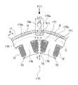
- FIG. 9 is a partially enlarged view of the stator according to the second embodiment of the present invention.
- a stator 170 according to the second embodiment of the present invention will be described in detail with reference to FIG.
- the configuration other than the air gap S11 provided in the back yoke portion 175 of the core 171 is the same as that in the first embodiment, and thus the description thereof is omitted as appropriate.
- the core 171 is formed by laminating a plurality of thin plates made of metal materials and joining them together by welding or the like. As shown in FIG. 9, the core 171 includes an annular back yoke portion 175, a plurality of tooth portions 176 that protrude radially inward (X direction) from the back yoke portion 175, and adjacent tooth portions 176. And a slot 177 formed therebetween.
- arc portions 175a that contact the inner peripheral surface of the pipe 11 and core cut portions 175b that do not contact the inner peripheral surface of the pipe 11 alternate along the circumferential direction (R direction).
- a slot 177 is provided inside the radial direction (X direction) of the arc portion 175a
- a teeth portion 176 is provided inside the radial direction (X direction) of the core cut portion 175b.
- the welding position P11 is arrange
- a gap Q is formed between the core cut portion 175 b and the inner peripheral surface of the pipe 11.
- a gap (heat transfer shielding portion) S11 is provided in a portion corresponding to the welding position P11 of the back yoke portion 175.
- the gap S11 is a position spaced from the outer end of the back yoke portion 175, and is provided between the welding position P11 and the slot 177 adjacent to the welding position P11.
- the space S11 extends in a direction (Y direction) orthogonal to the radial direction (X direction) in plan view, and a width L11 in the longitudinal direction (Y direction) of the space S11 is the Y direction of the weld hole 10a. Is larger than the opening width L2.
- both end portions in the longitudinal direction (Y direction) of the gap S11 are tapered.
- the air gap S11 is provided at a portion outside the center (center line C in the drawing) of the back yoke portion 175 in the radial direction (X direction).
- the portion of the back yoke portion 175 in the radial direction where the air gap S11 is provided has a smaller change in magnetic flux density than the portion of the back yoke portion 175 in the radial direction.
- a gap S11 is provided in a portion outside the radial center of the back yoke portion 175 where the density change is small.
- the compressor of this embodiment has the following features.
- Providing the air gap (heat transfer shielding part) S11 has an effect of preventing the flow of magnetic flux, but in this compressor, the magnetic flux flows smoothly by tapering both ends of the air gap S11 in the Y direction. And the influence can be suppressed.
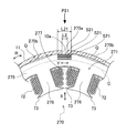
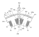
- FIG. 10 is a partially enlarged view of a stator according to the third embodiment of the present invention.
- the stator 270 which concerns on 3rd Embodiment of this invention is demonstrated in detail.
- the configuration other than the air gap S21 provided in the back yoke portion 275 of the core 271 is the same as that in the first and second embodiments, and thus the description thereof is omitted as appropriate.
- the core 271 is formed by laminating a plurality of thin plates made of metal materials and joining them together by welding or the like. As shown in FIG. 10, the core 271 includes an annular back yoke portion 275, a plurality of teeth portions 276 projecting inward in the radial direction (X direction) from the back yoke portion 275, and adjacent teeth portions 276. And a slot 277 formed therebetween.
- arc portions 275a that contact the inner peripheral surface of the pipe 11 and core cut portions 275b that do not contact the inner peripheral surface of the pipe 11 alternate along the circumferential direction (R direction).
- a slot 277 is provided inside the radial direction (X direction) of the arc portion 275a
- a tooth portion 276 is provided inside the radial direction (X direction) of the core cut portion 275b.
- the welding position P21 is arrange
- a gap Q is formed between the core cut part 275b and the inner peripheral surface of the pipe 11.
- each of these gaps S21 is provided at a position spaced from the outer end portion of the back yoke portion 275 and between the welding position P21 and the slot 277 adjacent to the welding position P21.
- Each of these gaps S21 extends in a direction (Y direction) orthogonal to the radial direction (X direction) in plan view, and a width L21 in the longitudinal direction (Y direction) of the gap S21 is equal to the weld hole 10a. Is larger than the opening width L2 in the Y direction.
- these gaps S21 are all provided in a portion outside the center (center line C in the drawing) in the radial direction (X direction) of the back yoke portion 275.
- the portion of the back yoke portion 275 in the radial direction where the air gap S21 is provided has a smaller change in magnetic flux density than the portion of the back yoke portion 275 in the radial direction.
- the magnetic flux density A plurality of gaps S ⁇ b> 21 are provided in the portion outside the center in the radial direction of the back yoke portion 275 where the change is small.
- the compressor of this embodiment has the following features.
- the surface area of the air gap S21 can be increased as compared with the case of using one air gap. Thereby, the heat dissipation in the said space
- FIG. 11 is a partially enlarged view of a stator according to the fourth embodiment of the present invention.
- the stator 370 which concerns on 4th Embodiment of this invention is demonstrated in detail.
- the configuration other than the heat transfer shielding portion provided in the back yoke portion 375 of the core 371 is the same as that in the first to third embodiments, and thus the description thereof is omitted as appropriate.
- the core 371 is formed by laminating a plurality of thin plates made of a metal material and joining them together by welding or the like. As shown in FIG. 11, the core 371 includes an annular back yoke portion 375, a plurality of teeth portions 376 that protrude inward in the radial direction (X direction) from the back yoke portion 375, and adjacent tooth portions 376. And a slot 377 formed therebetween.
- arc portions 375a that contact the inner peripheral surface of the pipe 11 and core cut portions 375b that do not contact the inner peripheral surface of the pipe 11 alternate along the circumferential direction (R direction).
- a slot 377 is provided inside the radial direction (X direction) of the arc portion 375a
- a teeth portion 376 is provided inside the radial direction (X direction) of the core cut portion 375b.
- the welding position P31 is arrange
- a gap Q is formed between the core cut portion 375b and the inner peripheral surface of the pipe 11.
- a substantially rectangular parallelepiped concave portion (heat transfer shielding portion) S31 communicating with the slot 377 is provided in a portion corresponding to the welding position P31 of the back yoke portion 375.
- the recess S31 is formed in a portion of the back yoke portion 375 facing the slot 377.
- the recess S31 is provided at a position spaced from the outer end of the back yoke portion 375 and between the welding position P31 and the slot 377 adjacent to the welding position P31.
- Each of the recesses S31 extends in a direction (Y direction) orthogonal to the radial direction (X direction) in plan view, and a width L31 in the longitudinal direction (Y direction) of the recess S31 is equal to that of the welding hole 10a. It is larger than the opening width L2 in the Y direction.
- the compressor of this embodiment has the following features.
- the slot cell 73 does not come into contact with the back yoke portion 375 by providing the concave portion S31 in the portion facing the slot 377 of the back yoke portion 375. It is possible to further prevent the slot cell 73 from being melted by being transmitted.
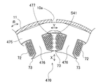
- FIG. 12 is a partially enlarged view of a stator according to the first modification of the fourth embodiment of the present invention
- FIG. 13 is a partially enlarged view of the stator according to the second modification of the fourth embodiment of the present invention.
- FIG. in the fourth embodiment described above the example in which the substantially rectangular parallelepiped concave portion S31 is provided in the back yoke portion 375 has been described.
- the present invention is not limited to this, and the first modification of the fourth embodiment shown in FIG.
- the recess S41 formed in the portion facing the slot 477 of the back yoke portion 475 may be formed so that both ends in the Y direction are tapered.
- two recesses S51a and S51b may be provided for one slot 577.
- the convex part S51c is formed between the concave parts S51a and S51b by arranging the concave parts S51a and S51b at a predetermined interval in the Y direction.
- the slot cell 73 disposed in the slot 577 can be supported by the projection S51c provided between the adjacent recess S51a and the recess S51b so as not to bend.
- the slot cell 73 can be prevented from being arranged in a bent state.
- FIG. 14 is a partially enlarged view of a stator according to the fifth embodiment of the present invention.
- the stator 670 which concerns on 5th Embodiment of this invention is demonstrated in detail.
- the configuration other than the stator 670 is the same as that of the first embodiment, the description thereof is omitted as appropriate.
- the core 671 is formed by laminating a plurality of thin plates made of a metal material and joining them together by welding or the like. As shown in FIG. 14, the core 671 includes an annular back yoke portion 675, a plurality of teeth portions 676 protruding inward in the radial direction (X direction) from the back yoke portion 675, and adjacent teeth portions 676. And a slot 677 formed therebetween.
- arc portions 675a that contact the inner peripheral surface of the pipe 11 and core cut portions 675b that do not contact the inner peripheral surface of the pipe 11 alternate along the circumferential direction (R direction).
- the tooth portion 676 is provided inside the radial direction (X direction) of the arc portion 675a
- the slot 677 is provided inside the radial direction (X direction) of the core cut portion 675b.
- the welding position P61 is arrange
- a gap Q is formed between the core cut portion 675b and the inner peripheral surface of the pipe 11.
- a gap (heat transfer shielding portion) S61 is provided in a portion corresponding to the welding position P61 of the back yoke portion 675.
- the gap S61 is provided at a position separated from the outer end of the back yoke portion 675 and between the welding position P61 and the slot 677 adjacent to the welding position P61.
- the slots 677 (677a and 677b) close to the welding position P61 are provided on both sides of the tooth portion 676 close to the welding position P61, the gap S61 is formed at the welding position P61. And the slot 677a, and a position between the welding position P61 and the slot 677b.
- FIG. 15 is a partially enlarged view of a stator according to a first modified example of the fifth embodiment of the present invention
- FIG. 16 is a partially enlarged view of a stator according to the second modified example of the fifth embodiment of the present invention.
- FIG. 15 an example in which the gap S61 having the same shape, size, and range as the gap S1 of the first embodiment is provided outside in the radial direction (X direction) of the tooth portion 676 has been described.
- X direction radial direction
- both ends in the Y direction are tapered.
- the three gaps S81 provided may be provided in the back yoke portion 875 located outside the teeth portion 876 in the radial direction (X direction).
- FIG. 17 is a partially enlarged view of a stator according to the sixth embodiment of the present invention.
- the stator 970 which concerns on 6th Embodiment of this invention is demonstrated in detail.
- the configuration other than the heat transfer shielding portion provided on the back yoke portion 975 of the core 971 is the same as that of the fifth embodiment, and thus the description thereof is omitted as appropriate.
- the core 971 is formed by laminating a plurality of thin plates made of a metal material and joining them together by welding or the like. As shown in FIG. 17, the core 971 includes an annular back yoke portion 975, a plurality of teeth portions 976 projecting inward in the radial direction (X direction) from the back yoke portion 975, and adjacent teeth portions 976. And a slot 977 formed therebetween.
- arc portions 975a that contact the inner peripheral surface of the pipe 11 and core cut portions 975b that do not contact the inner peripheral surface of the pipe 11 alternate along the circumferential direction (R direction).
- a tooth portion 976 is provided inside the radial direction (X direction) of the arc portion 975a
- a slot 977 is provided inside the radial direction (X direction) of the core cut portion 975b.
- the welding position P91 is arrange
- a gap Q is formed between the core cut part 975b and the inner peripheral surface of the pipe 11.
- a substantially rectangular parallelepiped concave portion (heat transfer shielding portion) S91 (91a and 91b) is provided in a portion corresponding to the welding position P91 of the back yoke portion 975.
- the recess S91 is a position spaced from the outer end of the back yoke portion 975, and is provided between the welding position P91 and the slot 977 adjacent to the welding position P91. That is, in the sixth embodiment, since the slots 977 (977a and 977b) close to the welding position P91 are provided on both sides of the tooth portion 976 close to the welding position P91, the recess S91a is formed at the welding position P91. And the slot 977a, and the recess S91b is provided between the welding position P91 and the slot 977b.
- FIG. 18 is a partially enlarged view of a stator according to a first modification of the sixth embodiment of the present invention
- FIG. 19 is a partially enlarged view of a stator according to the second modification of the sixth embodiment of the present invention.
- FIG. in the above-described sixth embodiment the example in which the substantially rectangular parallelepiped concave portion S91 is provided in the back yoke portion 975 has been described.
- the present invention is not limited thereto, and the first modification example of the sixth embodiment illustrated in FIG.
- the concave portions S101a whose both ends in the Y direction are tapered are provided between the welding position P101 and the slot 1077a, and in the Y direction.
- a concave portion S101b whose both end portions are tapered may be provided between the welding position P101 and the slot 1077b.
- two recesses are provided for one slot, as in the second modification of the fourth embodiment. Also good.
- two recesses S111a and S111b are provided for the slot 1177a disposed on one side of the tooth portion 1176, and two recesses S111c and S111d are provided for the slot 1177b disposed on the other side of the tooth portion 1176.
- convex part S111e is formed between recessed part S111a and S111b by providing recessed part S111a and S111b at predetermined intervals.
- a projection S111f is formed between the recesses S111c and S111d. Accordingly, the slot cells 73 arranged in the slots 1177a and 1177b can be supported by the convex portions S111e and 111f so as not to bend. As a result, it is possible to prevent the slot cell 73 from being arranged in a bent state.
- the present invention is not limited to this, and may be applied to a one-cylinder compressor or a compressor having three or more cylinders.
- the present invention is applicable.
- the present invention is not limited to this, also to the compressor utilizing a refrigerant other than the CO 2 refrigerant can be applied to the present invention.
- slot cell of a film made of PET is shown, but the present invention is not limited to this, and the material of the slot cell is not limited to PET.
- a slot cell that is permeable to oil and / or refrigerant may also be used.
- the slot cell since the slot cell is cooled by the oil and / or refrigerant that has penetrated into the slot cell, it is possible to further suppress melting of the slot cell.
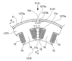
- the said embodiment demonstrated the example which has arrange
- the welding position P121 may be disposed in the core cut portion 1275b.
- a convex portion 1275c protruding outward from the core cut portion 1275b in the radial direction (X direction) is disposed in the weld hole 10a of the pipe 11.
- gap S121 is a part corresponding to the welding position P121 of the back yoke part 1275, Comprising: It is provided inside the radial direction (X direction) of the said convex part 1275c.
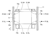
- the said embodiment demonstrated the example (refer FIG. 6) which arrange
- the welding positions P13H and P13L may be arranged at different height positions.
- the gaps (heat transfer shielding portions) S13H and S13L are provided so as to correspond to the welding positions P13H and P13L.
- the present invention is not limited to this, and a stator 1470 according to the modification shown in FIG.
- a gap (heat transfer shielding portion) S141 having both circular ends in the Y direction may be provided.
- both ends of the gap S141 in the Y direction have a circular shape, the magnetic flux smoothly flows. Therefore, the influence of obstructing the flow of the magnetic flux by providing the gap S141 can be suppressed.
- gap and the recessed part demonstrated the example extended in the direction (Y direction) orthogonal to radial direction (X direction)
- this invention is not limited to this,
- gap and The recessed part should just extend in the direction which cross
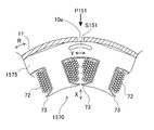
- the gap corresponds to the welding position P151 of the back yoke portion 1575.
- a gap (heat transfer shielding portion) S151 that is curved in an arc shape can be provided in the portion to be performed.
- the present invention is not limited to this, and the gap S1 ⁇ S3 may be formed so as to penetrate in the vertical direction (Z direction).
- the coil is cooled, so that the efficiency is improved and the reliability of the coil is improved.
- Compressor 11 Pipe (casing) 20 Motor 71,171,271,371,671,971 Core 72 Coil 73 Slot cell (insulating member) 75,175,275,375,475,575,675,775,875,975,1075,1175,1275,1475,1575 Back yoke part 76,176,276,376,676,776,876,976,1176 teeth Portions 77, 77a, 77b, 77c, 177, 277, 377, 477, 577, 677, 977, 1077a, 1077b, 1177a, 1177b Slots S1, S2, S3, S11, S21, S61, S71, S81, S91, S101a , S101b, S121, S13H, S13L, S141, S151 Air gap (heat transfer shielding part) S31, S41, S51a, S51b, S91a, S91b, S111a, S111b, S111c, S111d Recess (heat transfer
Landscapes
- Engineering & Computer Science (AREA)
- Mechanical Engineering (AREA)
- General Engineering & Computer Science (AREA)
- Power Engineering (AREA)
- Manufacturing & Machinery (AREA)
- Compressor (AREA)
- Applications Or Details Of Rotary Compressors (AREA)
- Insulation, Fastening Of Motor, Generator Windings (AREA)
Abstract
スロットに配置される絶縁部材が融けるのを抑制する。 この圧縮機は、パイプ11とそのパイプ11の内部に配置されるモータとを複数の溶接位置P1~P3で溶接により接合する圧縮機である。モータは、環状のバックヨーク部75、バックヨーク部75から径方向(X方向)の内側に突出する複数のティース部76、及び、隣接するティース部76の間に形成されるスロット77を有するコア71と、スロット77に配置されるコイル72と、スロット77に配置され、コイル72とコア71とを絶縁するスロットセル73とを備えている。バックヨーク部75の複数の溶接位置P1~P3に対応する部分には、それぞれ空隙(伝熱遮蔽部)S1~S3が設けられている。
Description
本発明は、ケーシングとそのケーシングの内部に配置されるモータとを複数の溶接位置で溶接により接合する圧縮機に関する。
従来、ケーシングに対するモータの固定方法として、ケーシングとそのケーシングの内部に配置されるモータとを溶接により接合する圧縮機が種々提案されている(例えば、特許文献1及び2参照)。
しかしながら、バックヨーク部とケーシングとを溶接により接合する場合、溶接時の熱がバックヨーク部に伝達し、スロットに配置される絶縁部材を融かしてしまうという不都合がある。特に、集中巻きのモータでは、分布巻きのモータに比べて、バックヨーク部の厚みが小さく、溶接時の熱が絶縁部材に伝達し易いので、絶縁部材が融けるという問題が顕著に現れる。
そこで、この発明は、上記のような課題を解決するためになされたものであり、スロットに配置される絶縁部材が融けるのを抑制することが可能な圧縮機を提供することを目的とする。
第1の発明にかかる圧縮機は、ケーシングとそのケーシングの内部に配置されるモータとを複数の溶接位置で溶接により接合する圧縮機において、モータは、環状のバックヨーク部、バックヨーク部から径方向の内側に突出する複数のティース部、及び、隣接するティース部の間に形成されるスロットを有するコアと、スロットに配置されるコイルと、スロットに配置され、コイルとコアとを絶縁する絶縁部材とを備え、バックヨーク部の複数の溶接位置に対応する部分の少なくとも1つには、伝熱遮蔽部が設けられている。
この圧縮機では、伝熱遮蔽部により溶接時の熱が絶縁部材に伝達するのを遮蔽することができるので、当該絶縁部材が融けてしまうのを抑制することができる。
第2の発明にかかる圧縮機は、第1の発明にかかる圧縮機において、伝熱遮蔽部は、溶接位置とその溶接位置に近接するスロットとの間に設けられる。
この圧縮機では、溶接位置からの熱が最も伝熱し易い当該スロットにおいて、絶縁部材が融けてしまうのを抑制することができる。
第3の発明にかかる圧縮機は、第1又は第2の発明にかかる圧縮機において、伝熱遮蔽部は、上下方向に関して溶接位置に対応する部分にのみに設けられる。
伝熱遮蔽部を設けることで磁束の流れを妨げるという影響が生じてしまうが、この圧縮機では、伝熱遮蔽部を設ける範囲を限定することにより、その影響を最小限に抑えることができる。
第4の発明にかかる圧縮機は、第1~第3のいずれかの発明にかかる圧縮機において、平面視において、伝熱遮蔽部は、径方向に交差する方向に延在し、その延在する方向の端部が先細形状又は円形状である。
伝熱遮蔽部を設けることで磁束の流れを妨げるという影響が生じてしまうが、この圧縮機では、伝熱遮蔽部の端部を先細形状又は円形状にすることで磁束が円滑に流れるようになり、その影響を抑えることができる。
第5の発明にかかる圧縮機は、第1~第4のいずれかの発明にかかる圧縮機において、ケーシングには、溶接位置に対応する部分に溶接孔が設けられ、平面視において、伝熱遮蔽部の径方向に交差する方向の幅は、溶接孔の径方向に交差する方向の幅より大きい。
この圧縮機では、溶接に係る熱の放射範囲を当該伝熱遮蔽部で覆うことができるので、絶縁部材が融ける可能性がある箇所を広範囲にカバーすることができる。
第6の発明にかかる圧縮機は、第1~第5のいずれかの発明にかかる圧縮機において、伝熱遮蔽部は、径方向に沿って間隔を隔てて複数設けられている。
この圧縮機では、伝熱遮蔽部の表面積が大きくなるので、当該伝熱遮蔽部における放熱性が増大し、絶縁部材への伝熱をより抑制することができる。
第7の発明にかかる圧縮機は、第1~第6のいずれかの発明にかかる圧縮機において、伝熱遮蔽部は、バックヨーク部の径方向中央より外側の部分に配置される。
バックヨーク部では、径方向外側の部分ほど磁束密度変化が小さくなり、バックヨーク部の径方向中央から外側に向かって磁束密度変化が急激に低下している。従って、この圧縮機では、伝熱遮蔽部をバックヨーク部の径方向中央より外側の部分に配置することによって、伝熱遮蔽部による磁束の流れの影響を抑えることができる。
第8の発明にかかる圧縮機は、第1~第7のいずれかの発明にかかる圧縮機において、伝熱遮蔽部は、バックヨーク部の外端部から離間した位置に設けられる空隙、又は、バックヨーク部のスロットに面する部分に形成される凹部である。
この圧縮機では、空隙を設けるという簡単な構成で絶縁部材が融けてしまうのを抑制することができる。
また、凹部を設けた場合には、絶縁部材がバックヨーク部に接触しなくなるので、溶接による熱が直接絶縁部材に伝達しなくなり、絶縁部材が融けてしまうのをより抑制することができる。
さらに、この圧縮機では、空隙又は凹部を設けることにより、溶接時の熱膨張や収縮応力による歪みを当該空隙又は凹部において吸収することができるので、コアの変形を軽減することができる。これにより、コアの内部に配置される回転子とコアとの間のエアギャップが均一になり、磁束がアンバランスになるのを抑制することができる。その結果、電磁加振力が発生するのを抑制することができ、振動及びその振動による騒音が発生するのを抑制することができる。
また、当該空隙又は凹部が油や冷媒の通路となる場合、コイルが冷却されるため圧縮機の効率が向上すると共にコイルの信頼性が向上する。
また、モータの電磁振動を当該空隙又は凹部によって吸収することができるので、ケーシングに伝達される振動を抑えることが可能となり、低騒音及び低振動の圧縮機を得ることができる。
また、凹部を設けた場合には、絶縁部材がバックヨーク部に接触しなくなるので、溶接による熱が直接絶縁部材に伝達しなくなり、絶縁部材が融けてしまうのをより抑制することができる。
さらに、この圧縮機では、空隙又は凹部を設けることにより、溶接時の熱膨張や収縮応力による歪みを当該空隙又は凹部において吸収することができるので、コアの変形を軽減することができる。これにより、コアの内部に配置される回転子とコアとの間のエアギャップが均一になり、磁束がアンバランスになるのを抑制することができる。その結果、電磁加振力が発生するのを抑制することができ、振動及びその振動による騒音が発生するのを抑制することができる。
また、当該空隙又は凹部が油や冷媒の通路となる場合、コイルが冷却されるため圧縮機の効率が向上すると共にコイルの信頼性が向上する。
また、モータの電磁振動を当該空隙又は凹部によって吸収することができるので、ケーシングに伝達される振動を抑えることが可能となり、低騒音及び低振動の圧縮機を得ることができる。
第9の発明にかかる圧縮機は、第8の発明にかかる圧縮機において、凹部は、一つのスロットに対して複数設けられる。
この圧縮機では、隣接する凹部の間に設けられる部分でスロットに配置される絶縁部材を支持することができるので、凹部を設けたとしても絶縁部材が撓んだ状態で配置されるのを防止することができる。
第10の発明にかかる圧縮機は、第1~第9のいずれかの発明にかかる圧縮機において、絶縁部材は、フィルムである。
熱に対して融け易いフィルムを用いた場合でも、この圧縮機では、当該フィルムが融けてしまうのを抑制することができる。その結果、絶縁部材として使用可能な材料の幅が広がる。
第11の発明にかかる圧縮機は、第1~第10のいずれかの発明にかかる圧縮機において、絶縁部材は、油及び/又は冷媒に対して浸透性がある。
この圧縮機では、絶縁部材の内部に浸透した油及び/又は冷媒により絶縁部材が冷却されるので、当該絶縁部材が融けてしまうのをより抑制することができる。
第12の発明にかかる圧縮機は、第1~第11のいずれかの発明にかかる圧縮機において、絶縁部材は、その内部に気泡を有する。
この圧縮機では、絶縁部材の内部の気泡により絶縁部材が冷却されるので、当該絶縁部材が融けてしまうのをより抑制することができる。
第13の発明にかかる圧縮機は、第1~第12のいずれかの発明にかかる圧縮機において、ケーシングとバックヨーク部の外周面との間には、隙間が設けられている。
ケーシングとバックヨーク部の外周面との間に隙間を形成すると、コアからケーシングを介した外部への放熱が促進されなくなるので、絶縁部材への伝熱抑制を図る本発明は特に有効となる。
第14の発明にかかる圧縮機は、第1~第13のいずれかの発明にかかる圧縮機において、コイルの巻線方式が集中巻きである。
分布巻きのモータに比べて集中巻きのモータではバックヨーク部の径方向の幅が小さく絶縁部材が融けてしまうという問題が顕著に現れるため、絶縁部材への伝熱抑制を図る本発明は、コイルの巻線方式が集中巻きの圧縮機に特に有効となる。
第15の発明にかかる圧縮機は、第1~第14のいずれかの発明に係る圧縮機において、CO2冷媒を用いている。
CO2冷媒を用いた圧縮機では、ケーシングとモータとを複数の溶接位置で溶接により接合することが一般的であるので、絶縁部材への伝熱抑制を図る本発明は、CO2冷媒を用いた圧縮機に特に有効となる。
以上の説明に述べたように、本発明によれば、以下の効果が得られる。
第1の発明では、伝熱遮蔽部により溶接時の熱が絶縁部材に伝達するのを遮蔽することができるので、当該絶縁部材が融けてしまうのを抑制することができる。
また、第2の発明では、溶接位置からの熱が最も伝熱し易い当該スロットにおいて、絶縁部材が融けてしまうのを抑制することができる。
また、第3の発明では、伝熱遮蔽部を設ける範囲を限定することにより、その影響を最小限に抑えることができる。
また、第4の発明では、伝熱遮蔽部の端部を先細形状又は円形状にすることで磁束が円滑に流れるようになり、その影響を抑えることができる。
また、第5の発明では、溶接に係る熱の放射範囲を当該伝熱遮蔽部で覆うことができるので、絶縁部材が融ける可能性がある箇所を広範囲にカバーすることができる。
また、第6の発明では、伝熱遮蔽部の表面積が大きくなるので、当該伝熱遮蔽部における放熱性が増大し、絶縁部材への伝熱をより抑制することができる。
また、第7の発明では、バックヨーク部の径方向外側の部分ほど磁束密度変化が小さくなっていることから(図7参照)、伝熱遮蔽部をバックヨーク部の径方向中央より外側の部分に配置することによって、伝熱遮蔽部による磁束の流れの影響を抑えることができる。
また、第8の発明では、空隙を設けるという簡単な構成で絶縁部材が融けてしまうのを抑制することができる。
また、凹部を設けた場合には、絶縁部材がバックヨーク部に接触しなくなるので、溶接による熱が直接絶縁部材に伝達しなくなり、絶縁部材が融けてしまうのをより抑制することができる。
さらに、この圧縮機では、空隙又は凹部を設けることにより、溶接時の熱膨張や収縮応力による歪みを当該空隙又は凹部において吸収することができるので、コアの変形を軽減することができる。これにより、コアの内部に配置される回転子とコアとの間のエアギャップが均一になり、磁束がアンバランスになるのを抑制することができる。その結果、電磁加振力が発生するのを抑制することができ、振動及びその振動による騒音が発生するのを抑制することができる。
また、当該空隙又は凹部が油や冷媒の通路となる場合、コイルが冷却されるため圧縮機の効率が向上すると共にコイルの信頼性が向上する。
また、モータの電磁振動を当該空隙又は凹部によって吸収することができるので、ケーシングに伝達される振動を抑えることが可能となり、低騒音及び低振動の圧縮機を得ることができる。
また、凹部を設けた場合には、絶縁部材がバックヨーク部に接触しなくなるので、溶接による熱が直接絶縁部材に伝達しなくなり、絶縁部材が融けてしまうのをより抑制することができる。
さらに、この圧縮機では、空隙又は凹部を設けることにより、溶接時の熱膨張や収縮応力による歪みを当該空隙又は凹部において吸収することができるので、コアの変形を軽減することができる。これにより、コアの内部に配置される回転子とコアとの間のエアギャップが均一になり、磁束がアンバランスになるのを抑制することができる。その結果、電磁加振力が発生するのを抑制することができ、振動及びその振動による騒音が発生するのを抑制することができる。
また、当該空隙又は凹部が油や冷媒の通路となる場合、コイルが冷却されるため圧縮機の効率が向上すると共にコイルの信頼性が向上する。
また、モータの電磁振動を当該空隙又は凹部によって吸収することができるので、ケーシングに伝達される振動を抑えることが可能となり、低騒音及び低振動の圧縮機を得ることができる。
また、第9の発明では、隣接する凹部の間に設けられる部分でスロットに配置される絶縁部材を支持することができるので、凹部を設けたとしても絶縁部材が撓んだ状態で配置されるのを防止することができる。
また、第10の発明では、フィルムが融けてしまうのを抑制することができる。その結果、絶縁部材として使用可能な材料の幅が広がる。
また、第11の発明では、絶縁部材の内部に浸透した油及び/又は冷媒により絶縁部材が冷却されるので、当該絶縁部材が融けてしまうのをより抑制することができる。
また、第12の発明では、絶縁部材の内部の気泡により絶縁部材が冷却されるので、当該絶縁部材が融けてしまうのをより抑制することができる。
また、第13の発明では、隙間が形成されることにより、コアからケーシングを介した外部への放熱が促進されなくなるので、絶縁部材への伝熱抑制を図る本発明は特に有効となる。
また、第14の発明では、分布巻きのモータに比べて集中巻きのモータではバックヨーク部の径方向の幅が小さく絶縁部材が融けてしまうという問題が顕著に現れるため、絶縁部材への伝熱抑制を図る本発明は、コイルの巻線方式が集中巻きの圧縮機に特に有効となる。
また、第15の発明では、ケーシングとモータとを複数の溶接位置で溶接により接合することが一般的なCO2冷媒を用いた圧縮機に特に有効となる。
以下、図面に基づいて、本発明に係るCO2冷媒用ロータリー圧縮機の実施形態について説明する。
(第1実施形態)
図1は、本発明の第1実施形態に係るCO2冷媒用ロータリー圧縮機の内部構造を示した断面図である。図2は、圧縮機の水平断面図である。図3は、モータの平面図である。図4は、固定子の部分拡大図である。図5は、コアの平面図である。図6は、溶接位置と空隙との位置関係を示した模式図である。図7は、バックヨーク部の各位置における磁束密度の変化を示したグラフである。以下、図1~図7を参照して、本発明の第1実施形態に係る圧縮機1について詳細に説明する。
図1は、本発明の第1実施形態に係るCO2冷媒用ロータリー圧縮機の内部構造を示した断面図である。図2は、圧縮機の水平断面図である。図3は、モータの平面図である。図4は、固定子の部分拡大図である。図5は、コアの平面図である。図6は、溶接位置と空隙との位置関係を示した模式図である。図7は、バックヨーク部の各位置における磁束密度の変化を示したグラフである。以下、図1~図7を参照して、本発明の第1実施形態に係る圧縮機1について詳細に説明する。
<ロータリー圧縮機の全体構成>
第1実施形態に係るロータリー圧縮機1は、図1に示すように、2シリンダ型ロータリー圧縮機であって、密閉ケーシング10と、密閉ケーシング10内に配置されるモータ20及び圧縮機構30と、密閉ケーシング10の側方に配置されるアキュームレータ40とを備えている。このロータリー圧縮機1は、いわゆる高圧ドーム型の圧縮機であって、CO2冷媒(以下、冷媒と略記する)を利用している。そして、このロータリー圧縮機1は、密閉ケーシング10内において、圧縮機構30がモータ20の下側に配置される。また、密閉ケーシング10の下部には、圧縮機構30の各摺動部に供給される潤滑油50が貯留されている。
第1実施形態に係るロータリー圧縮機1は、図1に示すように、2シリンダ型ロータリー圧縮機であって、密閉ケーシング10と、密閉ケーシング10内に配置されるモータ20及び圧縮機構30と、密閉ケーシング10の側方に配置されるアキュームレータ40とを備えている。このロータリー圧縮機1は、いわゆる高圧ドーム型の圧縮機であって、CO2冷媒(以下、冷媒と略記する)を利用している。そして、このロータリー圧縮機1は、密閉ケーシング10内において、圧縮機構30がモータ20の下側に配置される。また、密閉ケーシング10の下部には、圧縮機構30の各摺動部に供給される潤滑油50が貯留されている。
<密閉ケーシング>
密閉ケーシング10は、パイプ11、トップ12及びボトム13によって構成されている。パイプ11は、上下方向に延びた略円筒状の部材であり、その上下端が開口している。また、パイプ11の側面には後述するインレットチューブ43a及び43bを密閉ケーシング10の内部に導入するための接続口11a及び11bが上下方向に並んで2つ形成されている。そして、この接続口11a及び11bの内周面には、インレットチューブ43a及び43bを保持する円筒形状の継手管14a及び14bがそれぞれ接合されている。トップ12は、パイプ11の上端の開口を塞ぐ部材である。このトップ12には、圧縮機構30によって圧縮された高温高圧の冷媒を密閉ケーシング10の外部に吐出するための吐出管15が取り付けられている。また、トップ12には、モータ20に接続されるターミナル端子16が設けられている。ボトム13はパイプ11の下端の開口を塞ぐ部材である。上記した構成の密閉ケーシング10には、パイプ11、トップ12及びボトム13によって囲まれた密閉空間が形成されている。
密閉ケーシング10は、パイプ11、トップ12及びボトム13によって構成されている。パイプ11は、上下方向に延びた略円筒状の部材であり、その上下端が開口している。また、パイプ11の側面には後述するインレットチューブ43a及び43bを密閉ケーシング10の内部に導入するための接続口11a及び11bが上下方向に並んで2つ形成されている。そして、この接続口11a及び11bの内周面には、インレットチューブ43a及び43bを保持する円筒形状の継手管14a及び14bがそれぞれ接合されている。トップ12は、パイプ11の上端の開口を塞ぐ部材である。このトップ12には、圧縮機構30によって圧縮された高温高圧の冷媒を密閉ケーシング10の外部に吐出するための吐出管15が取り付けられている。また、トップ12には、モータ20に接続されるターミナル端子16が設けられている。ボトム13はパイプ11の下端の開口を塞ぐ部材である。上記した構成の密閉ケーシング10には、パイプ11、トップ12及びボトム13によって囲まれた密閉空間が形成されている。
本実施形態では、パイプ11の内部にモータ20が配置されており、図2に示すように、パイプ11とモータ20とは3箇所の溶接位置P1~P3においてスポット溶接により接合される。パイプ11には、当該3箇所の溶接位置P1~P3に対応するそれぞれの部分に溶接孔10a~10cが設けられている。この溶接位置P1~P3及び溶接孔10a~10cは、周方向(R方向)に約120度の間隔を隔てて設けられる。CO2冷媒を利用する圧縮機1では、パイプ11とモータ20との固定を溶接により行うのが一般的である。
<モータ>
モータ20は、各相(U相、V相、W相)のコイル72をコア71のティース部76に巻回した巻線方式が集中巻きのモータである。このモータ20は、その下方に配置される圧縮機構30を駆動するために設けられており、図3に示すように、回転子60と、この回転子60の径方向外側にエアギャップを介して配置される固定子70とを有している。
モータ20は、各相(U相、V相、W相)のコイル72をコア71のティース部76に巻回した巻線方式が集中巻きのモータである。このモータ20は、その下方に配置される圧縮機構30を駆動するために設けられており、図3に示すように、回転子60と、この回転子60の径方向外側にエアギャップを介して配置される固定子70とを有している。
<回転子>
回転子60は、コア61及び複数の永久磁石62を有している。コア61は、金属材料からなる複数の薄板が互いに積層されるとともに、溶接などによって互いに接合されることによって形成されている。また、コア61には、その略中央部に、平面視で略円形の貫通孔63が形成されている。貫通孔63には、シャフト80の上端部が挿入されており、シャフト80がコア61に固定されている。
回転子60は、コア61及び複数の永久磁石62を有している。コア61は、金属材料からなる複数の薄板が互いに積層されるとともに、溶接などによって互いに接合されることによって形成されている。また、コア61には、その略中央部に、平面視で略円形の貫通孔63が形成されている。貫通孔63には、シャフト80の上端部が挿入されており、シャフト80がコア61に固定されている。
<固定子>
固定子70は、図2及び図3に示すように、コア71、コイル72、スロットセル(絶縁部材)73、及び、インシュレータ74a及び74b(図1参照)を有している。
固定子70は、図2及び図3に示すように、コア71、コイル72、スロットセル(絶縁部材)73、及び、インシュレータ74a及び74b(図1参照)を有している。
<コア>
コア71は、金属材料からなる複数の薄板が互いに積層される共に、溶接などによって互いに接合されることによって形成されている。このコア71は、図5に示すように、環状のバックヨーク部75と、そのバックヨーク部75から径方向(X方向)の内側に突出する9個のティース部76と、隣接するティース部76の間に形成される9個のスロット77とを有している。コア71の略中央部分には、上下方向に延びた貫通孔Hが形成されている。この貫通孔Hの内部には、上記した回転子60(図3参照)が配置される。なお、コイル72の巻線方式が集中巻きのモータ20では、上記したバックヨーク部76は、コイルの巻線方式が分布巻のモータに比べて、その径方向(X方向)の幅が小さくなっている。
コア71は、金属材料からなる複数の薄板が互いに積層される共に、溶接などによって互いに接合されることによって形成されている。このコア71は、図5に示すように、環状のバックヨーク部75と、そのバックヨーク部75から径方向(X方向)の内側に突出する9個のティース部76と、隣接するティース部76の間に形成される9個のスロット77とを有している。コア71の略中央部分には、上下方向に延びた貫通孔Hが形成されている。この貫通孔Hの内部には、上記した回転子60(図3参照)が配置される。なお、コイル72の巻線方式が集中巻きのモータ20では、上記したバックヨーク部76は、コイルの巻線方式が分布巻のモータに比べて、その径方向(X方向)の幅が小さくなっている。
バックヨーク部75の外周面には、パイプ11の内周面に当接する円弧部75aと、パイプ11の内周面に当接しないコアカット部75bとが周方向(R方向)に沿って交互に配置される。この円弧部75aは、パイプ11の内周面に沿うように曲面状に形成されており、コアカット部75bは、平坦面状に形成されている。本実施形態では、円弧部75aの径方向(X方向)の内側にスロット77が設けられると共に、コアカット部75bの径方向(X方向)の内側にティース部76が設けられる。そして、パイプ11の内周面に当接する円弧部75aに上記した溶接位置P1~P3が配置される。これに対して、コアカット部75bとパイプ11の内周面との間には、隙間Q(図4参照)が形成される。
ここで、本実施形態では、図2に示すように、バックヨーク部75の溶接位置P1~P3に対応する各々の部分には、略直方体形状の空隙(伝熱遮蔽部)S1~S3が設けられている。この空隙S1~S3は、バックヨーク部75の外端部から離間した位置に設けられる。空隙S1は、溶接位置P1とその溶接位置P1に近接するスロット77aとの間に設けられ、空隙S2は、溶接位置P2とその溶接位置P2に近接するスロット77bとの間に設けられ、空隙S3は、溶接位置P3とその溶接位置P3に近接するスロット77cとの間に設けられる。これらの空隙S1~S3は、平面視において、径方向(X方向)に直交する方向(Y方向)に延在しており、図4に示すように、空隙S1~S3の長手方向(Y方向)の幅L1は、溶接孔10a~10cのY方向の開口幅L2より大きくなっている。
さらに、本実施形態では、空隙S1~S3は、バックヨーク部75の径方向(X方向)の幅中央(図4では中央線C)より外側の部分に設けられている。この空隙S1~S3が設けられるバックヨーク部75の径方向の外側の部分は、図7に示すように、バックヨーク部75の径方向の内側の部分に比べて、磁束密度の変化が小さい。つまり、本実施形態では、磁束密度の変化が小さいバックヨーク部75の径方向の中央より外側の部分に、空隙S1~S3を設けている。この中央線Cは、円弧部75aにおけるバックヨーク部75の径方向(X方向)の中央を通過する線とする。ここでは、空隙S1~S3の全体が、バックヨーク部75の中央より外側の部分に設けられているが、本発明はこれに限らず、空隙S1~S3をその中心がバックヨーク部75の中央より外側の部分に位置するように形成してもよい。また、本実施形態の空隙S1~S3の奥行き(径方向の長さ)は、バックヨーク75の厚みの半分以下とすることで、磁束の流れの影響を最小限に抑えながら、伝熱抑制効果を得ることができる。
この空隙S1~S3の各々は、図6に示すように、上下方向(Z方向)に関して溶接位置P1~P3に対応する部分にのみに設けられている。つまり、空隙S1~S3は、それぞれ溶接位置P1~P3と同じ高さ位置にのみ設けられている。これらの空隙S1~S3の上下方向(Z方向)の幅H1は、溶接孔10a~10cのZ方向の開口幅H2より大きくなっている。
9個のティース部76の各々には、図2に示すように、各相(U相、V相、W相)のコイル72が巻き回される。具体的には、U相、V相及びW相の各相のコイル72が、周方向(R方向)に沿って順番にティース部76に巻き回される。
9個のスロット77の各々は、コア71を上下方向(Z方向)に貫通している。また、9個のスロット77の各々は、隣接するティース部76の先端の間に形成される開口77d(図4参照)を介して、貫通孔Hに連通している。上記したコイル72は、この開口77dを介してスロット77の内部に挿入される巻線機のノズル(図示せず)によって、各ティース部76に巻き回される。
スロット77には、図4に示すように、ティース部76とコイル72とを絶縁するためのスロットセル73が挿入されている。このスロットセル73は、PET(polyethylene terephthalate)からなるフィルムである。スロットセル73は、スロット77の形状に沿って配置されている。
<シャフト>
図1に示すように、シャフト80は、上記した回転子60と共に回転することによって、圧縮機構30のピストン34及び37を回転させる。このシャフト80には、後述するフロントシリンダ33のシリンダ室T1内に位置するように偏心部81が設けられると共に、リアシリンダ36のシリンダ室T2内に位置するように偏心部82が設けられている。これらの偏心部81及び82には、ピストン34及び37がそれぞれ装着されており、シャフト80の回転に伴って、偏心部81に装着されるピストン34がシリンダ室T1で回転すると共に、偏心部82に装着されるピストン37がシリンダ室T2で回転する。なお、偏心部81と偏心部82とは、シャフト80の回転方向に180°ずれた位置に配置されている。
図1に示すように、シャフト80は、上記した回転子60と共に回転することによって、圧縮機構30のピストン34及び37を回転させる。このシャフト80には、後述するフロントシリンダ33のシリンダ室T1内に位置するように偏心部81が設けられると共に、リアシリンダ36のシリンダ室T2内に位置するように偏心部82が設けられている。これらの偏心部81及び82には、ピストン34及び37がそれぞれ装着されており、シャフト80の回転に伴って、偏心部81に装着されるピストン34がシリンダ室T1で回転すると共に、偏心部82に装着されるピストン37がシリンダ室T2で回転する。なお、偏心部81と偏心部82とは、シャフト80の回転方向に180°ずれた位置に配置されている。
<圧縮機構>
圧縮機構30は、図1に示すように、モータ20のシャフト80の回転軸に沿って上から下に向かって、2重構造となっているフロントマフラ31と、フロントヘッド32と、フロントシリンダ33及びピストン34と、ミドルプレート35と、リアシリンダ36及びピストン37と、リアヘッド38と、リアマフラ39とを有している。
圧縮機構30は、図1に示すように、モータ20のシャフト80の回転軸に沿って上から下に向かって、2重構造となっているフロントマフラ31と、フロントヘッド32と、フロントシリンダ33及びピストン34と、ミドルプレート35と、リアシリンダ36及びピストン37と、リアヘッド38と、リアマフラ39とを有している。
フロントマフラ31は、フロントヘッド32に設けられる吐出ポート(図示せず)から吐出された冷媒を消音して1次空間に吐出する。このフロントマフラ31は、フロントヘッド32に取り付けられる。
フロントヘッド32は、フロントシリンダ33の上面に接合されており、シリンダ室T1の上端の開口を塞いでいる。このフロントヘッド32には、シリンダ室T1において圧縮された冷媒を、上記したフロントマフラ31によって形成されるマフラ空間Aに吐出するための吐出ポート(図示せず)が設けられている。
フロントシリンダ33には、その中央部分にシリンダ室T1が設けられる。シリンダ室T1には、シャフト80の回転に伴って偏心回転運動するピストン34が配置されている。このシリンダ室T1は、上記した吐出ポートを介してマフラ空間Aに連通している。したがって、シャフト80の偏心部81に装着されるピストン34の偏心回転運動によって圧縮された冷媒は、シリンダ室T1からマフラ空間Aに導かれる。
ピストン34は、シリンダ室T1の内周面に沿って偏心回転運動を行い、アキュームレータ40から吸入される冷媒を圧縮する。
ミドルプレート35は、フロントシリンダ33とリアシリンダ36との間に配置される。このミドルプレート35は、フロントシリンダ33のシリンダ室T1の下方の開口を閉塞し、且つ、リアシリンダ36のシリンダ室T2の上方の開口を閉塞している。
そして、リアシリンダ36、ピストン37、リアヘッド38、リアマフラ39は、それぞれその機能からみて、上記したフロントシリンダ33、ピストン34、フロントヘッド32、フロントマフラ31と同様であるので、その説明を省略する。なお、リアシリンダ36のシリンダ室T2において圧縮された冷媒は、リアヘッド38とリアマフラ39とにより形成されるマフラ空間(図示せず)を通過した後、リアヘッド38とリアシリンダ36とミドルプレート35とフロントシリンダ33とに連通する連通孔(図示せず)、及び、フロントヘッド32に形成される導入ポート(図示せず)を介して、マフラ空間Aに導かれる。
<アキュームレータ>
アキュームレータ40は、密閉ケーシング10の外部からその内部に配置されるフロントシリンダ33のシリンダ室T1及びリアシリンダ36のシリンダ室T2のそれぞれに冷媒を供給するために設けられている。このアキュームレータ40は、図1に示すように、鉛直方向に延びる入口管41と、略L字状に屈曲する2つの出口管42a及び42bとを備えている。これにより、入口管41から流入する冷媒は、各出口管42a及び42bを通過して、シリンダ室T1及びT2のそれぞれに供給される。
アキュームレータ40は、密閉ケーシング10の外部からその内部に配置されるフロントシリンダ33のシリンダ室T1及びリアシリンダ36のシリンダ室T2のそれぞれに冷媒を供給するために設けられている。このアキュームレータ40は、図1に示すように、鉛直方向に延びる入口管41と、略L字状に屈曲する2つの出口管42a及び42bとを備えている。これにより、入口管41から流入する冷媒は、各出口管42a及び42bを通過して、シリンダ室T1及びT2のそれぞれに供給される。
そして、出口管42a及び42bのそれぞれの先端には、略筒形状のインレットチューブ43a及び43bが接続されている。このインレットチューブ43a及び43bは、それぞれ、密閉ケーシング10に接合される継手管14a及び14bを介して、シリンダ33及び36に接続される。
[コアの製造方法]
図8は、本発明の第1実施形態に係る圧縮機のコアの製造方法を説明するための分解斜視図である。次に、図8を参照して、第1実施形態に係る圧縮機のコアの製造方法について説明する。
図8は、本発明の第1実施形態に係る圧縮機のコアの製造方法を説明するための分解斜視図である。次に、図8を参照して、第1実施形態に係る圧縮機のコアの製造方法について説明する。
コア71は、上記したように金属材料からなる複数の薄板が互いに積層される共に、溶接などによって互いに接合されることによって形成される。本実施形態では、バックヨーク部75の上下方向(Z方向)の一部分に略直方体形状の空隙S1~S3を設けるため、同一形状の薄板のみでは、コア71を構成することができない。そこで、本実施形態では、図7に示すように、当該空隙S1~S3を形成する貫通孔71cを有する複数枚の薄板71aと、貫通孔を有しない複数枚の薄板71bとの2種類の薄板を準備する。そして、コア71の下部に相当する部分U1を、貫通孔を有しない複数枚の薄板71bを互いに積層することにより形成する。次に、所定の高さ位置(上下方向(Z方向)に関して溶接位置P1~P3(図6参照)に対応する部分)に空隙S1~S3が形成されるように、上記した部分U1に貫通孔71cを有する複数枚の薄板71aを積層する。この薄板71aの枚数は、空隙S1~S3の上下方向(Z方向)の幅H1(図6参照)に応じて定められる。そして、貫通孔を有しない複数枚の薄板71bを互いに積層することにより形成したコア71の上部に相当する部分U2を、薄板71aに積層する。このようにして、上下方向(Z方向)に関して溶接位置P1~P3(図6参照)に対応する部分にのみに空隙S1~S3が設けられたコア71が完成する。
[本実施形態の圧縮機の特徴]
本実施形態の圧縮機1には、以下のような特徴がある。
本実施形態の圧縮機1には、以下のような特徴がある。
本実施形態の圧縮機1では、バックヨーク部75の溶接位置P1~P3に対応する部分に空隙S1~S3を設けることによって、溶接時の熱がスロットセル73に伝達するのを遮蔽することができる。これにより、スロットセル73が融けてしまうのを抑制することができる。
また、本実施形態の圧縮機1では、空隙S1~S3の各々を、溶接位置P1~P3とその溶接位置P1~P3のそれぞれに近接するスロット77a~77cとの間に設けることによって、溶接位置P1~P3からの熱が最も伝熱し易いスロット77において、スロットセル73が融けてしまうのを抑制することができる。
また、本実施形態の圧縮機1では、空隙S1~S3を上下方向(Z方向)に関して溶接位置P1~P3に対応する部分にのみに設けて、空隙S1~S3を設ける範囲を限定することにより、空隙S1~S3を設けることで磁束の流れを妨げるという影響を最小限に抑えることができる。
また、本実施形態の圧縮機1では、平面視において、空隙S1~S3の径方向(X方向)に直交する方向(Y方向)の幅L1を溶接孔10aの径方向(X方向)に直交する方向(Y方向)の幅L2より大きくすることによって、溶接に係る熱の放射範囲を当該空隙S1~S3で覆うことができるので、スロットセル73が融ける可能性がある箇所を広範囲にカバーすることができる。
また、本実施形態の圧縮機1では、空隙S1~S3を磁束密度の変化が小さいバックヨーク部75の径方向の中央より外側の部分に配置することによって、空隙S1~S3による磁束の流れの影響を抑えることができる。
また、本実施形態の圧縮機1では、空隙S1~S3を設けることにより、溶接時の熱膨張や収縮応力による歪みを当該空隙S1~S3において吸収することができるので、コア71の変形を軽減することができる。これにより、コア71の内側に設けられる貫通孔Hに均一なエアギャップを介した状態で回転子60を配置することができる。これにより、圧縮機1の騒音や振動を軽減することができる。
また、本実施形態の圧縮機1では、モータ20の電磁振動を当該空隙S1~S3によって吸収することができるので、密閉ケーシング10に伝達される振動を抑えることが可能となり、低騒音及び低振動を実現できる。
また、本実施形態の圧縮機1では、伝熱を遮蔽する特殊な部材を用いることなく、空隙S1~S3を設けるという簡単な構成でスロットセル73が融けてしまうのを抑制することができる。
また、熱に対して融け易いフィルムのスロットセル73を用いたとしても、スロットセルへの伝熱抑制を図る本実施形態の圧縮機1では、当該スロットセル73が融けてしまうのを抑制することができる。これにより、スロットセル73の材料選択の幅が広がる。
また、コアカット部75bを有する圧縮機1では、コアカット部75bとパイプ11との間に隙間Qが形成されることによりコア71からパイプ11を介した外部への放熱が促進されなくなりスロットセル73が融けてしまうという問題が顕著に現れため、スロットセル73への伝熱抑制を図るこの圧縮機1は特に有効である。
また、コイルの巻線方式が集中巻きの圧縮機では、分布巻きのモータに比べてバックヨーク部75の径方向(X方向)の幅が小さくスロットセル73が融けてしまうという問題が顕著に現れるため、スロットセル73への伝熱抑制を図るこの圧縮機1は特に有効となる。
また、CO2冷媒を用いた圧縮機では、ケーシングとモータとを溶接により接合するのが一般的であるので、スロットセル73への伝熱抑制を図るこの圧縮機1は特に有効となる。
(第2実施形態)
図9は、本発明の第2実施形態に係る固定子の部分拡大図である。次に、図9を参照して、本発明の第2実施形態に係る固定子170について詳細に説明する。なお、この第2実施形態では、コア171のバックヨーク部175に設けられる空隙S11以外の構成は、第1実施形態と同様であるのでその説明を適宜省略する。
図9は、本発明の第2実施形態に係る固定子の部分拡大図である。次に、図9を参照して、本発明の第2実施形態に係る固定子170について詳細に説明する。なお、この第2実施形態では、コア171のバックヨーク部175に設けられる空隙S11以外の構成は、第1実施形態と同様であるのでその説明を適宜省略する。
<コア>
コア171は、金属材料からなる複数の薄板が互いに積層される共に、溶接などによって互いに接合されることによって形成されている。このコア171は、図9に示すように、環状のバックヨーク部175と、そのバックヨーク部175から径方向(X方向)の内側に突出する複数のティース部176と、隣接するティース部176の間に形成されるスロット177とを有している。
コア171は、金属材料からなる複数の薄板が互いに積層される共に、溶接などによって互いに接合されることによって形成されている。このコア171は、図9に示すように、環状のバックヨーク部175と、そのバックヨーク部175から径方向(X方向)の内側に突出する複数のティース部176と、隣接するティース部176の間に形成されるスロット177とを有している。
バックヨーク部175の外周面には、パイプ11の内周面に当接する円弧部175aと、パイプ11の内周面に当接しないコアカット部175bとが周方向(R方向)に沿って交互に配置される。本実施形態では、円弧部175aの径方向(X方向)の内側にスロット177が設けられると共に、コアカット部175bの径方向(X方向)の内側にティース部176が設けられる。そして、パイプ11の内周面に当接する円弧部175aに溶接位置P11が配置される。これに対して、コアカット部175bとパイプ11の内周面との間には、隙間Qが形成される。
ここで、本実施形態では、バックヨーク部175の溶接位置P11に対応する部分には、空隙(伝熱遮蔽部)S11が設けられている。この空隙S11は、バックヨーク部175の外端部から離間した位置であって、溶接位置P11とその溶接位置P11に近接するスロット177との間に設けられる。この空隙S11は、平面視において、径方向(X方向)に直交する方向(Y方向)に延在しており、空隙S11の長手方向(Y方向)の幅L11は、溶接孔10aのY方向の開口幅L2より大きくなっている。また、本実施形態では、空隙S11の長手方向(Y方向)の両端部は、先細形状になっている。
さらに、本実施形態では、空隙S11は、バックヨーク部175の径方向(X方向)の中央(図中では中央線C)より外側の部分に設けられている。この空隙S11が設けられるバックヨーク部175の径方向の外側の部分は、バックヨーク部175の径方向の内側の部分に比べて、磁束密度の変化が小さくなっており、本実施形態では、磁束密度の変化が小さいバックヨーク部175の径方向の中央より外側の部分に、空隙S11を設けている。
[本実施形態の圧縮機の特徴]
本実施形態の圧縮機には、以下のような特徴がある。
本実施形態の圧縮機には、以下のような特徴がある。
空隙(伝熱遮蔽部)S11を設けることで磁束の流れを妨げるという影響が生じてしまうが、この圧縮機では、空隙S11のY方向の両端部を先細形状にすることで磁束が円滑に流れるようになり、その影響を抑えることができる。
(第3実施形態)
図10は、本発明の第3実施形態に係る固定子の部分拡大図である。次に、図10を参照して、本発明の第3実施形態に係る固定子270について詳細に説明する。なお、この第3実施形態では、コア271のバックヨーク部275に設けられる空隙S21以外の構成は、第1及び第2実施形態と同様であるのでその説明を適宜省略する。
図10は、本発明の第3実施形態に係る固定子の部分拡大図である。次に、図10を参照して、本発明の第3実施形態に係る固定子270について詳細に説明する。なお、この第3実施形態では、コア271のバックヨーク部275に設けられる空隙S21以外の構成は、第1及び第2実施形態と同様であるのでその説明を適宜省略する。
<コア>
コア271は、金属材料からなる複数の薄板が互いに積層される共に、溶接などによって互いに接合されることによって形成されている。このコア271は、図10に示すように、環状のバックヨーク部275と、そのバックヨーク部275から径方向(X方向)の内側に突出する複数のティース部276と、隣接するティース部276の間に形成されるスロット277とを有している。
コア271は、金属材料からなる複数の薄板が互いに積層される共に、溶接などによって互いに接合されることによって形成されている。このコア271は、図10に示すように、環状のバックヨーク部275と、そのバックヨーク部275から径方向(X方向)の内側に突出する複数のティース部276と、隣接するティース部276の間に形成されるスロット277とを有している。
バックヨーク部275の外周面には、パイプ11の内周面に当接する円弧部275aと、パイプ11の内周面に当接しないコアカット部275bとが周方向(R方向)に沿って交互に配置される。本実施形態では、円弧部275aの径方向(X方向)の内側にスロット277が設けられると共に、コアカット部275bの径方向(X方向)の内側にティース部276が設けられる。そして、パイプ11の内周面に当接する円弧部275aに溶接位置P21が配置される。これに対して、コアカット部275bとパイプ11の内周面との間には、隙間Qが形成される。
ここで、本実施形態では、バックヨーク部275の溶接位置P21に対応する部分には、径方向(X方向)に沿って所定の間隔を隔てて設けられる3つの空隙(伝熱遮蔽部)S21が設けられている。これらの空隙S21は、いずれもバックヨーク部275の外端部から離間した位置であって溶接位置P21とその溶接位置P21に近接するスロット277との間に設けられる。これらの空隙S21は、平面視において、いずれも径方向(X方向)に直交する方向(Y方向)に延在しており、空隙S21の長手方向(Y方向)の幅L21は、溶接孔10aのY方向の開口幅L2より大きくなっている。
さらに、本実施形態では、これらの空隙S21は、いずれもバックヨーク部275の径方向(X方向)の中央(図中では中央線C)より外側の部分に設けられている。空隙S21が設けられるバックヨーク部275の径方向の外側の部分は、バックヨーク部275の径方向の内側の部分に比べて、磁束密度の変化が小さくなっており、本実施形態では、磁束密度の変化が小さいバックヨーク部275の径方向の中央より外側の部分に、複数の空隙S21を設けている。
[本実施形態の圧縮機の特徴]
本実施形態の圧縮機には、以下のような特徴がある。
本実施形態の圧縮機には、以下のような特徴がある。
空隙(伝熱遮蔽部)S21を複数設けることによって、空隙を1つにする場合に比べて、空隙S21の表面積を大きくすることができる。これにより、当該空隙S21における放熱性が増大し、スロットセル73への伝熱をより抑制することができる。
(第4実施形態)
図11は、本発明の第4実施形態に係る固定子の部分拡大図である。次に、図11を参照して、本発明の第4実施形態に係る固定子370について詳細に説明する。なお、この第4実施形態では、コア371のバックヨーク部375に設けられる伝熱遮蔽部以外の構成は、第1~第3実施形態と同様であるのでその説明を適宜省略する。
図11は、本発明の第4実施形態に係る固定子の部分拡大図である。次に、図11を参照して、本発明の第4実施形態に係る固定子370について詳細に説明する。なお、この第4実施形態では、コア371のバックヨーク部375に設けられる伝熱遮蔽部以外の構成は、第1~第3実施形態と同様であるのでその説明を適宜省略する。
<コア>
コア371は、金属材料からなる複数の薄板が互いに積層される共に、溶接などによって互いに接合されることによって形成されている。このコア371は、図11に示すように、環状のバックヨーク部375と、そのバックヨーク部375から径方向(X方向)の内側に突出する複数のティース部376と、隣接するティース部376の間に形成されるスロット377とを有している。
コア371は、金属材料からなる複数の薄板が互いに積層される共に、溶接などによって互いに接合されることによって形成されている。このコア371は、図11に示すように、環状のバックヨーク部375と、そのバックヨーク部375から径方向(X方向)の内側に突出する複数のティース部376と、隣接するティース部376の間に形成されるスロット377とを有している。
バックヨーク部375の外周面には、パイプ11の内周面に当接する円弧部375aと、パイプ11の内周面に当接しないコアカット部375bとが周方向(R方向)に沿って交互に配置される。本実施形態では、円弧部375aの径方向(X方向)の内側にスロット377が設けられると共に、コアカット部375bの径方向(X方向)の内側にティース部376が設けられる。そして、パイプ11の内周面に当接する円弧部375aに溶接位置P31が配置される。これに対して、コアカット部375bとパイプ11の内周面との間には、隙間Qが形成される。
ここで、本実施形態では、バックヨーク部375の溶接位置P31に対応する部分には、スロット377に連通する略直方体形状の凹部(伝熱遮蔽部)S31が設けられている。この凹部S31は、当該バックヨーク部375のスロット377に面する部分に形成される。この凹部S31は、バックヨーク部375の外端部から離間した位置であって溶接位置P31とその溶接位置P31に近接するスロット377との間に設けられる。この凹部S31は、平面視において、いずれも径方向(X方向)に直交する方向(Y方向)に延在しており、凹部S31の長手方向(Y方向)の幅L31は、溶接孔10aのY方向の開口幅L2より大きくなっている。
[本実施形態の圧縮機の特徴]
本実施形態の圧縮機には、以下のような特徴がある。
本実施形態の圧縮機には、以下のような特徴がある。
本実施形態の圧縮機では、バックヨーク部375のスロット377に面する部分に凹部S31を設けることによって、スロットセル73がバックヨーク部375に接触しなくなるので、溶接による熱が直接スロットセル73に伝達しなくなり、スロットセル73が融けてしまうのをより抑制することができる。
(変形例)
図12は、本発明の第4実施形態の第1変形例に係る固定子の部分拡大図であり、図13は、本発明の第4実施形態の第2変形例に係る固定子の部分拡大図である。上記した第4実施形態では、略直方体形状の凹部S31をバックヨーク部375に設ける例について説明したが、本発明はこれに限らず、図12に示した第4実施形態の第1変形例に係る固定子470のように、バックヨーク部475のスロット477に面する部分に形成される凹部S41を、そのY方向の両端部が先細形状になるように形成してもよい。
図12は、本発明の第4実施形態の第1変形例に係る固定子の部分拡大図であり、図13は、本発明の第4実施形態の第2変形例に係る固定子の部分拡大図である。上記した第4実施形態では、略直方体形状の凹部S31をバックヨーク部375に設ける例について説明したが、本発明はこれに限らず、図12に示した第4実施形態の第1変形例に係る固定子470のように、バックヨーク部475のスロット477に面する部分に形成される凹部S41を、そのY方向の両端部が先細形状になるように形成してもよい。
また、図13に示した第4実施形態の第2変形例に係る固定子570のように、一つのスロット577に対して2つの凹部S51a及びS51bを設けてもよい。この場合、凹部S51aとS51bとをY方向に所定の間隔を隔てて配置することによって、凹部S51aとS51bとの間に凸部S51cが形成される。これにより、隣接する凹部S51aと凹部S51bとの間に設けられる凸部S51cによって、スロット577に配置されるスロットセル73が撓まないように支持することができる。その結果、バックヨーク部575のスロット577に面する部分に凹部S51a及びS51bを設けたとしてもスロットセル73が撓んだ状態で配置されるのを防止することができる。
(第5実施形態)
図14は、本発明の第5実施形態に係る固定子の部分拡大図である。次に、図14を参照して、本発明の第5実施形態に係る固定子670について詳細に説明する。なお、この第5実施形態では、固定子670以外の構成は、第1実施形態と同様であるのでその説明を適宜省略する。
図14は、本発明の第5実施形態に係る固定子の部分拡大図である。次に、図14を参照して、本発明の第5実施形態に係る固定子670について詳細に説明する。なお、この第5実施形態では、固定子670以外の構成は、第1実施形態と同様であるのでその説明を適宜省略する。
<コア>
コア671は、金属材料からなる複数の薄板が互いに積層される共に、溶接などによって互いに接合されることによって形成されている。このコア671は、図14に示すように、環状のバックヨーク部675と、そのバックヨーク部675から径方向(X方向)の内側に突出する複数のティース部676と、隣接するティース部676の間に形成されるスロット677とを有している。
コア671は、金属材料からなる複数の薄板が互いに積層される共に、溶接などによって互いに接合されることによって形成されている。このコア671は、図14に示すように、環状のバックヨーク部675と、そのバックヨーク部675から径方向(X方向)の内側に突出する複数のティース部676と、隣接するティース部676の間に形成されるスロット677とを有している。
バックヨーク部675の外周面には、パイプ11の内周面に当接する円弧部675aと、パイプ11の内周面に当接しないコアカット部675bとが周方向(R方向)に沿って交互に配置される。ここで、本実施形態では、円弧部675aの径方向(X方向)の内側にティース部676が設けられると共に、コアカット部675bの径方向(X方向)の内側にスロット677が設けられる。そして、パイプ11の内周面に当接する円弧部675aに溶接位置P61が配置される。これに対して、コアカット部675bとパイプ11の内周面との間には、隙間Qが形成される。
ここで、本実施形態では、バックヨーク部675の溶接位置P61に対応する部分には、空隙(伝熱遮蔽部)S61が設けられている。この空隙S61は、バックヨーク部675の外端部から離間した位置であって、溶接位置P61とその溶接位置P61に近接するスロット677との間に設けられる。この第5実施形態では、溶接位置P61に近接するスロット677(677a及び677b)が、溶接位置P61に近接するティース部676を挟んだ両側に設けられているので、この空隙S61は、溶接位置P61とスロット677aとの間の位置で、且つ、溶接位置P61とスロット677bとの間の位置に設けられている。
(変形例)
図15は、本発明の第5実施形態の第1変形例に係る固定子の部分拡大図であり、図16は、本発明の第5実施形態の第2変形例に係る固定子の部分拡大図である。上記した第5実施形態では、第1実施形態の空隙S1と形状,大きさ,範囲が同様の空隙S61をティース部676の径方向(X方向)の外側に設ける例について説明したが、本発明はこれに限らず、図15に示した第5実施形態の第1変形例に係る固定子770のように、第2実施形態の空隙S11と同様に、Y方向の両端部が先細形状の空隙S71を、ティース部776の径方向(X方向)の外側に位置するバックヨーク部775に設けてもよい。また、図16に示した第5実施形態の第2変形例に係る固定子870のように、第3実施形態の空隙S21と同様に、径方向(X方向)に沿って所定の間隔を隔てて設けられる3つの空隙S81を、ティース部876の径方向(X方向)の外側に位置するバックヨーク部875に設けてもよい。
図15は、本発明の第5実施形態の第1変形例に係る固定子の部分拡大図であり、図16は、本発明の第5実施形態の第2変形例に係る固定子の部分拡大図である。上記した第5実施形態では、第1実施形態の空隙S1と形状,大きさ,範囲が同様の空隙S61をティース部676の径方向(X方向)の外側に設ける例について説明したが、本発明はこれに限らず、図15に示した第5実施形態の第1変形例に係る固定子770のように、第2実施形態の空隙S11と同様に、Y方向の両端部が先細形状の空隙S71を、ティース部776の径方向(X方向)の外側に位置するバックヨーク部775に設けてもよい。また、図16に示した第5実施形態の第2変形例に係る固定子870のように、第3実施形態の空隙S21と同様に、径方向(X方向)に沿って所定の間隔を隔てて設けられる3つの空隙S81を、ティース部876の径方向(X方向)の外側に位置するバックヨーク部875に設けてもよい。
(第6実施形態)
図17は、本発明の第6実施形態に係る固定子の部分拡大図である。次に、図17を参照して、本発明の第6実施形態に係る固定子970について詳細に説明する。なお、この第6実施形態では、コア971のバックヨーク部975に設けられる伝熱遮蔽部以外の構成は、第5実施形態と同様であるのでその説明を適宜省略する。
図17は、本発明の第6実施形態に係る固定子の部分拡大図である。次に、図17を参照して、本発明の第6実施形態に係る固定子970について詳細に説明する。なお、この第6実施形態では、コア971のバックヨーク部975に設けられる伝熱遮蔽部以外の構成は、第5実施形態と同様であるのでその説明を適宜省略する。
<コア>
コア971は、金属材料からなる複数の薄板が互いに積層される共に、溶接などによって互いに接合されることによって形成されている。このコア971は、図17に示すように、環状のバックヨーク部975と、そのバックヨーク部975から径方向(X方向)の内側に突出する複数のティース部976と、隣接するティース部976の間に形成されるスロット977とを有している。
コア971は、金属材料からなる複数の薄板が互いに積層される共に、溶接などによって互いに接合されることによって形成されている。このコア971は、図17に示すように、環状のバックヨーク部975と、そのバックヨーク部975から径方向(X方向)の内側に突出する複数のティース部976と、隣接するティース部976の間に形成されるスロット977とを有している。
バックヨーク部975の外周面には、パイプ11の内周面に当接する円弧部975aと、パイプ11の内周面に当接しないコアカット部975bとが周方向(R方向)に沿って交互に配置される。ここで、本実施形態では、円弧部975aの径方向(X方向)の内側にティース部976が設けられると共に、コアカット部975bの径方向(X方向)の内側にスロット977が設けられる。そして、パイプ11の内周面に当接する円弧部975aに溶接位置P91が配置される。これに対して、コアカット部975bとパイプ11の内周面との間には、隙間Qが形成される。
ここで、本実施形態では、バックヨーク部975の溶接位置P91に対応する部分には、略直方体形状の凹部(伝熱遮蔽部)S91(91a及び91b)が設けられている。この凹部S91は、バックヨーク部975の外端部から離間した位置であって、溶接位置P91とその溶接位置P91に近接するスロット977との間に設けられる。つまり、第6実施形態では、溶接位置P91に近接するスロット977(977a及び977b)が、溶接位置P91に近接するティース部976を挟んだ両側に設けられているため、凹部S91aは、溶接位置P91とスロット977aとの間に設けられると共に、凹部S91bは、溶接位置P91とスロット977bとの間に設けられる。
(変形例)
図18は、本発明の第6実施形態の第1変形例に係る固定子の部分拡大図であり、図19は、本発明の第6実施形態の第2変形例に係る固定子の部分拡大図である。上記した第6実施形態では、略直方体形状の凹部S91をバックヨーク部975に設ける例について説明したが、本発明はこれに限らず、図18に示した第6実施形態の第1変形例に係る固定子1070のように、第4実施形態の第1変形例と同様に、Y方向の両端部が先細形状の凹部S101aを、溶接位置P101とスロット1077aとの間に設けると共に、Y方向の両端部が先細形状の凹部S101bを、溶接位置P101とスロット1077bとの間に設けてもよい。
図18は、本発明の第6実施形態の第1変形例に係る固定子の部分拡大図であり、図19は、本発明の第6実施形態の第2変形例に係る固定子の部分拡大図である。上記した第6実施形態では、略直方体形状の凹部S91をバックヨーク部975に設ける例について説明したが、本発明はこれに限らず、図18に示した第6実施形態の第1変形例に係る固定子1070のように、第4実施形態の第1変形例と同様に、Y方向の両端部が先細形状の凹部S101aを、溶接位置P101とスロット1077aとの間に設けると共に、Y方向の両端部が先細形状の凹部S101bを、溶接位置P101とスロット1077bとの間に設けてもよい。
また、図19に示した第6実施形態の第2変形例に係る固定子1170のように、第4実施形態の第2変形例と同様に、一つのスロットに対して2つの凹部を設けてもよい。この場合、ティース部1176の一方側に配置されるスロット1177aに対して2つの凹部S111a及びS111bが設けられ、ティース部1176の他方側に配置されるスロット1177bに対して2つの凹部S111c及びS111dが設けられる。そして、凹部S111aとS111bとを所定の間隔を隔てて設けることによって、凹部S111aとS111bとの間に凸部S111eが形成される。同様に、凹部S111cとS111dとを所定の間隔を隔てて設けることによって、凹部S111cとS111dとの間に凸部S111fが形成される。これにより、凸部S111e及び111fによって、スロット1177a及び1177bに配置される各スロットセル73が撓まないように支持することができる。その結果、スロットセル73が撓んだ状態で配置されるのを防止することができる。
以上、本発明の実施形態について図面に基づいて説明したが、具体的な構成は、これらの実施形態に限定されるものでないと考えられるべきである。本発明の範囲は、上記した実施形態の説明だけではなく特許請求の範囲によって示され、さらに特許請求の範囲と均等の意味および範囲内でのすべての変更が含まれる。
例えば、上記実施形態では、2シリンダ型の圧縮機について本発明を適用した例について説明したが、本発明はこれに限らず、1シリンダ型の圧縮機にも、3シリンダ以上の圧縮機にも本発明が適用可能である。
また、上記実施形態では、CO2冷媒を利用する圧縮機について説明したが、本発明はこれに限らず、CO2冷媒以外の冷媒を利用する圧縮機にも本発明を適用することができる。
また、上記実施形態では、PETからなるフィルムのスロットセルを用いる例を示したが、本発明はこれに限らず、スロットセルの材料はPETに限定されない。また、油及び/又は冷媒に対して浸透性があるスロットセルを用いてもよい。この場合、スロットセルの内部に浸透した油及び/又は冷媒によりスロットセルが冷却されるので、スロットセルが融けてしまうのをより抑制することができる。また、内部に気泡を有するスロットセルを用いてもよい。この場合、スロットセルの内部の気泡によりスロットセルが冷却されるので、スロットセルが融けてしまうのを抑制することができる。
また、上記実施形態では、コイルの巻線方式が集中巻きのモータを用いる例について説明したが、本発明はこれに限らず、コイルの巻線方式が分布巻きのモータにも適用可能である。
また、上記実施形態では、バックヨーク部の外周面に形成される円弧部に溶接位置を配置した例について説明したが、本発明はこれに限らず、図20に示した変形例に係る固定子1270のように、コアカット部1275bに溶接位置P121を配置してもよい。この場合、当該コアカット部1275bにおいて溶接を可能にするために、コアカット部1275bから径方向(X方向)の外側に突出する凸部1275cを、パイプ11の溶接孔10a内に配置するのが好ましい。そして、空隙S121は、バックヨーク部1275の溶接位置P121に対応する部分であって、当該凸部1275cの径方向(X方向)の内側に設けられている。
また、上記実施形態では、上下方向(Z方向)に関して所定の高さ位置に溶接位置を配置する例(図6参照)について説明したが、本発明はこれに限らず、図21に示した変形例のように、溶接位置P13H及びP13Lを異なる高さ位置に配置してもよい。この場合、空隙(伝熱遮蔽部)S13H及びS13Lは、各溶接位置P13H及びP13Lに対応するように設けられる。
また、上記第2実施形態では、先端が鋭角をなす先細形状の空隙S11を設ける例について説明したが、本発明はこれに限らず、図22に示した変形例に係る固定子1470のように、バックヨーク部1475の溶接位置P141に対応する部分に、Y方向の両端部が円形状の空隙(伝熱遮蔽部)S141を設けてもよい。このように、空隙S141のY方向の両端部を円形状にすることで磁束が円滑に流れるようになるので、空隙S141を設けることで磁束の流れを妨げるという影響を抑えることができる。
また、上記実施形態では、平面視において、空隙や凹部が径方向(X方向)に直交する方向(Y方向)に延在する例について説明したが、本発明はこれに限らず、当該空隙や凹部は、径方向(X方向)に交差する方向に延在していればよい。具体的には、径方向(X方向)に交差する方向に延在する空隙の一例として、図23に示した変形例に係る固定子1570のように、バックヨーク部1575の溶接位置P151に対応する部分に、円弧状に湾曲する空隙(伝熱遮蔽部)S151を設けることができる。
また、上記実施形態では、バックヨーク部の溶接位置に対応する各部分に空隙や凹部(伝熱遮蔽部)を設ける例について説明したが、本発明はこれに限らず、溶接位置に対応する部分の少なくとも1つに空隙や凹部を設けることにより、少なくともその空隙や凹部に近接するスロットにおいて、スロットセルが融けてしまうのを抑制することができる。
また、上記第1実施形態では、上下方向(Z方向)に関して溶接位置P1~P3に対応する部分にのみに空隙S1~S3を設ける例について説明したが、本発明はこれに限らず、空隙S1~S3を上下方向(Z方向)に貫通するように形成してもよい。この場合、当該空隙に油や冷媒が通過するため、コイルが冷却されるため効率が向上すると共にコイルの信頼性が向上する。
本発明を利用すれば、スロットに配置される絶縁部材が融けるのを抑制することが可能な圧縮機を得ることができる。
1 圧縮機
11 パイプ(ケーシング)
20 モータ
71,171,271,371,671,971 コア
72 コイル
73 スロットセル(絶縁部材)
75,175,275,375,475,575,675,775,875,975,1075,1175,1275,1475,1575 バックヨーク部
76,176,276,376,676,776,876,976,1176 ティース部
77,77a,77b,77c,177,277,377,477,577,677,977,1077a,1077b,1177a,1177b スロット
S1,S2,S3,S11,S21,S61,S71,S81,S91,S101a,S101b,S121,S13H,S13L,S141,S151 空隙(伝熱遮蔽部)
S31,S41,S51a,S51b,S91a,S91b,S111a,S111b,S111c,S111d 凹部(伝熱遮蔽部)
P1,P2,P3,P11,P21,P31,P61,P91,P101,P121,P13H,P13L,P141,P151 溶接位置
11 パイプ(ケーシング)
20 モータ
71,171,271,371,671,971 コア
72 コイル
73 スロットセル(絶縁部材)
75,175,275,375,475,575,675,775,875,975,1075,1175,1275,1475,1575 バックヨーク部
76,176,276,376,676,776,876,976,1176 ティース部
77,77a,77b,77c,177,277,377,477,577,677,977,1077a,1077b,1177a,1177b スロット
S1,S2,S3,S11,S21,S61,S71,S81,S91,S101a,S101b,S121,S13H,S13L,S141,S151 空隙(伝熱遮蔽部)
S31,S41,S51a,S51b,S91a,S91b,S111a,S111b,S111c,S111d 凹部(伝熱遮蔽部)
P1,P2,P3,P11,P21,P31,P61,P91,P101,P121,P13H,P13L,P141,P151 溶接位置
Claims (15)
- ケーシングとそのケーシングの内部に配置されるモータとを複数の溶接位置で溶接により接合する圧縮機において、
前記モータは、
環状のバックヨーク部、前記バックヨーク部から径方向の内側に突出する複数のティース部、及び、隣接する前記ティース部の間に形成されるスロットを有するコアと、
前記スロットに配置されるコイルと、
前記スロットに配置され、前記コイルと前記コアとを絶縁する絶縁部材とを備え、
前記バックヨーク部の前記複数の溶接位置に対応する部分の少なくとも1つには、伝熱遮蔽部が設けられていることを特徴とする、圧縮機。 - 前記伝熱遮蔽部は、前記溶接位置とその溶接位置に近接する前記スロットとの間に設けられることを特徴とする、請求項1に記載の圧縮機。
- 前記伝熱遮蔽部は、上下方向に関して前記溶接位置に対応する部分にのみに設けられることを特徴とする、請求項1又は2に記載の圧縮機。
- 平面視において、前記伝熱遮蔽部は、前記径方向に交差する方向に延在し、その延在する方向の端部が先細形状又は円形状であることを特徴とする、請求項1~3のいずれか1項に記載の圧縮機。
- 前記ケーシングには、前記溶接位置に対応する部分に溶接孔が設けられ、
平面視において、前記伝熱遮蔽部の前記径方向に交差する方向の幅は、前記溶接孔の前記径方向に交差する方向の幅より大きいことを特徴とする、請求項1~4のいずれか1項に記載の圧縮機。 - 前記伝熱遮蔽部は、前記径方向に沿って間隔を隔てて複数設けられていることを特徴とする、請求項1~5のいずれか1項に記載の圧縮機。
- 前記伝熱遮蔽部は、前記バックヨーク部の前記径方向中央より外側の部分に配置されることを特徴とする、請求項1~6のいずれか1項に記載の圧縮機。
- 前記伝熱遮蔽部は、前記バックヨーク部の外端部から離間した位置に設けられる空隙、又は、前記バックヨーク部の前記スロットに面する部分に形成される凹部であることを特徴とする、請求項1~7のいずれか1項に記載の圧縮機。
- 前記凹部は、一つの前記スロットに対して複数設けられることを特徴とする、請求項8に記載の圧縮機。
- 前記絶縁部材は、フィルムであることを特徴とする、請求項1~9のいずれか1項に記載の圧縮機。
- 前記絶縁部材は、油及び/又は冷媒に対して浸透性があることを特徴とする、請求項1~10のいずれか1項に記載の圧縮機。
- 前記絶縁部材は、その内部に気泡を有することを特徴とする、請求項1~11のいずれか1項に記載の圧縮機。
- 前記ケーシングと前記バックヨーク部の外周面との間には、隙間が設けられていることを特徴とする、請求項1~12のいずれか1項に記載の圧縮機。
- 前記コイルの巻線方式が集中巻きであることを特徴とする、請求項1~13のいずれか1項に記載の圧縮機。
- CO2冷媒を用いたことを特徴とする、請求項1~14のいずれか1項に記載の圧縮機。
Applications Claiming Priority (2)
| Application Number | Priority Date | Filing Date | Title |
|---|---|---|---|
| JP2009085013A JP4858564B2 (ja) | 2009-03-31 | 2009-03-31 | 圧縮機 |
| JP2009-085013 | 2009-03-31 |
Publications (1)
| Publication Number | Publication Date |
|---|---|
| WO2010113664A1 true WO2010113664A1 (ja) | 2010-10-07 |
Family
ID=42827962
Family Applications (1)
| Application Number | Title | Priority Date | Filing Date |
|---|---|---|---|
| PCT/JP2010/054696 Ceased WO2010113664A1 (ja) | 2009-03-31 | 2010-03-18 | 圧縮機 |
Country Status (2)
| Country | Link |
|---|---|
| JP (1) | JP4858564B2 (ja) |
| WO (1) | WO2010113664A1 (ja) |
Cited By (3)
| Publication number | Priority date | Publication date | Assignee | Title |
|---|---|---|---|---|
| JP2018088796A (ja) * | 2016-11-30 | 2018-06-07 | 株式会社富士通ゼネラル | 圧縮機 |
| US20220294280A1 (en) * | 2019-09-26 | 2022-09-15 | Fujitsu General Limited | Compressor |
| CN115986976A (zh) * | 2022-12-22 | 2023-04-18 | 美的威灵电机技术(上海)有限公司 | 压缩机和电器 |
Families Citing this family (2)
| Publication number | Priority date | Publication date | Assignee | Title |
|---|---|---|---|---|
| JP2015071971A (ja) * | 2013-10-03 | 2015-04-16 | パナソニックIpマネジメント株式会社 | 圧縮機 |
| JP7205102B2 (ja) * | 2018-08-06 | 2023-01-17 | 株式会社アイシン | 回転電機用ロータ |
Citations (3)
| Publication number | Priority date | Publication date | Assignee | Title |
|---|---|---|---|---|
| JP2007255332A (ja) * | 2006-03-24 | 2007-10-04 | Daikin Ind Ltd | 圧縮機 |
| JP2007330092A (ja) * | 2006-05-12 | 2007-12-20 | Daikin Ind Ltd | アキシャルギャップ型モータ及び圧縮機 |
| JP2008312313A (ja) * | 2007-06-13 | 2008-12-25 | Hitachi Ltd | 高熱伝導回転電機及びその製造方法 |
Family Cites Families (4)
| Publication number | Priority date | Publication date | Assignee | Title |
|---|---|---|---|---|
| JP2002272043A (ja) * | 2001-03-05 | 2002-09-20 | Daikin Ind Ltd | 回転式圧縮機、及びこの回転式圧縮機を備えた空気調和装置 |
| JP2005133585A (ja) * | 2003-10-29 | 2005-05-26 | Hitachi Home & Life Solutions Inc | 密閉形電動圧縮機 |
| JP2007205227A (ja) * | 2006-02-01 | 2007-08-16 | Daikin Ind Ltd | 圧縮機 |
| JP4988232B2 (ja) * | 2006-03-31 | 2012-08-01 | 三洋電機株式会社 | 密閉型回転圧縮機 |
-
2009
- 2009-03-31 JP JP2009085013A patent/JP4858564B2/ja not_active Expired - Fee Related
-
2010
- 2010-03-18 WO PCT/JP2010/054696 patent/WO2010113664A1/ja not_active Ceased
Patent Citations (3)
| Publication number | Priority date | Publication date | Assignee | Title |
|---|---|---|---|---|
| JP2007255332A (ja) * | 2006-03-24 | 2007-10-04 | Daikin Ind Ltd | 圧縮機 |
| JP2007330092A (ja) * | 2006-05-12 | 2007-12-20 | Daikin Ind Ltd | アキシャルギャップ型モータ及び圧縮機 |
| JP2008312313A (ja) * | 2007-06-13 | 2008-12-25 | Hitachi Ltd | 高熱伝導回転電機及びその製造方法 |
Cited By (7)
| Publication number | Priority date | Publication date | Assignee | Title |
|---|---|---|---|---|
| JP2018088796A (ja) * | 2016-11-30 | 2018-06-07 | 株式会社富士通ゼネラル | 圧縮機 |
| WO2018101330A1 (ja) * | 2016-11-30 | 2018-06-07 | 株式会社富士通ゼネラル | 圧縮機 |
| CN110024268A (zh) * | 2016-11-30 | 2019-07-16 | 富士通将军股份有限公司 | 压缩机 |
| CN110024268B (zh) * | 2016-11-30 | 2021-03-05 | 富士通将军股份有限公司 | 压缩机 |
| US20220294280A1 (en) * | 2019-09-26 | 2022-09-15 | Fujitsu General Limited | Compressor |
| US12313050B2 (en) * | 2019-09-26 | 2025-05-27 | Fujitsu General Limited | Compressor |
| CN115986976A (zh) * | 2022-12-22 | 2023-04-18 | 美的威灵电机技术(上海)有限公司 | 压缩机和电器 |
Also Published As
| Publication number | Publication date |
|---|---|
| JP4858564B2 (ja) | 2012-01-18 |
| JP2010236421A (ja) | 2010-10-21 |
Similar Documents
| Publication | Publication Date | Title |
|---|---|---|
| JP4670984B2 (ja) | 圧縮機 | |
| JP5316523B2 (ja) | 圧縮機 | |
| KR20130112922A (ko) | 회전기 | |
| JP5971114B2 (ja) | 永久磁石埋設型回転電機 | |
| JP4858564B2 (ja) | 圧縮機 | |
| JP6365516B2 (ja) | ステータおよびこのステータを備えたアキシャルギャップ型回転電機 | |
| US20240014698A1 (en) | Rotary machine unit, compressor, and refrigeration device | |
| US20190249653A1 (en) | Compressor | |
| EP1701428A1 (en) | Motor | |
| CN114270661B (zh) | 压缩机 | |
| JP4858565B2 (ja) | 圧縮機 | |
| CN205349732U (zh) | 多缸旋转式压缩机 | |
| JP2013236419A (ja) | 回転電気機械 | |
| JP5720891B2 (ja) | ステータ及びその製造方法 | |
| JP5452892B2 (ja) | 永久磁石電動機 | |
| WO2010113665A1 (ja) | 圧縮機 | |
| CN105508245B (zh) | 多缸旋转式压缩机 | |
| JP2012223068A (ja) | 回転電機 | |
| WO2018150483A1 (ja) | 圧縮機 | |
| JP2025060197A (ja) | 回転電機、圧縮機、送風機、冷凍機 | |
| JP2010255435A (ja) | 圧縮機 | |
| JP2018178910A (ja) | 圧縮機 |
Legal Events
| Date | Code | Title | Description |
|---|---|---|---|
| 121 | Ep: the epo has been informed by wipo that ep was designated in this application |
Ref document number: 10758440 Country of ref document: EP Kind code of ref document: A1 |
|
| NENP | Non-entry into the national phase |
Ref country code: DE |
|
| 122 | Ep: pct application non-entry in european phase |
Ref document number: 10758440 Country of ref document: EP Kind code of ref document: A1 |