WO2010113572A1 - ボールねじスプライン - Google Patents
ボールねじスプライン Download PDFInfo
- Publication number
- WO2010113572A1 WO2010113572A1 PCT/JP2010/052832 JP2010052832W WO2010113572A1 WO 2010113572 A1 WO2010113572 A1 WO 2010113572A1 JP 2010052832 W JP2010052832 W JP 2010052832W WO 2010113572 A1 WO2010113572 A1 WO 2010113572A1
- Authority
- WO
- WIPO (PCT)
- Prior art keywords
- ball
- nut
- spline
- screw
- ball screw
- Prior art date
Links
- 238000005096 rolling process Methods 0.000 claims abstract description 42
- 230000002093 peripheral effect Effects 0.000 claims abstract description 27
- 230000037431 insertion Effects 0.000 claims description 15
- 238000003780 insertion Methods 0.000 claims description 15
- 230000036316 preload Effects 0.000 description 2
- 238000005549 size reduction Methods 0.000 description 1
Images


Classifications
-
- F—MECHANICAL ENGINEERING; LIGHTING; HEATING; WEAPONS; BLASTING
- F16—ENGINEERING ELEMENTS AND UNITS; GENERAL MEASURES FOR PRODUCING AND MAINTAINING EFFECTIVE FUNCTIONING OF MACHINES OR INSTALLATIONS; THERMAL INSULATION IN GENERAL
- F16H—GEARING
- F16H25/00—Gearings comprising primarily only cams, cam-followers and screw-and-nut mechanisms
- F16H25/18—Gearings comprising primarily only cams, cam-followers and screw-and-nut mechanisms for conveying or interconverting oscillating or reciprocating motions
- F16H25/20—Screw mechanisms
- F16H25/22—Screw mechanisms with balls, rollers, or similar members between the co-operating parts; Elements essential to the use of such members
- F16H25/2204—Screw mechanisms with balls, rollers, or similar members between the co-operating parts; Elements essential to the use of such members with balls
- F16H25/2214—Screw mechanisms with balls, rollers, or similar members between the co-operating parts; Elements essential to the use of such members with balls with elements for guiding the circulating balls
- F16H25/2223—Cross over deflectors between adjacent thread turns, e.g. S-form deflectors connecting neighbouring threads
-
- F—MECHANICAL ENGINEERING; LIGHTING; HEATING; WEAPONS; BLASTING
- F16—ENGINEERING ELEMENTS AND UNITS; GENERAL MEASURES FOR PRODUCING AND MAINTAINING EFFECTIVE FUNCTIONING OF MACHINES OR INSTALLATIONS; THERMAL INSULATION IN GENERAL
- F16H—GEARING
- F16H25/00—Gearings comprising primarily only cams, cam-followers and screw-and-nut mechanisms
- F16H25/18—Gearings comprising primarily only cams, cam-followers and screw-and-nut mechanisms for conveying or interconverting oscillating or reciprocating motions
- F16H25/20—Screw mechanisms
- F16H2025/204—Axial sliding means, i.e. for rotary support and axial guiding of nut or screw shaft
-
- Y—GENERAL TAGGING OF NEW TECHNOLOGICAL DEVELOPMENTS; GENERAL TAGGING OF CROSS-SECTIONAL TECHNOLOGIES SPANNING OVER SEVERAL SECTIONS OF THE IPC; TECHNICAL SUBJECTS COVERED BY FORMER USPC CROSS-REFERENCE ART COLLECTIONS [XRACs] AND DIGESTS
- Y10—TECHNICAL SUBJECTS COVERED BY FORMER USPC
- Y10T—TECHNICAL SUBJECTS COVERED BY FORMER US CLASSIFICATION
- Y10T74/00—Machine element or mechanism
- Y10T74/18—Mechanical movements
- Y10T74/18568—Reciprocating or oscillating to or from alternating rotary
- Y10T74/18576—Reciprocating or oscillating to or from alternating rotary including screw and nut
-
- Y—GENERAL TAGGING OF NEW TECHNOLOGICAL DEVELOPMENTS; GENERAL TAGGING OF CROSS-SECTIONAL TECHNOLOGIES SPANNING OVER SEVERAL SECTIONS OF THE IPC; TECHNICAL SUBJECTS COVERED BY FORMER USPC CROSS-REFERENCE ART COLLECTIONS [XRACs] AND DIGESTS
- Y10—TECHNICAL SUBJECTS COVERED BY FORMER USPC
- Y10T—TECHNICAL SUBJECTS COVERED BY FORMER US CLASSIFICATION
- Y10T74/00—Machine element or mechanism
- Y10T74/19—Gearing
- Y10T74/19642—Directly cooperating gears
- Y10T74/19698—Spiral
- Y10T74/19702—Screw and nut
- Y10T74/19744—Rolling element engaging thread
- Y10T74/19749—Recirculating rolling elements
Definitions
- the present invention relates to a ball screw spline used for an electric actuator or the like capable of obtaining a desired stroke amount by driving an electric motor.
- the ball screw spline includes a cylindrical cylinder, a spline nut disposed at one end of the cylinder, a hollow spline shaft disposed in the hollow portion of the cylinder and guided by the spline nut, and the spline. It is comprised from the screw axis
- a screw groove in which a ball rolls is formed in a spiral shape on the outer peripheral surface of the screw shaft, and the screw shaft is rotationally driven by a motor fixed to one end of the cylinder.
- one end of the spline shaft is a ball nut portion, and a thread groove facing the thread groove of the screw shaft is formed on the inner peripheral surface thereof, and is screwed onto the screw shaft via a number of balls.
- a plurality of ball rolling grooves are formed along the axial direction on the outer peripheral surface of the spline shaft, and the spline nut is assembled to the spline shaft via a number of balls rolling in the ball rolling groove. It has been found.
- a notch plane portion is formed on the outer peripheral surface of one end portion of the spline shaft, and the ball nut portion is formed on the notch plane portion.
- a return tube for returning the ball that has rolled to one end of the thread groove to the other end of the thread groove is fixed.
- the return tube protrudes radially outward from the outer peripheral surface of the spline shaft. Therefore, the ball rolling groove formed on the outer peripheral surface of the spline shaft is provided in a range that does not overlap the ball nut portion.
- the spline nut fixed to the cylinder functions as a detent for the spline shaft. Moves in the axial direction according to the rotation of the screw shaft. That is, a stroke amount corresponding to the rotation amount of the screw shaft is given to the spline shaft.
- the spline nut cannot move on the ball nut portion of the spline shaft. That is, the spline nut cannot move over the entire length of the spline shaft, and the total length of the spline shaft needs to be set longer than the stroke amount of the spline shaft. This has led to an increase in the size of the electric actuator using the ball screw spline.
- the present invention has been made in view of such problems, and its object is to reduce the overall length of the spline shaft while ensuring a sufficient stroke amount of the spline nut relative to the overall length of the spline shaft.
- An object of the present invention is to provide a ball screw spline capable of miniaturizing the entire electric actuator.
- a ball screw spline of the present invention includes a screw shaft in which a spiral ball rolling groove is formed on an outer peripheral surface, and a substantially cylindrical shape.
- the ball screw nut has a threaded portion and an extending portion that are integrally formed with the same outer diameter, and an inner peripheral surface of the threaded portion faces the ball rolling groove on the screw shaft side to face the ball rolling.
- a load rolling groove that forms a load path of the ball together with the dynamic groove, and a ball return path that forms an infinite circulation path for one turn around the screw shaft by connecting adjacent load rolling grooves are formed. Yes.
- a ball rolling groove for the spline nut is formed on the outer peripheral surface of the ball screw nut over the threaded portion and the extending portion, and the ball rolling groove for the spline nut is related to the circumferential direction of the ball screw nut. It is formed at a position that does not overlap the ball return path.
- the threaded portion and the extending portion of the ball screw nut are integrally formed with the same outer diameter, and a ball return passage is formed on the inner peripheral surface of the threaded portion. Therefore, the members constituting the infinite circulation path of the ball do not protrude from the outer peripheral surface of the ball screw nut. For this reason, the spline nut can move over the entire length of the ball screw nut. That is, it becomes possible to ensure the stroke amount of the ball screw nut corresponding to the total length of the ball screw nut. Thereby, size reduction of the electric actuator using the ball screw spline of the present invention can be achieved.
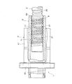
- FIG. 1 It is a side view of the ball screw spline of the present invention. It is a front view of the ball screw spline shown in FIG. It is side surface sectional drawing which notched a part of ball screw nut. It is a top view which shows the outer peripheral surface of a ball screw nut. It is a front view which shows the external appearance of a ball return member. It is a bottom view of a ball return member. It is the perspective view which notched a part of spline nut shown in FIG.
- FIG. 1 and 2 show an example of a ball screw spline to which the present invention is applied.
- FIG. 1 is a side view and
- FIG. 2 is a front view.
- the ball screw spline 1 is formed in a substantially cylindrical shape with a screw shaft 2, and is formed in a substantially cylindrical shape with a ball screw nut 3 screwed onto the screw shaft 2 via a large number of balls 5.
- the spline nut 4 is assembled to the outside of the ball screw nut 3 through a large number of balls 6.
- the screw shaft 2 has a ball rolling groove 20, and the ball rolling groove 20 is formed in a spiral shape with a predetermined lead along the outer peripheral surface of the screw shaft 2.
- the lead is a distance that the ball rolling groove 20 advances in the axial direction of the screw shaft 2 when the screw shaft 2 makes one rotation.
- a crest portion 21 is formed between the ball rolling grooves 20 of the screw shaft 2.
- FIG. 3 and 4 show a ball screw nut
- FIG. 3 is a side sectional view with a part cut away
- FIG. 4 is a plan view showing an outer peripheral surface.
- the ball screw nut 3 is composed of a screw portion 31 and an extension portion 32 which are integrally formed with the same outer diameter, and both the screw portion 31 and the extension portion 32 are through holes through which the screw shaft 2 passes. have.
- a load rolling groove 33 facing the ball rolling groove 20 of the screw shaft 2 is spirally formed on the inner peripheral surface of the threaded portion 31.
- the load rolling groove 33 and the ball rolling groove 20 of the screw shaft 2 face each other, so that a spiral load passage is formed in which the ball 5 rolls around the screw shaft 2 while applying a load. It will be.
- the threaded portion 31 of the ball screw nut 3 is provided with an elongated insertion hole 34 into which a ball return member 7 described later is mounted.
- the insertion holes 34 are arranged at equal intervals every 120 degrees with respect to the circumferential direction of the ball screw nut 3.
- Two insertion holes 34 are provided in series along the direction. That is, six insertion holes 34 are provided on the outer peripheral surface of the threaded portion 31 of the ball screw nut 3.
- step portions 34 a and 34 a for locking the ball return member 7 are formed on both edges in the longitudinal direction of the insertion hole 34.
- FIG. 3 is a cross-sectional view, only four insertion holes 34 are drawn for the ball screw nut 3. However, the other two insertion holes 34 are located on the front side in FIG. Not drawn.
- FIG. 5 and 6 show the ball return member 7
- FIG. 5 is a front view showing the appearance thereof
- FIG. 6 is a bottom view thereof.
- the ball return member 7 has an outer shape matched to the insertion hole 34, and includes a ball return portion 7a having a ball return passage 71 formed in an S shape, and step portions 34a, 34a of the insertion hole 34. And a fitting portion 7b having convex portions 72, 72 corresponding to the.
- the fitting portion 7b is formed so as to be completely accommodated without protruding to the outer peripheral surface of the ball screw nut 3 when the ball return member 7 is mounted in the insertion hole 34 of the ball screw nut 3. (See FIG. 2).
- the ball return passage 71 of the ball return portion 7 a is formed in an S shape, and changes the traveling direction of the ball 5 that has rolled on the ball rolling groove 20 of the screw shaft 2 toward the ball return member 7.
- the screw shaft 2 is moved over the peak portion 21 and returned to the ball rolling groove 20 one lead before.
- the ball return member 7 is installed in the insertion hole 34 of the ball screw nut 3, it is shown in FIG. 1 by the ball return passage 71 of the ball return member 7 and the load passage formed around the screw shaft 2.
- Such an infinite circulation path of the ball 5 for one turn around the screw shaft 2 is completed.
- the ball 5 circulates inside the infinite circulation path, and the ball screw nut 3 moves in the axial direction of the screw shaft 2. Will move.
- ball rolling grooves 35 for the spline nut 4 are provided on the outer peripheral surface of the ball screw nut 3 along the axial direction so as to avoid the insertion hole 34 (see FIG. 4). These ball rolling grooves 35 are arranged in 120-degree increments in the circumferential direction of the ball screw nut 3 as a set of two strips. In other words, in the ball screw nut 3, the insertion hole 34 of the ball return member 7 and the ball rolling groove 35 for the spline nut 4 are alternately arranged in the circumferential direction (see FIG. 2). ).
- the ball rolling groove 35 for the spline nut 4 is formed over the threaded portion 31 and the extending portion 32 of the ball screw nut 3, that is, over the entire length of the ball screw nut 3.
- FIG. 7 is a perspective view in which a part of the spline nut 4 shown in FIG. 1 is cut away.
- the spline nut 4 includes a nut body 41 and a flange portion 42 for fixing the spline nut 4 to a mechanical device. Both the nut body 41 and the flange portion 42 have through holes through which the ball screw nut 3 passes.
- the flange portion 42 is formed with a bolt hole that is used when the spline nut 4 is fixed.
- the nut body 41 of the spline nut 4 has an infinite circulation path 43 through which the ball 6 circulates infinitely on the inner peripheral surface of the through hole facing the ball screw nut 3.
- the infinite circulation path 43 includes a load straight groove formed on the outer peripheral surface of the ball screw nut 3 and facing the ball rolling groove 35 for the spline nut 4 and a no-load straight line formed in parallel with the load straight groove.
- a groove and a ball deflection groove that changes the rolling direction of the ball 6 180 degrees between the loaded linear groove and the unloaded linear groove and moves the ball 6 back and forth between these grooves.
- the endless circulation path 43 is open to the ball screw nut 3 in the entire area, and the balls 6 arranged in the endless circulation path 43 circulate in the endless circulation path 43 in a state of facing the ball screw nut 3. .
- a preload is applied to the ball 6 that rolls in the endless circulation path 43 while applying a load, and a backlash between the ball screw nut 3 and the spline nut 4 is eliminated.
- the ball screw nut 3 can be moved back and forth smoothly and accurately in the axial direction.
- the ball rolling groove 35 for the spline nut 4 shown in FIG. 2 is formed to be a pair of two, it rolls between the spline nut 4 and the ball screw nut 3. It is sufficient that a preload is applied to the ball 6 to be formed, and the ball rolling groove 35 for the spline nut 4 is not formed to be a pair, and the ball rolling for the single spline nut 4 is performed. It can also be formed as a groove 35.
- the ball screw spline 1 of the present invention configured as described above is used for, for example, an electric actuator capable of obtaining a desired stroke amount by driving an electric motor.
- an electric motor is connected to the other end of the screw shaft 2 to provide rotational driving to the screw shaft 2, while the spline nut 4 is fixed to the housing of the electric actuator with a bolt or the like.
- the ball screw nut 3 is prevented from rotating in the circumferential direction by the spline nut 4 so that the ball screw nut 3 moves in accordance with the amount of rotation of the screw shaft 2. Become. Thereby, a desired stroke amount can be given to the electric actuator.
- the ball screw spline 1 of the present invention since the ball return member 7 is mounted in the insertion hole 34 without protruding from the outer peripheral surface of the ball screw nut 3, like the conventional ball screw spline, The movement of the spline nut 4 is not hindered by the ball return member 7 of the screw portion 31, and the spline nut 4 can move over the entire length of the ball screw nut 3. That is, the stroke amount of the spline nut 4 corresponding to the entire length of the ball screw nut 3 can be secured. Accordingly, the electric actuator using the ball screw spline of the present invention can be miniaturized.
- a rotation driving means is provided to the spline nut 4 to provide rotation driving without applying rotation driving to the screw shaft 2. It is also possible to give a spiral motion to the ball screw nut.
Landscapes
- Engineering & Computer Science (AREA)
- General Engineering & Computer Science (AREA)
- Mechanical Engineering (AREA)
- Transmission Devices (AREA)
Priority Applications (3)
| Application Number | Priority Date | Filing Date | Title |
|---|---|---|---|
| DE112010001462.0T DE112010001462B4 (de) | 2009-03-31 | 2010-02-24 | Kugelgewinde-Keilwellentrieb |
| CN201080010079.6A CN102341620B (zh) | 2009-03-31 | 2010-02-24 | 滚珠丝杠花键轴 |
| US13/254,102 US8418573B2 (en) | 2009-03-31 | 2010-02-24 | Ball-screw spline |
Applications Claiming Priority (2)
| Application Number | Priority Date | Filing Date | Title |
|---|---|---|---|
| JP2009084640A JP4633846B2 (ja) | 2009-03-31 | 2009-03-31 | ボールねじスプライン |
| JP2009-084640 | 2009-03-31 |
Publications (1)
| Publication Number | Publication Date |
|---|---|
| WO2010113572A1 true WO2010113572A1 (ja) | 2010-10-07 |
Family
ID=42827874
Family Applications (1)
| Application Number | Title | Priority Date | Filing Date |
|---|---|---|---|
| PCT/JP2010/052832 WO2010113572A1 (ja) | 2009-03-31 | 2010-02-24 | ボールねじスプライン |
Country Status (6)
| Country | Link |
|---|---|
| US (1) | US8418573B2 (zh) |
| JP (1) | JP4633846B2 (zh) |
| CN (1) | CN102341620B (zh) |
| DE (1) | DE112010001462B4 (zh) |
| TW (1) | TWI495810B (zh) |
| WO (1) | WO2010113572A1 (zh) |
Families Citing this family (10)
| Publication number | Priority date | Publication date | Assignee | Title |
|---|---|---|---|---|
| DE102008000638B4 (de) * | 2008-03-13 | 2022-05-25 | Zf Friedrichshafen Ag | Betätigungseinrichtung zum Betätigen zumindest einer Schalteinrichtung und Verfahren zum Montieren und Demontieren derselben |
| KR20140040866A (ko) * | 2011-10-26 | 2014-04-03 | 닛본 세이고 가부시끼가이샤 | 볼 나사 장치 |
| ITRM20120587A1 (it) * | 2012-11-22 | 2014-05-23 | Umbra Cuscinetti Spa | Attuatore elettromeccanico lineare con antirotazione integrata. |
| CN104052188A (zh) * | 2014-07-02 | 2014-09-17 | 上海翱锐控制系统有限公司 | 精密电动缸 |
| DE102015209643B3 (de) * | 2015-05-27 | 2016-11-10 | Schaeffler Technologies AG & Co. KG | Kugelgewindetrieb |
| JP6980349B2 (ja) * | 2018-01-22 | 2021-12-15 | Thk株式会社 | ボールねじ装置 |
| CN110273994B (zh) * | 2019-06-20 | 2024-06-07 | 深圳市世椿智能装备股份有限公司 | 一种内花键滚珠丝杠副 |
| DE102021116144A1 (de) | 2021-06-22 | 2022-12-22 | Heidrive GmbH | Linearantrieb |
| JP7481374B2 (ja) | 2022-01-19 | 2024-05-10 | 株式会社日進製作所 | ホーニング加工装置 |
| CN116816889B (zh) * | 2023-08-30 | 2023-11-03 | 成都博森数智科技有限公司 | 一种往复运动结构及包含该往复运动结构的按摩装置 |
Citations (4)
| Publication number | Priority date | Publication date | Assignee | Title |
|---|---|---|---|---|
| JPH0343156U (zh) * | 1989-09-05 | 1991-04-23 | ||
| JP2000158144A (ja) * | 1998-11-30 | 2000-06-13 | Thk Co Ltd | 電動シリンダ及びこれを用いた溶接ガンユニット並びに溶接ロボット |
| JP2002515573A (ja) * | 1998-05-18 | 2002-05-28 | エスケイエフ エンジニアリング アンド リサーチ センター ビーブイ | ねじアクチュエータ、および該アクチュエータを含むブレーキキャリパ |
| JP2005014087A (ja) * | 2003-06-06 | 2005-01-20 | Honda Motor Co Ltd | 電動式スポット溶接ガン及びロッド進退機構 |
Family Cites Families (12)
| Publication number | Priority date | Publication date | Assignee | Title |
|---|---|---|---|---|
| US2874579A (en) * | 1956-02-21 | 1959-02-24 | Gen Motors Corp | High temperature hydraulic actuator |
| US3404581A (en) * | 1967-04-18 | 1968-10-08 | Sargent Industries | Ball screw actuator |
| US3989223A (en) * | 1973-12-28 | 1976-11-02 | Exxon Production Research Company | Rotary motion failsafe gate valve actuator |
| WO1983002141A1 (en) * | 1981-12-18 | 1983-06-23 | Hans Fickler | Linear drive device with two motors |
| JPH0761587B2 (ja) * | 1990-10-25 | 1995-07-05 | テイエチケー株式会社 | ボールねじガイドユニットを用いた移送テーブル |
| JP4275765B2 (ja) | 1998-04-15 | 2009-06-10 | Thk株式会社 | 電動シリンダ装置およびその製造方法 |
| US6464034B1 (en) * | 1999-02-04 | 2002-10-15 | Ntn Corporation | Electrically powered steering device |
| DE19944875A1 (de) | 1999-09-18 | 2001-03-22 | Schaeffler Waelzlager Ohg | Kugelgewindetrieb |
| JP4053826B2 (ja) * | 2002-06-25 | 2008-02-27 | Thk株式会社 | 循環部品、並びにこの循環部品を用いた運動案内装置及びボールねじ |
| TWI324230B (en) * | 2007-09-06 | 2010-05-01 | Hiwin Tech Corp | A nut rotation type ball screw |
| JP2009168093A (ja) * | 2008-01-15 | 2009-07-30 | Jtekt Corp | ボールねじ装置 |
| US20110138949A1 (en) * | 2009-12-14 | 2011-06-16 | Hamilton Sundstrand Corporation | Linear Actuator with Ball Bearing Spline |
-
2009
- 2009-03-31 JP JP2009084640A patent/JP4633846B2/ja active Active
-
2010
- 2010-02-24 DE DE112010001462.0T patent/DE112010001462B4/de active Active
- 2010-02-24 CN CN201080010079.6A patent/CN102341620B/zh active Active
- 2010-02-24 US US13/254,102 patent/US8418573B2/en active Active
- 2010-02-24 WO PCT/JP2010/052832 patent/WO2010113572A1/ja active Application Filing
- 2010-03-22 TW TW099108371A patent/TWI495810B/zh active
Patent Citations (4)
| Publication number | Priority date | Publication date | Assignee | Title |
|---|---|---|---|---|
| JPH0343156U (zh) * | 1989-09-05 | 1991-04-23 | ||
| JP2002515573A (ja) * | 1998-05-18 | 2002-05-28 | エスケイエフ エンジニアリング アンド リサーチ センター ビーブイ | ねじアクチュエータ、および該アクチュエータを含むブレーキキャリパ |
| JP2000158144A (ja) * | 1998-11-30 | 2000-06-13 | Thk Co Ltd | 電動シリンダ及びこれを用いた溶接ガンユニット並びに溶接ロボット |
| JP2005014087A (ja) * | 2003-06-06 | 2005-01-20 | Honda Motor Co Ltd | 電動式スポット溶接ガン及びロッド進退機構 |
Also Published As
| Publication number | Publication date |
|---|---|
| TW201100672A (en) | 2011-01-01 |
| DE112010001462B4 (de) | 2023-10-12 |
| JP2010236602A (ja) | 2010-10-21 |
| CN102341620B (zh) | 2014-08-20 |
| US20120024093A1 (en) | 2012-02-02 |
| US8418573B2 (en) | 2013-04-16 |
| TWI495810B (zh) | 2015-08-11 |
| JP4633846B2 (ja) | 2011-02-16 |
| DE112010001462T5 (de) | 2012-05-16 |
| CN102341620A (zh) | 2012-02-01 |
Similar Documents
| Publication | Publication Date | Title |
|---|---|---|
| WO2010113572A1 (ja) | ボールねじスプライン | |
| US8584546B2 (en) | Ball screw mechanism | |
| US20180334187A1 (en) | Steering system | |
| US5094118A (en) | Splined ball screw assembly having a nested structure | |
| US20150060187A1 (en) | Steering apparatus | |
| TWI651477B (zh) | 運動導引裝置 | |
| JP2010236602A5 (zh) | ||
| JP2009156415A (ja) | 電動リニアアクチュエータ | |
| WO2003029690A1 (fr) | Dispositif de vis a billes | |
| JP2015132308A (ja) | デフレクタ、ボールねじ装置、ボールねじ装置の製造方法、及びステアリング装置 | |
| US20100307271A1 (en) | Double teeth ball screw apparatus | |
| WO2007114036A1 (ja) | ボールねじ装置 | |
| JP2004108455A (ja) | ボールねじ装置 | |
| JP2012072867A (ja) | サスペンション装置及びこのサスペンション装置を組み込んだ車両 | |
| JP2007315512A (ja) | 電動リニアアクチュエータ | |
| KR100703243B1 (ko) | 볼 나사장치 | |
| JP2014092223A (ja) | ボールねじ装置及びボールねじ装置を備えた直動アクチュエータ | |
| EP1596101A2 (en) | Mechanism for converting rotary motion into linear motion | |
| EP2514997B1 (en) | Ball screw assembly | |
| JP2017075699A (ja) | トルク伝達可能なリニアブッシュ | |
| JP2006234151A (ja) | ボールねじ装置とリニアアクチュエータ | |
| US11480236B2 (en) | Ball screw device | |
| JP5270393B2 (ja) | 電動式動力舵取装置 | |
| JP5420922B2 (ja) | 電動式動力舵取装置 | |
| JP6491832B2 (ja) | 有限減速機 |
Legal Events
| Date | Code | Title | Description |
|---|---|---|---|
| WWE | Wipo information: entry into national phase |
Ref document number: 201080010079.6 Country of ref document: CN |
|
| 121 | Ep: the epo has been informed by wipo that ep was designated in this application |
Ref document number: 10758349 Country of ref document: EP Kind code of ref document: A1 |
|
| WWE | Wipo information: entry into national phase |
Ref document number: 13254102 Country of ref document: US |
|
| WWE | Wipo information: entry into national phase |
Ref document number: 112010001462 Country of ref document: DE Ref document number: 1120100014620 Country of ref document: DE |
|
| 122 | Ep: pct application non-entry in european phase |
Ref document number: 10758349 Country of ref document: EP Kind code of ref document: A1 |