WO2010110381A1 - 無線列車制御システム,無線列車制御車上システムおよび無線列車制御地上システム - Google Patents
無線列車制御システム,無線列車制御車上システムおよび無線列車制御地上システム Download PDFInfo
- Publication number
- WO2010110381A1 WO2010110381A1 PCT/JP2010/055261 JP2010055261W WO2010110381A1 WO 2010110381 A1 WO2010110381 A1 WO 2010110381A1 JP 2010055261 W JP2010055261 W JP 2010055261W WO 2010110381 A1 WO2010110381 A1 WO 2010110381A1
- Authority
- WO
- WIPO (PCT)
- Prior art keywords
- train
- train control
- wireless
- ground
- control
- Prior art date
- Legal status (The legal status is an assumption and is not a legal conclusion. Google has not performed a legal analysis and makes no representation as to the accuracy of the status listed.)
- Ceased
Links
Images



Classifications
-
- B—PERFORMING OPERATIONS; TRANSPORTING
- B60—VEHICLES IN GENERAL
- B60L—PROPULSION OF ELECTRICALLY-PROPELLED VEHICLES; SUPPLYING ELECTRIC POWER FOR AUXILIARY EQUIPMENT OF ELECTRICALLY-PROPELLED VEHICLES; ELECTRODYNAMIC BRAKE SYSTEMS FOR VEHICLES IN GENERAL; MAGNETIC SUSPENSION OR LEVITATION FOR VEHICLES; MONITORING OPERATING VARIABLES OF ELECTRICALLY-PROPELLED VEHICLES; ELECTRIC SAFETY DEVICES FOR ELECTRICALLY-PROPELLED VEHICLES
- B60L15/00—Methods, circuits, or devices for controlling the traction-motor speed of electrically-propelled vehicles
- B60L15/40—Adaptation of control equipment on vehicle for remote actuation from a stationary place
-
- B—PERFORMING OPERATIONS; TRANSPORTING
- B61—RAILWAYS
- B61L—GUIDING RAILWAY TRAFFIC; ENSURING THE SAFETY OF RAILWAY TRAFFIC
- B61L15/00—Indicators provided on the vehicle or train for signalling purposes
- B61L15/0018—Communication with or on the vehicle or train
- B61L15/0027—Radio-based, e.g. using GSM-R
-
- B—PERFORMING OPERATIONS; TRANSPORTING
- B61—RAILWAYS
- B61L—GUIDING RAILWAY TRAFFIC; ENSURING THE SAFETY OF RAILWAY TRAFFIC
- B61L23/00—Control, warning or like safety means along the route or between vehicles or trains
- B61L23/08—Control, warning or like safety means along the route or between vehicles or trains for controlling traffic in one direction only
- B61L23/14—Control, warning or like safety means along the route or between vehicles or trains for controlling traffic in one direction only automatically operated
-
- B—PERFORMING OPERATIONS; TRANSPORTING
- B61—RAILWAYS
- B61L—GUIDING RAILWAY TRAFFIC; ENSURING THE SAFETY OF RAILWAY TRAFFIC
- B61L27/00—Central railway traffic control systems; Trackside control; Communication systems specially adapted therefor
- B61L27/20—Trackside control of safe travel of vehicle or train, e.g. braking curve calculation
-
- B—PERFORMING OPERATIONS; TRANSPORTING
- B60—VEHICLES IN GENERAL
- B60L—PROPULSION OF ELECTRICALLY-PROPELLED VEHICLES; SUPPLYING ELECTRIC POWER FOR AUXILIARY EQUIPMENT OF ELECTRICALLY-PROPELLED VEHICLES; ELECTRODYNAMIC BRAKE SYSTEMS FOR VEHICLES IN GENERAL; MAGNETIC SUSPENSION OR LEVITATION FOR VEHICLES; MONITORING OPERATING VARIABLES OF ELECTRICALLY-PROPELLED VEHICLES; ELECTRIC SAFETY DEVICES FOR ELECTRICALLY-PROPELLED VEHICLES
- B60L2200/00—Type of vehicles
- B60L2200/26—Rail vehicles
-
- Y—GENERAL TAGGING OF NEW TECHNOLOGICAL DEVELOPMENTS; GENERAL TAGGING OF CROSS-SECTIONAL TECHNOLOGIES SPANNING OVER SEVERAL SECTIONS OF THE IPC; TECHNICAL SUBJECTS COVERED BY FORMER USPC CROSS-REFERENCE ART COLLECTIONS [XRACs] AND DIGESTS
- Y02—TECHNOLOGIES OR APPLICATIONS FOR MITIGATION OR ADAPTATION AGAINST CLIMATE CHANGE
- Y02T—CLIMATE CHANGE MITIGATION TECHNOLOGIES RELATED TO TRANSPORTATION
- Y02T90/00—Enabling technologies or technologies with a potential or indirect contribution to GHG emissions mitigation
- Y02T90/10—Technologies relating to charging of electric vehicles
- Y02T90/16—Information or communication technologies improving the operation of electric vehicles
Definitions
- the control of a moving body that moves on a predetermined route is performed wirelessly, and in particular, relates to a wireless train control system.
- Patent Document 1 In recent years, even in the wireless train control system (Patent Document 1) devised for ground equipment reduction, train detection cannot be controlled until communication is established because train detection is self-reported from the train. The safety of the train was still dependent on the driver.
- Train control is performed by the system within the control range of the safety system, and trains are automatically prevented from approaching each other.
- prevention of approach between trains depends on human attention.
- it is necessary to safely and reliably enter the train from outside the control range of the security system.
- a radio signal control system using spatial waves when multiple trains enter the system's control range, if the subsequent train is recognized by the system first, there is a possibility of collision without recognizing the preceding train. is there.
- An object of the present invention is to provide a wireless train control system that prevents a train that cannot be controlled by the wireless train control system from entering the wireless train control section from outside the wireless train control section.
- the present invention comprises a ground element installed in a section on a route not performing wireless train control, and the train includes a ground element detection device that detects the ground element, After detecting the ground unit, the mobile station that starts wireless communication with the base station and the section where the train does not receive train control information and enters the control section for wireless train control from the section where wireless train control is not performed A train control device for stopping the train before the train enters the control section of the wireless train control.
- a mobile station that is mounted on a train traveling on a predetermined route and that receives train control information wirelessly from a ground control device, and a ground unit installed in a section on a route that is not performing wireless train control are detected.
- a train control device that starts wireless communication with the ground control device via a mobile station when the ground control device detects a ground control, and a section on a route that does not perform wireless train control
- the train control device stops the train in the section on the route not performing the wireless train control.
- the 1st ground element which is installed in the section on the path which is not performing wireless train control, and transmits the information which becomes a trigger for a mobile station to start wireless communication to the train side, and the path which is not performing wireless train control If the train control information is not transmitted from the base station to the mobile station before the train enters the control section for wireless train control from the upper section, the train is placed in the section on the route where wireless train control is not performed.
- a second ground element that transmits information serving as a brake trigger for stopping to the train side.
- the safety of the wireless train control system is improved. Can be planned.
- FIG. 1 is a diagram showing an embodiment of a method for entering a radio signal control section of a radio train control system according to the present invention.
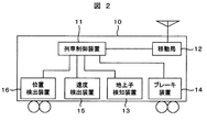
- FIG. 2 is a diagram illustrating a configuration example of a train of the wireless train control system according to the present invention.
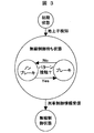
- FIG. 3 is a diagram showing transition conditions for the approach processing of the radio train control system according to the present invention.
- FIG. 4 is a diagram showing a flowchart of the approach processing of the radio train control system according to the present invention.
- FIG. 5 is a diagram illustrating step 108 of the flowchart.
- FIG. 6 is a diagram showing another embodiment of a method for entering a radio signal control section of the radio train control system according to the present invention.
- FIG. 1 is an embodiment of the present invention, and is a diagram showing a configuration of an approach method from a section where wireless train control is not performed to a wireless train control section.
- the train 10 traveling on the specified track 50 communicates with the ground control device 40 by radio via the base station 30 on which the antenna is installed.
- On track 50 there are other sections that are not the control range of the radio train control system, and radio train control sections that are the control range of the radio train control system (sections where radio train control is possible), between which the system boundary Is provided.
- the other section described above is a section outside the control range of the radio train control system, and even a section without a security system such as a garage is a control section of a security system other than the radio train control system. Also good.
- the ground unit 20 is installed outside the radio train control system (other section side) from the system boundary.
- the ground element 20 notifies the train 10 of position information that allows calculation of the remaining distance from the installation position of the ground element 20 to the system boundary.
- the ground unit 20 is preferably constituted by a non-powered ground unit with low installation cost. However, the present invention can naturally be applied even to a grounded ground unit.
- the ground unit 20 notifies information on the remaining distance to the boundary itself (hereinafter, remaining distance information) as position information.
- remaining distance information information on the remaining distance to the boundary itself
- the mode switching section shown in FIG. 1 is a section in which the remaining distance information is received from the ground unit 20 and the train 10 starts wireless communication with the ground control device 40 via the base station 30.
- FIG. 2 is a diagram showing a configuration example of the train 10.
- the mobile station 12 that communicates wirelessly with the ground base station 30, the train control device 11, the ground child detection device 13 that receives the remaining distance information from the ground child 20, and the braking operation of the train 10.
- a brake device 14, a speed detection device 15, and a position detection device 16 are provided.
- the train control device 11 is connected to the mobile station 12, the ground detector 13, the brake device 14, the speed detector 15, and the position detector 16.
- the train control unit 11 When the train 10 traveling from the other section toward the wireless train control section detects the ground unit 20 by the ground unit detection device 13, the train control unit 11 receives the information, and the train control unit 11 is based on the mobile station 12. Communication with the station 30 is started. Thereafter, the mobile station 12 waits to receive train control information from the ground control device 40.
- the train control information is stop limit information in the radio train control section (information on a position where the own train can travel safely without colliding with other trains or without derailing).
- the ground element detection device 13 transmits the remaining distance information from the ground element 20 to the system boundary to the train control device, and the train control device 11 creates a brake pattern for stopping before the system boundary from the remaining distance information. (Refer to the brake pattern shown in FIG. 1).
- the installation position of the ground element 20 is between the train tail when the train stops before the system boundary due to the brake pattern and the system boundary.
- the brake may be applied immediately after creating the brake pattern. Therefore, the speed of the train when detecting the ground element 20 is set to a speed at which the brake can be applied after the ground element 20 is detected and the vehicle can stop before the system boundary.
- the train control device 11 controls the brake device 14 to apply the brake according to the calculated brake pattern, and train 10 before the system boundary. Stop.
- the train control device 11 controls the brake device 14 to control the brake pattern whether the train is running or stopped. Release the brake by, run the train according to the train control information, enter the radio train control section across the system boundary.
- the case where the brake is applied according to the brake pattern means that the position and speed detected by the position detection device 16 (speed generator, etc.) and the speed detection device 15 mounted on the train 10 are in contact with the brake pattern. It is.
- FIG. 3 is a diagram showing the state transition of the entry process of the present invention.
- the train control device 11 of the present invention makes a transition from an initial state to a state waiting for wireless control (waiting for reception of train control information) on condition that a ground element is detected.
- a brake state or a non-brake (not braked) state is determined depending on whether or not the traveling speed of the train contacts the brake pattern created by the train control device 11.
- the wireless control state transitions from the wireless control waiting state.
- FIG. 4 is a view showing a flowchart of the approach processing of the present invention.
- Steps 101 and 102 The train traveling toward the system boundary repeats the determination of whether or not a ground element has been detected (initial state). If a ground element is detected, the initial state is exited to step 103. If not detected, the process returns to step 101 and continues running.
- Step 103 When the ground element detecting device detects the ground element, the initial state is exited, and the on-board wireless device (mobile station 12) is turned on. As a result, communication between the mobile station 12 installed in the train 10 and the base station 30 on the ground is started.
- the on-board wireless device mobile station 12
- Step 104 The ground element detection device receives the remaining distance information from the ground element to the system boundary.
- Step 105 A brake pattern that stops before the system boundary is calculated from the remaining distance information received by the train control device in Step 104.
- Steps 106 to 108 Processing for waiting for wireless control. Details will be described later.
- Step 106 The train transmits its own train position from the onboard radio (mobile station 12) to the ground control device while updating its own train position with a position detection device such as a speed generator.
- a position detection device such as a speed generator.
- the ground control device can recognize the approaching train, creates train control information for the approaching train, and transmits the train control information to the train 10 via the base station 30.
- Step 107 The train waits to receive train control information from the ground control device, and determines whether the mobile station 12 has received the train control information. If received by the mobile station 12, the wireless control wait state is exited and the process proceeds to step 109. If the mobile station 12 has not received the signal, the process proceeds to step 108 and the wireless control wait state is continued.
- Step 108 It is determined whether the brake state or the non-brake state. The processing in this block is shown in FIG. If the train control information is not received by the mobile station 12, the state determination process is entered. In step 110, it is determined whether the train speed contacts the brake pattern calculated in step 105. If the brake pattern is touched, the brake state is entered. If there is no contact, it will transition to the non-brake state. After executing the state determination, the process returns to step 106 and the loop of 106 to 108 is repeated.
- Step 109 Since the train travels according to the received train control information, the train control based on the brake pattern calculated in Step 105 is canceled and the wireless control state is entered.
- a brake pattern is created from the remaining distance information received from the ground element 20, the train is run within a range not exceeding the brake pattern, and the train control information is waited for. That is, if the train control information can be received before the train reaches the system boundary, it is possible to safely enter the wireless train control system across the system boundary without stopping. Therefore, it is possible to operate an energy-saving train as compared with a method of always stopping before entering the system boundary and waiting to receive train control information.
- Example 1 The main difference from Example 1 is that the ground unit is installed in two places.
- FIG. 6 is a diagram showing a configuration of an approach method to a wireless train control section from a section not performing the wireless train control according to the present embodiment.
- the train 10 traveling on the predetermined track 50 communicates with the ground control device 40 via the base station 30 by radio.
- On the track 50 there are other sections that are not the control range of the radio train control system and radio train control sections that are the control range of the radio train control system (sections where radio train control is possible), and a system boundary is provided between them.
- the other section described above is a section outside the control range of the radio train control system, and even a section without a security system such as a garage is a control section of a security system other than the radio train control system. Also good.
- the ground element 21a is installed outside the radio train control system from the system boundary (the other section side), and the ground element 21b is installed between the system boundary and the ground element 21a. If these ground elements 21a and 21b are constituted by non-powered ground elements, the installation cost is low and desirable. However, the present invention can naturally be applied even if they are powered ground elements.
- the installation position of the ground element 21b is a position where the train can brake after detecting the ground element 21b and stop before the system boundary.
- the installation position of the ground element 21a is between the tail of the train and the system boundary when the train stops before the system boundary by the brake.
- the configuration of the train 10 is the same as in FIG.
- the on-board wireless device (mobile station 12) starts communication with the base station 30, and the ground control is performed. Wait for reception of train control information from the device 40.
- the ground element detection device 13 of the train 10 receives the position information of the ground element 21a from the ground element 21a.
- the information received from the ground unit 21a is not necessarily position information, and may be information that serves as a trigger for the train 10 to start wireless communication with the ground control device.
- the ground element detection device 13 of the train 10 When the ground element detection device 13 of the train 10 detects the ground element 21b, it receives a stop command from the ground element 21b.
- the speed of the train when detecting the ground element 21b is set to a speed at which the brake is applied after the detection and the vehicle can stop before the system boundary.
- the train control device 11 runs the train according to the train control information and crosses the system boundary to the wireless train. Enter the control zone. If the train control information is not received from the ground control device 40 until the ground child 21b is detected, the train control device 11 applies the brake from the point where the ground child 21b is detected, and stops the train before the system boundary. .
- the brake is released from the time when the train control information is received, the vehicle travels according to the train control information, and goes to the radio train control section across the system boundary. enter in.
- the ground element 21b detects a brake for stopping a train in a state that cannot be controlled by the wireless train control system (a train that has not received train control information from the ground control device) before the system boundary. Since it starts with information, there is no need to generate a brake pattern in the train control device 11, and there is an effect that the train control device can be simplified.
Landscapes
- Engineering & Computer Science (AREA)
- Mechanical Engineering (AREA)
- Power Engineering (AREA)
- Transportation (AREA)
- Electric Propulsion And Braking For Vehicles (AREA)
- Train Traffic Observation, Control, And Security (AREA)
Abstract
Description
11 列車制御装置
12 移動局
13 地上子検知装置
14 ブレーキ装置
15 速度検出装置
16 位置検出装置
20,21a,21b 地上子
30 基地局
40 地上制御装置
50 軌道
Claims (12)
- 所定の経路上を走行し、無線通信可能な移動局を備える列車と、
前記経路の沿線に設置され、前記移動局と無線通信可能な基地局と、
前記基地局を介して前記移動局へ列車制御情報を送信する地上制御装置と、を備える無線列車制御システムにおいて、
前記無線列車制御を行っていない前記経路上の区間に設置される地上子と、を備え、
前記列車は、
前記地上子を検知する地上子検知装置と、
前記地上子検知装置が前記地上子を検知した後に、前記基地局と無線通信を開始する前記移動局と、
前記列車が列車制御情報を受信しない状態で、前記無線列車制御を行っていない区間から前記無線列車制御の制御区間へ進入する場合に、前記無線列車制御の制御区間へ前記列車が進入する前に前記列車を停止させる列車制御装置と、を備えることを特徴とする無線列車制御システム。 - 請求項1記載の無線列車制御システムにおいて、
前記列車は、前記列車の位置を検出する位置検出装置と、前記列車の速度を検出する速度検出装置と、を備え、
前記地上子は、該地上子の設置位置から前記無線列車制御を行っていない区間と前記無線列車制御の制御区間とのシステム境界までの残距離を算出可能な位置情報を有し、
前記地上子検知装置は、前記地上子から前記位置情報を受信する手段を有し、
前記列車制御装置は、地上子検知装置から前記位置情報を受信して、前記無線列車制御を行っていない区間内に列車を停止させるブレーキパターンを作成し、前記列車の位置と前記列車の前記速度と前記ブレーキパターンとに基づいて前記列車を停止させることを特徴とする無線列車制御システム。 - 請求項2記載の無線列車制御システムにおいて、
前記地上子は、前記ブレーキパターンに従って停止した列車の後尾から前記システム境界までの間に設置されることを特徴とする無線列車制御システム。 - 請求項3記載の無線列車制御システムにおいて、
前記地上子上を通過する際の前記列車の速度は、前記地上子を検知後に前記ブレーキパターンに従って停止可能な速度とすることを特徴とする無線列車制御システム。 - 請求項1に記載の無線列車制御システムにおいて、
前記移動局が前記列車制御情報を受信すると、前記ブレーキパターンに基づくブレーキを解除して、前記列車制御情報に基づいて列車を制御する無線列車制御システム。 - 請求項1記載の無線列車制御システムにおいて、
前記地上子は、第1地上子と、前記第1地上子と前記システム境界との間に設置される第2地上子とからなり、
前記移動局は、前記地上子検知装置が前記第1地上子を検知した場合に、前記基地局と無線通信を開始し、
前記列車制御装置は、前記地上子検知装置が前記第2地上子を検出した場合に、ブレーキを掛けて前記列車を停止させることを特徴とする無線列車制御システム。 - 請求項6に記載の無線列車制御システムにおいて、
前記移動局が前記列車制御情報を受信すると、前記ブレーキを解除して、前記列車制御情報に基づいて列車を制御する無線列車制御システム。 - 請求項7記載の無線列車制御システムにおいて、
前記第2地上子の設置位置は、前記地上子検知装置が前記第2地上子を検知した後にブレーキを掛けて、前記無線列車制御を行っていない区間と前記無線列車制御の制御区間とのシステム境界手前に列車が停止可能な位置とすることを特徴とする無線列車制御システム。 - 請求項1に記載の無線列車制御システムにおいて、
前記列車制御情報は停止限界情報とする無線列車制御システム。 - 所定の経路上を走行する列車に搭載され、地上制御装置から無線により列車制御情報を受信する移動局と、
前記無線列車制御を行っていない前記経路上の区間に設置される地上子を検知する地上子検知装置と、
前記地上子検知装置が前記地上子を検知した場合に、前記移動局を介して前記地上制御装置と無線通信を開始する列車制御装置と、
前記無線列車制御を行っていない前記経路上の区間から前記無線列車制御の制御区間へ前記列車が進入する前に前記移動局が前記列車制御情報を受信していない場合に、前記列車制御装置は、前記無線列車制御を行っていない前記経路上の区間内に前記列車を停止させることを特徴とする無線列車制御車上システム。 - 無線通信可能な移動局を備える列車の走行する経路沿線に設置され、前記移動局と無線通信可能な基地局と、
前記基地局を介して前記移動局へ列車制御情報を送信する地上制御装置と、を備える無線列車制御地上システムにおいて、
前記無線列車制御を行っていない前記経路上の区間に設置されて、前記移動局が無線通信を開始するトリガとなる情報を前記列車側へ送信する第1地上子と、
前記無線列車制御を行っていない前記経路上の区間から前記無線列車制御の制御区間へ前記列車が進入する前に、前記基地局から前記移動局へ前記列車制御情報を送信していない場合に、前記無線列車制御を行っていない前記経路上の区間内に前記列車を停止させるためのブレーキのトリガとなる情報を前記列車側へ送信する第2地上子と、を備えることを特徴とする無線列車制御地上システム。 - 所定の経路上を走行する列車と所定の経路沿線に設置された基地局間で無線通信を行う無線列車制御システムにおいて、
前記所定の経路上において、無線列車制御の制御区間と、無線列車制御を行っていない区間とがある場合、
前記無線列車制御を行っていない区間内に設置され、その設置位置から前記無線列車制御を行っていない区間と前記無線列車制御の制御区間との境界までの残距離を算出可能な位置情報を前記列車に通知する地上子を有し、
前記列車は、前記地上子から前記位置情報を受信する地上子検知装置と、前記地上子を検知した場合に基地局と通信を開始する移動局と、
を有する無線列車制御システム。
Priority Applications (3)
| Application Number | Priority Date | Filing Date | Title |
|---|---|---|---|
| CN201080008534.9A CN102325684B (zh) | 2009-03-27 | 2010-03-25 | 无线列车控制系统、无线列车控制车上系统及无线列车控制地上系统 |
| GB1113885.6A GB2480568B (en) | 2009-03-27 | 2010-03-25 | Wireless train control system, on-board wireless train control system and trackside wireless train control system |
| KR1020117019371A KR101247889B1 (ko) | 2009-03-27 | 2010-03-25 | 무선 열차 제어 시스템, 무선 열차 제어 차상 시스템 및 무선 열차 제어 지상 시스템 |
Applications Claiming Priority (2)
| Application Number | Priority Date | Filing Date | Title |
|---|---|---|---|
| JP2009078007A JP5268737B2 (ja) | 2009-03-27 | 2009-03-27 | 無線列車制御システム,無線列車制御車上システムおよび無線列車制御地上システム |
| JP2009-078007 | 2009-03-27 |
Publications (1)
| Publication Number | Publication Date |
|---|---|
| WO2010110381A1 true WO2010110381A1 (ja) | 2010-09-30 |
Family
ID=42781072
Family Applications (1)
| Application Number | Title | Priority Date | Filing Date |
|---|---|---|---|
| PCT/JP2010/055261 Ceased WO2010110381A1 (ja) | 2009-03-27 | 2010-03-25 | 無線列車制御システム,無線列車制御車上システムおよび無線列車制御地上システム |
Country Status (5)
| Country | Link |
|---|---|
| JP (1) | JP5268737B2 (ja) |
| KR (1) | KR101247889B1 (ja) |
| CN (1) | CN102325684B (ja) |
| GB (1) | GB2480568B (ja) |
| WO (1) | WO2010110381A1 (ja) |
Cited By (3)
| Publication number | Priority date | Publication date | Assignee | Title |
|---|---|---|---|---|
| CN103826910A (zh) * | 2011-09-30 | 2014-05-28 | 日本信号株式会社 | 列车控制系统 |
| CN109131442A (zh) * | 2018-08-06 | 2019-01-04 | 中国铁道科学研究院集团有限公司 | 高速综合检测列车的车载远程控制装置及信号检测系统 |
| CN117208026A (zh) * | 2023-09-07 | 2023-12-12 | 中铁武汉电气化局集团上海工程建设有限公司 | 一种车轨云协同的铁路信号智能检测轨行器系统 |
Families Citing this family (7)
| Publication number | Priority date | Publication date | Assignee | Title |
|---|---|---|---|---|
| JP5858711B2 (ja) * | 2011-09-30 | 2016-02-10 | 日本信号株式会社 | 列車制御システムの車上装置 |
| JP5859365B2 (ja) * | 2012-03-30 | 2016-02-10 | 日本信号株式会社 | 列車制御装置 |
| JP5856935B2 (ja) * | 2012-09-14 | 2016-02-10 | 株式会社日立製作所 | 列車制御システム |
| WO2014097349A1 (ja) * | 2012-12-19 | 2014-06-26 | 株式会社 東芝 | 列車制御装置および列車制御方法 |
| JP5885654B2 (ja) * | 2012-12-28 | 2016-03-15 | 株式会社東芝 | 列車制御システム |
| JP6791264B2 (ja) | 2016-12-13 | 2020-11-25 | 三菱電機株式会社 | 列車制御システム、地上制御装置および車上制御装置 |
| CN108082225A (zh) * | 2017-12-18 | 2018-05-29 | 江苏添仂智能科技有限公司 | 基于uwb传感器作为轨道信标对轨道无人车进站进行自动控制的方法 |
Citations (4)
| Publication number | Priority date | Publication date | Assignee | Title |
|---|---|---|---|---|
| JPH11245818A (ja) * | 1998-03-06 | 1999-09-14 | Toshiba Corp | 列車通信装置および方法 |
| JP2001010498A (ja) * | 1999-06-28 | 2001-01-16 | Nippon Signal Co Ltd:The | 車両制御装置、地上装置及び車上装置 |
| JP2005067258A (ja) * | 2003-08-27 | 2005-03-17 | Nippon Signal Co Ltd:The | 列車制御装置 |
| JP2006001349A (ja) * | 2004-06-16 | 2006-01-05 | Hitachi Ltd | 列車位置検知システム |
Family Cites Families (6)
| Publication number | Priority date | Publication date | Assignee | Title |
|---|---|---|---|---|
| JP3381126B2 (ja) * | 1995-08-07 | 2003-02-24 | オムロン株式会社 | 自動列車停止装置 |
| JP2000318611A (ja) | 1999-05-07 | 2000-11-21 | Railway Technical Res Inst | 自動列車停止装置 |
| JP2001213320A (ja) | 2000-01-31 | 2001-08-07 | Central Japan Railway Co | 列車制御装置 |
| JP2003261028A (ja) * | 2002-03-06 | 2003-09-16 | Toshiba Corp | 無線応用閉塞制御システム及び方法 |
| KR100402348B1 (en) | 2003-07-02 | 2003-10-22 | Bong Taek Kim | Automatic train protection stop device for controlling railroad using data communication |
| CN1794690A (zh) * | 2006-01-12 | 2006-06-28 | 北京交通大学 | 一种采用无线机车信号实现机车信号主体化的方法 |
-
2009
- 2009-03-27 JP JP2009078007A patent/JP5268737B2/ja not_active Expired - Fee Related
-
2010
- 2010-03-25 GB GB1113885.6A patent/GB2480568B/en active Active
- 2010-03-25 WO PCT/JP2010/055261 patent/WO2010110381A1/ja not_active Ceased
- 2010-03-25 KR KR1020117019371A patent/KR101247889B1/ko not_active Expired - Fee Related
- 2010-03-25 CN CN201080008534.9A patent/CN102325684B/zh active Active
Patent Citations (4)
| Publication number | Priority date | Publication date | Assignee | Title |
|---|---|---|---|---|
| JPH11245818A (ja) * | 1998-03-06 | 1999-09-14 | Toshiba Corp | 列車通信装置および方法 |
| JP2001010498A (ja) * | 1999-06-28 | 2001-01-16 | Nippon Signal Co Ltd:The | 車両制御装置、地上装置及び車上装置 |
| JP2005067258A (ja) * | 2003-08-27 | 2005-03-17 | Nippon Signal Co Ltd:The | 列車制御装置 |
| JP2006001349A (ja) * | 2004-06-16 | 2006-01-05 | Hitachi Ltd | 列車位置検知システム |
Cited By (5)
| Publication number | Priority date | Publication date | Assignee | Title |
|---|---|---|---|---|
| CN103826910A (zh) * | 2011-09-30 | 2014-05-28 | 日本信号株式会社 | 列车控制系统 |
| CN103826910B (zh) * | 2011-09-30 | 2016-10-26 | 日本信号株式会社 | 列车控制系统 |
| CN109131442A (zh) * | 2018-08-06 | 2019-01-04 | 中国铁道科学研究院集团有限公司 | 高速综合检测列车的车载远程控制装置及信号检测系统 |
| CN117208026A (zh) * | 2023-09-07 | 2023-12-12 | 中铁武汉电气化局集团上海工程建设有限公司 | 一种车轨云协同的铁路信号智能检测轨行器系统 |
| CN117208026B (zh) * | 2023-09-07 | 2024-05-03 | 中铁武汉电气化局集团上海工程建设有限公司 | 一种车轨云协同的铁路信号智能检测轨行器系统 |
Also Published As
| Publication number | Publication date |
|---|---|
| GB201113885D0 (en) | 2011-09-28 |
| JP5268737B2 (ja) | 2013-08-21 |
| GB2480568B (en) | 2013-10-09 |
| KR101247889B1 (ko) | 2013-03-26 |
| CN102325684B (zh) | 2014-12-03 |
| KR20110113750A (ko) | 2011-10-18 |
| GB2480568A (en) | 2011-11-23 |
| JP2010228574A (ja) | 2010-10-14 |
| CN102325684A (zh) | 2012-01-18 |
Similar Documents
| Publication | Publication Date | Title |
|---|---|---|
| JP5268737B2 (ja) | 無線列車制御システム,無線列車制御車上システムおよび無線列車制御地上システム | |
| US9663125B2 (en) | Train control system | |
| JP6296676B2 (ja) | 列車制御システム | |
| US9475509B2 (en) | Guided ground vehicle including a device for managing a derailment of the vehicle, and associated derailment management method | |
| US7099754B2 (en) | Signal safety method, signal safety apparatus and signal safety system | |
| JP2013075644A (ja) | 列車制御システム | |
| CN106394610A (zh) | 一种降级信号系统下的点式ato防护方法 | |
| JP7289184B2 (ja) | 自動列車運転システム | |
| US20180105190A1 (en) | Method and device for vehicles, which detect the collision of a further vehicle | |
| CN105579323B (zh) | 轨道车辆的运行 | |
| JP2009241685A (ja) | 無線列車制御システム | |
| KR101869587B1 (ko) | 열차 제어 시스템 | |
| JP6399752B2 (ja) | 車両位置認識装置 | |
| KR20160071645A (ko) | 열차의 분리-결합 시스템 | |
| JP2003011819A (ja) | 軌道車両自動制御システム | |
| JP3676148B2 (ja) | 列車の運転保安方法 | |
| KR101792931B1 (ko) | 트램 운행 시스템 및 방법 | |
| JP3607966B2 (ja) | 走行支援システム | |
| JP2001063578A (ja) | 閉そく装置 | |
| JP4125019B2 (ja) | 軌道車両の運行支援方法および同運行支援システム | |
| JP2010241281A (ja) | 列車制御装置及び列車制御システム | |
| KR101370413B1 (ko) | Atc 모드에서의 열차 과주 방지 시스템 및 방법 | |
| JP2003095104A (ja) | 列車運行管理方法および列車運行管理システム | |
| KR20060010620A (ko) | 무선 통신을 이용한 철도 차량의 건널목 정시간 제어시스템 | |
| KR20140003972A (ko) | Ats 모드에서의 열차 과주 방지 시스템 |
Legal Events
| Date | Code | Title | Description |
|---|---|---|---|
| WWE | Wipo information: entry into national phase |
Ref document number: 201080008534.9 Country of ref document: CN |
|
| 121 | Ep: the epo has been informed by wipo that ep was designated in this application |
Ref document number: 10756177 Country of ref document: EP Kind code of ref document: A1 |
|
| ENP | Entry into the national phase |
Ref document number: 1113885 Country of ref document: GB Kind code of ref document: A Free format text: PCT FILING DATE = 20100325 |
|
| WWE | Wipo information: entry into national phase |
Ref document number: 1113885.6 Country of ref document: GB |
|
| ENP | Entry into the national phase |
Ref document number: 20117019371 Country of ref document: KR Kind code of ref document: A |
|
| NENP | Non-entry into the national phase |
Ref country code: DE |
|
| 122 | Ep: pct application non-entry in european phase |
Ref document number: 10756177 Country of ref document: EP Kind code of ref document: A1 |