WO2010109975A1 - Dispositif de mesure de la forme - Google Patents
Dispositif de mesure de la forme Download PDFInfo
- Publication number
- WO2010109975A1 WO2010109975A1 PCT/JP2010/052162 JP2010052162W WO2010109975A1 WO 2010109975 A1 WO2010109975 A1 WO 2010109975A1 JP 2010052162 W JP2010052162 W JP 2010052162W WO 2010109975 A1 WO2010109975 A1 WO 2010109975A1
- Authority
- WO
- WIPO (PCT)
- Prior art keywords
- probe
- workpiece
- sphere
- stage
- support shaft
- Prior art date
Links
Images


Classifications
-
- G—PHYSICS
- G01—MEASURING; TESTING
- G01B—MEASURING LENGTH, THICKNESS OR SIMILAR LINEAR DIMENSIONS; MEASURING ANGLES; MEASURING AREAS; MEASURING IRREGULARITIES OF SURFACES OR CONTOURS
- G01B5/00—Measuring arrangements characterised by the use of mechanical techniques
- G01B5/004—Measuring arrangements characterised by the use of mechanical techniques for measuring coordinates of points
- G01B5/008—Measuring arrangements characterised by the use of mechanical techniques for measuring coordinates of points using coordinate measuring machines
- G01B5/012—Contact-making feeler heads therefor
-
- G—PHYSICS
- G01—MEASURING; TESTING
- G01B—MEASURING LENGTH, THICKNESS OR SIMILAR LINEAR DIMENSIONS; MEASURING ANGLES; MEASURING AREAS; MEASURING IRREGULARITIES OF SURFACES OR CONTOURS
- G01B5/00—Measuring arrangements characterised by the use of mechanical techniques
- G01B5/20—Measuring arrangements characterised by the use of mechanical techniques for measuring contours or curvatures
-
- G—PHYSICS
- G01—MEASURING; TESTING
- G01B—MEASURING LENGTH, THICKNESS OR SIMILAR LINEAR DIMENSIONS; MEASURING ANGLES; MEASURING AREAS; MEASURING IRREGULARITIES OF SURFACES OR CONTOURS
- G01B5/00—Measuring arrangements characterised by the use of mechanical techniques
- G01B5/004—Measuring arrangements characterised by the use of mechanical techniques for measuring coordinates of points
- G01B5/008—Measuring arrangements characterised by the use of mechanical techniques for measuring coordinates of points using coordinate measuring machines
- G01B5/012—Contact-making feeler heads therefor
- G01B5/016—Constructional details of contacts
Definitions
- the present invention relates to a shape measuring apparatus that measures the surface shape of a workpiece based on the amount of movement of the probe by bringing the probe into contact with or moving in contact with the workpiece surface.
- the tip shape of the probe for example, shapes as shown in FIGS. 10A to 10D are known.
- the basic tip shape of the probe is as shown in FIG. 10 (a) and FIG. 10 (b) which can suppress errors caused by the tip shape as much as possible. It is spherical.
- the shape as shown in FIG. 10A is easy to manufacture with high accuracy, and is the mainstream shape with the highest accuracy in the contact type measurement method of the order of sub-micro.
- the probe as described above is brought into contact with the workpiece, and the point contact position with the workpiece is extracted by calculation data offset by a known probe shape from the center coordinates of the probe held by the measuring instrument.
- a method for capturing a shape is known. If the tip is a sphere, it is extracted by calculation data offset by a known R from the center of the tip sphere of the probe.
- Patent Documents 1 and 2 describe techniques related to shape measurement using a sphere stylus
- Patent Document 3 describes that the tip surface shape is a spherical surface and a spherical surface around the outer surface of the spherical surface.
- a technique for measuring a shape using a probe having a tapered surface formed so as to be connected is described.
- the outer periphery is located in the vicinity of the outer peripheral surface W1a, which is an outer shape measurement region having a height of several tens of micrometers.
- the number of workpieces W having a surface W2a intersecting with the surface W1a is increasing.
- the tip sphere R of the probe 3 must be reduced to several tens of micro levels. I must. If the tip sphere is made smaller in this way, the following three problems occur.
- the tip sphere becomes smaller, it becomes difficult to manufacture, and it is particularly difficult to manufacture a sphere with a diameter of several tens of micrometers into a nano-level highly accurate sphere.
- the third is a support rod that is about the same as or thinner than a sphere, so the diameter of the support rod itself is several tens of micrometers.
- the support bar is bent with respect to the pressing direction, and an error actually occurs with the calculated contact data, so that highly accurate measurement cannot be performed.
- the present invention has been made in view of the above circumstances, and even when there is a surface that intersects the surface including the measurement position of the workpiece, high-precision measurement can be performed without interfering with the surface, and the probe. There is no need to reduce the size of the sphere, and it is possible to manufacture a highly accurate sphere, to strengthen the coupling force between the probe and the probe support shaft, and to provide a shape measuring device that can prevent the probe support shaft from bending.
- the purpose is that.
- a shape measuring device that measures the surface shape of the workpiece based on the amount of movement of the probe by contacting or moving the probe with respect to the workpiece surface,
- the probe A probe support shaft that pivotally supports the probe;
- the probe support shaft is attached, and the probe driving device for bringing the probe into contact with the measurement position on the workpiece surface and moving the workpiece and the probe relative to each other.
- the probe is a sphere that is pivotally supported by the probe support shaft, and has a cut surface that is cut so as to be substantially perpendicular to the probe support shaft of the sphere,
- the shape measurement of the workpiece surface is performed by making the cut surface of the probe face the surface of the workpiece surface that intersects the surface including the measurement position, and bringing the surface of the sphere into contact with the measurement position of the workpiece.
- a shape measuring apparatus is provided which is characterized in that measurement is performed.
- the present invention even when there is a surface that intersects the surface including the workpiece measurement position, it is possible to perform highly accurate measurement without the probe interfering with the surface. Moreover, it is not necessary to make the sphere of the probe small, so that it can be manufactured into a highly accurate sphere, the coupling force between the probe and the probe support shaft can be strengthened, and further the bending of the probe support shaft can be prevented.
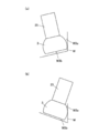
- FIG. 1st Embodiment of this invention An example of the workpiece
- the 2nd Embodiment of this invention it is the figure which showed the shape measurement state of the surface of a workpiece
- the shape of the probe of a modification is shown.
- the shape of the probe of a prior art example is shown, and it is a side view and a top view. It is the figure which showed the shape measurement state of the surface of a workpiece
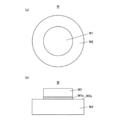
- the shape of the outer peripheral surface W1a of the workpiece W as shown in FIG. 1 can be suitably measured.
- the workpiece W is formed by stacking two cylinders W1 and W2 having different sizes, and in such a workpiece W, the upper surface W2a of the lower cylinder W2 among the outer peripheral surfaces of the upper cylinder W1 and It is possible to suitably measure the shape of the outer peripheral surface W1a adjacent to each other.
- the upper surface W2a of the cylinder W2 is a surface that intersects the outer peripheral surface W1a of the cylinder W1.
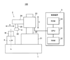
- the shape measuring apparatus 100 includes a probe 3, a probe support shaft 25 that pivotally supports the probe 3, and a probe support shaft 25 attached to the probe 3 at a measurement position on the outer circumferential surface W ⁇ b> 1 a of the workpiece W.
- a probe driving device 2 that makes the workpiece W and the probe 3 move relative to each other is provided.
- the probe driving device 2 includes a base 1, a base 21 fixed on the base 1, a Y-axis guide 22 fixed to the base 21 and extending in the Y direction, and supported by the Y-axis guide 22 in the Y direction.
- a Y stage 23 that moves in the Y direction (perpendicular to the X direction), an X stage 24 that is provided on the Y stage 23 to hold the probe 3 and moves the probe 3 in the X direction, and a base 1.
- the rotary stage 4 that rotatably supports the workpiece W, and the control device 5 that controls the operations of the Y stage 23, the X stage 24, and the rotary stage 4 are provided.
- the X stage 24 is attached with a probe support shaft 25 extending downward, and the probe 3 is attached to the tip of the probe support shaft 25.
- the X stage 24 has a movement amount displacement detector 241 that detects the movement amount of the X stage 24 in the X direction.
- the movement amount displacement detector 241 is connected to the control device 5 and outputs the movement amount detected by the movement amount displacement detector 241 to the control device 5.
- the probe 3 is a sphere 31 that is pivotally supported by the probe support shaft 25, and has a cut surface 32 that is cut out of the sphere 31 so as to be substantially perpendicular to the probe support shaft 25.
- the distance M in the vertical direction between the cut surface 32 and the apex 33 of the sphere 31 facing the equator surface 35 of the sphere 31 is not less than the radius R.
- the equator position 34 of the sphere 31 is configured to contact the measurement position of the outer peripheral surface W1a of the workpiece W.
- the distance N between the contact position (equatorial position 34) and the cut surface 32 in a direction substantially perpendicular to the cut surface 32 is 10 ⁇ m or more and 60 ⁇ m or less.
- the distance N is 10 ⁇ m or more and 60 ⁇ m or less, for example, as shown in FIG. 5B, even when the probe 3 is displaced from the probe support shaft 25, the installation displacement is absorbed by the distance N. can do.
- FIG. 5A shows an ideal state when the probe 3 and the probe support shaft 25 are installed.
- the above-described installation displacement cannot be absorbed, and when it exceeds 60 ⁇ m, the surface (the upper surface of the cylinder W2) that intersects the surface including the measurement position (the outer peripheral surface W1a). There is a possibility that the cut surface 32 comes into contact with and interferes with W2a).
- the cut surface 32 of the probe 3 is opposed to the surface (the upper surface W2a of the cylinder W2a) intersecting with the surface including the measurement position of the outer peripheral surface W1a of the workpiece W. Measurement is performed while pressing and contacting the equator position 34 with the measurement position of the workpiece W.
- the rotary stage 4 rotates around the rotation axis h passing through the approximate center of the workpiece W (see FIG. 2), and has an angular displacement detector 41 that detects the amount of angular movement of the rotary stage 4 as shown in FIG. ing.
- the angular displacement detector 41 is connected to the control device 5 and outputs the amount of movement detected by the angular displacement detector 41 to the control device 5.
- the workpiece W to be measured is installed on the rotary stage 4.
- the control device 5 is connected to an X stage 24, a Y stage 23, a rotary stage 4, a displacement displacement detector 241 and an angular displacement detector 41.
- the control device 5 includes a CPU (Central Processing Unit) 51, a RAM (Random Access Memory) 52, and a ROM (Read Only Memory) 53 (see FIG. 2), and operates the X stage 24, the Y stage 23, and the rotary stage 4. I have control.
- a program designated from various programs stored in the ROM 53 is expanded in the RAM 52, and various processes are executed in cooperation with the expanded program and the CPU 51.
- the cut surface 32 of the probe 3 is opposed to the surface (the upper surface W2a of the cylinder W2a) intersecting the surface including the measurement position of the outer peripheral surface W1a of the workpiece W, and the equator position 34 of the probe 3 is the outer peripheral surface of the workpiece W.
- the Y stage 23 and the X stage 24 are moved so as to come into contact with the measurement position of W1a.
- the X stage 24 is controlled so that the probe 3 has a constant pressing force against the workpiece W.
- the rotary stage 4 is rotated one or more times, the angular displacement amount of the rotary stage 4 and the movement displacement amount of the X stage 24 are synchronized at a predetermined interval, and the angular displacement amount and the movement displacement amount of the X stage 24 at that time are synchronized.
- Is detected by the angular displacement detector 41 and the displacement displacement detector 241, and the detected value is output to the CPU 51.
- the detection value output to the CPU 51 is stored in the RAM 52 as measurement data.
- the measurement data is a value obtained by offsetting the actual outer shape value of the workpiece W by the radius R of the sphere 31 of the probe 3
- the measurement data stored in the RAM 52 is used to offset the radius R by the normal direction.
- the ROM 53 stores the XY coordinate data of the center of the probe 3 in the initial state in advance
- the XY coordinate of the center of the probe 3 in the initial state the displacement displacement detector 41 and the angular displacement detector.
- the XY coordinates of the center of the probe 3 at the measurement position are calculated.
- the radius R at the contact position (equatorial position 34) of the probe 3 is offset with respect to the calculated measurement data.
- the outer peripheral shape data of the desired position of the workpiece W is collected by such measurement.
- the shape measuring apparatus 100 includes the probe 3, the probe support shaft 25, and the probe driving device 2, and the probe 3 is a sphere 31 that is pivotally supported by the probe support shaft 25. Since it has the cut surface 32 of the shape cut
- the sphere 31 can be used in a large state. Therefore, the rolling accuracy of the sphere 31 is high, and a more accurate sphere can be manufactured. Moreover, since the spherical body 31 can be enlarged, the attachment area with the probe support shaft 25 can be increased, the coupling force between the probe 3 and the probe support shaft 25 is increased, and handling is facilitated. Furthermore, since the probe support shaft 25 can be made thicker, the probe support shaft 25 can be prevented from bending, measurement errors caused by bending can be prevented, and highly accurate measurement can be performed.
- the vertical distance M between the cut surface 32 and the apex 33 of the sphere 31 facing the equator surface 35 of the sphere 31 is not less than the radius R of the sphere 31. Since the equator position 34 of the sphere 31 is brought into contact with the measurement position of the outer peripheral surface W1a of the work W among the surfaces of the sphere 31, the measurement can be performed with higher accuracy.
- the probe driving device 2 includes the X stage 24, the Y stage 23, the rotary stage 4 for rotating the workpiece W, and the control device 5 for controlling these operations, the probe W is moved while moving the probe 3 in the XY direction. By rotating, the probe 3 can be brought into contact with the measurement position of the outer peripheral surface W1a of the workpiece W accurately and reliably, and also in this respect, highly accurate measurement can be performed.
- the probe 3 can be moved in the Z direction with respect to the workpiece W, and the inclination of the probe support shaft 25 can be adjusted.
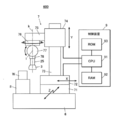
- the shape measuring apparatus 600 includes a probe 3, a probe support shaft 25 that supports the probe 3, and a probe support shaft 25 attached to the probe 3. ) And a probe driving device 7 for moving the workpiece W and the probe 3 relative to each other.
- the probe driving device 7 includes a base 6, a Z stage 71 provided on the base 6 and moving in the Z direction (Z direction perpendicular to the X direction and the Y direction), and a Z stage 71 provided on the Z stage 71.
- An X stage 72 that moves in the direction
- a Y-axis guide 73 that is fixed on the X stage 72 and extends in the Y direction, and is supported by the Y-axis guide 73 and moves in the Y direction (Y direction perpendicular to the X direction).
- Y stage 74 is provided on the Z stage 71.
- the probe driving device 7 includes a rotary stage 76 attached to the Y stage 74 via an attachment member 75, a tilt stage 77 attached to the lower surface of the rotary stage 76, an X stage 72, a Y stage 74, and a Z stage. 71, and a control device 9 for controlling the operation of the rotary stage 76 and the tilt stage 77.
- Rotation stage 76 rotates about vertical axis k.
- the tilt stage 77 adjusts the inclination of the probe 3 by moving in an arc around the rotation center i disposed on the probe support shaft 25.
- a contact displacement sensor 78 is attached to the lower surface of the tilt stage 77.
- the contact displacement sensor 78 detects the contact position when the probe 3 comes into contact with the measurement position of the workpiece W and outputs it to the control device 9.
- the probe support shaft 25 extending downward is attached to the lower surface of the contact displacement sensor 78, and the probe 3 is attached to the lower end portion of the probe support shaft 25.
- the X stage 72, the Y stage 74, and the Z stage 71 have movement amount displacement detectors 721, 741, and 711 that detect respective movement amounts in the X direction, the Y direction, and the Z direction. ing. These movement amount displacement detectors 721, 741, 711 are connected to the control device 9, and the movement displacement amounts detected by the movement amount displacement detectors 721, 741, 711 are output to the control device 9.
- the rotary stage 76 and the tilt stage 77 have angular displacement detectors 761 and 771 that detect the angular displacement amounts of the rotary stage 76 and the tilt stage 77, respectively.
- the angular displacement detectors 761 and 771 are connected to the control device 9 and output the amount of angular displacement detected by the angular displacement detectors 761 and 771 to the control device 9.
- the probe 3 can be the same as the probe 3 in the first embodiment, and is a sphere 31 that is pivotally supported by the probe support shaft 25 and is substantially perpendicular to the probe support shaft 25 of the sphere 31.
- the cut surface 32 is shaped so as to be cut.
- the workpiece W to be measured includes, for example, a workpiece W3b that intersects with the outer peripheral surface W3a including the measurement position is inclined with respect to the outer peripheral surface W3a as shown in FIG.
- the workpiece W to be measured is installed on the support base 8.
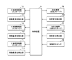
- the control device 9 includes an X stage 72, a Y stage 74, a Z stage 71, a rotary stage 76, a tilt stage 77, displacement displacement detectors 721, 741, 711, and angular displacement detectors 761, 771. And a contact displacement sensor 78.
- the control device 9 includes a CPU (Central Processing Unit) 91, a RAM (Random Access Memory) 92, and a ROM (Read Only Memory) 93 (see FIG. 6), an X stage 72, a Y stage 74, a Z stage 71, and a rotating stage. 76, the operation of the tilt stage 77 is controlled.
- a program designated from various programs stored in the ROM 93 is expanded in the RAM 92, and various processes are executed in cooperation with the expanded program and the CPU 91.
- the cut surface 32 of the probe 3 is opposed to the surface W3b intersecting the surface including the measurement position of the outer peripheral surface W3a of the workpiece W,
- the X stage 72, the Y stage 74, the Z stage 71, the rotary stage 76, and the tilt stage 77 are moved so that the equator position 34 of the probe 3 comes into contact with the measurement position of the outer peripheral surface W3a of the workpiece W.
- the probe 3 is brought into contact with the cut surface 32 of the probe 3 so as to avoid the surface W3b intersecting the outer peripheral surface W3a including the measurement position.
- the contact position is detected by the contact displacement sensor 78, and the probe support shaft 25 is stopped at that position.
- the angular displacement amounts of the rotary stage 76 and the tilt stage 77 are detected by the angular displacement detectors 761 and 771, and simultaneously, the displacement movement amounts of the X stage 72, the Y stage 74, and the Z stage 71 are detected as the movement amount displacement detector 721. , 741, 711 and the detected value is output to the CPU 91.
- the detection value output to the CPU 91 is stored in the RAM 92 as measurement data. This operation is repeated to collect measurement data at a desired position of the workpiece W.
- the measurement data is a value obtained by offsetting the actual outer shape value of the workpiece W by the radius R of the sphere 31 of the probe 3
- the measurement data stored in the RAM 92 is used to offset the radius R in the normal direction. To obtain the actual value of the workpiece W.
- the second embodiment also includes the probe 3, the probe support shaft 25, and the probe driving device 7, as in the first embodiment, and the probe 3 is attached to the probe support shaft 25. Since the supported sphere 31 has the cut surface 32 of the sphere 31 that is cut so as to be substantially perpendicular to the probe support shaft 25, the same effect as in the first embodiment is obtained. Obtainable.
- the probe driving device 7 in the second embodiment includes the X stage 72, the Y stage 74, the Z stage 71, the rotary stage 76, the tilt stage 77, and the control device 9, the probe 3 is moved in the XYZ directions. Even if the workpiece W has a complicated shape or a surface that causes interference in measurement, it can easily correspond to the measurement position. As a result, the probe 3 can be surely brought into contact with each other and more accurate measurement can be performed.
- the present invention is not limited to the above embodiment, and can be appropriately changed without departing from the gist of the invention.
- the probe 3 may be provided with an interference cut surface 36 obtained by cutting a part of the surface of the sphere 31 except the cut surface 32.
- an interference cut surface 36 obtained by cutting a part of the surface of the sphere 31 except the cut surface 32.
- work with the curved surface may be sufficient, and it can change suitably. .
- Probe drive device 3 Probe 5, 9 Control device 23, 74 Y stage (Y axis movement mechanism) 24,72 X stage (X axis movement mechanism) 25 Probe support shaft 31 Sphere 32 Cut surface 33 Vertex 34 Equatorial position 35 Equatorial surface 36 Interference cut surface 76 Rotating stage (rotating mechanism) 77 Aori Stage (Aori Mechanism) 71 Z stage (Z axis movement mechanism) 100,600 Shape measuring device W Work M, N Distance
Landscapes
- Physics & Mathematics (AREA)
- General Physics & Mathematics (AREA)
- A Measuring Device Byusing Mechanical Method (AREA)
- Length Measuring Devices With Unspecified Measuring Means (AREA)
- Machine Tool Sensing Apparatuses (AREA)
Abstract
Priority Applications (4)
| Application Number | Priority Date | Filing Date | Title |
|---|---|---|---|
| CN2010800129756A CN102362143B (zh) | 2009-03-24 | 2010-02-15 | 形状测定装置 |
| JP2011505927A JP4748287B2 (ja) | 2009-03-24 | 2010-02-15 | 形状測定装置 |
| EP10755776.1A EP2413090B1 (fr) | 2009-03-24 | 2010-02-15 | Dispositif de mesure de la forme |
| US13/258,255 US8561309B2 (en) | 2009-03-24 | 2010-02-15 | Shape measuring device |
Applications Claiming Priority (2)
| Application Number | Priority Date | Filing Date | Title |
|---|---|---|---|
| JP2009071420 | 2009-03-24 | ||
| JP2009-071420 | 2009-03-24 |
Publications (1)
| Publication Number | Publication Date |
|---|---|
| WO2010109975A1 true WO2010109975A1 (fr) | 2010-09-30 |
Family
ID=42780671
Family Applications (1)
| Application Number | Title | Priority Date | Filing Date |
|---|---|---|---|
| PCT/JP2010/052162 WO2010109975A1 (fr) | 2009-03-24 | 2010-02-15 | Dispositif de mesure de la forme |
Country Status (7)
| Country | Link |
|---|---|
| US (1) | US8561309B2 (fr) |
| EP (1) | EP2413090B1 (fr) |
| JP (1) | JP4748287B2 (fr) |
| KR (1) | KR20120006979A (fr) |
| CN (1) | CN102362143B (fr) |
| TW (1) | TWI473967B (fr) |
| WO (1) | WO2010109975A1 (fr) |
Cited By (1)
| Publication number | Priority date | Publication date | Assignee | Title |
|---|---|---|---|---|
| JP7471485B1 (ja) | 2023-03-01 | 2024-04-19 | 株式会社牧野フライス製作所 | タッチプローブ |
Families Citing this family (7)
| Publication number | Priority date | Publication date | Assignee | Title |
|---|---|---|---|---|
| CN103455045A (zh) * | 2012-05-30 | 2013-12-18 | 鸿富锦精密工业(深圳)有限公司 | 接触式运动控制系统及方法 |
| JP6169339B2 (ja) * | 2012-10-04 | 2017-07-26 | 株式会社日立製作所 | 形状計測方法及び装置 |
| GB201311600D0 (en) * | 2013-06-28 | 2013-08-14 | Renishaw Plc | Calibration of a contact probe |
| CN104316547B (zh) * | 2014-11-05 | 2017-04-19 | 同方威视技术股份有限公司 | 一种用于x射线检查设备的旋转弧形探测器盒 |
| KR101915948B1 (ko) * | 2016-10-31 | 2019-01-30 | 창원대학교 산학협력단 | 복합 형상 측정기 |
| US10969760B2 (en) | 2018-04-12 | 2021-04-06 | Faro Technologies, Inc. | Coordinate measurement system with auxiliary axis |
| US11874101B2 (en) | 2018-04-12 | 2024-01-16 | Faro Technologies, Inc | Modular servo cartridges for precision metrology |
Citations (10)
| Publication number | Priority date | Publication date | Assignee | Title |
|---|---|---|---|---|
| JPS507458U (fr) * | 1973-05-21 | 1975-01-25 | ||
| JPS63150601A (ja) * | 1986-12-09 | 1988-06-23 | エ−ロ−ヴア・ア−・ゲ− | 物体の寸法も三次元的に測定する測定装置 |
| JPH06288704A (ja) * | 1993-04-06 | 1994-10-18 | Toshiba Ceramics Co Ltd | 内径測定装置 |
| JPH09133512A (ja) * | 1995-11-07 | 1997-05-20 | Sanyo Mach Works Ltd | 光学式三次元測定方法 |
| JPH11125520A (ja) * | 1997-10-21 | 1999-05-11 | Matsushita Electric Ind Co Ltd | 半導体ウエハ支持用部材及び半導体ウエハの平面度測定装置 |
| JP2001280947A (ja) | 2000-03-29 | 2001-10-10 | Mitsutoyo Corp | 形状測定機及び形状測定方法 |
| JP2002022433A (ja) * | 2000-05-01 | 2002-01-23 | Mitsutoyo Corp | ワーク形状測定センサおよびワーク形状測定装置 |
| JP2002357415A (ja) | 2001-06-04 | 2002-12-13 | Matsushita Electric Ind Co Ltd | 形状測定装置及び方法、被測定物の製造方法 |
| JP2005147673A (ja) * | 2003-11-11 | 2005-06-09 | Nissan Motor Co Ltd | 三次元座標測定用プローブとそのプローブを用いた三次元座標測定装置 |
| JP2006125934A (ja) | 2004-10-27 | 2006-05-18 | Matsushita Electric Ind Co Ltd | 測定用プローブと測定方法 |
Family Cites Families (12)
| Publication number | Priority date | Publication date | Assignee | Title |
|---|---|---|---|---|
| JPS507458A (fr) * | 1973-05-18 | 1975-01-25 | ||
| GB8629437D0 (en) * | 1986-12-09 | 1987-01-21 | Reinshaw Plc | Displacement-sensing probe |
| GB8815984D0 (en) * | 1988-07-05 | 1988-08-10 | Univ Brunel | Probes |
| GB8906287D0 (en) * | 1989-03-18 | 1989-05-04 | Renishaw Plc | Probe calibration |
| JP2000304529A (ja) * | 1999-04-22 | 2000-11-02 | Ricoh Co Ltd | プローブ装置及び形状測定装置 |
| GB0126232D0 (en) * | 2001-11-01 | 2002-01-02 | Renishaw Plc | Calibration of an analogue probe |
| GB0608235D0 (en) * | 2006-04-26 | 2006-06-07 | Renishaw Plc | Differential calibration |
| JP5221004B2 (ja) * | 2006-05-25 | 2013-06-26 | 株式会社ミツトヨ | 測定装置、表面性状測定方法、及び表面性状測定プログラム |
| DE102007051054A1 (de) * | 2007-10-19 | 2009-04-30 | Carl Zeiss Industrielle Messtechnik Gmbh | Verfahren zum Korrigieren der Messwerte eines Koordinatenmessgeräts und Koordinatenmessgerät |
| DE102009049534A1 (de) * | 2009-10-06 | 2011-04-07 | Carl Zeiss Industrielle Messtechnik Gmbh | Koordinatenmessgerät mit Lageänderungssensoren |
| EP2385339A1 (fr) * | 2010-05-05 | 2011-11-09 | Leica Geosystems AG | Dispositif de détection de surface doté d'un système de surveillance optique |
| JP5612386B2 (ja) * | 2010-07-23 | 2014-10-22 | 株式会社ミツトヨ | 形状測定装置 |
-
2010
- 2010-02-15 CN CN2010800129756A patent/CN102362143B/zh not_active Expired - Fee Related
- 2010-02-15 WO PCT/JP2010/052162 patent/WO2010109975A1/fr active Application Filing
- 2010-02-15 US US13/258,255 patent/US8561309B2/en active Active
- 2010-02-15 EP EP10755776.1A patent/EP2413090B1/fr not_active Not-in-force
- 2010-02-15 JP JP2011505927A patent/JP4748287B2/ja active Active
- 2010-02-15 KR KR1020117021920A patent/KR20120006979A/ko not_active Application Discontinuation
- 2010-03-18 TW TW99108006A patent/TWI473967B/zh not_active IP Right Cessation
Patent Citations (10)
| Publication number | Priority date | Publication date | Assignee | Title |
|---|---|---|---|---|
| JPS507458U (fr) * | 1973-05-21 | 1975-01-25 | ||
| JPS63150601A (ja) * | 1986-12-09 | 1988-06-23 | エ−ロ−ヴア・ア−・ゲ− | 物体の寸法も三次元的に測定する測定装置 |
| JPH06288704A (ja) * | 1993-04-06 | 1994-10-18 | Toshiba Ceramics Co Ltd | 内径測定装置 |
| JPH09133512A (ja) * | 1995-11-07 | 1997-05-20 | Sanyo Mach Works Ltd | 光学式三次元測定方法 |
| JPH11125520A (ja) * | 1997-10-21 | 1999-05-11 | Matsushita Electric Ind Co Ltd | 半導体ウエハ支持用部材及び半導体ウエハの平面度測定装置 |
| JP2001280947A (ja) | 2000-03-29 | 2001-10-10 | Mitsutoyo Corp | 形状測定機及び形状測定方法 |
| JP2002022433A (ja) * | 2000-05-01 | 2002-01-23 | Mitsutoyo Corp | ワーク形状測定センサおよびワーク形状測定装置 |
| JP2002357415A (ja) | 2001-06-04 | 2002-12-13 | Matsushita Electric Ind Co Ltd | 形状測定装置及び方法、被測定物の製造方法 |
| JP2005147673A (ja) * | 2003-11-11 | 2005-06-09 | Nissan Motor Co Ltd | 三次元座標測定用プローブとそのプローブを用いた三次元座標測定装置 |
| JP2006125934A (ja) | 2004-10-27 | 2006-05-18 | Matsushita Electric Ind Co Ltd | 測定用プローブと測定方法 |
Cited By (1)
| Publication number | Priority date | Publication date | Assignee | Title |
|---|---|---|---|---|
| JP7471485B1 (ja) | 2023-03-01 | 2024-04-19 | 株式会社牧野フライス製作所 | タッチプローブ |
Also Published As
| Publication number | Publication date |
|---|---|
| JP4748287B2 (ja) | 2011-08-17 |
| EP2413090A1 (fr) | 2012-02-01 |
| TW201105927A (en) | 2011-02-16 |
| KR20120006979A (ko) | 2012-01-19 |
| TWI473967B (zh) | 2015-02-21 |
| EP2413090B1 (fr) | 2018-06-06 |
| EP2413090A4 (fr) | 2015-04-15 |
| CN102362143A (zh) | 2012-02-22 |
| US20120017455A1 (en) | 2012-01-26 |
| US8561309B2 (en) | 2013-10-22 |
| CN102362143B (zh) | 2013-11-13 |
| JPWO2010109975A1 (ja) | 2012-09-27 |
Similar Documents
| Publication | Publication Date | Title |
|---|---|---|
| JP4748287B2 (ja) | 形状測定装置 | |
| US10073435B2 (en) | Reducing errors of a rotatory device, in particular for the determination of coordinates of a workpiece or the machining of a workpiece | |
| US6327788B1 (en) | Surface form measurement | |
| JP5332009B2 (ja) | 形状測定装置、及び形状測定方法 | |
| US6112423A (en) | Apparatus and method for calibrating a probe assembly of a measuring machine | |
| JP6126359B2 (ja) | 球体形状測定装置 | |
| JP5277033B2 (ja) | 補正ボール径算出方法および形状測定装置 | |
| JP5060915B2 (ja) | スタイラス、形状測定機及びパートプログラム | |
| US11592278B2 (en) | Method and apparatus for determining a relative position of an axis of rotation of a rotary table for a coordinate measuring machine | |
| EP2312264A1 (fr) | Procédé d'étalonnage de la quantité de décalage et machine de mesure de profile de surface | |
| JP5600045B2 (ja) | 三次元測定機の校正方法 | |
| JP6368986B1 (ja) | 検出器、表面性状測定機、及び真円度測定機 | |
| JP2021094600A (ja) | 工作機械及びワーク加工部の形状測定方法 | |
| WO2020213432A1 (fr) | Détecteur de déplacement, instrument de mesure de texture de surface et instrument de mesure de rondeur | |
| JP4417121B2 (ja) | 被測定物の通り出し方法、及び表面性状測定装置 | |
| CN112050711A (zh) | 用于测量装置的回转测头和测量装置 | |
| JP2009180700A (ja) | 円筒形状測定装置および円筒の表面形状測定方法 | |
| CN1177732A (zh) | 利用球形探头的坐标测量装置 | |
| JP2005103667A (ja) | 自由曲面加工装置 | |
| JP6361729B2 (ja) | 非球面の偏心量測定方法及び形状解析方法 | |
| JP5218957B2 (ja) | 形状測定装置、形状測定方法、及び形状測定プログラム | |
| JP7360593B2 (ja) | 校正ユニット | |
| CN109397090A (zh) | 测量装置 | |
| JP2023017410A (ja) | 測定装置および穴位置検出方法 | |
| JP2012232395A (ja) | 工作機械における位置ずれ補正方法 |
Legal Events
| Date | Code | Title | Description |
|---|---|---|---|
| WWE | Wipo information: entry into national phase |
Ref document number: 201080012975.6 Country of ref document: CN |
|
| 121 | Ep: the epo has been informed by wipo that ep was designated in this application |
Ref document number: 10755776 Country of ref document: EP Kind code of ref document: A1 |
|
| WWE | Wipo information: entry into national phase |
Ref document number: 2011505927 Country of ref document: JP |
|
| ENP | Entry into the national phase |
Ref document number: 20117021920 Country of ref document: KR Kind code of ref document: A |
|
| WWE | Wipo information: entry into national phase |
Ref document number: 13258255 Country of ref document: US Ref document number: 2010755776 Country of ref document: EP |
|
| NENP | Non-entry into the national phase |
Ref country code: DE |