WO2010109968A1 - 駆動装置の製造方法及びこの製造方法で製造された駆動装置 - Google Patents
駆動装置の製造方法及びこの製造方法で製造された駆動装置 Download PDFInfo
- Publication number
- WO2010109968A1 WO2010109968A1 PCT/JP2010/052050 JP2010052050W WO2010109968A1 WO 2010109968 A1 WO2010109968 A1 WO 2010109968A1 JP 2010052050 W JP2010052050 W JP 2010052050W WO 2010109968 A1 WO2010109968 A1 WO 2010109968A1
- Authority
- WO
- WIPO (PCT)
- Prior art keywords
- sliding surface
- drive shaft
- manufacturing
- drive device
- piezoelectric element
- Prior art date
- Legal status (The legal status is an assumption and is not a legal conclusion. Google has not performed a legal analysis and makes no representation as to the accuracy of the status listed.)
- Ceased
Links
Images



Classifications
-
- H—ELECTRICITY
- H02—GENERATION; CONVERSION OR DISTRIBUTION OF ELECTRIC POWER
- H02N—ELECTRIC MACHINES NOT OTHERWISE PROVIDED FOR
- H02N2/00—Electric machines in general using piezoelectric effect, electrostriction or magnetostriction
- H02N2/02—Electric machines in general using piezoelectric effect, electrostriction or magnetostriction producing linear motion, e.g. actuators; Linear positioners ; Linear motors
- H02N2/021—Electric machines in general using piezoelectric effect, electrostriction or magnetostriction producing linear motion, e.g. actuators; Linear positioners ; Linear motors using intermittent driving, e.g. step motors, piezoleg motors
- H02N2/025—Inertial sliding motors
-
- G—PHYSICS
- G02—OPTICS
- G02B—OPTICAL ELEMENTS, SYSTEMS OR APPARATUS
- G02B6/00—Light guides; Structural details of arrangements comprising light guides and other optical elements, e.g. couplings
- G02B6/24—Coupling light guides
- G02B6/42—Coupling light guides with opto-electronic elements
- G02B6/4201—Packages, e.g. shape, construction, internal or external details
- G02B6/4219—Mechanical fixtures for holding or positioning the elements relative to each other in the couplings; Alignment methods for the elements, e.g. measuring or observing methods especially used therefor
- G02B6/422—Active alignment, i.e. moving the elements in response to the detected degree of coupling or position of the elements
- G02B6/4226—Positioning means for moving the elements into alignment, e.g. alignment screws, deformation of the mount
-
- G—PHYSICS
- G02—OPTICS
- G02B—OPTICAL ELEMENTS, SYSTEMS OR APPARATUS
- G02B7/00—Mountings, adjusting means, or light-tight connections, for optical elements
- G02B7/003—Alignment of optical elements
- G02B7/005—Motorised alignment
-
- G—PHYSICS
- G02—OPTICS
- G02B—OPTICAL ELEMENTS, SYSTEMS OR APPARATUS
- G02B7/00—Mountings, adjusting means, or light-tight connections, for optical elements
- G02B7/02—Mountings, adjusting means, or light-tight connections, for optical elements for lenses
- G02B7/023—Mountings, adjusting means, or light-tight connections, for optical elements for lenses permitting adjustment
-
- H—ELECTRICITY
- H02—GENERATION; CONVERSION OR DISTRIBUTION OF ELECTRIC POWER
- H02N—ELECTRIC MACHINES NOT OTHERWISE PROVIDED FOR
- H02N2/00—Electric machines in general using piezoelectric effect, electrostriction or magnetostriction
- H02N2/0005—Electric machines in general using piezoelectric effect, electrostriction or magnetostriction producing non-specific motion; Details common to machines covered by H02N2/02 - H02N2/16
- H02N2/005—Mechanical details, e.g. housings
- H02N2/0065—Friction interface
Definitions
- the present invention relates to a method of manufacturing a drive device for a linear piezoelectric actuator and a drive device manufactured by the manufacturing method.
- an optical device such as a laser module that emits laser light has a plurality of optical elements for coupling outgoing light emitted from a light source to an incident end face of a waveguide such as a SHG (Second Harmonic Generation) element or an optical fiber. Some are arranged with their optical axes aligned.
- optical elements those requiring high alignment accuracy are provided with driving means, and by shifting the optical elements with this driving means, the emitted light is coupled to the incident end face of the waveguide with high accuracy, It is also possible to correct for changes in optical performance due to temperature changes of the optical elements.
- SIDM smooth Impact Drive Mechanism
- This SIDM device is a linear piezoelectric actuator that reciprocates a moving body in the order of nanometers by applying a voltage, a piezoelectric element that expands and contracts by applying a voltage, a drive shaft that displaces by expansion and contraction of the piezoelectric element, and a piezoelectric element Or a support member that supports the drive shaft and a moving body that is frictionally engaged with the drive shaft and moves in the axial direction of the drive shaft, and includes a rapid volume change of the piezoelectric element and an inertial force of the moving body.
- the moving body is moved in the axial direction of the drive shaft using the frictional force.
- the SIDM device is a kind of linear piezoelectric actuator, and will be described as an example of a drive device according to the present invention. However, the present invention is also applicable to linear piezoelectric actuators other than the SIDM device.
- the moving body may not move, and durability is improved. bad.
- the drive shaft is formed of a composite material of a polymer material and a fiber bundle, and the polymer material is removed from the sliding surface of the drive shaft with the moving body to expose the fiber bundle.
- a technique for bringing a fiber bundle into contact with a moving body has been developed (see, for example, Patent Document 1).
- Patent Document 1 the surface of the polymer material that binds the exposure of the fiber bundle is polished by a polishing agent containing fine abrasive grains.
- An object of the present invention is to provide a method for manufacturing a driving device capable of improving durability as compared with the prior art and a driving device manufactured by this manufacturing method.
- a piezoelectric element that expands and contracts by application of voltage Formed of a composite material of resin and fiber bundle, the piezoelectric element is attached to one end, and a columnar drive shaft that is displaced by expansion and contraction of the piezoelectric element;
- Lapping treatment for flattening the sliding surface so that the resin and the fiber bundle are exposed at the same height on the sliding surface of the drive shaft with respect to the moving body; Polishing treatment to polish the sliding surface so as to remove only the resin on the sliding surface; After going in this order, An assembling step of frictionally engaging the movable body with the drive shaft is performed.
- the sliding surface is planarized until the flatness of the sliding surface becomes 1 to 2 ⁇ m.
- the sliding surface is polished until the flatness of the sliding surface becomes 3 to 4 ⁇ m.
- a moving body flattening process is performed in which lapping or cutting is performed on the sliding surface so that a planar roughness value Ra of the sliding surface of the moving body with respect to the drive shaft is 1 ⁇ m or less.
- the drive shaft is a prismatic one.
- a sixth aspect of the present invention is the method of manufacturing a drive device according to any one of the first to fifth aspects,
- the fiber bundle of the drive shaft is a carbon fiber.
- the invention described in claim 7 A piezoelectric element that expands and contracts by application of voltage; Formed of a composite material of resin and fiber bundle, the piezoelectric element is attached to one end, and a columnar drive shaft that is displaced by expansion and contraction of the piezoelectric element; A support portion for supporting the piezoelectric element or the drive shaft;
- a drive device comprising a moving body that is frictionally engaged with the drive shaft and moves in the axial direction of the drive shaft, It is manufactured by the method for manufacturing a drive device according to any one of claims 1 to 6.
- FIG. 1 It is a conceptual diagram which shows schematic structure of a light source unit. It is a figure which shows a SIDM apparatus. It is a figure for demonstrating the manufacturing method of a SIDM apparatus. It is a table
- FIG. 1 is a conceptual diagram showing a schematic configuration of a light source unit 100 in the present embodiment.
- a light source unit 100 includes an infrared semiconductor laser 11 that irradiates laser light inside a package 10 and an optical element (collimator lens) that converts the laser light from the infrared semiconductor laser 11 into a parallel beam. 12, an optical element (condensing lens) 13 that condenses the light beam from the optical element 12, and a PPLN (Periodically Poled Lithium Niobate) waveguide 14 as a SHG (Second Harmonic Generation) element.
- the shaded portion in the figure indicates the luminous flux.
- the light source unit 100 has a maximum length of 10 mm or less, and the optical elements 12 and 13 have a maximum diameter of 10 mm or less, specifically about 4 mm.
- the PPLN waveguide 14 is provided with a temperature control plate 16 for controlling the temperature of the PPLN waveguide 14.
- these members in the light source unit 100 for example, those disclosed in the following documents 1 and 2 can be used.
- the SIDM devices 1A and 1B are ultra-compact and high-precision actuators that use a piezoelectric element as a drive source.
- the optical element 12 is the Z-axis direction in the figure
- the optical element 13 is the Y-axis in the figure. It is possible to move in the direction.
- the SIDM apparatus 1A may move the optical element 12 in the Y-axis direction
- the SIDM apparatus 1B may move the optical element 13 in the Z-axis direction
- the SIDM apparatuses 1A and 1B may move in the Z-axis direction and the Y-axis direction.
- the optical elements 12 and 13 may be moved in the X-axis direction. Details of the SIDM devices 1A and 1B will be described later.
- a control unit (not shown) is connected to the above SIDM devices 1A and 1B.
- the control unit drives the SIDM devices 1A and 1B to move the optical elements 12 and 13, respectively, so that the optical axes of the optical elements 12 and 13 are set to the incident end faces of the infrared semiconductor laser 11 and the PPLN waveguide 14. It can be adjusted (aligned).
- the light source unit 100 as described above can be used as a green light source in a conventionally known image projection apparatus, for example.
- SIDM devices 1A and 1B will be described in detail.
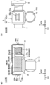
- FIG. 2 is a diagram showing a schematic configuration of SIDM devices 1A and 1B (hereinafter referred to as SIDM device 1) as drive devices according to the present invention.
- the SIDM apparatus 1 includes a piezoelectric element 2, a drive shaft 3, a base member 4, a moving body 5, and the like.
- the piezoelectric element 2 expands and contracts when a voltage is applied, and is a piezo element in the present embodiment.
- the expansion / contraction direction of the piezoelectric element 2 is the Z-axis direction in the SIDM apparatus 1A and the Y-axis direction in the SIDM apparatus 1B. Further, a voltage is applied to the piezoelectric element 2 from a control device (not shown).
- the drive shaft 3 is a columnar member, which is a quadrangular columnar member in the present embodiment, and is fixed to one end of the piezoelectric element 2 and is displaced by the expansion and contraction of the piezoelectric element 2.
- the drive shaft may be cylindrical, but the prismatic shape is more effective in obtaining accuracy.
- the displacement direction of the drive shaft 3 is the Z-axis direction in the SIDM apparatus 1A and the Y-axis direction in the SIDM apparatus 1B.
- the base member 4 is a support portion in the present invention, and is fixed to the other end of the piezoelectric element 2 and is fixed to the blanket 18 of FIG. Thereby, the base member 4 is configured to support the piezoelectric element 2 so as to extend and contract while restricting the movement of the piezoelectric element 2. That is, the displacement direction of the piezoelectric element 2 is limited only to the drive shaft 3 side.
- the base member 4 is directly fixed to the other end of the piezoelectric element 2, but may be fixed via an absorbent body such as a sponge.
- the base member 4 may be fixed to the side peripheral surface of the piezoelectric element 2 or may be fixed to the side peripheral surface of the drive shaft 3.
- the base member 4 supports the piezoelectric element 2 via the drive shaft 3. In this case, although the piezoelectric element 2 is in the air fishing state, it vibrates by voltage application and can transmit the vibration to the drive shaft 3.
- the moving body 5 slides in the axial direction with respect to the drive shaft 3 and is frictionally engaged with the drive shaft 3.
- the moving body 5 has a moving body main body 50 and an urging member 6.
- the movable body 50 is a substantially concave member provided with a groove 51 extending in the axial direction of the drive shaft 3, and four side peripheral surfaces 3 a to 3 d of the drive shaft 3 on the inner surface 52 of the groove 51. Of these, the two side surfaces 3a and 3b are in contact with each other. Two engaging claws 50 b and 50 c that engage with the urging member 6 are provided on the outer surface 53 of the groove 51 in the movable body 50.
- the mobile body 50 is made of zinc or SUS.
- the optical element 12 (or 13) is fixed to the movable body 50 via the lens barrel 102, and the optical axis direction of the optical element 12 (or 13) depends on which of the SIDM devices 1A and 1B. Is also in the X-axis direction.
- FIG. 2 only the optical element 12 supported by the SIDM apparatus 1A is shown for simplification of illustration, and in the SIDM apparatus 1B, the fixed positions of the lens barrel 102 and the optical element 13 with respect to the moving body 50 are shown. Is different from the SIDM apparatus 1A.
- the urging member 6 urges the drive shaft 3 to the inner side surface 52 of the groove 51, and includes a plate spring 61 and a coil spring 62.
- the leaf spring 61 is a substantially U-shaped leaf spring, and has two holes 61b and 61c at both ends.
- the leaf spring 61 is fixed to the outer surface 53 of the groove 51 across the groove 51 by engaging the holes 61 b and 61 c with the engaging claws 50 b and 50 c of the moving body 50.
- the central portion of the leaf spring 61 is recessed inward, and this recessed portion abuts against the sliding plate 61a and biases the drive shaft 3 to the inner side surface 52 of the groove portion 51 via the sliding plate 61a.
- the sliding plate 61a is made of SUS.
- the urging direction by the leaf spring 61 is the Y-axis direction in the SIDM apparatus 1A and the X direction in the SIDM apparatus 1B.
- the coil spring 62 is disposed inside the groove 51 and biases the drive shaft 3 toward the inner surface 52 of the groove 51 via a sliding plate 62a made of SUS.
- the biasing direction by the coil spring 62 is the X direction in the SIDM apparatus 1A and the Z direction in the SIDM apparatus 1B.
- the sliding plates 61a and 62a can be omitted.
- a saw-tooth wave drive pulse that rises gently and falls rapidly is applied to the piezoelectric element 2.
- the piezoelectric element 2 gently expands, and the drive shaft 3 gently moves in the positive direction of the Z-axis (or Y-axis) (the direction from right to left in FIG. 2B).
- the moving body 5 moves in the positive direction of the Z axis (or Y axis) together with the drive shaft 3 by the frictional engagement force with the drive shaft 3.
- the waveform of the sawtooth wave drive pulse applied to the piezoelectric element 2 is changed.
- a waveform that rises rapidly and falls slowly may be used.
- the applied drive waveform is not limited to the sawtooth drive pulse shown here, but a rectangular wave having a duty ratio suitable for driving or a waveform having rising / falling characteristics suitable for other driving is applied. It is also possible to do.
- FIG. 3 is a conceptual diagram showing the fine structure of the sliding surface 30 (see FIG. 2) of the drive shaft 3 with respect to the moving body 5.
- the drive shaft 3 is cut out from the plate-like member. At this time, the surface of the drive shaft 3 is in a state as shown in FIG.
- the sliding surface 30 is flattened so that the resin J and the carbon fiber C on the sliding surface 30 of the drive shaft 3 are flush with each other (lapping process). ). More specifically, in this lapping process, the sliding surface 30 is planarized until the flatness of the sliding surface 30 becomes 1 to 2 ⁇ m. In the present embodiment, the entire side peripheral surface of the drive shaft 3 is lapped.
- a commercially available lapping film sheet for example, one having a particle size of 3 ⁇ m and abrasive grains of aluminum oxide can be used.
- the flatness is a value of the maximum height difference, and more specifically, a value of the height difference between the most protruding portion and the most depressed portion. That is, when the lapping process is performed until the flatness becomes 1 to 2 ⁇ m, both the resin J and the carbon fiber C are scraped, and the maximum height difference is 1 to 2 ⁇ m, which is a plane having almost the same height.
- the sliding surface 30 is polished so as to remove only the resin J on the sliding surface 30 (polishing treatment). More specifically, in this polishing process, the sliding surface 30 is polished until the flatness of the sliding surface 30 becomes 3 to 4 ⁇ m. Since only the resin J is polished by this polishing process, only the carbon fiber C made flat by the lapping process is exposed on the sliding surface 30.
- Such a polishing treatment can be performed with a material having a hardness lower than that of the carbon fiber C and higher than that of the resin J.
- the entire side peripheral surface of the drive shaft 3 is polished.
- the sliding roughness 500 of the sliding surface 500 (see FIG. 2) of the movable body 5 with respect to the drive shaft 3 is 1 ⁇ m or less. Lapping or cutting is performed on the moving surface 500 (moving body flattening process).
- a “2000” file (abrasive paper) can be used for lapping, and a milling tool can be used for cutting.
- a “2000” file abrasive paper
- a milling tool can be used for cutting.
- the moving body 5 is not formed by die casting, for example, when it is formed by machining, it can be sufficiently smoothed by processing, and therefore the moving body flattening process may not be performed.
- the sliding surfaces are mirror finished so that the flatness of the sliding surfaces of the sliding plates 61a and 62a with respect to the drive shaft 3 is 1 ⁇ m or less.
- the SIDM apparatus 1 is assembled (assembly process)
- heating at 120 ° C. for 1 hour is repeated four times or more to cure the adhesive between the members.
- the SIDM device 1 is manufactured.
- the sliding surface 30 is flattened until the flatness of the sliding surface 30 becomes 1 to 2 ⁇ m, and in the polishing process, the sliding surface 30 is flattened until the flatness of the sliding surface 30 becomes 3 to 4 ⁇ m. Since the surface 30 is polished, the sliding surface 30 of the drive shaft 3 can be a smooth surface with only the carbon fiber C exposed. Therefore, the durability of the SIDM device 1 can be further improved.
- the sliding surface 500 is lapped or cut so that the planar roughness value Ra of the sliding surface 500 of the moving body 5 is 1 ⁇ m or less, the sliding surface of the moving body 5 with respect to the drive shaft 3. 500 can be smoothed. Therefore, the durability of the SIDM device 1 can be further improved.
- the sliding surfaces of the sliding plates 61a and 62a are mirror-finished so that the flatness of the sliding surfaces of the sliding plates 61a and 62a is 1 ⁇ m or less, so that the sliding surfaces of the sliding plates 61a and 62a with respect to the drive shaft 3 are smoothed. can do. Therefore, the durability of the SIDM device 1 can be further improved.
- the flatness of the sliding surface 30 is cut after being cut out from a plate-shaped member made of a composite material of heat-resistant epoxy resin and carbon fiber (fiber bundle) as the drive shaft 3. What was lapped to 1 to 2 ⁇ m was used, and the moving body 5 formed by die casting from zinc was used as it was.
- the flatness of the sliding surface 30 is 1 after being cut out from the plate-shaped member of the composite material of the heat-resistant epoxy resin and the carbon fiber (fiber bundle) as the drive shaft 3. What was lapped to ⁇ 2 ⁇ m was used, and the moving body 5 was formed by die casting from zinc and then lapped so that the planar roughness value Ra is 1 ⁇ m or less.
- the flatness of the sliding surface 30 is 3 after being cut out from the plate-shaped member of the composite material of the heat-resistant epoxy resin and the carbon fiber (fiber bundle) as the drive shaft 3. What was polished to a thickness of ⁇ 4 ⁇ m was used, and the moving body 5 formed by die casting from zinc was used as it was.
- the flatness of the sliding surface 30 is 3 after being cut out from the plate-shaped member of the composite material of the heat-resistant epoxy resin and the carbon fiber (fiber bundle) as the drive shaft 3. What was polished up to ⁇ 4 ⁇ m was used, and the moving body 5 was formed by die casting from zinc and lapped so that the planar roughness value Ra was 1 ⁇ m or less.
- the drive shaft 3 is cut out from a plate member made of a composite material of heat-resistant epoxy resin and carbon fiber (fiber bundle), and the flatness of the sliding surface 30 is 1 to 2 ⁇ m. After the lapping process was performed, the sliding surface 30 was polished until the flatness became 5 to 6 ⁇ m. Moreover, as the moving body 5, what was formed from zinc by die-casting was used as it was.
- the drive shaft 3 is cut out from a plate member made of a composite material of heat-resistant epoxy resin and carbon fiber (fiber bundle), and the flatness of the sliding surface 30 is 1 to 2 ⁇ m. After the lapping process was performed, the sliding surface 30 was polished until the flatness became 5 to 6 ⁇ m. In addition, the moving body 5 was formed by die casting from zinc and then lapping so that the planar roughness value Ra was 1 ⁇ m or less.
- the driving shaft 3 is cut out from a plate member made of a composite material of heat-resistant epoxy resin and carbon fiber (fiber bundle), and the flatness of the sliding surface 30 is 1 to 2 ⁇ m. After the lapping treatment was performed, the surface was polished until the flatness of the sliding surface 30 was 3 to 4 ⁇ m. Moreover, as the moving body 5, what was formed from zinc by die-casting was used as it was.
- the driving shaft 3 is cut out from a plate-shaped member made of a composite material of heat-resistant epoxy resin and carbon fiber (fiber bundle), and the flatness of the sliding surface 30 is 1 to 2 ⁇ m. After the lapping treatment was performed, the surface was polished until the flatness of the sliding surface 30 was 3 to 4 ⁇ m.
- the moving body 5 was formed by die casting from zinc and then lapping so that the planar roughness value Ra was 1 ⁇ m or less.
- the driving shaft 3 is cut out from a plate member made of a composite material of heat-resistant epoxy resin and carbon fiber (fiber bundle), and the flatness of the sliding surface 30 is 1 to 2 ⁇ m. After the lapping treatment was performed, the surface was polished until the flatness of the sliding surface 30 was 1 to 2 ⁇ m. Moreover, as the moving body 5, what was formed from zinc by die-casting was used as it was.
- the drive shaft 3 is cut out from a plate member made of a composite material of heat-resistant epoxy resin and carbon fiber (fiber bundle), and the flatness of the sliding surface 30 is 1 to 2 ⁇ m. After the lapping treatment was performed, the surface was polished until the flatness of the sliding surface 30 was 1 to 2 ⁇ m.
- the moving body 5 was formed by die casting from zinc and then lapping so that the planar roughness value Ra was 1 ⁇ m or less. [Sample durability evaluation] About each produced sample, when the reciprocating operation of 200 nm was performed 2 million times by the moving body 5 and the displacement amount in each operation was measured, as shown in FIGS. 5A and 5B, There was a sample (FIG. 5 (a)) in which the displacement amount was substantially constant until the end of the measurement, and a sample (FIG. 5 (b)) in which the displacement amount became zero during the measurement.
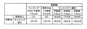
- the number of samples in which the amount of displacement was almost constant in 2 million reciprocating motions among the various types of samples was as shown in FIG. 4 described above.
- the molecules in the table of FIG. 4 indicate the number of samples whose displacement was almost constant. That is, the final flatness of 5 to 6 ⁇ m, more preferably 3 to 4 ⁇ m, is obtained by the lapping and polishing treatment, which is a preferred embodiment of the present invention.
- the durability of the SIDM apparatus 1 can be further improved by polishing the sliding surface 30 until the flatness of the sliding surface 30 becomes 3 to 6 ⁇ m, preferably 3 to 4 ⁇ m. It was. If the flatness after the polishing process is less than 3 ⁇ m, it is considered that the resin J cannot be sufficiently removed, and as a result, the resin J comes into contact with the moving body 5. Further, if the flatness after the polishing treatment exceeds 6 ⁇ m, it becomes larger than the diameter of the fiber bundle, so that it is considered that the fixation of the fiber bundle to the sliding surface 30 becomes insufficient.
- the durability of the SIDM apparatus 1 can be further improved by lapping or cutting so that the planar roughness value Ra of the sliding surface 500 of the moving body 5 is 1 ⁇ m or less.
Landscapes
- Physics & Mathematics (AREA)
- General Physics & Mathematics (AREA)
- Optics & Photonics (AREA)
- General Electrical Machinery Utilizing Piezoelectricity, Electrostriction Or Magnetostriction (AREA)
Abstract
本発明は、従来と比較して耐久性を向上させたSIDM駆動装置の製造方法を提供することを目的とする。この目的は、電圧の印加によって伸縮する圧電素子と、樹脂と繊維束とのコンポジット材料から形成されるとともに、一端に圧電素子が取り付けられ、圧電素子の伸縮によって変位する柱状の駆動軸と、当該圧電素子、または前記駆動軸を支持するベース部材と、駆動軸に対して摩擦係合されて当該駆動軸の軸方向に移動する移動体とを備えるSIDM装置の製造方法において、移動体に対する駆動軸の摺動面で樹脂及び繊維束が同一高さで露出するよう、当該摺動面を平面化するラッピング処理と、摺動面における樹脂のみを除去するよう、当該摺動面を磨く磨き処理と、をこの順に行った後、駆動軸に移動体を摩擦係合させる組立工程を行うことで達成される。
Description
本発明は、リニア圧電アクチュエータの駆動装置の製造方法及びこの製造方法で製造された駆動装置に関する。
従来、例えばレーザー光を出射するレーザーモジュールなどの光学装置には、光源から出射した出射光をSHG(Second Harmonic Generation)素子や光ファイバー等の導波路の入射端面に結合させるための複数の光学素子が光軸を揃えて配設されているものがある。
これらの光学素子のうち、高い調芯精度を求められるものには、駆動手段が設けられ、この駆動手段で光学素子をシフトさせることにより、出射光を導波路の入射端面へ精度良く結合させ、また光学素子の温度変化による光学性能の変化などに対しても補正できるようになっている。
近年、このような光学素子の駆動手段として、スムーズインパクト駆動機構(Smooth Impact Drive Mechanism)を備えた駆動装置(以下、SIDM装置とする。但し、「SIDM」はコニカミノルタオプト株式会社の登録商標)が提案されている。
このSIDM装置とは、電圧の印加によって移動体をナノメートルのオーダーで往復運動させるリニア圧電アクチュエータであり、電圧の印加によって伸縮する圧電素子と、圧電素子の伸縮によって変位する駆動軸と、圧電素子または駆動軸を支持する支持部材と、駆動軸に対して摩擦係合されて当該駆動軸の軸方向に移動する移動体等とを備え、圧電素子の急峻な体積変化と、移動体の慣性力及び摩擦力とを利用して、移動体を駆動軸の軸方向に移動させるようになっている。SIDM装置は、リニア圧電アクチュエータの一種であり、本発明に係わる駆動装置の一例として説明するが、本発明は、SIDM装置以外のリニア圧電アクチュエータにも適用可能である。
ところで、上述のようなSIDM装置においては、光学素子の微小な往復移動(例えば±200nm程度)を複数回(例えば200万回)繰り返すと、移動体が動かなくなってしまう場合があり、耐久性が悪い。
このような問題を解決する技術として、駆動軸を高分子材料と繊維束とのコンポジット材料で形成し、当該駆動軸における移動体との摺動面から高分子材料を除去して繊維束を露出させておき、繊維束を移動体に当接させる技術が開発されている(例えば、特許文献1参照)。この特許文献1では、繊維束の露出をバインディングしている高分子材料の表面を微細な砥粒を含んだ研磨剤などで磨くことにより行っている。
しかしながら、上記特許文献1記載の技術を適用したSIDM装置であっても、依然として移動体の動かなくなる場合があり、耐久性が悪い。そして、このような問題は、特に、組み立て後に接着剤硬化のために高温が掛けられるSIDM装置、例えばレーザーモジュール用のSIDM装置では、より顕著となってしまう。高温にさらされると何故耐久性が低下するかは、詳しくは分かっていないが、高温により高分子材料が変質変形し、移動体との摺動面と接触するようになるからと考えられる。
本発明の課題は、従来と比較して耐久性を向上させることのできる駆動装置の製造方法及びこの製造方法で製造された駆動装置を提供することである。
請求項1記載の発明は、
電圧の印加によって伸縮する圧電素子と、
樹脂と繊維束とのコンポジット材料から形成されるとともに、一端に前記圧電素子が取り付けられ、前記圧電素子の伸縮によって変位する柱状の駆動軸と、
前記圧電素子、または前記駆動軸を支持する支持部と、
前記駆動軸に対して摩擦係合されて当該駆動軸の軸方向に移動する移動体とを備える駆動装置の製造方法において、
前記移動体に対する前記駆動軸の摺動面で前記樹脂及び前記繊維束が同一高さで露出するよう、当該摺動面を平面化するラッピング処理と、
前記摺動面における前記樹脂のみを除去するよう、当該摺動面を磨く磨き処理と、
をこの順に行った後、
前記駆動軸に前記移動体を摩擦係合させる組立工程を行うことを特徴とする。
電圧の印加によって伸縮する圧電素子と、
樹脂と繊維束とのコンポジット材料から形成されるとともに、一端に前記圧電素子が取り付けられ、前記圧電素子の伸縮によって変位する柱状の駆動軸と、
前記圧電素子、または前記駆動軸を支持する支持部と、
前記駆動軸に対して摩擦係合されて当該駆動軸の軸方向に移動する移動体とを備える駆動装置の製造方法において、
前記移動体に対する前記駆動軸の摺動面で前記樹脂及び前記繊維束が同一高さで露出するよう、当該摺動面を平面化するラッピング処理と、
前記摺動面における前記樹脂のみを除去するよう、当該摺動面を磨く磨き処理と、
をこの順に行った後、
前記駆動軸に前記移動体を摩擦係合させる組立工程を行うことを特徴とする。
請求項2記載の発明は、請求項1記載の駆動装置の製造方法において、
前記ラッピング処理では、
前記摺動面の平面度が1~2μmとなるまで、当該摺動面を平面化することを特徴とする。
前記ラッピング処理では、
前記摺動面の平面度が1~2μmとなるまで、当該摺動面を平面化することを特徴とする。
請求項3記載の発明は、請求項1または2記載の駆動装置の製造方法において、
前記磨き処理では、
前記摺動面の平面度が3~4μmとなるまで、当該摺動面を磨くことを特徴とする。
前記磨き処理では、
前記摺動面の平面度が3~4μmとなるまで、当該摺動面を磨くことを特徴とする。
請求項4記載の発明は、請求項1~3の何れか一項に記載の駆動装置の製造方法において、
前記組立工程の前に、
前記駆動軸に対する前記移動体の摺動面の平面粗さ値Raが1μm以下となるよう、この摺動面に対してラッピングまたは切削加工を行う移動体平面化処理を行うことを特徴とする。
前記組立工程の前に、
前記駆動軸に対する前記移動体の摺動面の平面粗さ値Raが1μm以下となるよう、この摺動面に対してラッピングまたは切削加工を行う移動体平面化処理を行うことを特徴とする。
請求項5記載の発明は、請求項1~4の何れか一項に記載の駆動装置の製造方法において、
前記駆動軸として、角柱状のものを用いることを特徴とする。
前記駆動軸として、角柱状のものを用いることを特徴とする。
請求項6記載の発明は、請求項1~5の何れか一項に記載の駆動装置の製造方法において、
前記駆動軸の前記繊維束がカーボンファイバーであることを特徴とする。
前記駆動軸の前記繊維束がカーボンファイバーであることを特徴とする。
請求項7記載の発明は、
電圧の印加によって伸縮する圧電素子と、
樹脂と繊維束とのコンポジット材料から形成されるとともに、一端に前記圧電素子が取り付けられ、前記圧電素子の伸縮によって変位する柱状の駆動軸と、
前記圧電素子、または前記駆動軸を支持する支持部と、
前記駆動軸に対して摩擦係合されて当該駆動軸の軸方向に移動する移動体とを備える駆動装置において、
請求項1~6の何れか一項に記載の駆動装置の製造方法によって製造されたことを特徴とする。
電圧の印加によって伸縮する圧電素子と、
樹脂と繊維束とのコンポジット材料から形成されるとともに、一端に前記圧電素子が取り付けられ、前記圧電素子の伸縮によって変位する柱状の駆動軸と、
前記圧電素子、または前記駆動軸を支持する支持部と、
前記駆動軸に対して摩擦係合されて当該駆動軸の軸方向に移動する移動体とを備える駆動装置において、
請求項1~6の何れか一項に記載の駆動装置の製造方法によって製造されたことを特徴とする。
本発明によれば、移動体に対する駆動軸の摺動面で樹脂及び繊維束が同一高さで露出するよう当該摺動面を平面化するラッピング処理と、摺動面における樹脂のみを除去するよう当該摺動面を磨く磨き処理と、をこの順に行うので、移動体に対する駆動軸の摺動面に充分に繊維束を露出させ、かつ、露出した繊維束を同一高さの平面に形成できる。従って、組み立て後に接着剤硬化のために高温にさらされる場合であっても、従来と比較して駆動軸の摺動面を平滑化し、駆動装置の耐久性を向上させることができる。
以下、図面を参照しながら本発明の好ましい実施形態について説明する。
[光源ユニットの説明]
図1は、本実施の形態における光源ユニット100の概略構成を示す概念図である。
[光源ユニットの説明]
図1は、本実施の形態における光源ユニット100の概略構成を示す概念図である。
この図に示すように、光源ユニット100は、パッケージ10の内部に、レーザー光を照射する赤外半導体レーザー11と、赤外半導体レーザー11からのレーザー光を平行光束化する光学素子(コリメータレンズ)12と、光学素子12からの光束を集光する光学素子(集光レンズ)13と、SHG(Second Harmonic Generation)素子としてとしてのPPLN(Periodically Poled Lithium Niobate)導波路14とを、この順に備えている。ここで、図中の網掛け部分は、光束を示している。
なお、本実施の形態においては、光源ユニット100は最大長さが10mm以下となっており、光学素子12,13は最大径が10mm以下、具体的には4mm程度となっている。また、PPLN導波路14には、当該PPLN導波路14を温度制御する温度制御板16が設けられている。光源ユニット100中のこれらの部材については、例えば以下の文献1,2に開示のものを用いることができる。
<文献1>IQEC/CLEO-PR 2005,Tokyo,Japan,July11-15,2005,post-deadline paper PDG-2
「107-mW low-noise green light emission by frequency doubling of reliable 1060-nm DFB semiconductor laser diodes」
<文献2>2006 Electronic Components and Technology Conference 1064-1065P
「Wavelength Matching and Tuning in Green Laser Packaging using Second Harmonic Generation」
以上の光源ユニット100において、光学素子12,13は支持部材17によって支持されており、光学素子12,13と、支持部材17との間には、光学素子12,13を移動させるSIDM装置1A,1Bと、これらSIDM装置1A,1Bを支持するブラケット18とが介在している。
「107-mW low-noise green light emission by frequency doubling of reliable 1060-nm DFB semiconductor laser diodes」
<文献2>2006 Electronic Components and Technology Conference 1064-1065P
「Wavelength Matching and Tuning in Green Laser Packaging using Second Harmonic Generation」
以上の光源ユニット100において、光学素子12,13は支持部材17によって支持されており、光学素子12,13と、支持部材17との間には、光学素子12,13を移動させるSIDM装置1A,1Bと、これらSIDM装置1A,1Bを支持するブラケット18とが介在している。
SIDM装置1A,1Bは、圧電素子を駆動源とする超小型高精度のアクチュエータであり、本実施の形態においては、光学素子12を図中のZ軸方向、光学素子13を図中のY軸方向に移動させることが可能となっている。但し、SIDM装置1Aが光学素子12をY軸方向に移動させ、SIDM装置1Bが光学素子13をZ軸方向に移動させることとしても良いし、SIDM装置1A,1BがZ軸方向,Y軸方向に加え、X軸方向に対しても光学素子12,13を移動させることとしても良い。このSIDM装置1A,1Bについては、詳細を後述する。
以上のSIDM装置1A,1Bには、図示しない制御部が接続されている。この制御部は、SIDM装置1A,1Bを駆動して光学素子12,13をそれぞれ移動させることにより、これら光学素子12,13の光軸を赤外半導体レーザー11やPPLN導波路14の入射端面に対して合わせる(調芯する)ことができるようになっている。
なお、以上のような光源ユニット100は、例えば、従来より公知の画像投影装置におけるグリーン光の光源として用いることができる。
続いて、SIDM装置1A,1Bについて詳細に説明する。
図2は、本発明に係る駆動装置としてのSIDM装置1A,1B(以下、SIDM装置1とする)の概略構成を示す図である。
この図に示すように、SIDM装置1は、圧電素子2と、駆動軸3と、ベース部材4と、移動体5等とを備えている。
このうち、圧電素子2は、電圧の印加により伸縮するものであり、本実施の形態においては、ピエゾ素子となっている。なお、この圧電素子2の伸縮方向は、SIDM装置1AにおいてはZ軸方向、SIDM装置1BにおいてはY軸方向となっている。また、この圧電素子2には、図示しない制御装置から電圧が印加されるようになっている。
また、駆動軸3は柱状の部材、本実施の形態においては四角柱状の部材であり、圧電素子2の一端に固定され、当該圧電素子2の伸縮によって変位するようになっている。駆動軸としては円柱状のものでもよいが、角柱状のほうが精度を出しやすい効果がある。なお、駆動軸3の変位方向は、SIDM装置1AにおいてはZ軸方向、SIDM装置1BにおいてはY軸方向となっている。
また、本実施の形態においては、後述の図3に示すように、駆動軸3は樹脂と繊維束とのコンポジット材料から形成されており、より詳細には、耐熱エポキシ樹脂Jと、直径φ=6μm程度のカーボンファイバー(繊維束)Cとのコンポジット材料から形成されている。
また、ベース部材4は、本発明における支持部であり、圧電素子2の他端に固定され、図1のブランケット18に固定されている。これにより、ベース部材4は、圧電素子2の移動を制限しつつ、当該圧電素子2を伸縮可能に支持するようになっている。すなわち、圧電素子2の変位方向は駆動軸3側のみに制限される。
なお、本実施の形態においては、圧電素子2の他端にベース部材4を直接的に固定しているが、間にスポンジ等の吸収体を介して固定することとしても良い。また、ベース部材4は、圧電素子2の側周面に固定されることとしても良いし、駆動軸3の側周面に固定されることとしても良い。ベース部材4が駆動軸3の側周面に固定される場合には、当該ベース部材4は、駆動軸3を介して圧電素子2を支持することとなる。この場合、圧電素子2は宙釣り状態となるが、電圧印加により振動し、その振動を駆動軸3に伝達することができる。
また、移動体5は、駆動軸3に対して軸方向に摺動するものであり、駆動軸3に摩擦係合されている。この移動体5は、移動体本体50と、付勢部材6とを有している。
移動体本体50は、駆動軸3の軸方向に延在する溝部51の設けられた略凹字状の部材であり、溝部51の内側面52で駆動軸3の4つの側周面3a~3dのうち、2つの側面3a,3bに当接するようになっている。この移動体本体50における溝部51の外側面53には、付勢部材6と係合する2つの係合爪50b,50cが設けられている。なお、本実施の形態においては、移動体本体50は、亜鉛またはSUSから形成されている。
また、この移動体本体50には、鏡筒102を介して光学素子12(または13)が固定されており、この光学素子12(または13)の光軸方向は、SIDM装置1A,1Bの何れにおいてもX軸方向となっている。但し、図2では、図示の簡略化のため、SIDM装置1Aに支持された光学素子12のみを図示しており、SIDM装置1Bでは、移動体本体50に対する鏡筒102及び光学素子13の固定位置がSIDM装置1Aとは異なっている。
付勢部材6は、駆動軸3を溝部51の内側面52に付勢するものであり、板ばね61と、コイルばね62とを有している。
板ばね61は、略コ字状の板ばねであり、両端部に2つの孔部61b,61cを有している。この板ばね61は、孔部61b,61cを移動体本体50の係合爪50b,50cに係合させることにより、溝部51を跨いで当該溝部51の外側面53に固定されている。
板ばね61の中央部付近は内側にくぼんでおり、このくぼみ部が摺動板61aに当接し、摺動板61aを介して駆動軸3を溝部51の内側面52に付勢するようになっている。この摺動板61aはSUSから形成されている。なお、この板バネ61による付勢方向は、SIDM装置1AではY軸方向、SIDM装置1BではX方向となっている。
コイルばね62は、溝部51の内側に配設されており、SUSからなる摺動板62aを介して駆動軸3を溝部51の内側面52に付勢するようになっている。なお、このコイルばね62による付勢方向は、SIDM装置1AではX方向、SIDM装置1BではZ方向となっている。この摺動板61a、62aは省略することも可能である。
続いて、SIDM装置1の動作について説明する。
SIDM装置1を駆動するには、圧電素子2に対し、緩やかに立上って急速に立下る鋸歯状波駆動パルスを印加する。
これにより、駆動パルスの緩やかな立上り時には、圧電素子2が緩やかに伸長し、駆動軸3がZ軸(またはY軸)の正方向(図2(b)の右から左へ向かう方向)に緩やかに変位する結果、移動体5は駆動軸3に対する摩擦係合力により駆動軸3とともにZ軸(またはY軸)の正方向に移動する。
一方、駆動パルスの急速な立下り時には、圧電素子2が急速に収縮し、駆動軸3がZ軸(またはY軸)方向に沿って急速に変位する結果、移動体5は慣性力により摩擦係合力に打ち勝って実質的にその位置に留まる。
そして、圧電素子2に前記駆動パルスを連続的に印加することにより、駆動軸3に往と復とで速度の異なる往復振動を発生させ、移動体5を連続的にZ軸(またはY軸)の正方向に移動させることができる。
なお、移動体5をZ軸(またはY軸)の負方向(図2(b)の左から右へ向かう方向)に移動させるには、圧電素子2に印加する鋸歯状波駆動パルスの波形を、急速に立上って緩やかに立下る波形とすれば良い。なお、印加される駆動波形としては、ここで示した鋸歯状駆動パルスに限らず、駆動に適したduty比をもつ矩形波や、その他の駆動に適した立ち上がり/立下り特性を持つ波形を適用することも可能である。
続いて、SIDM装置1の製造方法ついて説明する。
図3は、移動体5に対する駆動軸3の摺動面30(図2参照)の微細構造を示す概念図である。
まず、耐熱エポキシ樹脂JとカーボンファイバーCとのコンポジット材料から板状部材を形成した後、当該板状部材から駆動軸3を切り出す。このとき、駆動軸3の表面は、図3(a)に示すような状態となっている。
次に、図3(b)に示すように、駆動軸3の摺動面30における樹脂J及びカーボンファイバーCが同一高さの平面となるよう、当該摺動面30を平面化する(ラッピング処理)。より詳細には、このラッピング処理では、摺動面30の平面度が1~2μmとなるまで、当該摺動面30を平面化する。なお、本実施の形態においては、駆動軸3の側周面全体にラッピング処理を行っている。また、このようなラッピング処理には、市販のラッピングフィルムシート、例えば、粒度が3μm、砥粒が酸化アルミニウムのものを用いることができる。
ここで、本実施の形態において、平面度とは、最大高低差の値であり、より具体的には、もっとも突出した部分と、最も窪んだ部分との高低差の値である。すなわち、平面度が1~2μmとなるまでラッピング処理を行うと、樹脂JとカーボンファイバーCの両者が削られ、その最大高低差が1~2μmと、ほぼ同一高さの平面となる。
次に、図3(c)に示すように、摺動面30における樹脂Jのみを除去するよう当該摺動面30を磨く(磨き処理)。より詳細には、この磨き処理では、摺動面30の平面度が3~4μmとなるまで、当該摺動面30を磨く。この磨き処理で樹脂Jのみを磨き取るので、摺動面30にはラッピング処理で平面とされたカーボンファイバーCのみが露出する。このような磨き処理は、カーボンファイバーCより硬度が低く、樹脂Jよりは硬度が高い材料で行うことができる。
なお、本実施の形態においては、駆動軸3の側周面全体に磨き処理を行っている。また、このような磨き処理では、駆動軸3を狭持して研磨するローラ状の研磨装置を用いることができる。
次に、亜鉛またはSUSからダイキャストによって移動体5を形成した後、駆動軸3に対する移動体5の摺動面500(図2参照)の平面粗さ値Raが1μm以下となるよう、この摺動面500に対してラッピングまたは切削加工を行う(移動体平面化処理)。
なお、この移動体平面化処理において、ラッピングには例えば「2000番」のヤスリ(研磨紙)を用いることができ、切削加工にはフライス工具を用いることができる。但し、移動体5がダイキャストによって形成されていない場合、例えば削り出し加工によって形成されている場合には、加工により充分に平滑化できるので、この移動体平面化処理は行わなくても良い。
次に、駆動軸3に対する摺動板61a,62aの摺動面の平面度が1μm以下となるよう、当該摺動面に鏡面仕上げを行う。
そして、駆動軸3に移動体5を摩擦係合させ、SIDM装置1を組み立てた後(組立工程)、120℃、1時間の加熱を4回以上繰り返して各部材間の接着剤を硬化させることにより、SIDM装置1が製造される。
以上のSIDM装置1の製造方法によれば、移動体5に対する駆動軸3の摺動面30で樹脂J及びカーボンファイバーCが同一高さで露出するよう当該摺動面30を平面化するラッピング処理と、摺動面30における樹脂Jのみを除去するよう当該摺動面30を磨く磨き処理と、をこの順に行うので、移動体5に対する駆動軸3の摺動面30に充分にカーボンファイバーCを露出させ、かつ、これらカーボンファイバーCを同一平面とした状態の摺動面30を作成することができる。従って、接着剤硬化のために組み立て後に高温にさらされる場合であっても、高温により変質変形した樹脂がカーボンファイバCの最上面まで到達することは無く、従来と比較してSIDM装置1の耐久性を向上させることができる。
また、ラッピング処理では、摺動面30の平面度が1~2μmとなるまで当該摺動面30を平面化し、磨き処理では、摺動面30の平面度が3~4μmとなるまで当該摺動面30を磨くので、駆動軸3の摺動面30をカーボンファイバーCのみが露出した平滑面とすることができる。従って、SIDM装置1の耐久性を更に向上させることができる。
また、移動体5の摺動面500の平面粗さ値Raが1μm以下となるよう、この摺動面500に対してラッピングまたは切削加工を行うので、駆動軸3に対する移動体5の摺動面500を平滑化することができる。従って、SIDM装置1の耐久性を更に向上させることができる。
また、摺動板61a,62aの摺動面の平面度が1μm以下となるよう、当該摺動面に鏡面仕上げを行うので、駆動軸3に対する摺動板61a,62aの摺動面を平滑化することができる。従って、SIDM装置1の耐久性を更に向上させることができる。
なお、本発明は上記実施の形態に限定して解釈されるべきではなく、適宜変更・改良が可能であることはもちろんである。
以下、実施例および比較例を挙げることにより、本発明に係る駆動装置をさらに具体的に説明する。但し、本発明は実施例に限定されるものではない。
[サンプルの作製]
本発明に係る駆動装置の実施例,比較例のサンプルとして、図4に示すような10種類のSIDM装置1をそれぞれ6個作製した。なお、図中、カッコ内の数値は、サンプル番号を示している。また、以下のサンプル(1)~(10)において、サンプル(1)~(4)、および(5)(9)(10)は本発明の比較例に相当し、サンプル(6)(7)(8)は本発明の実施例に相当する。
[サンプルの作製]
本発明に係る駆動装置の実施例,比較例のサンプルとして、図4に示すような10種類のSIDM装置1をそれぞれ6個作製した。なお、図中、カッコ内の数値は、サンプル番号を示している。また、以下のサンプル(1)~(10)において、サンプル(1)~(4)、および(5)(9)(10)は本発明の比較例に相当し、サンプル(6)(7)(8)は本発明の実施例に相当する。
ここで、サンプル(1)のSIDM装置1では、駆動軸3として、耐熱エポキシ樹脂とカーボンファイバー(繊維束)とのコンポジット材料の板状部材から切り出された後、摺動面30の平面度が1~2μmとなるまでラッピング処理されたものを使用し、移動体5として、亜鉛からダイキャストによって形成されたものをそのまま使用した。
また、サンプル(2)のSIDM装置1では、駆動軸3として、耐熱エポキシ樹脂とカーボンファイバー(繊維束)とのコンポジット材料の板状部材から切り出された後、摺動面30の平面度が1~2μmとなるまでラッピング処理されたものを使用し、移動体5として、亜鉛からダイキャストによって形成された後、平面粗さ値Raが1μm以下となるようラッピングされたものを使用した。
また、サンプル(3)のSIDM装置1では、駆動軸3として、耐熱エポキシ樹脂とカーボンファイバー(繊維束)とのコンポジット材料の板状部材から切り出された後、摺動面30の平面度が3~4μmとなるまで磨き処理されたものを使用し、移動体5として、亜鉛からダイキャストによって形成されたものをそのまま使用した。
また、サンプル(4)のSIDM装置1では、駆動軸3として、耐熱エポキシ樹脂とカーボンファイバー(繊維束)とのコンポジット材料の板状部材から切り出された後、摺動面30の平面度が3~4μmとなるまで磨き処理されたものを使用し、移動体5として、亜鉛からダイキャストによって形成された後、平面粗さ値Raが1μm以下となるようラッピングされたものを使用した。
また、サンプル(5)のSIDM装置1では、駆動軸3として、耐熱エポキシ樹脂とカーボンファイバー(繊維束)とのコンポジット材料の板状部材から切り出され、摺動面30の平面度が1~2μmとなるまでラッピング処理された後、摺動面30の平面度が5~6μmとなるまで磨き処理されたものを使用した。また、移動体5として、亜鉛からダイキャストによって形成されたものをそのまま使用した。
また、サンプル(6)のSIDM装置1では、駆動軸3として、耐熱エポキシ樹脂とカーボンファイバー(繊維束)とのコンポジット材料の板状部材から切り出され、摺動面30の平面度が1~2μmとなるまでラッピング処理された後、摺動面30の平面度が5~6μmとなるまで磨き処理されたものを使用した。また、移動体5として、亜鉛からダイキャストによって形成された後、平面粗さ値Raが1μm以下となるようラッピングされたものを使用した。
また、サンプル(7)のSIDM装置1では、駆動軸3として、耐熱エポキシ樹脂とカーボンファイバー(繊維束)とのコンポジット材料の板状部材から切り出され、摺動面30の平面度が1~2μmとなるまでラッピング処理された後、摺動面30の平面度が3~4μmとなるまで磨き処理されたものを使用した。また、移動体5として、亜鉛からダイキャストによって形成されたものをそのまま使用した。
また、サンプル(8)のSIDM装置1では、駆動軸3として、耐熱エポキシ樹脂とカーボンファイバー(繊維束)とのコンポジット材料の板状部材から切り出され、摺動面30の平面度が1~2μmとなるまでラッピング処理された後、摺動面30の平面度が3~4μmとなるまで磨き処理されたものを使用した。また、移動体5として、亜鉛からダイキャストによって形成された後、平面粗さ値Raが1μm以下となるようラッピングされたものを使用した。
また、サンプル(9)のSIDM装置1では、駆動軸3として、耐熱エポキシ樹脂とカーボンファイバー(繊維束)とのコンポジット材料の板状部材から切り出され、摺動面30の平面度が1~2μmとなるまでラッピング処理された後、摺動面30の平面度が1~2μmとなるまで磨き処理されたものを使用した。また、移動体5として、亜鉛からダイキャストによって形成されたものをそのまま使用した。
また、サンプル(10)のSIDM装置1では、駆動軸3として、耐熱エポキシ樹脂とカーボンファイバー(繊維束)とのコンポジット材料の板状部材から切り出され、摺動面30の平面度が1~2μmとなるまでラッピング処理された後、摺動面30の平面度が1~2μmとなるまで磨き処理されたものを使用した。また、移動体5として、亜鉛からダイキャストによって形成された後、平面粗さ値Raが1μm以下となるようラッピングされたものを使用した。
[サンプルの耐久性評価]
作製された各サンプルについて、200nmの微小な往復動作を200万回、移動体5に行わせ、各動作での変位量を計測したところ、図5(a),(b)に示すように、計測の最後まで変位量がほぼ一定だったサンプル(図5(a))と、計測途中で変位量が0になったサンプル(図5(b))とがあった。
[サンプルの耐久性評価]
作製された各サンプルについて、200nmの微小な往復動作を200万回、移動体5に行わせ、各動作での変位量を計測したところ、図5(a),(b)に示すように、計測の最後まで変位量がほぼ一定だったサンプル(図5(a))と、計測途中で変位量が0になったサンプル(図5(b))とがあった。
この結果に基づいて、各種類のサンプルのうち、200万回の往復動作で変位量がほぼ一定だったサンプルの個数をカウントしたところ、上述の図4に示した通りとなった。図4の表中の分子が変位量がほぼ一定だったサンプルの個数を示す。すなわち、ラッピングと磨き処理とで最終的に平面度5~6μm、より好ましくは3~4μmとしたものが本発明の好適な実施例である。
なお、上述のサンプル(2)、(4)、(6)、(8)、(10)において、移動体5の摺動面500に対し、ラッピングの代わりに切削処理を行って平面粗さ値Raを1μm以下とした場合にも、同様の結果が得られた。また、図4中のサンプル(1),(3)について「-」と記載されているのは、実験開始当初から往復動作の挙動がおかしく評価可能なデータが得られなかったことを示している。
以上の結果から、移動体5に対してラッピング処理と磨き処理とをこの順に行うことにより、SIDM装置1の耐久性を向上させられることが分かった。
また、磨き処理では、摺動面30の平面度が3~6μm、好ましくは3~4μmとなるまで当該摺動面30を磨くことにより、SIDM装置1の耐久性を更に向上させられることが分かった。磨き処理後の平面度が3μm未満であると、充分に樹脂Jを除去できない結果、樹脂Jが移動体5に当接してしまうからであると考えられる。また、磨き処理後の平面度が6μmを越えると、繊維束の直径より大きくなるので繊維束の摺動面30への固定が不十分となると考えられる。
また、移動体5の摺動面500の平面粗さ値Raが1μm以下となるようラッピングまたは切削加工を行うことにより、SIDM装置1の耐久性を更に向上させられることが分かった。
1,1A,1B SIDM装置(駆動装置)
2 圧電素子
3 駆動軸
4 ベース部材(移動制限部)
5 移動体
J 樹脂
C カーボンファイバー(繊維束)
2 圧電素子
3 駆動軸
4 ベース部材(移動制限部)
5 移動体
J 樹脂
C カーボンファイバー(繊維束)
Claims (7)
- 電圧の印加によって伸縮する圧電素子と、
樹脂と繊維束とのコンポジット材料から形成されるとともに、一端に前記圧電素子が取り付けられ、前記圧電素子の伸縮によって変位する柱状の駆動軸と、
前記圧電素子を、または前記駆動軸支持する支持部と、
前記駆動軸に対して摩擦係合されて当該駆動軸の軸方向に移動する移動体とを備える駆動装置の製造方法において、
前記移動体に対する前記駆動軸の摺動面で前記樹脂及び前記繊維束が同一高さで露出するよう、当該摺動面を平面化するラッピング処理と、
前記摺動面における前記樹脂のみを除去するよう、当該摺動面を磨く磨き処理と、
をこの順に行った後、
前記駆動軸に前記移動体を摩擦係合させる組立工程を行うことを特徴とする駆動装置の製造方法。 - 請求項1記載の駆動装置の製造方法において、
前記ラッピング処理では、
前記摺動面の平面度が1~2μmとなるまで、当該摺動面を平面化することを特徴とする駆動装置の製造方法。 - 請求項1または2記載の駆動装置の製造方法において、
前記磨き処理では、
前記摺動面の平面度が3~4μmとなるまで、当該摺動面を磨くことを特徴とする駆動装置の製造方法。 - 請求項1~3の何れか一項に記載の駆動装置の製造方法において、
前記組立工程の前に、
前記駆動軸に対する前記移動体の摺動面の平面粗さ値Raが1μm以下となるよう、この摺動面に対してラッピングまたは切削加工を行う移動体平面化処理を行うことを特徴とする駆動装置の製造方法。 - 請求項1~4の何れか一項に記載の駆動装置の製造方法において、
前記駆動軸として、角柱状のものを用いることを特徴とする駆動装置の製造方法。 - 請求項1~5の何れか一項に記載の駆動装置の製造方法において、
前記駆動軸の前記繊維束がカーボンファイバーであることを特徴とする駆動装置の製造方法。 - 電圧の印加によって伸縮する圧電素子と、
樹脂と繊維束とのコンポジット材料から形成されるとともに、一端に前記圧電素子が取り付けられ、前記圧電素子の伸縮によって変位する柱状の駆動軸と、
前記圧電素子、または前記駆動軸を支持する支持部と、
前記駆動軸に対して摩擦係合されて当該駆動軸の軸方向に移動する移動体とを備える駆動装置において、
請求項1~6の何れか一項に記載の駆動装置の製造方法によって製造されたことを特徴とする駆動装置。
Priority Applications (1)
| Application Number | Priority Date | Filing Date | Title |
|---|---|---|---|
| JP2011505925A JPWO2010109968A1 (ja) | 2009-03-24 | 2010-02-12 | 駆動装置の製造方法及びこの製造方法で製造された駆動装置 |
Applications Claiming Priority (2)
| Application Number | Priority Date | Filing Date | Title |
|---|---|---|---|
| JP2009071664 | 2009-03-24 | ||
| JP2009-071664 | 2009-03-24 |
Publications (1)
| Publication Number | Publication Date |
|---|---|
| WO2010109968A1 true WO2010109968A1 (ja) | 2010-09-30 |
Family
ID=42780664
Family Applications (1)
| Application Number | Title | Priority Date | Filing Date |
|---|---|---|---|
| PCT/JP2010/052050 Ceased WO2010109968A1 (ja) | 2009-03-24 | 2010-02-12 | 駆動装置の製造方法及びこの製造方法で製造された駆動装置 |
Country Status (2)
| Country | Link |
|---|---|
| JP (1) | JPWO2010109968A1 (ja) |
| WO (1) | WO2010109968A1 (ja) |
Citations (3)
| Publication number | Priority date | Publication date | Assignee | Title |
|---|---|---|---|---|
| JPH06209585A (ja) * | 1992-12-04 | 1994-07-26 | Olympus Optical Co Ltd | 摺動材料 |
| JPH1042579A (ja) * | 1996-07-23 | 1998-02-13 | Canon Inc | 振動波モータ |
| JP2004297921A (ja) * | 2003-03-27 | 2004-10-21 | Minolta Co Ltd | 電気機械変換素子を用いた駆動装置 |
-
2010
- 2010-02-12 JP JP2011505925A patent/JPWO2010109968A1/ja active Pending
- 2010-02-12 WO PCT/JP2010/052050 patent/WO2010109968A1/ja not_active Ceased
Patent Citations (3)
| Publication number | Priority date | Publication date | Assignee | Title |
|---|---|---|---|---|
| JPH06209585A (ja) * | 1992-12-04 | 1994-07-26 | Olympus Optical Co Ltd | 摺動材料 |
| JPH1042579A (ja) * | 1996-07-23 | 1998-02-13 | Canon Inc | 振動波モータ |
| JP2004297921A (ja) * | 2003-03-27 | 2004-10-21 | Minolta Co Ltd | 電気機械変換素子を用いた駆動装置 |
Also Published As
| Publication number | Publication date |
|---|---|
| JPWO2010109968A1 (ja) | 2012-09-27 |
Similar Documents
| Publication | Publication Date | Title |
|---|---|---|
| US11303228B2 (en) | Driving device, optical device, and image pickup device | |
| US7199506B2 (en) | Piezoelectric actuator for driving lens | |
| JP5683643B2 (ja) | リニア超音波モータ及びそれを有する光学装置 | |
| US8445837B2 (en) | Vibration actuator for rotating a rotating axle and image capturing apparatus | |
| JP2017173502A (ja) | レンズ鏡筒及び撮像装置 | |
| JP7046614B2 (ja) | 振動型アクチュエータ及び電子機器 | |
| US11437933B2 (en) | Vibration wave motor and electronic apparatus having an electrical-mechanical energy conversion element | |
| JP2006330054A (ja) | レンズ鏡胴 | |
| JP2012029495A (ja) | 駆動装置 | |
| JP2007049879A (ja) | アクチュエータ | |
| WO2010109968A1 (ja) | 駆動装置の製造方法及びこの製造方法で製造された駆動装置 | |
| US10439518B2 (en) | Vibration-type actuator, driving method for vibration-type actuator, and electronic apparatus equipped with vibration-type actuator | |
| JP6659164B2 (ja) | リニア駆動装置、レンズ鏡筒及び撮像装置 | |
| JP6812510B2 (ja) | 振動型アクチュエータ及びそれを有する電子機器 | |
| JP6708472B2 (ja) | 振動波モータ及び振動波モータが搭載された光学機器 | |
| JP7346264B2 (ja) | 振動型アクチュエータ及びその駆動方法 | |
| JP5233845B2 (ja) | 駆動装置 | |
| CN107342705B (zh) | 马达和包括马达的电子设备 | |
| JP5045187B2 (ja) | 光学素子ユニット | |
| JP2018101094A (ja) | 振動型アクチュエータ、レンズ駆動装置、光学機器及び電子機器 | |
| US20250314851A1 (en) | Vibration type actuator, lens barrel, image capturing apparatus, and stage apparatus | |
| JP2017200355A (ja) | 振動波モータおよび振動波モータが搭載された電子機器 | |
| JPWO2010110063A1 (ja) | 駆動装置 | |
| JP6537482B2 (ja) | 振動波モータおよび電子機器 | |
| JP2018137859A (ja) | 振動波モータ及び振動波モータを有する光学装置 |
Legal Events
| Date | Code | Title | Description |
|---|---|---|---|
| 121 | Ep: the epo has been informed by wipo that ep was designated in this application |
Ref document number: 10755769 Country of ref document: EP Kind code of ref document: A1 |
|
| WWE | Wipo information: entry into national phase |
Ref document number: 2011505925 Country of ref document: JP |
|
| NENP | Non-entry into the national phase |
Ref country code: DE |
|
| 122 | Ep: pct application non-entry in european phase |
Ref document number: 10755769 Country of ref document: EP Kind code of ref document: A1 |