WO2010109722A1 - 非水電解質二次電池用負極材料、非水電解質二次電池用負極材料の製造方法、非水電解質二次電池および電池パック - Google Patents
非水電解質二次電池用負極材料、非水電解質二次電池用負極材料の製造方法、非水電解質二次電池および電池パック Download PDFInfo
- Publication number
- WO2010109722A1 WO2010109722A1 PCT/JP2009/069504 JP2009069504W WO2010109722A1 WO 2010109722 A1 WO2010109722 A1 WO 2010109722A1 JP 2009069504 W JP2009069504 W JP 2009069504W WO 2010109722 A1 WO2010109722 A1 WO 2010109722A1
- Authority
- WO
- WIPO (PCT)
- Prior art keywords
- negative electrode
- electrolyte secondary
- secondary battery
- lithium
- titanium
- Prior art date
- Legal status (The legal status is an assumption and is not a legal conclusion. Google has not performed a legal analysis and makes no representation as to the accuracy of the status listed.)
- Ceased
Links
Images




Classifications
-
- H—ELECTRICITY
- H01—ELECTRIC ELEMENTS
- H01M—PROCESSES OR MEANS, e.g. BATTERIES, FOR THE DIRECT CONVERSION OF CHEMICAL ENERGY INTO ELECTRICAL ENERGY
- H01M6/00—Primary cells; Manufacture thereof
- H01M6/42—Grouping of primary cells into batteries
- H01M6/46—Grouping of primary cells into batteries of flat cells
-
- B—PERFORMING OPERATIONS; TRANSPORTING
- B82—NANOTECHNOLOGY
- B82Y—SPECIFIC USES OR APPLICATIONS OF NANOSTRUCTURES; MEASUREMENT OR ANALYSIS OF NANOSTRUCTURES; MANUFACTURE OR TREATMENT OF NANOSTRUCTURES
- B82Y30/00—Nanotechnology for materials or surface science, e.g. nanocomposites
-
- C—CHEMISTRY; METALLURGY
- C01—INORGANIC CHEMISTRY
- C01G—COMPOUNDS CONTAINING METALS NOT COVERED BY SUBCLASSES C01D OR C01F
- C01G23/00—Compounds of titanium
- C01G23/003—Titanates
- C01G23/005—Alkali titanates
-
- H—ELECTRICITY
- H01—ELECTRIC ELEMENTS
- H01M—PROCESSES OR MEANS, e.g. BATTERIES, FOR THE DIRECT CONVERSION OF CHEMICAL ENERGY INTO ELECTRICAL ENERGY
- H01M10/00—Secondary cells; Manufacture thereof
- H01M10/05—Accumulators with non-aqueous electrolyte
- H01M10/052—Li-accumulators
- H01M10/0525—Rocking-chair batteries, i.e. batteries with lithium insertion or intercalation in both electrodes; Lithium-ion batteries
-
- H—ELECTRICITY
- H01—ELECTRIC ELEMENTS
- H01M—PROCESSES OR MEANS, e.g. BATTERIES, FOR THE DIRECT CONVERSION OF CHEMICAL ENERGY INTO ELECTRICAL ENERGY
- H01M10/00—Secondary cells; Manufacture thereof
- H01M10/42—Methods or arrangements for servicing or maintenance of secondary cells or secondary half-cells
- H01M10/425—Structural combination with electronic components, e.g. electronic circuits integrated to the outside of the casing
-
- H—ELECTRICITY
- H01—ELECTRIC ELEMENTS
- H01M—PROCESSES OR MEANS, e.g. BATTERIES, FOR THE DIRECT CONVERSION OF CHEMICAL ENERGY INTO ELECTRICAL ENERGY
- H01M4/00—Electrodes
- H01M4/02—Electrodes composed of, or comprising, active material
- H01M4/13—Electrodes for accumulators with non-aqueous electrolyte, e.g. for lithium-accumulators; Processes of manufacture thereof
- H01M4/131—Electrodes based on mixed oxides or hydroxides, or on mixtures of oxides or hydroxides, e.g. LiCoOx
-
- H—ELECTRICITY
- H01—ELECTRIC ELEMENTS
- H01M—PROCESSES OR MEANS, e.g. BATTERIES, FOR THE DIRECT CONVERSION OF CHEMICAL ENERGY INTO ELECTRICAL ENERGY
- H01M4/00—Electrodes
- H01M4/02—Electrodes composed of, or comprising, active material
- H01M4/36—Selection of substances as active materials, active masses, active liquids
- H01M4/48—Selection of substances as active materials, active masses, active liquids of inorganic oxides or hydroxides
- H01M4/485—Selection of substances as active materials, active masses, active liquids of inorganic oxides or hydroxides of mixed oxides or hydroxides for inserting or intercalating light metals, e.g. LiTi2O4 or LiTi2OxFy
-
- H—ELECTRICITY
- H01—ELECTRIC ELEMENTS
- H01M—PROCESSES OR MEANS, e.g. BATTERIES, FOR THE DIRECT CONVERSION OF CHEMICAL ENERGY INTO ELECTRICAL ENERGY
- H01M4/00—Electrodes
- H01M4/02—Electrodes composed of, or comprising, active material
- H01M4/62—Selection of inactive substances as ingredients for active masses, e.g. binders, fillers
- H01M4/624—Electric conductive fillers
-
- H—ELECTRICITY
- H01—ELECTRIC ELEMENTS
- H01M—PROCESSES OR MEANS, e.g. BATTERIES, FOR THE DIRECT CONVERSION OF CHEMICAL ENERGY INTO ELECTRICAL ENERGY
- H01M4/00—Electrodes
- H01M4/02—Electrodes composed of, or comprising, active material
- H01M4/62—Selection of inactive substances as ingredients for active masses, e.g. binders, fillers
- H01M4/624—Electric conductive fillers
- H01M4/625—Carbon or graphite
-
- H—ELECTRICITY
- H01—ELECTRIC ELEMENTS
- H01M—PROCESSES OR MEANS, e.g. BATTERIES, FOR THE DIRECT CONVERSION OF CHEMICAL ENERGY INTO ELECTRICAL ENERGY
- H01M4/00—Electrodes
- H01M4/02—Electrodes composed of, or comprising, active material
- H01M4/62—Selection of inactive substances as ingredients for active masses, e.g. binders, fillers
- H01M4/624—Electric conductive fillers
- H01M4/626—Metals
-
- C—CHEMISTRY; METALLURGY
- C01—INORGANIC CHEMISTRY
- C01P—INDEXING SCHEME RELATING TO STRUCTURAL AND PHYSICAL ASPECTS OF SOLID INORGANIC COMPOUNDS
- C01P2002/00—Crystal-structural characteristics
- C01P2002/70—Crystal-structural characteristics defined by measured X-ray, neutron or electron diffraction data
- C01P2002/72—Crystal-structural characteristics defined by measured X-ray, neutron or electron diffraction data by d-values or two theta-values, e.g. as X-ray diagram
-
- C—CHEMISTRY; METALLURGY
- C01—INORGANIC CHEMISTRY
- C01P—INDEXING SCHEME RELATING TO STRUCTURAL AND PHYSICAL ASPECTS OF SOLID INORGANIC COMPOUNDS
- C01P2004/00—Particle morphology
- C01P2004/54—Particles characterised by their aspect ratio, i.e. the ratio of sizes in the longest to the shortest dimension
-
- C—CHEMISTRY; METALLURGY
- C01—INORGANIC CHEMISTRY
- C01P—INDEXING SCHEME RELATING TO STRUCTURAL AND PHYSICAL ASPECTS OF SOLID INORGANIC COMPOUNDS
- C01P2004/00—Particle morphology
- C01P2004/60—Particles characterised by their size
- C01P2004/64—Nanometer sized, i.e. from 1-100 nanometer
-
- C—CHEMISTRY; METALLURGY
- C01—INORGANIC CHEMISTRY
- C01P—INDEXING SCHEME RELATING TO STRUCTURAL AND PHYSICAL ASPECTS OF SOLID INORGANIC COMPOUNDS
- C01P2006/00—Physical properties of inorganic compounds
- C01P2006/11—Powder tap density
-
- C—CHEMISTRY; METALLURGY
- C01—INORGANIC CHEMISTRY
- C01P—INDEXING SCHEME RELATING TO STRUCTURAL AND PHYSICAL ASPECTS OF SOLID INORGANIC COMPOUNDS
- C01P2006/00—Physical properties of inorganic compounds
- C01P2006/12—Surface area
-
- C—CHEMISTRY; METALLURGY
- C01—INORGANIC CHEMISTRY
- C01P—INDEXING SCHEME RELATING TO STRUCTURAL AND PHYSICAL ASPECTS OF SOLID INORGANIC COMPOUNDS
- C01P2006/00—Physical properties of inorganic compounds
- C01P2006/40—Electric properties
-
- H—ELECTRICITY
- H01—ELECTRIC ELEMENTS
- H01M—PROCESSES OR MEANS, e.g. BATTERIES, FOR THE DIRECT CONVERSION OF CHEMICAL ENERGY INTO ELECTRICAL ENERGY
- H01M4/00—Electrodes
- H01M4/02—Electrodes composed of, or comprising, active material
- H01M2004/021—Physical characteristics, e.g. porosity, surface area
-
- H—ELECTRICITY
- H01—ELECTRIC ELEMENTS
- H01M—PROCESSES OR MEANS, e.g. BATTERIES, FOR THE DIRECT CONVERSION OF CHEMICAL ENERGY INTO ELECTRICAL ENERGY
- H01M4/00—Electrodes
- H01M4/02—Electrodes composed of, or comprising, active material
- H01M2004/026—Electrodes composed of, or comprising, active material characterised by the polarity
- H01M2004/027—Negative electrodes
-
- H—ELECTRICITY
- H01—ELECTRIC ELEMENTS
- H01M—PROCESSES OR MEANS, e.g. BATTERIES, FOR THE DIRECT CONVERSION OF CHEMICAL ENERGY INTO ELECTRICAL ENERGY
- H01M2200/00—Safety devices for primary or secondary batteries
- H01M2200/10—Temperature sensitive devices
-
- H—ELECTRICITY
- H01—ELECTRIC ELEMENTS
- H01M—PROCESSES OR MEANS, e.g. BATTERIES, FOR THE DIRECT CONVERSION OF CHEMICAL ENERGY INTO ELECTRICAL ENERGY
- H01M4/00—Electrodes
- H01M4/02—Electrodes composed of, or comprising, active material
- H01M4/04—Processes of manufacture in general
- H01M4/0402—Methods of deposition of the material
- H01M4/0404—Methods of deposition of the material by coating on electrode collectors
-
- H—ELECTRICITY
- H01—ELECTRIC ELEMENTS
- H01M—PROCESSES OR MEANS, e.g. BATTERIES, FOR THE DIRECT CONVERSION OF CHEMICAL ENERGY INTO ELECTRICAL ENERGY
- H01M4/00—Electrodes
- H01M4/02—Electrodes composed of, or comprising, active material
- H01M4/04—Processes of manufacture in general
- H01M4/0438—Processes of manufacture in general by electrochemical processing
-
- H—ELECTRICITY
- H01—ELECTRIC ELEMENTS
- H01M—PROCESSES OR MEANS, e.g. BATTERIES, FOR THE DIRECT CONVERSION OF CHEMICAL ENERGY INTO ELECTRICAL ENERGY
- H01M4/00—Electrodes
- H01M4/02—Electrodes composed of, or comprising, active material
- H01M4/13—Electrodes for accumulators with non-aqueous electrolyte, e.g. for lithium-accumulators; Processes of manufacture thereof
- H01M4/139—Processes of manufacture
- H01M4/1391—Processes of manufacture of electrodes based on mixed oxides or hydroxides, or on mixtures of oxides or hydroxides, e.g. LiCoOx
-
- Y—GENERAL TAGGING OF NEW TECHNOLOGICAL DEVELOPMENTS; GENERAL TAGGING OF CROSS-SECTIONAL TECHNOLOGIES SPANNING OVER SEVERAL SECTIONS OF THE IPC; TECHNICAL SUBJECTS COVERED BY FORMER USPC CROSS-REFERENCE ART COLLECTIONS [XRACs] AND DIGESTS
- Y02—TECHNOLOGIES OR APPLICATIONS FOR MITIGATION OR ADAPTATION AGAINST CLIMATE CHANGE
- Y02E—REDUCTION OF GREENHOUSE GAS [GHG] EMISSIONS, RELATED TO ENERGY GENERATION, TRANSMISSION OR DISTRIBUTION
- Y02E60/00—Enabling technologies; Technologies with a potential or indirect contribution to GHG emissions mitigation
- Y02E60/10—Energy storage using batteries
Definitions
- the present invention relates to a negative electrode material for a nonaqueous electrolyte secondary battery, a method for producing a negative electrode material for a nonaqueous electrolyte secondary battery, a nonaqueous electrolyte secondary battery, and a battery pack.
- lithium ion secondary batteries that are charged and discharged by moving lithium ions between a negative electrode and a positive electrode have been actively researched and developed as high energy density batteries.
- titanium oxide enables stable rapid charge / discharge from the viewpoint of potential characteristics.
- a negative electrode containing titanium oxide as an active material has a longer life than conventional carbon materials.
- the conventional titanium oxide has a higher potential with respect to metallic lithium and a lower capacity density per weight than a general carbon-based negative electrode. For this reason, there is a problem that the energy density important as a secondary battery is low.
- the electrode potential of titanium oxide is due to the oxidation-reduction reaction between Ti 3+ and Ti 4+ when lithium is electrochemically inserted and desorbed.
- the electrode potential is electrochemically restricted, and therefore it is substantially difficult to lower the electrode potential for the purpose of improving the energy density. Therefore, maximizing the theoretical electrode capacity of titanium oxide has an important role in achieving an improvement in energy density.
- titanium oxide is poor in electronic conductivity in a state where lithium ions are not inserted. Therefore, when used as an active material, it is necessary to use a conductive additive together.
- Japanese Patent Application Laid-Open No. 2007-234358 discloses a technique for filling an active material into the pores of porous particles having micropores.
- the contact area between the active material and the conductive porous particles is increased, and the permeability of the electrolytic solution is also improved.
- the active material filled in the pores of the porous particles is bulky (lumped), the movement distance of lithium ions from the surface to the center becomes long. As a result, it is not suitable for high-speed charge / discharge, and it is difficult to improve the active material capacity to a value approximating its theoretical capacity.
- the present invention provides a negative electrode material for a non-aqueous electrolyte secondary battery that exhibits an electrode potential in the vicinity of 1.5 V equivalent to that of a conventional titanic acid material on a lithium basis and has a higher energy density, and a method for manufacturing the same. Objective.
- An object of the present invention is to provide a nonaqueous electrolyte secondary battery having a negative electrode including the negative electrode material and having a higher energy density, and a battery pack having a plurality of the batteries.
- porous conductive particles and at least one of a nanotube structure and a nanowire structure formed on at least one of the surface of the porous conductive particles and the porous structure there is provided a negative electrode material for a non-aqueous electrolyte secondary battery comprising an active material composed of a lithium titanium composite oxide represented by the general formula Li x TiO 2 (where x is 0 ⁇ x ⁇ 1).
- a dispersion is prepared by dispersing porous conductive particles in a titanium alkoxide solution; Exposing the dispersion under reduced pressure to infiltrate a titanium alkoxide solution into at least one of the surface of the porous conductive particles and the inside of the porous body; Performing a hydrolysis reaction after the wetting to produce gelled titanium-containing porous conductive particles; Firing the gelled titanium-containing porous conductive particles in an inert gas atmosphere to convert at least one of the gelled titanium surface and the porous gelled titanium particles into titanium oxide; After the obtained titanium oxide-containing porous conductive particles are dispersed in an alkaline solution, the titanium oxide-containing porous conductive particles are heated under pressure to change the surface of the porous conductive particles and at least one of the titanium oxides into a nanotube structure and nanostructure.
- a positive electrode capable of inserting and extracting lithium; It has a porous conductive particle and at least one of a nanotube structure and a nanowire structure formed on at least one of the surface of the porous conductive particle and the porous structure, and has a general formula Li x TiO 2 (formula Provided is a non-aqueous electrolyte secondary battery including a negative electrode material including a negative electrode material including an active material composed of a lithium-titanium composite oxide, wherein x is 0 ⁇ x ⁇ 1) .
- a battery pack comprising a plurality of the nonaqueous electrolyte secondary batteries of the third aspect, and these batteries are electrically connected in series, parallel, or series and parallel to each other.
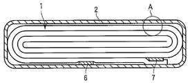
- FIG. 1 is a cross-sectional view of a flat nonaqueous electrolyte secondary battery according to a third embodiment.
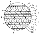
- FIG. 2 is an enlarged cross-sectional view of a part A in FIG.
- FIG. 3 is a partially cutaway perspective view schematically showing another flat type nonaqueous electrolyte secondary battery according to the third embodiment.
- 4 is an enlarged cross-sectional view of a portion B in FIG.
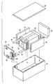
- FIG. 5 is an exploded perspective view of the battery pack according to the fourth embodiment.
- FIG. 6 is a block diagram showing an electric circuit of the battery pack of FIG. FIG.
- FIG. 7 is a powder X-ray diffraction pattern by a Cu—K ⁇ ray of the composite material (negative electrode material) of anatase-type titanium dioxide nanotubes and porous carbon obtained in Synthesis Example 1.
- FIG. 8 is a diagram showing the results of the particle size distribution obtained from the small-angle X-ray scattering measurement of the composite material (negative electrode material) obtained in Synthesis Example 1.
- FIG. 9 is a diagram showing the results of the particle size distribution obtained from the small-angle X-ray scattering measurement of the composite material (negative electrode material) obtained in Synthesis Example 2.
- FIG. 10 is a diagram showing initial charge / discharge curves of the electrochemical measurement cells of Example 1 and Comparative Example 1.
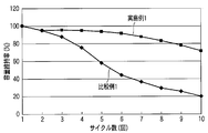
- FIG. FIG. 11 is a diagram showing the repetitive discharge capacity retention rates of the electrochemical measurement cells of Example 1 and Comparative Example 1.
- the negative electrode material for a nonaqueous electrolyte secondary battery according to the first embodiment includes porous conductive particles, and a nanotube structure and a nanowire structure formed on at least one of the surface of the porous conductive particles and the porous structure. And an active material having at least one of the structures and represented by the general formula Li x TiO 2 (where x is 0 ⁇ x ⁇ 1).
- an active material comprising a lithium-titanium composite oxide having a nanotube structure or a nanowire structure has an average particle diameter of 1 nm or more and 10 nm or less by small-angle X-ray scattering measurement using a Cu—K ⁇ ray source. It has a peak, and the particle size distribution is in the range of 0.01 nm to 30 nm, and the distribution is shown on the high angle side with reference to the peak position of the particle size distribution.
- the data analysis method of the small-angle X-ray scattering measurement can be obtained from the origin scattering intensity I (0) and the rotation radius Rg represented by Guinier's law shown in the equation (1).
- Equation (2) Taking logarithms on both sides of Equation (1) gives Equation (2) below.
- the porous conductive particles are made of, for example, carbon or a ceramic material.
- ceramic materials use non-oxide ceramics such as oxide ceramics, such as conductive titanium oxide, carbides (carbides), borides (nitrides), and nitrides (nitrides). Can do.
- oxide ceramics such as conductive titanium oxide, carbides (carbides), borides (nitrides), and nitrides (nitrides).
- oxide ceramics such as conductive titanium oxide, carbides (carbides), borides (nitrides), and nitrides (nitrides).
- the porous conductive particles since many studies have been conducted on conductive polymers, if a lighter and higher electronic conductivity material is found, it is preferable as the porous conductive particles.
- the conductive polymer has a restriction on the firing temperature in the step of impregnating the active material as in the production method described later.
- the porous conductive particles are preferably made of carbon or conductive oxide. This is because these materials make it easy to produce porous conductive particles having mesopores in industrial production.
- Carbon includes high specific surface area activated carbon or carbon black.
- Examples of the conductive oxide include conductive titanium oxide and zeolite skeleton oxide having electronic conductivity.
- Carbon black is a unique particle that does not form a sphere, which is generally used for a catalyst or the like, and is preferably a hollow shell-like particle in which graphite crystals are thinly gathered on the outside.
- the pore diameter of carbon black is about several to several tens of nm, and a high surface area and high oil absorption are possible. Furthermore, since carbon black has high conductive performance, it is particularly suitable for the negative electrode material of the first embodiment.
- the porous conductive particles preferably have an average particle diameter of 10 ⁇ m or more and 50 ⁇ m or less.
- the porous conductive particles have a porosity of 60 vol% or more and 95 vol% or less, more preferably 80 vol% or more and 95 vol% or less.
- the nanotube or nanowire preferably has an average diameter of 5 nm to 50 nm.
- the active material formed on at least one of the surface of the porous conductive particles and the porous material is 60% by weight or more and 90% by weight or less, more preferably 70% by weight, based on the total amount of the porous conductive particles and the active material. It is desirable that it is 80 weight% or less. When the amount of the active material exceeds 90% by weight, the thickness of the active material layer is increased on the surface of the porous conductive particles, which is not preferable. When the amount of the active material is less than 60% by weight, it is difficult to improve the density of the negative electrode layer when it is contained in the negative electrode layer of the negative electrode.
- the negative electrode material according to the embodiment preferably has a specific surface area of 200 m 2 / g or more and 400 m 2 / g or less by the BET method.
- the measurement of the specific surface area uses a method in which molecules having a known adsorption occupation area are adsorbed on the surface of the powder particles at the temperature of liquid nitrogen and the specific surface area of the sample is obtained from the amount.
- the BET method based on low-temperature and low-humidity physical adsorption of inert gas is the most widely used theory, which is the most famous theory for calculating specific surface area, which is an extension of the monolayer adsorption theory Langmuir theory to multi-layer adsorption. is there.
- the specific surface area determined by this is called the BET specific surface area.
- the negative electrode material according to the embodiment preferably has a tap density of 0.3 g / cm 3 or more in order to improve the electrode density.
- the tap density is preferably 0.9 g / cm 3 or more and 1.1 g / cm 3 or less.
- the tap density and the bulk density can be measured by the method defined in ASTM B-527-06.
- a device such as Dual Autotap (Quantacrome Corp.) or Tap Pack Volumeter (Sawndon Southern Instruments Inc.) can be used.
- the mass at this time is M (g)
- the volume is V (cm 3 )
- the volume after tapping is N (cm 3 ).
- a negative electrode material for a non-aqueous electrolyte secondary battery that exhibits an electrode potential in the vicinity of 1.5 V equivalent to that of a conventional titanate-based material on a lithium basis and has a higher energy density is provided. it can.
- the negative electrode material for a non-aqueous electrolyte secondary battery is formed on at least one of porous conductive particles, a surface that can serve as an electronic conductive surface of the porous conductive particles, and the porous structure, and has a three-dimensional crystal structure.
- an active material composed of a lithium-titanium composite oxide has a three-dimensionally stable skeletal structure composed of titanium ions and oxide ions, and serves as a lithium ion host between these layers. A space can be formed.
- nanotubes and nanowires are much thinner than conventional bulk materials of several ⁇ m in diameter, and the contact area with the electrolyte increases, so that the lithium ion diffusion distance can be shortened.
- the active material can be firmly bonded to at least one of the surface of the porous conductive particles having electronic conductivity and the inside of the porous material. As a result, it is possible to achieve both electronic conductivity and lithium ion conductivity, which are important conditions for an electrode. Therefore, the insertion / extraction of lithium ions into / from the lithium ion host space is improved, and the insertion / extraction space of lithium ions is effectively increased to increase the capacity, compared to conventional bulk materials. be able to.
- the average particle diameter measured by small-angle X-ray scattering measurement using a Cu—K ⁇ ray source has a peak in the range of 1 nm to 10 nm, and the particle size distribution is distributed in the range of 0.01 nm to 30 nm.
- An active material made of a lithium-titanium composite oxide having a nanotube structure or a nanowire structure showing a distribution on the high angle side with respect to the peak position of the distribution has an average particle diameter and aspect ratio at which lithium ion conductivity is good.
- the structure of the skeleton structure composed of titanium ions and oxide ions is arranged in a more stable three-dimensional manner, so that a space serving as a lithium ion host can be formed more stably between these layers. can do.
- the contact area with the electrolytic solution can be further increased by setting the diameters of the nanotube and nanowire to 5 nm or more and 50 nm or less, the diffusion distance of lithium ions can be remarkably shortened.
- Such a negative electrode material for a nonaqueous electrolyte secondary battery according to the first embodiment exhibits an electrode potential in the vicinity of 1.5 V equivalent to that of a conventional titanic acid material on the basis of lithium, and can express a higher energy density.
- a negative electrode material for a non-aqueous electrolyte secondary battery having a specific surface area of 200 m 2 / g or more and 400 m 2 / g or less by the BET method has an increased contact surface with the electrolyte solution.
- the number of host sites to be taken in and out increases, and more lithium ions can quickly move to the host site. As a result, it is possible to further improve the rapid charge / discharge performance and the electrode capacity.
- titanium alkoxide is diluted with various solvents to prepare a titanium alkoxide solution.
- titanium alkoxide for example, titanium tetraisopropoxide can be used.
- solvent for example, ethanol or 2-propanol can be used.
- conductive porous particles having an average particle diameter of 10 ⁇ m or more and 50 ⁇ m or less are dispersed in a titanium alkoxide solution to prepare a dispersion.
- the porous conductive particles can be made from the materials described in the first embodiment.
- the surface of the porous conductive particles is hydrophilic
- stirring or ultrasonic waves may be applied to uniformly disperse the porous conductive particles in the titanium alkoxide solution.
- the dispersion is exposed to a reduced pressure to infiltrate a titanium alkoxide solution into at least one of the surface of the porous conductive particles and the inside of the porous body.
- the titanium alkoxide is hydrolyzed while dropping a mixed solution of pure water and ethanol (ethanol concentration: 20 to 50 wt%) to produce porous conductive particles containing gelled titanium.
- excess alkoxide is separated by filtration, it is heated in an inert gas atmosphere to convert at least one of the gelled titanium on the surface of the porous conductive particles and in the porous into titanium oxide.
- the inert gas for example, a rare gas such as nitrogen gas or argon gas can be used.
- the heating temperature is preferably 400 ° C.
- the heating temperature is less than 400 ° C., the charge / discharge efficiency of the negative electrode including the negative electrode material obtained by reducing the crystallinity may be reduced.
- the heating temperature exceeds 600 ° C., rutile titanium dioxide having a low charge / discharge capacity may be generated.
- the obtained titanium oxide-containing porous conductive particles are dispersed in an alkaline solution and subjected to hydrothermal treatment.
- Hydrothermal treatment can be performed by a conventionally known method.
- As the alkaline solution for example, an aqueous sodium hydroxide solution or an aqueous lithium hydroxide solution can be used.
- the titanium oxide-containing porous conductive particles dispersed in an alkali are subjected to hydrothermal synthesis treatment under high pressure and high pressure using, for example, an autoclave pressure vessel. At this time, titanium oxide having at least one of a nanotube structure and a nanowire structure is generated using at least one of the surface of the porous conductive particle and the inside of the porous titanium oxide as a nucleus.
- the porous conductive particles having titanium oxide having at least one of the obtained nanotube structure and nanowire structure are washed with pure water.
- the washing with water is performed for the purpose of washing away alkali metal ions of sodium or lithium contained in the alkaline solution. Note that it is preferable to use lithium hydroxide because the water washing step can be omitted to leave lithium ions intentionally and the next treatment step can be omitted.
- porous conductive particles containing titanium oxide having at least one of the nanotube structure and the nanowire structure were dispersed in an organic solvent such as N-methylpyrrolidone. Thereafter, a binder such as PVdF is added to form a paste, and this paste is applied onto a metal foil to form an electrode. Next, lithium ions are electrochemically inserted to produce an active material composed of a lithium titanium composite oxide represented by the general formula Li x TiO 2 (where x is 0 ⁇ x ⁇ 1).
- porous conductive particles having titanium oxide having at least one of a nanotube structure and a nanowire structure are dispersed in pure water and reacted with a lithium compound. Accordingly, at least one of a nanotube structure and a nanowire structure is provided on the surface of the porous conductive particle and at least one of the inside of the porous structure, and the general formula Li x TiO 2 (wherein x is 0 ⁇ x ⁇
- the negative electrode material may be manufactured by forming an active material composed of the lithium titanium composite oxide represented by 1).
- the lithium compound is not particularly limited, such as lithium chloride, lithium hydroxide, and lithium carbonate, but lithium chloride or lithium hydroxide is preferable. These lithium compounds are preferable because they can be easily adsorbed on the surface of the titanium dioxide oxide in an aqueous solution.
- the obtained negative electrode material is subsequently subjected to water washing and drying. Since the negative electrode material after drying contains crystal water, heat dehydration treatment may be performed at 400 ° C. or higher and 800 ° C. or lower.
- an active material made of a lithium-titanium composite oxide represented by the general formula Li x TiO 2 (wherein x is 0 ⁇ x ⁇ 1), the negative electrode material having the above-described characteristics can be manufactured.
- the active material made of a lithium-titanium composite oxide having a nanotube structure or a nanowire structure has an average particle diameter of 1 nm or more and 10 nm by small angle X-ray scattering measurement using a Cu—K ⁇ ray source. It has a peak within the following range, and the particle size distribution is distributed in the range of 0.01 nm to 30 nm, and the distribution is shown on the high angle side with reference to the peak position of the particle size distribution.
- a negative electrode material having a high specific surface area for example, a specific surface area by the BET method of 200 m 2 / g or more and 400 m 2 / g or less and a tap density of 0.3 g / cm 3 or more can be produced.
- the nonaqueous electrolyte secondary battery according to the third embodiment includes an exterior material.
- the positive electrode, the negative electrode, and the separator are accommodated in the exterior material.
- the nonaqueous electrolyte is accommodated in the exterior material.
- Exterior material As the exterior material, a laminate film having a thickness of 0.5 mm or less or a metal container having a thickness of 1.0 mm or less is used.
- the metal container is more preferably 0.5 mm or less in thickness.
- the shape of the exterior material includes a flat type (thin type), a square type, a cylindrical type, a coin type, a button type, and the like.
- Examples of the exterior material include a small battery exterior material loaded on a portable electronic device or the like, and a large battery exterior material loaded on a two-wheeled or four-wheeled vehicle, depending on the battery size.
- the laminate film a multilayer film in which a metal layer is interposed between resin films is used.
- the metal layer is preferably an aluminum foil or an aluminum alloy foil for weight reduction.
- a polymer material such as polypropylene (PP), polyethylene (PE), nylon, polyethylene terephthalate (PET) can be used.
- the laminate film can be molded into the shape of an exterior material by sealing by heat sealing.
- Metal containers are made from aluminum or aluminum alloy.
- the aluminum alloy an alloy containing elements such as magnesium, zinc and silicon is preferable.
- the content of transition metals such as iron, copper, nickel and chromium is preferably 100 ppm or less.
- Negative electrode has a current collector and a negative electrode layer formed on one or both sides of the current collector and including a negative electrode material and a binder.
- the negative electrode material has the same configuration as described in the first embodiment, that is, porous conductive particles, and a nanotube structure and a nanowire structure formed on at least one of the surface of the porous conductive particles and the porous structure.
- An active material having a nanotube structure or a nanowire structure in the negative electrode material has a peak in the range of an average particle diameter of 1 nm or more and 10 nm or less by small-angle X-ray scattering measurement using a Cu—K ⁇ ray source, and a particle size distribution of 0 It is preferably distributed in the range of 0.01 nm or more and 30 nm or less, and the distribution is shown on the high angle side with reference to the peak position of the particle size distribution.
- the negative electrode material preferably has a BET method specific surface area of 200 m 2 / g or more and 400 m 2 / g or less.
- the negative electrode material preferably has a tap density of 0.3 g / cm 3 or more.
- binder examples include polytetrafluoroethylene (PTFE), polyvinylidene fluoride (PVdF), fluorine-based rubber, styrene butadiene rubber and the like.
- the binder is preferably blended in the negative electrode layer in the range of 2 wt% to 30 wt%.
- the binder is preferably 30% by weight or less.
- the conductive agent is also preferably blended in the negative electrode layer at a ratio of 30% by weight or less.
- the current collector a material that is electrochemically stable at the lithium insertion / release potential of the active material of the negative electrode material is used.
- the current collector is preferably made from copper, nickel, stainless steel or aluminum.
- the average thickness of the current collector is preferably 5 to 20 ⁇ m. The current collector having such a thickness can balance the strength and weight reduction of the negative electrode.
- the negative electrode is prepared by suspending a negative electrode material and a binder in a widely used solvent to prepare a slurry, applying the slurry to a current collector, drying, forming a negative electrode layer, and then applying a press. Produced.
- the negative electrode material and the binder may be formed into a pellet and used as the negative electrode layer.
- Non-aqueous electrolyte examples include a liquid non-aqueous electrolyte prepared by dissolving an electrolyte in an organic solvent, and a gel non-aqueous electrolyte obtained by combining a liquid electrolyte and a polymer material.
- the liquid non-aqueous electrolyte is prepared by dissolving the electrolyte in an organic solvent at a concentration of 0.5 mol / L or more and 2.5 mol / L or less.
- Examples of the electrolyte include lithium perchlorate (LiClO 4 ), lithium hexafluorophosphate (LiPF 6 ), lithium tetrafluoroborate (LiBF 4 ), lithium hexafluoroarsenide (LiAsF 6 ), and trifluorometa.
- Examples thereof include lithium salts such as lithium sulfonate (LiCF 3 SO 3 ) and bistrifluoromethylsulfonylimitolithium [LiN (CF 3 SO 2 ) 2 ], or a mixture thereof.
- the electrolyte is preferably one that is difficult to oxidize even at a high potential, and LiPF 6 is most preferred.
- organic solvent examples include cyclic carbonates such as propylene carbonate (PC), ethylene carbonate (EC), and vinylene carbonate; chain carbonates such as diethyl carbonate (DEC), dimethyl carbonate (DMC), and methyl ethyl carbonate (MEC); Cyclic ethers such as tetrahydrofuran (THF), 2-methyltetrahydrofuran (2MeTHF), dioxolane (DOX), chain ethers such as dimethoxyethane (DME) and dietoethane (DEE), ⁇ -butyrolactone (GBL), acetonitrile (AN) , Sulfolane (SL) and the like alone or in combination.
- cyclic carbonates such as propylene carbonate (PC), ethylene carbonate (EC), and vinylene carbonate
- chain carbonates such as diethyl carbonate (DEC), dimethyl carbonate (DMC), and methyl ethyl carbonate (MEC)
- polymer material examples include polyvinylidene fluoride (PVdF), polyacrylonitrile (PAN), and polyethylene oxide (PEO).
- PVdF polyvinylidene fluoride
- PAN polyacrylonitrile
- PEO polyethylene oxide
- the non-aqueous electrolyte may be a room temperature molten salt (ionic melt) containing lithium ions, a polymer solid electrolyte, an inorganic solid electrolyte, or the like.
- Room temperature molten salt refers to a compound that can exist as a liquid at room temperature (15 to 25 ° C.) among organic salts composed of a combination of organic cations and anions.
- the room temperature molten salt include a room temperature molten salt that exists alone as a liquid, a room temperature molten salt that becomes a liquid when mixed with an electrolyte, and a room temperature molten salt that becomes a liquid when dissolved in an organic solvent.
- the melting point of a room temperature molten salt used for a nonaqueous electrolyte secondary battery is 25 ° C. or less.
- the organic cation generally has a quaternary ammonium skeleton.
- the polymer solid electrolyte is prepared by dissolving the electrolyte in a polymer material and solidifying it.
- An inorganic solid electrolyte is a solid substance having lithium ion conductivity.
- Positive electrode includes a current collector and a positive electrode layer formed on one or both surfaces of the current collector and including an active material and a binder.
- the active material examples include oxides and sulfides.
- the active material is, for example, manganese dioxide (MnO 2 ) occluded with lithium, iron oxide, copper oxide, nickel oxide, lithium manganese composite oxide (for example, Li x Mn 2 O 4 or Li x MnO 2 ), lithium Nickel composite oxide (for example, Li x NiO 2 ), lithium cobalt composite oxide (for example, Li x CoO 2 ), lithium nickel cobalt composite oxide (for example, LiNi 1-y Co y O 2 ), lithium manganese cobalt composite oxide (for example, Li x Mn y Co 1-y O 2), spinel type lithium-manganese-nickel composite oxide (Li x Mn 2-y Ni y O 4), lithium phosphates having an olivine structure (Li x FePO 4, Li x Fe 1 -y like Mn y PO 4, Li x CoPO 4), iron sulfate [Fe 2 (SO 4) 3 ], vanadium
- Active materials that can obtain a high positive electrode voltage include lithium manganese composite oxide (Li x Mn 2 O 4 ), lithium nickel composite oxide (Li x NiO 2 ), lithium cobalt composite oxide (Li x CoO 2 ), and lithium nickel cobalt composite. oxide (LiNi 1-y Co y O 2), spinel type lithium-manganese-nickel composite oxide (Li x Mn 2-y Ni y O 4), lithium manganese cobalt composite oxide (Li x Mn y Co 1- y O 2 ), lithium iron phosphate (Li x FePO 4 ), lithium nickel cobalt manganese composite oxide and the like.
- x and y are preferably 0 ⁇ x ⁇ 1 and 0 ⁇ y ⁇ 1, respectively.
- the cycle life is to use lithium iron phosphate, Li x VPO 4 F, lithium manganese composite oxide, lithium nickel composite oxide, lithium nickel cobalt composite oxide. From the viewpoint of This is because the reactivity between the positive electrode active material and the room temperature molten salt is reduced.
- the primary particle size of the positive electrode active material is preferably 100 nm or more and 1 ⁇ m or less.
- a positive electrode active material having a primary particle size of 100 nm or more is easy to handle in industrial production.
- the positive electrode active material having a primary particle size of 1 ⁇ m or less can smoothly diffuse lithium ions in the solid.
- the specific surface area of the active material is preferably 0.1 m 2 / g or more and 10 m 2 / g or less.
- An active material having a specific surface area of 0.1 m 2 / g or more can sufficiently secure a lithium ion storage / release site.
- An active material having a specific surface area of 10 m 2 / g or less is easy to handle in industrial production and can secure good charge / discharge cycle performance.
- the conductive agent can be blended as necessary in order to enhance the current collecting performance and suppress the contact resistance with the current collector.
- Examples of the conductive agent include carbonaceous materials such as acetylene black, carbon black, and graphite.
- the mixing ratio of the active material and the binder is preferably in the range of 80% by weight to 98% by weight for the active material and 2% by weight to 20% by weight for the binder.
- the amount of the binder 2% by weight or more sufficient electrode strength can be obtained, and by making it 20% by weight or less, the blending amount of the insulator of the electrode can be reduced and the internal resistance can be reduced.
- the effect of adding the conductive agent can be obtained by setting the amount to 3% by weight or more, and by making the amount 15% by weight or less, the nonaqueous electrolyte on the surface of the conductive agent under high temperature storage can be obtained. Can be reduced.
- the current collector is preferably an aluminum foil or an aluminum alloy foil.
- the average thickness of the aluminum foil or aluminum alloy foil is preferably 5 ⁇ m or more and 20 ⁇ m or less, more preferably 15 ⁇ m or less.
- the purity of the aluminum foil is preferably 99 wt% or more.
- the aluminum alloy is preferably an alloy containing elements such as magnesium, zinc, and silicon.
- the content of transition metals such as iron, copper, nickel and chromium contained in the aluminum foil or aluminum alloy foil is preferably 1 wt% or less.
- a slurry is prepared by suspending an active material, a binder and, if necessary, a conductive agent in an appropriate solvent, and the slurry is applied to a current collector and dried to form a positive electrode layer. Then, it is manufactured by applying a press.
- an active material, a binder, and a conductive agent blended as necessary may be formed into a pellet and used as the positive electrode layer.
- Separator examples of the separator include polyethylene, polypropylene, cellulose, a porous film containing polyvinylidene fluoride (PVdF), and a synthetic resin nonwoven fabric.
- a porous film made of polyethylene or polypropylene is preferable from the viewpoint of improving safety because it can be melted at a constant temperature to interrupt the current.
- the electrode group having the negative electrode, the positive electrode, and the separator described above is not limited to a wound structure but may be a laminated structure.
- FIG. 1 is a cross-sectional view of a flat type nonaqueous electrolyte secondary battery according to a third embodiment
- FIG. 2 is an enlarged cross-sectional view of part A of FIG.
- the flat wound electrode group 1 is housed in a bag-shaped exterior material 2 made of a laminate film having a metal layer interposed between two resin films.
- the flat wound electrode group 1 is formed by winding a laminate of the negative electrode 3, the separator 4, the positive electrode 5, and the separator 4 in this order from the outside in a spiral shape and press-molding.
- the outermost negative electrode 3 has a configuration in which the negative electrode layer 3b containing the above-described lithium-titanium composite oxide as a negative electrode active material is formed on one surface on the inner surface side of the negative electrode current collector 3a as shown in FIG.
- the negative electrode 3 is formed by forming negative electrode layers 3b on both surfaces of a negative electrode current collector 3a.
- the positive electrode 5 is configured by forming a positive electrode layer 3b on both surfaces of a positive electrode current collector 5a.
- the negative electrode terminal 6 is connected to the negative electrode current collector 3 a of the outermost negative electrode 3, and the positive electrode terminal 7 is connected to the positive electrode current collector 5 a of the inner positive electrode 5.
- the negative electrode terminal 6 and the positive electrode terminal 7 are extended to the outside from the opening of the bag-shaped exterior material 2.
- the liquid non-aqueous electrolyte is injected from the opening of the bag-shaped exterior material 2.
- the wound electrode group 1 and the liquid nonaqueous electrolyte are completely sealed by heat-sealing the opening of the bag-shaped outer packaging material 2 with the negative electrode terminal 6 and the positive electrode terminal 7 interposed therebetween.
- the negative electrode terminal can be formed from a material that is electrochemically stable at the Li occlusion / release potential of the negative electrode active material described above and has conductivity. Specific examples include copper, nickel, stainless steel, and aluminum. In order to reduce the contact resistance, the same material as the negative electrode current collector is preferable.
- the positive electrode terminal can be formed from a material having electrical stability and electrical conductivity in the range where the potential with respect to the lithium ion metal is 3 V or more and 5 V or less.
- Specific examples include aluminum alloys and aluminum containing elements such as Mg, Ti, Zn, Mn, Fe, Cu, and Si. In order to reduce the contact resistance, the same material as the positive electrode current collector is preferable.
- the nonaqueous electrolyte secondary battery according to the third embodiment is not limited to the configuration shown in FIGS. 1 and 2 described above, and may be configured as shown in FIGS. 3 and 4, for example.
- FIG. 3 is a partially cutaway perspective view schematically showing another flat type nonaqueous electrolyte secondary battery according to the third embodiment
- FIG. 4 is an enlarged cross-sectional view of part B of FIG.
- the laminated electrode group 11 is housed in an exterior material 12 made of a laminate film in which a metal layer is interposed between two resin films. As shown in FIG. 4, the stacked electrode group 11 has a structure in which positive electrodes 13 and negative electrodes 14 are alternately stacked with separators 15 interposed therebetween.
- positive electrodes 13 each of which includes a current collector 13 a and a positive electrode active material-containing layer 13 b supported on both surfaces of the current collector 13 a.
- One side of the current collector 14 a of each negative electrode 14 protrudes from the positive electrode 13.
- the protruding current collector 14 a is electrically connected to the strip-like negative electrode terminal 16.
- the tip of the strip-shaped negative electrode terminal 16 is drawn out from the exterior member 11 to the outside.
- the current collector 13a of the positive electrode 13 protrudes from the negative electrode 14 on the side opposite to the protruding side of the current collector 14a.
- the current collector 13 a protruding from the negative electrode 14 is electrically connected to the belt-like positive electrode terminal 17.
- the tip of the belt-like positive electrode terminal 17 is located on the opposite side to the negative electrode terminal 16 and is drawn out from the side of the exterior member 11 to the outside.
- a lithium-titanium composite oxide that exhibits an electrode potential in the vicinity of 1.5 V equivalent to that of the conventional titanate-based material based on the lithium described in the first embodiment and has a higher energy density. Since the negative electrode containing the negative electrode active material which consists of a thing is provided, the nonaqueous electrolyte secondary battery which has the stable repeated rapid charge / discharge performance can be provided.
- the battery pack according to the fourth embodiment includes a plurality of the nonaqueous electrolyte secondary batteries (unit cells) described above, and each unit cell is electrically connected in series, in parallel, or in series and in parallel. Yes.
- FIG. 1 Such a battery pack will be described in detail with reference to FIG. 5 and FIG.
- the flat battery shown in FIG. 1 can be used for the unit cell.
- a plurality of unit cells 21 composed of the flat type non-aqueous electrolyte secondary battery shown in FIG. 1 are laminated so that the negative electrode terminal 6 and the positive electrode terminal 7 extending to the outside are aligned in the same direction, and an adhesive tape
- the assembled battery 23 is configured by fastening at 22.
- These unit cells 21 are electrically connected to each other in series as shown in FIG.
- the printed wiring board 24 is arranged to face the side surface of the unit cell 21 from which the negative electrode terminal 6 and the positive electrode terminal 7 extend. As shown in FIG. 6, the printed wiring board 24 is mounted with a thermistor 25, a protection circuit 26, and a terminal 27 for energizing external devices. An insulating plate (not shown) is attached to the surface of the protection circuit board 24 facing the assembled battery 23 in order to avoid unnecessary connection with the wiring of the assembled battery 23.
- the positive electrode side lead 28 is connected to the positive electrode terminal 7 located in the lowermost layer of the assembled battery 23, and the tip thereof is inserted into the positive electrode side connector 29 of the printed wiring board 24 and electrically connected thereto.
- the negative electrode side lead 30 is connected to the negative electrode terminal 6 located in the uppermost layer of the assembled battery 23, and the tip thereof is inserted into the negative electrode side connector 31 of the printed wiring board 24 and electrically connected thereto.
- These connectors 29 and 31 are connected to the protection circuit 26 through wirings 32 and 33 formed on the printed wiring board 24.
- the thermistor 25 detects the temperature of the unit cell 21, and the detection signal is transmitted to the protection circuit 26.
- the protection circuit 26 can cut off the plus side wiring 34a and the minus side wiring 34b between the protection circuit 26 and the energization terminal 27 to the external device under a predetermined condition.
- the predetermined condition is, for example, when the temperature detected by the thermistor 25 is equal to or higher than a predetermined temperature.
- the predetermined condition is when the overcharge, overdischarge, overcurrent, etc. of the cell 21 are detected. This detection of overcharge or the like is performed for each single cell 21 or the entire single cell 21.
- the battery voltage may be detected, or the positive electrode potential or the negative electrode potential may be detected.
- a lithium electrode used as a reference electrode is inserted into each unit cell 21.
- a wiring 35 for voltage detection is connected to each single cell 21, and a detection signal is transmitted to the protection circuit 26 through these wirings 35.
- Protective sheets 36 made of rubber or resin are disposed on the three side surfaces of the assembled battery 23 excluding the side surfaces from which the positive electrode terminal 7 and the negative electrode terminal 6 protrude.
- the assembled battery 23 is stored in a storage container 37 together with each protective sheet 36 and the printed wiring board 24. That is, the protective sheet 36 is disposed on each of the inner side surface in the long side direction and the inner side surface in the short side direction of the storage container 37, and the printed wiring board 24 is disposed on the inner side surface on the opposite side in the short side direction.
- the assembled battery 23 is located in a space surrounded by the protective sheet 36 and the printed wiring board 24.
- the lid 38 is attached to the upper surface of the storage container 37.
- a heat shrink tape may be used for fixing the assembled battery 23.
- protective sheets are arranged on both side surfaces of the assembled battery, the heat shrinkable tube is circulated, and then the heat shrinkable tube is thermally contracted to bind the assembled battery.
- 5 and 6 show a configuration in which the cells 21 are connected in series, but in order to increase the battery capacity, they may be connected in parallel.
- the assembled battery packs can be connected in series or in parallel.
- the mode of the battery pack is appropriately changed depending on the application.
- those in which cycle characteristics with large current characteristics are desired are preferable.
- Specific examples include a power source for a digital camera, a vehicle for a two- to four-wheel hybrid electric vehicle, a two- to four-wheel electric vehicle, an assist bicycle, and the like.
- the vehicle-mounted one is suitable.
- FIG. 7 shows the result of powder X-ray diffraction measurement of the obtained negative electrode material by Cu—K ⁇ ray.
- the measurement conditions were a scanning speed of 3 deg / min, a step width of 0.2 deg, a tube voltage of 40 kV, and a tube current of 20 mA. From this result, the production
- FIG. Measurement was performed using RINT 2500 from Rigaku.
- the X-ray source was a 50 kV-300 mA condition using a Cu target.
- the measurement conditions were a step scan method (FT method) with a step interval of 0.005 degrees, a counting time of 5 seconds, and a scan range of 0.06 to 5.00 degrees.
- FT method step scan method
- a polyethylene terephthalate (PET) film bag was filled with a measurement sample and set in a dedicated holder. At the time of analysis, blank information measured only with the PET film was subtracted in order to remove the influence of the PET film.
- the average particle diameter by the small-angle X-ray scattering measurement using a Cu—K ⁇ ray source is 7.03 nm, and the particle size distribution is 0.05 while the peak rises sharply within the range of 1 to 10 nm. It was distributed in the range of ⁇ 21.0 nm.
- TiO 2 was previously carbon complexed with, as compared to TiO 2 particles alone, suppressing secondary aggregation of the particles, it is possible to provide a state in which the particle size is uniform fine, it is possible to obtain a sharp nanotube particle size distribution .
- a nanotube / nanowire of titanium dioxide was synthesized. That is, commercially available fine particle titanium dioxide (average particle diameter 100 nm) was used as a starting material. 1 g of fine particle titanium dioxide was placed in a mixed solution of 60 mL of an aqueous sodium hydroxide solution adjusted to a concentration of 10 mol / L and 60 mL of ethanol, and sufficiently stirred and dispersed. This dispersion was transferred into a 150 mL stainless steel autoclave pressure vessel having a polytetrafluoroethylene inner wall and heated at 180 ° C. for 24 hours. After cooling to room temperature, the product was washed with 0.5M hydrochloric acid and washed with water. These were put into a vacuum dryer and dried at 80 ° C. for 12 hours.
- this sample was heated at 350 ° C. for 12 hours to obtain nanotubes / nanowires.
- the powder X-ray diffraction measurement result of this material was very similar to that shown in FIG. 7, and the production phase of the active material was similarly anatase type titanium oxide.
- Acetylene black was added as a conductive additive to the resulting nanotube / nanowire made of anatase-type titanium oxide and mixed in a mortar.
- the small angle X-ray scattering measurement result of the obtained mixture is shown in FIG. From this measurement result, a broad peak having an average particle diameter of 12.25 nm and a broadening in the range of 1 to 20 nm was observed by small angle X-ray scattering measurement using a Cu—K ⁇ ray source. Further, it was found that the particle size distribution was distributed in the range of 1.7 to 29.0 nm and was composed of a mixture of carbon black and titanium oxide having a distribution in particle size and aspect ratio.
- Example 1 and Comparative Example 1 The negative electrode material powders obtained in Synthesis Examples 1 and 2 were mixed with polytetrafluoroethylene as a binder by 10% by weight. Subsequently, these mixtures were dispersed in NMP (n methyl pyrrolide) to prepare a slurry. Each slurry formed a coating film having a thickness of about 100 ⁇ m on an aluminum foil using a doctor blade. Subsequently, these were dried at 80 ° C. for 12 hours under a reduced-pressure atmosphere, and then cut into 4 cm 2 squares to produce electrodes (negative electrodes).
- NMP n methyl pyrrolide
- Metal lithium foil was used as the counter electrode for each electrode.
- An electrochemical measurement cell was obtained by sandwiching a glass filter as a separator between the electrode and the metal lithium foil.
- As the electrolytic solution lithium hexafluorophosphate dissolved in ethylene carbonate solvent at a concentration of 1M was used.
- the electrochemical measurement cell uses lithium metal as a counter electrode, the potential of the electrode is higher than that of the counter electrode. For this reason, the charge / discharge direction is opposite to that when the electrode is used as the negative electrode.
- the direction in which lithium ions are inserted into the electrode is unified as the charge and the direction in which it is desorbed is called discharge.
- Example 1 ⁇ Evaluation of initial charge / discharge capacity>
- the electrochemical measurement cells of Example 1 and Comparative Example 1 were subjected to a charge / discharge test at room temperature in a potential range of 1.0 V to 2.5 V based on a metal lithium electrode.
- the initial charge / discharge curves of the measurement cells of Example 1 and Comparative Example 1 are shown in FIG.
- FIG. 10 when the charge / discharge curves of the measurement cells of Example 1 and Comparative Example 1 are compared, it can be seen that the measurement cell of Example 1 has a higher charge capacity and discharge capacity than the measurement cell of Comparative Example 1. .
- the ratio between the initial charge capacity and the initial discharge capacity was as high as 81% in the measurement cell of Example 1 and as low as 68% in the measurement cell of Comparative Example 1. This is the effect of the composite of nanotubes / nanofibers and carbon, which are negative electrode materials contained in the electrode of Example 1, and is higher than the negative electrode material contained in the electrode of Comparative Example 1 simply mixed with carbon. It turns out that charging / discharging capacity
- Example 1 using an anatase-type titanium dioxide nanotube / wire having a specific I (0) and Rg in a small-angle X-ray scattering measurement and containing an anode material is It can be seen that the capacity retention rate is higher than that of the measurement cell. It is clear that the measurement cell of Comparative Example 1 using an electrode containing a negative electrode material simply mixed with carbon black and titanium dioxide nanotubes / wires has low repeated charge / discharge durability.
Landscapes
- Chemical & Material Sciences (AREA)
- Engineering & Computer Science (AREA)
- Chemical Kinetics & Catalysis (AREA)
- Electrochemistry (AREA)
- General Chemical & Material Sciences (AREA)
- Materials Engineering (AREA)
- Manufacturing & Machinery (AREA)
- Nanotechnology (AREA)
- Organic Chemistry (AREA)
- Inorganic Chemistry (AREA)
- Geology (AREA)
- General Life Sciences & Earth Sciences (AREA)
- Environmental & Geological Engineering (AREA)
- Physics & Mathematics (AREA)
- Composite Materials (AREA)
- Condensed Matter Physics & Semiconductors (AREA)
- General Physics & Mathematics (AREA)
- Crystallography & Structural Chemistry (AREA)
- Life Sciences & Earth Sciences (AREA)
- Microelectronics & Electronic Packaging (AREA)
- Battery Electrode And Active Subsutance (AREA)
Abstract
リチウム基準で従来のチタン酸系材料と同等の1.5V付近の電極電位を示し、より高いエネルギー密度を有する非水電解質二次電池用負極材料を含む負極を備えた非水電解質二次電池を提供する。非水電解質二次電池は、リチウムを吸蔵・放出可能な正極;多孔質導電性粒子と、前記多孔質導電性粒子の表面および多孔質内の少なくとも一方に形成されたナノチューブ構造およびナノワイヤー構造のうちの少なくとも一方の構造を持ち、一般式LixTiO2(式中のxは0≦x<1)にて表されるリチウムチタン複合酸化物からなる活物質とを含む負極材料を含有する負極;および非水電解質を備える。
Description
本発明は、非水電解質二次電池用負極材料、非水電解質二次電池用負極材料の製造方法、非水電解質二次電池および電池パックに関する。
近年、リチウムイオンが負極と正極の間を移動することにより充放電がなされるリチウムイオン二次電池は、高エネルギー密度電池として盛んに研究開発が進められている。
近年、金属複合酸化物は負極のリチウムホストとして着目されている。特に、チタン酸化物は電位特性の点から安定的な急速充放電が可能になる。その上、チタン酸化物を活物質として含む負極は寿命も従来のカーボン材に比べて長い特性を有する。しかしながら、従来型のチタン酸化物は一般的なカーボン系負極に比べて金属リチウムに対する電位が高い上、重量あたりの容量密度が低い。このため、二次電池として重要なエネルギー密度が低い問題点がある。
一方、チタン酸化物の電極電位はリチウムを電気化学的に挿入脱離する際のTi3+とTi4+の間での酸化還元反応に起因し、金属リチウム基準で約1.5Vの電位が発生する。チタンの酸化還元を利用したリチウムの挿入脱離を行う場合、電極電位は電気化学的に制約されるため、エネルギー密度を向上させる目的で電極電位を低くすることは実質的に困難である。従って、チタン酸化物の持つ理論電極容量を最大限に発揮することはエネルギー密度の向上を達成する上で重要な役割を持つ。一般的に、チタン酸化物はリチウムイオンが挿入されていない状態では電子導電性に乏しいため、活物質として用いる場合には導電助剤を併用する必要がある。他方、チタン酸化物中におけるリチウムイオンの動きをスムーズにするために、微粒化や結晶形状の改良が重要となってくる。
このようなことから、導電剤と活物質の接触面積を向上させるために、活物質表面を導電剤で被覆し、両者を面接触させる技術が知られている。この電極は電子導電性の向上は期待できる。しかしながら、活物質の表面、つまりリチウムイオンの挿入・脱離の経路、に導電剤が位置するため、リチウムイオンの移動を妨げ、イオン伝導性を低下させる。
これらを鑑みて、特開2007-234358号公報にはマイクロポアを有する多孔質粒子の細孔内に活物質を充填する技術が開示されている。
特開2007-234358号公報によれば、活物質と導電性多孔質粒子の接触面積が大きくなり、かつ電解液の浸透性も良好になる。しかしながら、多孔質粒子の細孔内に充填された活物質はバルク状(塊状)であるため、表面から中心までのリチウムイオンの移動距離が長くなる。その結果、高速な充放電には不向きである上、活物質容量をその理論容量に近似した値まで向上することが困難になる。
本発明は、リチウム基準で従来のチタン酸系材料と同等の1.5V付近の電極電位を示し、より高いエネルギー密度を有する非水電解質二次電池用負極材料およびその製造方法を提供することを目的とする。
本発明は、前記負極材料を含む負極を備え、より高いエネルギー密度を有する非水電解質二次電池、およびこの電池を複数有する電池パックを提供することを目的とする。
本発明の第1側面よると、多孔質導電性粒子と、前記多孔質導電性粒子の表面および多孔質内の少なくとも一方に形成されたナノチューブ構造およびナノワイヤー構造のうちの少なくとも一方の構造を持ち、一般式LixTiO2(式中のxは0≦x<1)にて表されるリチウムチタン複合酸化物からなる活物質とを含む非水電解質二次電池用負極材料が提供される。
本発明の第2側面によると、チタンアルコキシド溶液中に多孔質導電粒子を分散させて分散液を調製すること;
前記分散液を減圧下に曝して前記多孔質導電粒子の表面および多孔質内のうちの少なくとも一方にチタンアルコキシド溶液を浸潤させること;
前記湿潤後に加水分解反応を行ってゲル化チタン含有多孔質導電性粒子を生成すること;
前記ゲル化チタン含有多孔質導電性粒子を不活性ガス雰囲気中で焼成して前記多孔性導電性粒子の表面および多孔質内のうちの少なくとも一方のゲル化チタンを酸化チタンに変換すること;
得られた酸化チタン含有多孔質導電性粒子をアルカリ溶液に分散させた後、加圧加熱して多孔性導電性粒子の表面および多孔質内のうちの少なくとも一方の前記酸化チタンをナノチューブ構造およびナノワイヤー構造のうちの少なくとも一方の構造を持つ酸化チタンに変換すること;および
得られたナノチューブ構造およびナノワイヤー構造のうちの少なくとも一方の構造を持つ酸化チタンを有する多孔質導電性粒子にリチウム化合物を反応させることにより、前記多孔質導電性粒子の表面および多孔質内の少なくとも一方にナノチューブ構造およびナノワイヤー構造のうちの少なくとも一方の構造を持ち、一般式LixTiO2(式中のxは0≦x<1)にて表されるリチウムチタン複合酸化物からなる活物質を形成すること
を含む非水電解質二次電池用負極材料の製造方法が提供される。
前記分散液を減圧下に曝して前記多孔質導電粒子の表面および多孔質内のうちの少なくとも一方にチタンアルコキシド溶液を浸潤させること;
前記湿潤後に加水分解反応を行ってゲル化チタン含有多孔質導電性粒子を生成すること;
前記ゲル化チタン含有多孔質導電性粒子を不活性ガス雰囲気中で焼成して前記多孔性導電性粒子の表面および多孔質内のうちの少なくとも一方のゲル化チタンを酸化チタンに変換すること;
得られた酸化チタン含有多孔質導電性粒子をアルカリ溶液に分散させた後、加圧加熱して多孔性導電性粒子の表面および多孔質内のうちの少なくとも一方の前記酸化チタンをナノチューブ構造およびナノワイヤー構造のうちの少なくとも一方の構造を持つ酸化チタンに変換すること;および
得られたナノチューブ構造およびナノワイヤー構造のうちの少なくとも一方の構造を持つ酸化チタンを有する多孔質導電性粒子にリチウム化合物を反応させることにより、前記多孔質導電性粒子の表面および多孔質内の少なくとも一方にナノチューブ構造およびナノワイヤー構造のうちの少なくとも一方の構造を持ち、一般式LixTiO2(式中のxは0≦x<1)にて表されるリチウムチタン複合酸化物からなる活物質を形成すること
を含む非水電解質二次電池用負極材料の製造方法が提供される。
本発明の第3側面によると、リチウムを吸蔵・放出可能な正極;
多孔質導電性粒子と、前記多孔質導電性粒子の表面および多孔質内の少なくとも一方に形成されたナノチューブ構造およびナノワイヤー構造のうちの少なくとも一方の構造を持ち、一般式LixTiO2(式中のxは0≦x<1)にて表されるリチウムチタン複合酸化物からなる活物質とを含む負極材料を含有する負極;および
非水電解質
を備える非水電解質二次電池が提供される。
多孔質導電性粒子と、前記多孔質導電性粒子の表面および多孔質内の少なくとも一方に形成されたナノチューブ構造およびナノワイヤー構造のうちの少なくとも一方の構造を持ち、一般式LixTiO2(式中のxは0≦x<1)にて表されるリチウムチタン複合酸化物からなる活物質とを含む負極材料を含有する負極;および
非水電解質
を備える非水電解質二次電池が提供される。
本発明の第4側面によると、前記第3側面の非水電解質二次電池を複数備え、これら電池が互いに電気的に直列、並列または直列および並列に接続されているパック電池が提供される。
以下に、本発明の実施形態に係る非水電解質二次電池用負極材料、非水電解質二次電池用負極材料の製造方法、非水電解質二次電池および電池パックについて図面を参照して説明する。なお、実施形態を通して共通の構成には同一の符号を付すものとし、重複する説明は省略する。また、各図は発明の説明とその理解を促すための模式図であり、その形状や寸法、比などは実際の装置と異なる個所があるが、これらは以下の説明と公知の技術を参酌して適宜、設計変更することができる。
(第1実施形態)
第1実施形態に係る非水電解質二次電池用負極材料は、多孔質導電性粒子と、この多孔質導電性粒子の表面および多孔質内の少なくとも一方に形成されたナノチューブ構造およびナノワイヤー構造のうちの少なくとも一方の構造を持ち、一般式LixTiO2(式中のxは0≦x<1)にて表される活物質とを含む。
第1実施形態に係る非水電解質二次電池用負極材料は、多孔質導電性粒子と、この多孔質導電性粒子の表面および多孔質内の少なくとも一方に形成されたナノチューブ構造およびナノワイヤー構造のうちの少なくとも一方の構造を持ち、一般式LixTiO2(式中のxは0≦x<1)にて表される活物質とを含む。
このような負極材料中のナノチューブ構造またはナノワイヤー構造を持つリチウムチタン複合酸化物からなる活物質はCu-Kα線源とする小角X線散乱測定による平均粒子径が1nm以上10nm以下の範囲内でピークを持ち、かつ粒径分布が0.01nm以上30nm以下の範囲に分布し、粒径分布のピーク位置を基準にして、高角度側に分布を示すことを特徴とする。小角X線散乱測定のデータ解析方法は、式(1)に示すギニエの法則で表される、原点散乱強度I(0)と回転半径Rgから求めることができる。
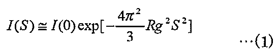
式(1)の両辺に対数を取ると、下記式(2)のようになる。

式(2)から横軸にS2、縦軸にln[I(S)]をとると直線領域が存在し、その傾きから回転半径Rgが、そのY切片からI(0)が求められる。S2に対するln[I(S)]のプロットを特にギニエプロットという。本願では、解析用ソフトウェアとしてRigaku社製のNANO-Solverを用いて、粒径分布解析を行った。
多孔質導電性粒子は、例えばカーボンまたはセラミック系材料から作られる。セラミック系材料は、例えば導電性酸化チタンのような導電化処理を施した酸化物セラミック、炭化物(カーバイド),ホウ化物(ボライド),窒化物(ナイトライド)のような非酸化物セラミックスを用いることができる。なお、導電性高分子も多くの研究が行われていることから、より軽くて高い電子導電性を有する材料が見つかれば多孔質導電性粒子として好ましい。ただし、導電性高分子は後述する製造方法のように活物質を含浸する工程での焼成温度に制約がある。
多孔質導電性粒子は、カーボンまたは導電性酸化物から作られることが好ましい。これらの材料は、工業生産上メソポアを有する多孔質導電性粒子を作製しやすいためである。
カーボンは、高比表面積活性炭またはカーボンブラックが挙げられる。導電性酸化物は、例えば導電性酸化チタンや電子導電性を有するゼオライト骨格酸化物が挙げられる。
カーボンブラックは、一般的には触媒などに用いられる、球状をなさない特異な粒子であり、外側に薄く黒鉛結晶が寄り集まったような中空シェル状粒子であることが好ましい。カーボンブラックの細孔径は、およそ数~数十nm程度で、高表面積、高吸油量が可能である。さらに、カーボンブラックは高い導電性能を有するため、第1実施形態の負極材料に特に適する。
多孔質導電性粒子は、平均粒子径10μm以上50μm以下であることが好ましい。
多孔質導電性粒子は、60vol%以上95vol%以下、より好ましくは80vol%以上95vol%以下の多孔度を有することが望ましい。
ナノチューブまたはナノワイヤーは、5nm以上50nm以下の平均直径を有することが好ましい。
多孔質導電性粒子の表面および多孔質内の少なくとも一方に形成される活物質は、多孔質導電性粒子および活物質の総量に対して60重量%以上90重量%以下、より好ましくは70重量%以上80重量%以下であることが望ましい。活物質量が90重量%を超えると、多孔質導電性粒子表面に活物質層の厚さが厚くなるため好ましくない。活物質量を60重量%未満にすると、負極の負極層に含有させた場合、負極層密度の向上が困難になる。
実施形態に係る負極材料は、BET法での比表面積が200m2/g以上400m2/g以下であることが好ましい。
ここで、比表面積の測定は粉体粒子表面に吸着占有面積の判った分子を液体窒素の温度で吸着させ,その量から試料の比表面積を求める方法を用いる。最も良く利用されるのが不活性気体の低温低湿物理吸着によるBET法であり、単分子層吸着理論であるLangmuir理論を多分子層吸着に拡張した、比表面積の計算方法として最も有名な理論である。これにより求められた比表面積のことをBET比表面積と呼んでいる。
実施形態に係る負極材料は、電極密度を向上させるために、0.3g/cm3以上のタップ密度を有することが好ましい。また、ナノチューブまたはナノファイバー形状を維持するため、タップ密度は0.9g/cm3以上1.1g/cm3以下であることが好ましい。
タップ(Tap)密度とバルク(Bulk)密度(「かさ密度」ともいう)の測定方法はASTM B-527-06に定められる方法により、測定することができる。その際には、例えば、Dual Autotap(Quantacrome corp.社)またはTap Pack Volumeter(Sahndon Southern Instruments Inc.社)のような装置を用いることができる。対象となる粉末を特定の容器に自然落下充填し、このときの質量をM(g)、体積をV(cm3)、タッピング後の体積をN(cm3)とすると以下の式で定義される。
バルク(Bulk)密度=M/V(g/cm3)
タップ(Tap)密度=M/N(g/cm3)
以上説明した第1実施形態によれば、リチウム基準で従来のチタン酸系材料と同等の1.5V付近の電極電位を示し、より高いエネルギー密度を有する非水電解質二次電池用負極材料を提供できる。
タップ(Tap)密度=M/N(g/cm3)
以上説明した第1実施形態によれば、リチウム基準で従来のチタン酸系材料と同等の1.5V付近の電極電位を示し、より高いエネルギー密度を有する非水電解質二次電池用負極材料を提供できる。
すなわち、非水電解質二次電池用負極材料は多孔質導電性粒子と、前記多孔質導電性粒子の電子導電面となりうる表面および多孔質内の少なくとも一方に形成され、結晶構造的に三次元的なナノチューブ構造およびナノワイヤー構造のうちの少なくとも一方の構造を持ち、一般式LixTiO2(式中のxは0≦x<1)にて表されるリチウムチタン複合酸化物からなる活物質を含む。具体的には、リチウムチタン複合酸化物からなる活物質はチタンイオンと酸化物イオンより構成される骨格構造部分が三次元的に安定して配置され、それらの層間部分にリチウムイオンのホストとなる空間を形成できる。また、ナノチューブおよびナノワイヤーは直径が従来のバルク材料の数μmの粒子に比べて非常に細く、かつ電解液との接触面積も増加するため、リチウムイオン拡散距離を短縮できる。さらに、活物質は電子導電性を有する多孔質導電性粒子の表面および多孔質内の少なくとも一方に強固に結合できる。その結果、電極として重要な条件である電子導電性とリチウムイオン導電性の両立が可能となる。従って、従来のバルク形状の材料に比べて、リチウムイオンホスト空間へのリチウムイオンの挿入・脱離性が向上し、さらにリチウムイオンの挿入・脱離空間が実効的に増加して容量を増大することができる。
特に、Cu-Kα線源とする小角X線散乱測定による平均粒子径が1nm以上10nm以下の範囲内でピークを持ち、かつ粒径分布が0.01nm以上30nm以下の範囲に分布し、粒径分布のピーク位置を基準にして、高角度側に分布を示すナノチューブ構造またはナノワイヤー構造を持つリチウムチタン複合酸化物からなる活物質は、リチウムイオンの導電性が良好となる平均粒径およびアスペクト比が揃っていることや、チタンイオンと酸化物イオンより構成される骨格構造部分がより安定した三次元的に配置されるため、それらの層間部分にリチウムイオンのホストとなる空間をより安定的形成することができる。
また、ナノチューブおよびナノワイヤーの直径を5nm以上50nm以下にすることによって、電解液との接触面積をより増加できるため、リチウムイオンの拡散距離を格段に短縮することができる。
このような第1実施形態に係る非水電解質二次電池用負極材料は、リチウム基準で従来のチタン酸系材料と同等の1.5V付近の電極電位を示し、より高いエネルギー密度を発現できる。
BET法での比表面積が200m2/g以上400m2/g以下の非水電解質二次電池用負極材料は、電解液との接触面が増大し、例えば充放電時のリチウムイオンが挿入・脱離入されるホストサイトが増大して、より多くのリチウムイオンがホストサイトに速やかに移動が可能になる。その結果、より一層の急速充放電性能の向上と電極容量の向上を図ることが可能になる。
(第2実施形態)
第2実施形態に係る非水電解質二次電池用負極材料の製造方法を以下に詳細に説明する。
第2実施形態に係る非水電解質二次電池用負極材料の製造方法を以下に詳細に説明する。
まず、チタンアルコキシドを各種溶媒で希釈してチタンアルコキシド溶液を調製する。チタンアルコキシドは、例えばチタンテトライソプロポキシドを用いることができる。溶媒は、例えばエタノールまたは2-プロパノールを用いることができる。
次いで、例えば平均粒径が10μm以上50μm以下の導電性多孔質粒子をチタンアルコキシド溶液に分散して分散液を調製する。
多孔質導電性粒子は、前記第1実施形態で説明した材料から作ることができる。
多孔性導電性粒子の表面が親水性の場合には、溶媒としてエタノールを用い、疎水性の場合には2-プロパノールを用いて、粒子と溶媒の濡れ性を良好にすることが好ましい。
分散液の調製にあたっては、チタンアルコキシド溶液に多孔質導電性粒子を均一に分散するために、攪拌したり、超音波を与えたりしてもよい。
次いで、分散液を減圧下に曝して前記多孔質導電粒子の表面および多孔質内のうちの少なくとも一方にチタンアルコキシド溶液を浸潤させる。つづいて、純水とエタノールを混合した溶液(エタノール濃度:20~50wt%)を滴下しながらチタンアルコキシドの加水分解反応を行ってゲル化チタン含有多孔質導電性粒子を生成する。余剰のアルコキシドをろ過分離した後、不活性ガス雰囲気中で加熱して前記多孔性導電性粒子の表面および多孔質内のうちの少なくとも一方のゲル化チタンを酸化チタンに変換する。不活性ガスは、例えば窒素ガスまたはアルゴンガスのような希ガスを用いることができる。加熱温度は400℃以上600℃以下とすることが好ましい。加熱温度を400℃未満にすると、結晶性が低下して得られた負極材料を含む負極の充放電効率が低下する虞がある。一方、加熱温度が600℃を超えると、充放電容量の低いルチル型二酸化チタンが生成する虞がある。
次いで、得られた酸化チタン含有多孔質導電性粒子をアルカリ溶液に分散して水熱処理を行う。水熱処理は、従来公知の手法により行うことができる。アルカリ溶液は、例えば水酸化ナトリウム水溶液、水酸化リチウム水溶液を用いることができる。アルカリに分散した酸化チタン含有多孔質導電性粒子を例えばオートクレーブ圧力容器を用いて加圧加熱、すなわち高温・高圧下にて水熱合成処理を行う。このとき、多孔性導電性粒子の表面および多孔質内のうちの少なくとも一方の前記酸化チタンを核として、ナノチューブ構造およびナノワイヤー構造のうちの少なくとも一方の構造を持つ酸化チタンを生成する。このように、予めカーボンと複合化したTiO2を用いることで、TiO2粒子単独を原料にした従来の方法に比べて、原料粒子の二次凝集を抑え、粒径が細かく揃った状態を提供できるため、粒径分布のシャープなナノチューブを得ることができる。
次いで、得られたナノチューブ構造およびナノワイヤー構造のうちの少なくとも一方の構造を持つ酸化チタンを有する多孔質導電性粒子を純水で水洗する。水洗は、アルカリ溶液中に含まれるナトリウムまたはリチウムのアルカリ金属イオンを洗い流す目的で行う。なお、水酸化リチウムを用いた場合、水洗工程を省いてリチウムイオンを故意に残存させ、次の処理工程を省略することもできるため好ましい。
得られたナノチューブ構造およびナノワイヤー構造のうちの少なくとも一方の構造を持つ酸化チタンを有する多孔質導電性粒子をN-メチルピロリドンのような有機溶媒中に分散した。その後、PVdFのようなバインダを添加することでペースト化し、このペーストを金属箔上に塗布することにより電極化する。次いで、電気化学的にリチウムイオンを挿入し、一般式LixTiO2(式中のxは0≦x<1)にて表されるリチウムチタン複合酸化物からなる活物質を製造する。
このとき、ナノチューブ構造およびナノワイヤー構造のうちの少なくとも一方の構造を持つ酸化チタンを有する多孔質導電性粒子を純水中に分散させ、リチウム化合物を反応させる。これによって、多孔質導電性粒子の表面および多孔質内の少なくとも一方にナノチューブ構造およびナノワイヤー構造のうちの少なくとも一方の構造を持ち、一般式LixTiO2(式中のxは0≦x<1)にて表されるリチウムチタン複合酸化物からなる活物質を形成して負極材料を製造してもよい。
リチウム化合物は、塩化リチウム、水酸化リチウム、炭酸リチウムなど特に制限されないが、塩化リチウムまたは水酸化リチウムが好ましい。これらのリチウム化合物は水溶液中で二酸化チタン酸化物表面への吸着が容易になるため好ましい。
得られた負極材料は、ひきつづき水洗、乾燥に供される。乾燥後の負極材料は結晶水を含むため、400℃以上800℃以下で加熱脱水処理を行ってもよい。
第2実施形態に係る方法によれば、多孔質導電性粒子と、前記多孔質導電性粒子の表面および多孔質内の少なくとも一方に形成されたナノチューブ構造およびナノワイヤー構造のうちの少なくとも一方の構造を持ち、一般式LixTiO2(式中のxは0≦x<1)にて表されるリチウムチタン複合酸化物からなる活物質とを含み、前述した特性を有する負極材料を製造できる。
また、第2実施形態に係る方法によればナノチューブ構造またはナノワイヤー構造を持つリチウムチタン複合酸化物からなる活物質はCu-Kα線源とする小角X線散乱測定による平均粒子径が1nm以上10nm以下の範囲内でピークを持ち、かつ粒径分布が0.01nm以上30nm以下の範囲に分布し、粒径分布のピーク位置を基準にして、高角度側に分布を示す。さらに、高い比表面積、例えばBET法での比表面積が200m2/g以上400m2/g以下を有し、かつタップ密度0.3g/cm3以上を持つ負極材料を製造することができる。
(第3実施形態)
第3実施形態に係る非水電解質二次電池は、外装材を備えている。正極、負極およびセパレータは、外装材内に収納されている。非水電解質は、外装材内に収容されている。
第3実施形態に係る非水電解質二次電池は、外装材を備えている。正極、負極およびセパレータは、外装材内に収納されている。非水電解質は、外装材内に収容されている。
以下、外装材、負極、非水電解質、正極およびセパレータについて詳述する。
1)外装材
外装材は、厚さ0.5mm以下のラミネートフィルムまたは厚さ1.0mm以下の金属製容器が用いられる。金属製容器は、厚さ0.5mm以下であることがより好ましい。
外装材は、厚さ0.5mm以下のラミネートフィルムまたは厚さ1.0mm以下の金属製容器が用いられる。金属製容器は、厚さ0.5mm以下であることがより好ましい。
外装材の形状は、扁平型(薄型)、角型、円筒型、コイン型、ボタン型等が挙げられる。外装材は、電池寸法に応じて、例えば携帯用電子機器等に積載される小型電池用外装材、二輪乃至四輪の自動車等に積載される大型電池用外装材が挙げられる。
ラミネートフィルムは、樹脂フィルム間に金属層を介在した多層フィルムが用いられる。金属層は、軽量化のためにアルミニウム箔もしくはアルミニウム合金箔が好ましい。樹脂フィルムは、例えばポリプロピレン(PP)、ポリエチレン(PE)、ナイロン、ポリエチレンテレフタレート(PET)等の高分子材料を用いることができる。ラミネートフィルムは、熱融着によりシールを行って外装材の形状に成形することができる。
金属製容器は、アルミニウムまたはアルミニウム合金等がから作られる。アルミニウム合金としては、マグネシウム、亜鉛、ケイ素等の元素を含む合金が好ましい。アルミニウムまたはアルミニウム合金において鉄、銅、ニッケル、クロム等の遷移金属の含有量は100ppm以下にすることが好ましい。
2)負極
負極は、集電体と、集電体の片面または両面に形成され、負極材料および結着剤を含む負極層を有する。
負極は、集電体と、集電体の片面または両面に形成され、負極材料および結着剤を含む負極層を有する。
負極材料は、第1実施形態で説明したのと同様な構成、すなわち多孔質導電性粒子と、この多孔質導電性粒子の表面および多孔質内の少なくとも一方に形成されたナノチューブ構造およびナノワイヤー構造のうちの少なくとも一方の構造を持ち、一般式LixTiO2(式中のxは0≦x<1)にて表される活物質とを含む。負極材料中のナノチューブ構造またはナノワイヤー構造の活物質は、Cu-Kα線源とする小角X線散乱測定による平均粒子径が1nm以上10nm以下の範囲内でピークを持ち、かつ粒径分布が0.01nm以上30nm以下の範囲に分布し、粒径分布のピーク位置を基準にして、高角度側に分布を示すことが好ましい。負極材料は、BET法での比表面積が200m2/g以上400m2/g以下であることが好ましい。負極材料は、0.3g/cm3以上のタップ密度を有することが好ましい。
結着剤は、例えばポリテトラフルオロエチレン(PTFE)、ポリフッ化ビニリデン(PVdF)、フッ素系ゴム、スチレンブタジェンゴム等が挙げられる。
結着剤は、負極層中に2重量%以上30重量%以下の範囲で配合されていることが好ましい。結着剤の量を2重量%未満であると、負極層と集電体の結着性が低下し、サイクル特性が低下する虞がある。一方、高容量化の観点から、結着剤は30重量%以下であることが好ましい。導電剤も負極層中に30重量%以下の割合で配合されることが好ましい。
集電体は、負極材料の活物質のリチウムの吸蔵・放出電位にて電気化学的に安定である材料が用いられる。集電体は、銅、ニッケル、ステンレス、またはアルミニウムから作られることが好ましい。集電体の平均厚さは5~20μmであることが好ましい。このような厚さを有する集電体は、負極の強度と軽量化をバランスできる。
負極は、例えば負極材料および結着剤を汎用されている溶媒に懸濁してスラリーを調製し、このスラリーを集電体に塗布し、乾燥し、負極層を形成した後、プレスを施すことにより作製される。
また、負極の作製において負極材料および結着剤をペレット状に形成し、負極層として用いてもよい。
3)非水電解質
非水電解質は、電解質を有機溶媒に溶解することにより調製される液状非水電解質、液状電解質と高分子材料を複合化したゲル状非水電解質等が挙げられる。
非水電解質は、電解質を有機溶媒に溶解することにより調製される液状非水電解質、液状電解質と高分子材料を複合化したゲル状非水電解質等が挙げられる。
液状非水電解質は、電解質を0.5モル/L以上2.5モル/L以下の濃度で有機溶媒に溶解することにより調製される。
電解質としては、例えば、過塩素酸リチウム(LiClO4)、六フッ化リン酸リチウム(LiPF6)、四フッ化ホウ酸リチウム(LiBF4)、六フッ化砒素リチウム(LiAsF6)、トリフルオロメタスルホン酸リチウム(LiCF3SO3)、ビストリフルオロメチルスルホニルイミトリチウム[LiN(CF3SO2)2]等のリチウム塩、またはこれらの混合物を挙げることができる。電解質は高電位でも酸化し難いものであることが好ましく、LiPF6が最も好ましい。
有機溶媒は、例えばプロピレンカーボネート(PC)、エチレンカーボネート(EC)、ビニレンカーボネート等の環状カーボネートや、ジエチルカーボネート(DEC)、ジメチルカーボネート(DMC)、メチルエチルカーボネート(MEC)等の鎖状カーボネートや、テトラヒドロフラン(THF)、2メチルテトラヒドロフラン(2MeTHF)、ジオキソラン(DOX)等の環状エーテルや、ジメトキシエタン(DME)、ジエトエタン(DEE)等の鎖状エーテルや、γ-ブチロラクトン(GBL)、アセトニトリル(AN)、スルホラン(SL)等の単独または混合溶媒を挙げることができる。
高分子材料は、例えばポリフッ化ビニリデン(PVdF)、ポリアクリロニトリル(PAN)、ポリエチレンオキサイド(PEO)等を挙げることができる。
なお、非水電解質はリチウムイオンを含有した常温溶融塩(イオン性融体)、高分子固体電解質、無機固体電解質等を用いてもよい。
常温溶融塩(イオン性融体)は、有機物カチオンとアニオンの組合せからなる有機塩の内、常温(15~25℃)で液体として存在しうる化合物を指す。常温溶融塩としては、単体で液体として存在する常温溶融塩、電解質と混合させることで液体となる常温溶融塩、有機溶媒に溶解させることで液体となる常温溶融塩等が挙げられる。なお、一般に、非水電解質二次電池に用いられる常温溶融塩の融点は、25℃以下である。また、有機物カチオンは、一般に4級アンモニウム骨格を有する。
高分子固体電解質は、電解質を高分子材料に溶解し固体化し調製する。
無機固体電解質は、リチウムイオン伝導性を有する固体物質である。
4)正極
正極は、集電体と、この集電体の片面もしくは両面に形成され、活物質および結着剤を含む正極層とを有する。
正極は、集電体と、この集電体の片面もしくは両面に形成され、活物質および結着剤を含む正極層とを有する。
活物質は、例えば酸化物、硫化物等が挙げられる。活物質は、具体的には例えばリチウムを吸蔵した二酸化マンガン(MnO2)、酸化鉄、酸化銅、酸化ニッケル、リチウムマンガン複合酸化物(例えばLixMn2O4またはLixMnO2)、リチウムニッケル複合酸化物(例えばLixNiO2)、リチウムコバルト複合酸化物(例えばLixCoO2)、リチウムニッケルコバルト複合酸化物(例えばLiNi1-yCoyO2)、リチウムマンガンコバルト複合酸化物(例えばLixMnyCo1-yO2)、スピネル型リチウムマンガンニッケル複合酸化物(LixMn2-yNiyO4)、オリビン構造を有するリチウムリン酸化物(LixFePO4,LixFe1-yMnyPO4,LixCoPO4など)、硫酸鉄[Fe2(SO4)3]、バナジウム酸化物(例えばV2O5)などが挙げられる。ここでx、yは、それぞれ0<x≦1、0<y≦1であることが好ましい。
高い正極電圧が得られる活物質は、リチウムマンガン複合酸化物(LixMn2O4)、リチウムニッケル複合酸化物(LixNiO2)、リチウムコバルト複合酸化物(LixCoO2)、リチウムニッケルコバルト複合酸化物(LiNi1-yCoyO2)、スピネル型リチウムマンガンニッケル複合酸化物(LixMn2-yNiyO4)、リチウムマンガンコバルト複合酸化物(LixMnyCo1-yO2)、リチウムリン酸鉄(LixFePO4)、リチウムニッケルコバルトマンガン複合酸化物などが挙げられる。ここでx、yは、それぞれ0<x≦1、0<y≦1であることが好ましい。
中でも、常温溶融塩を含む非水電解質を用いる場合にはリチウムリン酸鉄、LixVPO4F、リチウムマンガン複合酸化物、リチウムニッケル複合酸化物、リチウムニッケルコバルト複合酸化物を用いることがサイクル寿命の観点から好ましい。これは、正極活物質と常温溶融塩との反応性が少なくなるためである。正極活物質の一次粒径は、100nm以上1μm以下であると好ましい。一次粒径が100nm以上の正極活物質は、工業生産の上で取り扱い易くなる。一次粒径が1μm以下正極活物質は、リチウムイオンの固体内拡散をスムーズに進行させることが可能になる。
活物質の比表面積は、0.1m2/g以上10m2/g以下であることが好ましい。0.1m2/g以上の比表面積を有する活物質は、リチウムイオンの吸蔵・放出サイトを十分に確保できる。10m2/g以下の比表面積を有する活物質は、工業生産の上で取り扱い易く、かつ良好な充放電サイクル性能を確保できる。
活物質と集電体の結着等を目的とする結着剤は、例えばポリテトラフルオロエチレン(PTFE)、ポリフッ化ビニリデン(PVdF)、フッ素系ゴム等が挙げられる。
導電剤は、集電性能を高め、かつ集電体との接触抵抗を抑えるために必要に応じて配合することができる。導電剤は、例えばアセチレンブラック、カーボンブラック、黒鉛等の炭素質物を挙げることができる。
活物質および結着剤の配合割合は、活物質は80重量%以上98重量%以下、結着剤は2重量%以上20重量%以下の範囲にすることが好ましい。結着剤の量を2重量%以上にすることにより十分な電極強度が得られ、20重量%以下にすることにより電極の絶縁体の配合量を減少させ、内部抵抗を減少できる。
導電剤を加える場合には、その量を3重量%以上にすることにより導電剤の添加効果が得られ、15重量%以下にすることにより、高温保存下での導電剤表面での非水電解質の分解を低減することができる。
集電体は、アルミニウム箔またはアルミニウム合金箔であることが好ましい。
アルミニウム箔またはアルミニウム合金箔の平均厚さは、5μm以上20μm以下、より好ましくは15μm以下にすることが望ましい。アルミニウム箔の純度は99wt%以上が好ましい。アルミニウム合金は、マグネシウム、亜鉛、ケイ素などの元素を含む合金が好ましい。アルミニウム箔またはアルミニウム合金箔に含まれる鉄、銅、ニッケル、クロムなどの遷移金属の含有量は、1wt%以下にすることが好ましい。
正極は、例えば活物質、結着剤および必要に応じて配合される導電剤を適当な溶媒に懸濁してスラリーを調製し、このスラリーを集電体に塗布し、乾燥し、正極層を形成した後、プレスを施すことにより作製される。
また、正極の作製において活物質、結着剤および必要に応じて配合される導電剤をペレット状に形成し、正極層として用いてもよい。
5)セパレータ
セパレータは、例えばポリエチレン、ポリプロピレン、セルロース、またはポリフッ化ビニリデン(PVdF)を含む多孔質フィルム、合成樹脂製不織布等を挙げることができる。中でも、ポリエチレン又はポリプロピレンからなる多孔質フィルムは、一定温度において溶融し、電流を遮断することが可能であり、安全性向上の観点から好ましい。
セパレータは、例えばポリエチレン、ポリプロピレン、セルロース、またはポリフッ化ビニリデン(PVdF)を含む多孔質フィルム、合成樹脂製不織布等を挙げることができる。中でも、ポリエチレン又はポリプロピレンからなる多孔質フィルムは、一定温度において溶融し、電流を遮断することが可能であり、安全性向上の観点から好ましい。
前述した負極、正極およびセパレータを有する電極群は、捲回構造に限らず、積層構造でもよい。
次に、第3実施形態に係る非水電解質二次電池を図1、図2を参照してより具体的に説明する。図1は、第3実施形態に係る扁平型非水電解質二次電池の断面図、図2は図1のA部の拡大断面図を示す。
扁平状の捲回電極群1は、2枚の樹脂フィルムの間に金属層を介在したラミネートフィルムからなる袋状外装材2内に収納されている。扁平状の捲回電極群1は、外側から負極3、セパレータ4、正極5、セパレータ4の順で積層した積層物を渦巻状に捲回し、プレス成型することにより形成される。最外殻の負極3は、図2に示すように負極集電体3aの内面側の片面に前述したリチウムチタン複合酸化物を負極活物質として含む負極層3bを形成した構成を有し、その他の負極3は、負極集電体3aの両面に負極層3bを形成して構成されている。正極5は、正極集電体5aの両面に正極層3bを形成して構成されている。
捲回電極群1の外周端近傍において、負極端子6は最外殻の負極3の負極集電体3aに接続され、正極端子7は内側の正極5の正極集電体5aに接続されている。これらの負極端子6および正極端子7は、袋状外装材2の開口部から外部に延出されている。例えば液状非水電解質は、袋状外装材2の開口部から注入されている。袋状外装材2の開口部を負極端子6および正極端子7を挟んでヒートシールすることにより捲回電極群1および液状非水電解質を完全密封している。
負極端子は、上述の負極活物質のLi吸蔵放出電位にて電気化学的に安定であり、かつ導電性を備える材料から形成することができる。具体的には、銅、ニッケル、ステンレスまたはアルミニウムが挙げられる。接触抵抗を低減するために、負極集電体と同様の材料が好ましい。
正極端子は、リチウムイオン金属に対する電位が3V以上5V以下の範囲における電気的安定性と導電性とを備える材料から形成することができる。具体的には、Mg、Ti、Zn、Mn、Fe、Cu、Si等の元素を含むアルミニウム合金、アルミニウムが挙げられる。接触抵抗を低減するために、正極集電体と同様の材料が好ましい。
第3実施形態に係る非水電解質二次電池は、前述した図1および図2に示す構成のものに限らず、例えば図3および図4に示す構成にすることができる。図3は、第3実施形態に係る別の扁平型非水電解質二次電池を模式的に示す部分切欠斜視図で、図4は図3のB部の拡大断面図である。
積層型電極群11は、2枚の樹脂フィルムの間に金属層を介在したラミネートフィルムからなる外装材12内に収納されている。積層型電極群11は、図4に示すように正極13と負極14とをその間にセパレータ15を介在させながら交互に積層した構造を有する。正極13は複数枚存在し、それぞれが集電体13aと、集電体13aの両面に担持された正極活物質含有層13bとを備える。負極14は複数枚存在し、それぞれが集電体14aと、集電体14aの両面に担持された負極活物質含有層14bとを備える。各負極14の集電体14aは、一辺が正極13から突出している。突出した集電体14aは、帯状の負極端子16に電気的に接続されている。帯状の負極端子16の先端は、外装部材11から外部に引き出されている。また、図示しないが、正極13の集電体13aは、集電体14aの突出辺と反対側に位置する辺が負極14から突出している。負極14から突出した集電体13aは、帯状の正極端子17に電気的に接続されている。帯状の正極端子17の先端は、負極端子16とは反対側に位置し、外装部材11の辺から外部に引き出されている。
このような第3実施形態によれば、第1実施形態で説明したリチウム基準で従来のチタン酸系材料と同等の1.5V付近の電極電位を示し、より高いエネルギー密度を有するリチウムチタン複合酸化物からなる負極活物質を含む負極を備えるため、安定した繰り返し急速充放電性能を有する非水電解質二次電池を提供できる。
(第4実施形態)
第4実施形態に係る電池パックは、前述した非水電解質二次電池(単電池)を複数有し、各単電池を互いに電気的に直列、並列、または直列および並列に接続して配置されている。
第4実施形態に係る電池パックは、前述した非水電解質二次電池(単電池)を複数有し、各単電池を互いに電気的に直列、並列、または直列および並列に接続して配置されている。
このような電池パックを図5および図6を参照して詳細に説明する。単電池には、図1に示す扁平型電池を使用することができる。
前述した図1に示す扁平型非水電解質二次電池から構成される複数の単電池21は、外部に延出した負極端子6および正極端子7が同じ向きに揃えられるように積層され、粘着テープ22で締結することにより組電池23を構成している。これらの単電池21は、図6に示すように互いに電気的に直列に接続されている。
プリント配線基板24は、負極端子6および正極端子7が延出する単電池21側面と対向して配置されている。プリント配線基板24には、図6に示すようにサーミスタ25、保護回路26および外部機器への通電用端子27が搭載されている。なお、組電池23と対向する保護回路基板24の面には組電池23の配線と不要な接続を回避するために絶縁板(図示せず)が取り付けられている。
正極側リード28は、組電池23の最下層に位置する正極端子7に接続され、その先端はプリント配線基板24の正極側コネクタ29に挿入されて電気的に接続されている。負極側リード30は、組電池23の最上層に位置する負極端子6に接続され、その先端はプリント配線基板24の負極側コネクタ31に挿入されて電気的に接続されている。これらのコネクタ29,31は、プリント配線基板24に形成された配線32,33を通して保護回路26に接続されている。
サーミスタ25は、単電池21の温度を検出し、その検出信号は保護回路26に送信される。保護回路26は、所定の条件で保護回路26と外部機器への通電用端子27との間のプラス側配線34aおよびマイナス側配線34bを遮断できる。所定の条件とは、例えばサーミスタ25の検出温度が所定温度以上になったときである。また、所定の条件とは単電池21の過充電、過放電、過電流等を検出したときである。この過充電等の検出は、個々の単電池21もしくは単電池21全体について行われる。個々の単電池21を検出する場合、電池電圧を検出してもよいし、正極電位もしくは負極電位を検出してもよい。後者の場合、個々の単電池21中に参照極として用いるリチウム電極が挿入される。図5および図6の場合、単電池21それぞれに電圧検出のための配線35を接続し、これら配線35を通して検出信号が保護回路26に送信される。
正極端子7および負極端子6が突出する側面を除く組電池23の三側面には、ゴムもしくは樹脂からなる保護シート36がそれぞれ配置されている。
組電池23は、各保護シート36およびプリント配線基板24と共に収納容器37内に収納される。すなわち、収納容器37の長辺方向の両方の内側面と短辺方向の内側面それぞれに保護シート36が配置され、短辺方向の反対側の内側面にプリント配線基板24が配置される。組電池23は、保護シート36およびプリント配線基板24で囲まれた空間内に位置する。蓋38は、収納容器37の上面に取り付けられている。
なお、組電池23の固定には粘着テープ22に代えて、熱収縮テープを用いてもよい。この場合、組電池の両側面に保護シートを配置し、熱収縮チューブを周回させた後、熱収縮チューブを熱収縮させて組電池を結束させる。
図5、図6では単電池21を直列接続した形態を示したが、電池容量を増大させるためには並列に接続してもよい。組み上がった電池パックを直列、並列に接続することもできる。
また、電池パックの態様は用途により適宜変更される。電池パックの用途としては、大電流特性でのサイクル特性が望まれるものが好ましい。具体的には、デジタルカメラの電源用や、二輪乃至四輪のハイブリッド電気自動車、二輪乃至四輪の電気自動車、アシスト自転車等の車載用が挙げられる。特に、車載用が好適である。
以下、本発明の実施例に基づいてさらに詳細に説明するが、本発明はこれら実施例のみに限定されるものではない。なお、反応で得られた結晶相の同定及び結晶構造の推定は、Cu-Kα線を用いた粉末X線回折法によって行い、比表面積は前述したBET法により行った。また、生成物の組成はICP法により分析を行い目的物が得られていることを確認した。
(負極材料の合成例1)
チタンイソプロポキシドと2-プロパノールを混合した溶液中に中空シェル構造のカーボンブラック(ケッチェンブラックEC600(商標))を分散混合し、攪拌した後、減圧下に曝した。このとき、カーボンブラックの中空シェル部分にチタンイソプロポキシド溶液が含浸された。カーボンブラックは、BET法での比表面積が900m2/g、粒径が39.5nmであった。十分に含浸させた後、エタノールと純水を混合した水溶液をゆっくりと滴下しながら攪拌して、加水分解反応を行ってゲル化チタン含有カーボンブラックを生成した。つづいて、余剰のチタンイソプロポキシド溶液をろ過分離した。室温で12時間乾燥させた後、60℃で24時間に乾燥させ、アルゴン雰囲気中、400℃で5時間焼成した。このとき、ゲル化チタンが二酸化チタンに変換された。
チタンイソプロポキシドと2-プロパノールを混合した溶液中に中空シェル構造のカーボンブラック(ケッチェンブラックEC600(商標))を分散混合し、攪拌した後、減圧下に曝した。このとき、カーボンブラックの中空シェル部分にチタンイソプロポキシド溶液が含浸された。カーボンブラックは、BET法での比表面積が900m2/g、粒径が39.5nmであった。十分に含浸させた後、エタノールと純水を混合した水溶液をゆっくりと滴下しながら攪拌して、加水分解反応を行ってゲル化チタン含有カーボンブラックを生成した。つづいて、余剰のチタンイソプロポキシド溶液をろ過分離した。室温で12時間乾燥させた後、60℃で24時間に乾燥させ、アルゴン雰囲気中、400℃で5時間焼成した。このとき、ゲル化チタンが二酸化チタンに変換された。
次いで、得られた二酸化チタンとカーボンブラックの複合材料1gを10mol/Lの濃度に調整した水酸化ナトリウム水溶液60mLとエタノール60mLの混合溶液中に入れ、十分に攪拌分散した。この分散液をポリテトラフルオロエチレン製内壁を有するステンレス製オートクレーブ圧力容器150mL中に移し、180℃で24時間加熱した。室温まで冷却した後、生成物を0.5Mの塩酸で洗浄し、水洗処理を行った。これらを減圧乾燥機に入れ、80℃で12時間乾燥した。次に、この試料を350℃で12時間加熱することにより、カーボンブラックに二酸化チタンのナノチューブ・ナノワイヤーを複合化した複合材料(負極材料)を製造した。
得られた負極材料のCu-Kα線による粉末X線回折測定結果を図7に示す。測定条件は、走査速度3deg/min、ステップ幅0.2deg、管電圧40kV、管電流20mAとした。この結果から、アナターゼ型酸化チタン(TiO2)の生成を確認した。一方、得られた試料の目視からカーボンブラックの持つ黒色が確認されている。これらから、回折線ピークは細孔部に取り込まれた酸化チタンによる反射と考えられる。
また、この試料の小角X線散乱測定から得られた粒径分布の結果を図8に示す。Rigaku社のRINT2500を用いて測定を行った。X線源はCuターゲットを用いて50kV-300mAの条件とした。測定条件は、ステップスキャン法(FT法)にて、ステップ間隔0.005度、計数時間5秒、走査範囲0.06度~5.00度の範囲とした。透過法による測定のため、ポリエチレンテレフタレート(PET)フィルム袋に測定試料を充填して、専用ホルダーにセットした。解析時には、PETフィルムの影響を取り除くため、PETフィルムのみで測定したブランク情報を差し引いた。
この測定結果から、Cu-Kα線源とする小角X線散乱測定による平均粒子径が7.03nmであり、ピークが1~10nmの範囲内でシャープに立ち上がりながらも、粒径分布が0.05~21.0nmの範囲に分布した。また、粒径分布のピーク位置を基準にして、高角度側に分布を示すことから、カーボン複合化による効果で平均粒径やアスペクト比の整ったチタン酸化物および導電性多孔質粒子からなる複合材料であることを確認した。あらかじめカーボンと複合化したTiO2は、TiO2粒子単独に比べて、粒子の二次凝集を抑え、粒径が細かく揃った状態を提供できるため、粒径分布のシャープなナノチューブを得ることができる。
<負極材料の合成例2>
従来公知の材料として、二酸化チタンのナノチューブ・ナノワイヤーを合成した。すなわち、出発原料として、市販の微粒子二酸化チタン(平均粒子径100nm)を用いた。微粒子二酸化チタン1gを10mol/Lの濃度に調整した水酸化ナトリウム水溶液60mLとエタノール60mLの混合溶液中に入れ、十分に攪拌分散した。この分散液をポリテトラフルオロエチレン製内壁を有するステンレス製オートクレーブ圧力容器150mL中に移し、180℃で24時間加熱した。室温まで冷却した後、生成物を0.5Mの塩酸で洗浄し、水洗処理を行った。これらを減圧乾燥機に入れ、80℃で12時間乾燥した。
従来公知の材料として、二酸化チタンのナノチューブ・ナノワイヤーを合成した。すなわち、出発原料として、市販の微粒子二酸化チタン(平均粒子径100nm)を用いた。微粒子二酸化チタン1gを10mol/Lの濃度に調整した水酸化ナトリウム水溶液60mLとエタノール60mLの混合溶液中に入れ、十分に攪拌分散した。この分散液をポリテトラフルオロエチレン製内壁を有するステンレス製オートクレーブ圧力容器150mL中に移し、180℃で24時間加熱した。室温まで冷却した後、生成物を0.5Mの塩酸で洗浄し、水洗処理を行った。これらを減圧乾燥機に入れ、80℃で12時間乾燥した。
次いで、この試料を350℃で12時間加熱することにより、ナノチューブ・ナノワイヤーを得た。この材料の粉末X線回折測定結果は、図7と酷似しており、活物質の生成相は同様にアナターゼ型の酸化チタンであった。
得られたアナターゼ型酸化チタンからなるナノチューブ・ナノワイヤーに導電助剤としてアセチレンブラックを添加し、乳鉢にて混合した。
得られた混合物の小角X線散乱測定結果を図9に示す。この測定結果から、Cu-Kα線源とする小角X線散乱測定による平均粒子径が12.25nmで、かつ1~20nmの範囲で広がったブロードなピークが見られた。また、粒径分布が1.7~29.0nmの範囲に分布しており、粒径やアスペクト比に分布のあるカーボンブラックとチタン酸化物の混合物で構成されていることが分かった。
<実施例1および比較例1>
合成例1,2で得た負極材料粉末にバインダとしてポリテトラフルオロエチレンを重量比で10%混合した。つづいて、これらの混合物をNMP(nメチルピロリド)に分散してスラリーを調製した。各スラリーをドクターブレードを用いてアルミニウム箔上に約100μm厚さの塗膜を形成した。ひきつづき、これらを減圧雰囲気下80℃で12時間乾燥した後、4cm2の正方形状に切り出しで電極(負極)作製した。
合成例1,2で得た負極材料粉末にバインダとしてポリテトラフルオロエチレンを重量比で10%混合した。つづいて、これらの混合物をNMP(nメチルピロリド)に分散してスラリーを調製した。各スラリーをドクターブレードを用いてアルミニウム箔上に約100μm厚さの塗膜を形成した。ひきつづき、これらを減圧雰囲気下80℃で12時間乾燥した後、4cm2の正方形状に切り出しで電極(負極)作製した。
各電極の対極として金属リチウム箔を用いた。電極と金属リチウム箔との間にセパレータとしてガラスフィルターを挟んで電気化学測定セルとした。電解液にはヘキサフルオロリン酸リチウムをエチレンカーボネート溶媒中に1Mの濃度で溶解させたものを用いた。
電気化学測定セルは、リチウム金属を対極としているため、電極の電位は対極に比して貴となる。このため、充放電の方向は、電極を負極として用いたときと反対になる。ここで、混乱を避けるため、リチウムイオンが電極に挿入される方向を充電、脱離する方向を放電という呼称で統一することにする。
<初回充放電容量の評価>
実施例1および比較例1の電気化学測定セルについて、室温にて金属リチウム電極基準で1.0V~2.5Vの電位範囲で充放電試験を行った。実施例1および比較例1の測定セルの初回充放電カーブを図10に示す。図10から明らかなように実施例1と比較例1の測定セルの充放電カーブを比較すると、実施例1の測定セルは充電容量、放電容量がともに比較例1の測定セルより高いことがわかる。
実施例1および比較例1の電気化学測定セルについて、室温にて金属リチウム電極基準で1.0V~2.5Vの電位範囲で充放電試験を行った。実施例1および比較例1の測定セルの初回充放電カーブを図10に示す。図10から明らかなように実施例1と比較例1の測定セルの充放電カーブを比較すると、実施例1の測定セルは充電容量、放電容量がともに比較例1の測定セルより高いことがわかる。
さらに、初回充電容量と初回放電容量の割合(初回充放電効率)は、実施例1の測定セルでは81%と高く、比較例1の測定セルでは68%と低かった。これは、実施例1の電極に含まれる負極材料であるナノチューブ・ナノファイバーとカーボンの複合化による効果であり、単純にカーボンと混合した比較例1の電極に含まれる負極材料に比べて、高い充放電容量及び充放電効率を示すことがわかる。
<充放電サイクル特性の評価>
次いで、実施例1および比較例1の電気化学測定セルについて、室温にて金属リチウム電極基準で1.0V~2.5Vの電位範囲で充放電を繰り返し行いながら、放電容量維持率を調べた。容量維持率は、電流値0.5mA/cm2の時の初回放電容量を100%として図11に示す。
次いで、実施例1および比較例1の電気化学測定セルについて、室温にて金属リチウム電極基準で1.0V~2.5Vの電位範囲で充放電を繰り返し行いながら、放電容量維持率を調べた。容量維持率は、電流値0.5mA/cm2の時の初回放電容量を100%として図11に示す。
図11から明らかなように小角X線散乱測定において特定のI(0)及びRgを持つアナターゼ型二酸化チタンナノチューブ/ワイヤーを負極材料を含む電極を用いた実施例1の測定セルは、比較例の測定セルに比べ、高い容量維持率を示すことが分かる。単純にカーボンブラックと二酸化チタンナノチューブ/ワイヤーを混合した負極材料を含む電極を用いた比較例1の測定セルは、繰り返し充放電の耐久性が低いことが明らかである。
以上、本発明の実施の形態を説明したが、本発明はこれらに限られず、特許請求の範囲に記載の発明の要旨の範疇において様々に変更可能である。また、本発明は、実施段階ではその要旨を逸脱しない範囲で種々に変形することが可能である。さらに、上記実施形態に開示されている複数の構成要素を適宜組み合わせることにより種々の発明を形成できる。
Claims (11)
- 多孔質導電性粒子と、前記多孔質導電性粒子の表面および多孔質内の少なくとも一方に形成されたナノチューブ構造およびナノワイヤー構造のうちの少なくとも一方の構造を持ち、一般式LixTiO2(式中のxは0≦x<1)にて表されるリチウムチタン複合酸化物からなる活物質と、を含む非水電解質二次電池用負極材料。
- 前記活物質は、Cu-Kα線源とする小角X線散乱測定による平均粒子径が1nm以上10nm以下の範囲内でピークを持ち、かつ粒径分布が0.01nm以上30nm以下の範囲に分布し、粒径分布のピーク位置を基準にして、高角度側に分布を示す請求項1記載の非水電解質二次電池用負極材料。
- 前記多孔質導電性粒子は、平均粒子径10μm以上50μm以下のカーボンまたは導電性酸化物である請求項1記載の非水電解質二次電池用負極材料。
- 前記ナノチューブまたはナノワイヤーは、5nm以上50nm以下の平均直径を有する請求項1記載の非水電解質二次電池用負極材料。
- BET法での比表面積が200m2/g以上400m2/g以下である請求項1記載の非水電解質二次電池用負極材料。
- タップ密度が0.3g/cm3以上1.1g/cm3以下である請求項1記載の非水電解質二次電池用負極材料。
- チタンアルコキシド溶液中に多孔質導電粒子を分散させて分散液を調製すること;
前記分散液を減圧下に曝して前記多孔質導電粒子の表面および多孔質内のうちの少なくとも一方にチタンアルコキシド溶液を浸潤させること;
前記湿潤後に加水分解反応を行ってゲル化チタン含有多孔質導電性粒子を生成すること;
前記ゲル化チタン含有多孔質導電性粒子を不活性ガス雰囲気中で焼成して前記多孔性導電性粒子の表面および多孔質内のうちの少なくとも一方のゲル化チタンを酸化チタンに変換すること;
得られた酸化チタン含有多孔質導電性粒子をアルカリ溶液に分散させた後、加圧加熱して多孔性導電性粒子の表面および多孔質内のうちの少なくとも一方の前記酸化チタンをナノチューブ構造およびナノワイヤー構造のうちの少なくとも一方の構造を持つ酸化チタンに変換すること;および
得られたナノチューブ構造およびナノワイヤー構造のうちの少なくとも一方の構造を持つ酸化チタンを有する多孔質導電性粒子にリチウム化合物を反応させることにより、前記多孔質導電性粒子の表面および多孔質内の少なくとも一方にナノチューブ構造およびナノワイヤー構造のうちの少なくとも一方の構造を持ち、一般式LixTiO2(式中のxは0≦x<1)にて表されるリチウムチタン複合酸化物からなる活物質を形成すること;
を含む非水電解質二次電池用負極材料の製造方法。 - 前記アルカリ溶液が水酸化ナトリウムまたは水酸化リチウムを含む水溶液で、かつ前記リチウム化合物が塩化リチウムまたは水酸化リチウムである請求項7記載の非水電解質二次電池用負極材料の製造方法。
- リチウムを吸蔵・放出可能な正極;
多孔質導電性粒子と、前記多孔質導電性粒子の表面および多孔質内の少なくとも一方に形成されたナノチューブ構造およびナノワイヤー構造のうちの少なくとも一方の構造を持ち、一般式LixTiO2(式中のxは0≦x<1)にて表されるリチウムチタン複合酸化物からなる活物質とを含む負極材料を含有する負極;および
非水電解質;
を備える非水電解質二次電池。 - 前記負極材料中の前記活物質は、Cu-Kα線源とする小角X線散乱測定による平均粒子径が1nm以上10nm以下の範囲内でピークを持ち、かつ粒径分布が0.01nm以上30nm以下の範囲に分布し、粒径分布のピーク位置を基準にして、高角度側に分布を示す請求項9記載の非水電解質二次電池。
- 請求項9記載の非水電解質二次電池を複数備え、これら電池が互いに電気的に直列、並列または直列および並列に接続されているパック電池。
Priority Applications (1)
| Application Number | Priority Date | Filing Date | Title |
|---|---|---|---|
| US13/238,853 US8709658B2 (en) | 2009-03-25 | 2011-09-21 | Negative electrode material for non-aqueous electrolyte secondary battery, method for manufacturing negative electrode material for non-aqueous electrolyte secondary battery, non-aqueous electrolyte secondary battery, and battery pack |
Applications Claiming Priority (2)
| Application Number | Priority Date | Filing Date | Title |
|---|---|---|---|
| JP2009-073122 | 2009-03-25 | ||
| JP2009073122A JP5380124B2 (ja) | 2009-03-25 | 2009-03-25 | 非水電解質二次電池用負極材料、非水電解質二次電池用負極材料の製造方法、非水電解質二次電池および電池パック |
Related Child Applications (1)
| Application Number | Title | Priority Date | Filing Date |
|---|---|---|---|
| US13/238,853 Continuation US8709658B2 (en) | 2009-03-25 | 2011-09-21 | Negative electrode material for non-aqueous electrolyte secondary battery, method for manufacturing negative electrode material for non-aqueous electrolyte secondary battery, non-aqueous electrolyte secondary battery, and battery pack |
Publications (1)
| Publication Number | Publication Date |
|---|---|
| WO2010109722A1 true WO2010109722A1 (ja) | 2010-09-30 |
Family
ID=42780424
Family Applications (1)
| Application Number | Title | Priority Date | Filing Date |
|---|---|---|---|
| PCT/JP2009/069504 Ceased WO2010109722A1 (ja) | 2009-03-25 | 2009-11-17 | 非水電解質二次電池用負極材料、非水電解質二次電池用負極材料の製造方法、非水電解質二次電池および電池パック |
Country Status (3)
| Country | Link |
|---|---|
| US (1) | US8709658B2 (ja) |
| JP (1) | JP5380124B2 (ja) |
| WO (1) | WO2010109722A1 (ja) |
Cited By (3)
| Publication number | Priority date | Publication date | Assignee | Title |
|---|---|---|---|---|
| US20120107695A1 (en) * | 2010-11-02 | 2012-05-03 | Electronics And Telecommunications Research Institute | Lithium rechargeable battery |
| US20140162117A1 (en) * | 2011-08-26 | 2014-06-12 | Kabushiki Kaisha Toshiba | Nonaqueous electrolyte secondary battery and production method thereof |
| US12388081B2 (en) * | 2011-09-29 | 2025-08-12 | Uchicago Argonne, Llc | Sodium-ion electrochemical cells and batteries |
Families Citing this family (12)
| Publication number | Priority date | Publication date | Assignee | Title |
|---|---|---|---|---|
| JP5100892B2 (ja) * | 2009-07-31 | 2012-12-19 | 株式会社東芝 | 非水電解質電池、それに用いる活物質、その製造方法、チタン酸アルカリ化合物の製造方法、及び電池パック |
| US10112156B2 (en) | 2011-03-03 | 2018-10-30 | Wisys Technology Foundation, Inc. | Thermodynamic solutions of metal chalcogenides and mixed metal oxides and chalcogenides |
| KR101319461B1 (ko) * | 2011-08-26 | 2013-10-29 | 경상대학교산학협력단 | 리튬 금속 산화물 나노 구조체가 형성된 전극-집전체 일체형 전극소자 및 이의 제조 방법 |
| DE102012205937A1 (de) * | 2012-04-12 | 2013-10-17 | Robert Bosch Gmbh | Sensorvorrichtung für einen elektrochemischen Energiespeicher, elektrochemischer Energiespeicher, Verfahren zum Herstellen einer Sensorvorrichtung für einen elektrochemischen Energiespeicher und Verfahren zum elektrischen Kontaktieren einer Sensorvorrichtung in einem elektrochemischen Energiespeicher |
| KR101336286B1 (ko) * | 2012-11-13 | 2013-12-03 | 재단법인대구경북과학기술원 | 탄소나노섬유 복합체의 제조방법 및 이를 통해 제조된 탄소나노섬유 복합체 |
| DE102013106114B4 (de) * | 2013-06-12 | 2019-05-09 | Heraeus Quarzglas Gmbh & Co. Kg | Lithium-Ionen-Zelle für eine Sekundärbatterie |
| JP6366956B2 (ja) * | 2014-02-26 | 2018-08-01 | 国立研究開発法人産業技術総合研究所 | 導電助剤複合アルカリ金属チタン酸化物の製造方法 |
| JP6636254B2 (ja) * | 2014-03-31 | 2020-01-29 | 大阪瓦斯株式会社 | 蓄電デバイス用チタン系構造体及びその製造方法、並びに該チタン系構造体を用いた電極活物質、電極活物質層、電極、及び蓄電デバイス |
| EP3152795B2 (en) * | 2014-06-04 | 2024-12-11 | QuantumScape Battery, Inc. | Electrode materials with mixed particle sizes |
| KR102466387B1 (ko) * | 2015-07-01 | 2022-11-10 | 한양대학교 산학협력단 | 나트륨 이차전지용 음극활물질의 제조 방법, 이에 의하여 제조된 나트륨 이차전지용 음극활물질, 및 이를 포함하는 나트륨 이차전지 |
| US11183682B2 (en) * | 2018-08-31 | 2021-11-23 | Advanced Energy Materials, Llc | Spinel lithium titanium oxide (LTO) nanowire anode material for lithium ion batteries |
| CN110635162B (zh) * | 2019-09-23 | 2024-12-13 | 深圳市泽塔电源系统有限公司 | 电化学储能装置及制造方法 |
Citations (4)
| Publication number | Priority date | Publication date | Assignee | Title |
|---|---|---|---|---|
| JPH07500220A (ja) * | 1991-10-16 | 1995-01-05 | エイイーエイ テクノロジー パブリック リミテッド カンパニー | 二酸化チタンをベースとした材料を含む再充電できる電池 |
| JP2006093037A (ja) * | 2004-09-27 | 2006-04-06 | Nippon Oil Corp | リチウム二次電池 |
| JP2006260887A (ja) * | 2005-03-16 | 2006-09-28 | Japan Science & Technology Agency | 多孔質固体電極及びそれを用いた全固体リチウム二次電池 |
| JP2008123787A (ja) * | 2006-11-10 | 2008-05-29 | Toshiba Corp | 非水電解質電池、リチウムチタン複合酸化物および電池パック |
Family Cites Families (8)
| Publication number | Priority date | Publication date | Assignee | Title |
|---|---|---|---|---|
| EP0851515A3 (en) * | 1996-12-27 | 2004-10-27 | Canon Kabushiki Kaisha | Powdery material, electrode member, method for manufacturing same and secondary cell |
| KR100436712B1 (ko) * | 2001-12-19 | 2004-06-22 | 삼성에스디아이 주식회사 | 캐소드 전극, 그 제조방법 및 이를 채용한 리튬 전지 |
| US7094499B1 (en) * | 2003-06-10 | 2006-08-22 | The United States Of America As Represented By The Administrator Of The National Aeronautics And Space Administration | Carbon materials metal/metal oxide nanoparticle composite and battery anode composed of the same |
| JP4407211B2 (ja) | 2003-09-02 | 2010-02-03 | 日産自動車株式会社 | 非水電解質二次電池 |
| US20070065725A1 (en) * | 2003-10-17 | 2007-03-22 | Takao Inoue | Nonaqueous electrolyte battery |
| JP5032038B2 (ja) | 2006-02-28 | 2012-09-26 | 株式会社東芝 | 非水電解質電池用電極材料、非水電解質電池および電池パック |
| WO2007135790A1 (ja) * | 2006-05-23 | 2007-11-29 | Incorporated National University Iwate University | 全固体二次電池 |
| JP5438891B2 (ja) | 2007-08-23 | 2014-03-12 | 株式会社東芝 | 非水電解質二次電池用負極材料、非水電解質二次電池用負極材料の製造方法、非水電解質二次電池および電池パック |
-
2009
- 2009-03-25 JP JP2009073122A patent/JP5380124B2/ja not_active Expired - Fee Related
- 2009-11-17 WO PCT/JP2009/069504 patent/WO2010109722A1/ja not_active Ceased
-
2011
- 2011-09-21 US US13/238,853 patent/US8709658B2/en active Active
Patent Citations (4)
| Publication number | Priority date | Publication date | Assignee | Title |
|---|---|---|---|---|
| JPH07500220A (ja) * | 1991-10-16 | 1995-01-05 | エイイーエイ テクノロジー パブリック リミテッド カンパニー | 二酸化チタンをベースとした材料を含む再充電できる電池 |
| JP2006093037A (ja) * | 2004-09-27 | 2006-04-06 | Nippon Oil Corp | リチウム二次電池 |
| JP2006260887A (ja) * | 2005-03-16 | 2006-09-28 | Japan Science & Technology Agency | 多孔質固体電極及びそれを用いた全固体リチウム二次電池 |
| JP2008123787A (ja) * | 2006-11-10 | 2008-05-29 | Toshiba Corp | 非水電解質電池、リチウムチタン複合酸化物および電池パック |
Cited By (5)
| Publication number | Priority date | Publication date | Assignee | Title |
|---|---|---|---|---|
| US20120107695A1 (en) * | 2010-11-02 | 2012-05-03 | Electronics And Telecommunications Research Institute | Lithium rechargeable battery |
| US9083032B2 (en) * | 2010-11-02 | 2015-07-14 | Intellectual Discovery Co., Ltd. | Lithium rechargeable battery having a mixed anode active material including nanotubes |
| US20140162117A1 (en) * | 2011-08-26 | 2014-06-12 | Kabushiki Kaisha Toshiba | Nonaqueous electrolyte secondary battery and production method thereof |
| US9331361B2 (en) * | 2011-08-26 | 2016-05-03 | Kabushiki Kaisha Toshiba | Nonaqueous electrolyte secondary battery and production method thereof |
| US12388081B2 (en) * | 2011-09-29 | 2025-08-12 | Uchicago Argonne, Llc | Sodium-ion electrochemical cells and batteries |
Also Published As
| Publication number | Publication date |
|---|---|
| US20120070717A1 (en) | 2012-03-22 |
| JP5380124B2 (ja) | 2014-01-08 |
| US8709658B2 (en) | 2014-04-29 |
| JP2010225487A (ja) | 2010-10-07 |
Similar Documents
| Publication | Publication Date | Title |
|---|---|---|
| JP5380124B2 (ja) | 非水電解質二次電池用負極材料、非水電解質二次電池用負極材料の製造方法、非水電解質二次電池および電池パック | |
| JP5230713B2 (ja) | 電池用活物質、非水電解質電池及び電池パック | |
| JP5793442B2 (ja) | 電池用活物質、非水電解質電池及び電池パック | |
| JP5649492B2 (ja) | 電池用活物質、非水電解質電池及び電池パック | |
| JP5023239B2 (ja) | 非水電解質電池、それに用いる負極活物質、及び電池パック | |
| JP6092073B2 (ja) | 電池用活物質、非水電解質電池、電池パック及び自動車 | |
| JP5908650B2 (ja) | 電池用活物質、非水電解質電池及び電池パック | |
| JP6184110B2 (ja) | 非水電解質電池及び電池パック | |
| JP6396270B2 (ja) | 非水電解質二次電池用負極活物質、負極、非水電解質二次電池、電池パック及び車 | |
| JP2011048947A (ja) | 非水電解質電池、それに用いる活物質、その製造方法、及び電池パック | |
| JP5694411B2 (ja) | 電池用負極、非水電解質電池及び電池パック | |
| JP2016177974A (ja) | 電極、非水電解質電池及び電池パック | |
| CN104900863A (zh) | 非水电解质二次电池用负极材料及其制造方法、以及非水电解质二次电池和电池组 | |
| WO2010137154A1 (ja) | 電池用活物質、非水電解質電池および電池パック | |
| JP2014209449A (ja) | 電池用活物質、非水電解質電池及び電池パック | |
| JP2016171023A (ja) | 電池用活物質、非水電解質電池、及び電池パック | |
| JP5586550B2 (ja) | 電池用電極、非水電解質電池、及び電池パック | |
| JP5468098B2 (ja) | 電池用活物質、非水電解質電池および電池パック | |
| JP2013251109A (ja) | 非水電解質電池およびパック電池 | |
| JP4966347B2 (ja) | 負極活物質、非水電解質電池及び電池パック | |
| US10096823B2 (en) | Electrode material, nonaqueous electrolyte battery, battery pack, and vehicle | |
| JP2017168264A (ja) | 活物質、非水電解質電池、電池パック、及び自動車 | |
| CN114188525A (zh) | 电极、二次电池、电池包及车辆 | |
| JP6132945B2 (ja) | 電池パック及び自動車 | |
| JP5833176B2 (ja) | 非水電解質電池及び電池パック |
Legal Events
| Date | Code | Title | Description |
|---|---|---|---|
| 121 | Ep: the epo has been informed by wipo that ep was designated in this application |
Ref document number: 09842332 Country of ref document: EP Kind code of ref document: A1 |
|
| NENP | Non-entry into the national phase |
Ref country code: DE |
|
| 122 | Ep: pct application non-entry in european phase |
Ref document number: 09842332 Country of ref document: EP Kind code of ref document: A1 |