WO2010107119A1 - 複合容器の製造方法及び製造装置 - Google Patents
複合容器の製造方法及び製造装置 Download PDFInfo
- Publication number
- WO2010107119A1 WO2010107119A1 PCT/JP2010/054858 JP2010054858W WO2010107119A1 WO 2010107119 A1 WO2010107119 A1 WO 2010107119A1 JP 2010054858 W JP2010054858 W JP 2010054858W WO 2010107119 A1 WO2010107119 A1 WO 2010107119A1
- Authority
- WO
- WIPO (PCT)
- Prior art keywords
- liner
- resin
- fiber
- impregnated
- composite container
- Prior art date
- Legal status (The legal status is an assumption and is not a legal conclusion. Google has not performed a legal analysis and makes no representation as to the accuracy of the status listed.)
- Ceased
Links
Images


Classifications
-
- F—MECHANICAL ENGINEERING; LIGHTING; HEATING; WEAPONS; BLASTING
- F17—STORING OR DISTRIBUTING GASES OR LIQUIDS
- F17C—VESSELS FOR CONTAINING OR STORING COMPRESSED, LIQUEFIED OR SOLIDIFIED GASES; FIXED-CAPACITY GAS-HOLDERS; FILLING VESSELS WITH, OR DISCHARGING FROM VESSELS, COMPRESSED, LIQUEFIED, OR SOLIDIFIED GASES
- F17C1/00—Pressure vessels, e.g. gas cylinder, gas tank, replaceable cartridge
- F17C1/02—Pressure vessels, e.g. gas cylinder, gas tank, replaceable cartridge involving reinforcing arrangements
- F17C1/04—Protecting sheathings
- F17C1/06—Protecting sheathings built-up from wound-on bands or filamentary material, e.g. wires
-
- B—PERFORMING OPERATIONS; TRANSPORTING
- B29—WORKING OF PLASTICS; WORKING OF SUBSTANCES IN A PLASTIC STATE IN GENERAL
- B29C—SHAPING OR JOINING OF PLASTICS; SHAPING OF MATERIAL IN A PLASTIC STATE, NOT OTHERWISE PROVIDED FOR; AFTER-TREATMENT OF THE SHAPED PRODUCTS, e.g. REPAIRING
- B29C63/00—Lining or sheathing, i.e. applying preformed layers or sheathings of plastics; Apparatus therefor
- B29C63/24—Lining or sheathing, i.e. applying preformed layers or sheathings of plastics; Apparatus therefor using threads
-
- B—PERFORMING OPERATIONS; TRANSPORTING
- B29—WORKING OF PLASTICS; WORKING OF SUBSTANCES IN A PLASTIC STATE IN GENERAL
- B29B—PREPARATION OR PRETREATMENT OF THE MATERIAL TO BE SHAPED; MAKING GRANULES OR PREFORMS; RECOVERY OF PLASTICS OR OTHER CONSTITUENTS OF WASTE MATERIAL CONTAINING PLASTICS
- B29B15/00—Pretreatment of the material to be shaped, not covered by groups B29B7/00 - B29B13/00
- B29B15/08—Pretreatment of the material to be shaped, not covered by groups B29B7/00 - B29B13/00 of reinforcements or fillers
- B29B15/10—Coating or impregnating independently of the moulding or shaping step
- B29B15/12—Coating or impregnating independently of the moulding or shaping step of reinforcements of indefinite length
- B29B15/122—Coating or impregnating independently of the moulding or shaping step of reinforcements of indefinite length with a matrix in liquid form, e.g. as melt, solution or latex
- B29B15/125—Coating or impregnating independently of the moulding or shaping step of reinforcements of indefinite length with a matrix in liquid form, e.g. as melt, solution or latex by dipping
-
- B—PERFORMING OPERATIONS; TRANSPORTING
- B29—WORKING OF PLASTICS; WORKING OF SUBSTANCES IN A PLASTIC STATE IN GENERAL
- B29C—SHAPING OR JOINING OF PLASTICS; SHAPING OF MATERIAL IN A PLASTIC STATE, NOT OTHERWISE PROVIDED FOR; AFTER-TREATMENT OF THE SHAPED PRODUCTS, e.g. REPAIRING
- B29C53/00—Shaping by bending, folding, twisting, straightening or flattening; Apparatus therefor
- B29C53/56—Winding and joining, e.g. winding spirally
- B29C53/58—Winding and joining, e.g. winding spirally helically
- B29C53/60—Winding and joining, e.g. winding spirally helically using internal forming surfaces, e.g. mandrels
- B29C53/62—Winding and joining, e.g. winding spirally helically using internal forming surfaces, e.g. mandrels rotatable about the winding axis
- B29C53/66—Winding and joining, e.g. winding spirally helically using internal forming surfaces, e.g. mandrels rotatable about the winding axis with axially movable winding feed member, e.g. lathe type winding
-
- B—PERFORMING OPERATIONS; TRANSPORTING
- B29—WORKING OF PLASTICS; WORKING OF SUBSTANCES IN A PLASTIC STATE IN GENERAL
- B29C—SHAPING OR JOINING OF PLASTICS; SHAPING OF MATERIAL IN A PLASTIC STATE, NOT OTHERWISE PROVIDED FOR; AFTER-TREATMENT OF THE SHAPED PRODUCTS, e.g. REPAIRING
- B29C53/00—Shaping by bending, folding, twisting, straightening or flattening; Apparatus therefor
- B29C53/80—Component parts, details or accessories; Auxiliary operations
- B29C53/8008—Component parts, details or accessories; Auxiliary operations specially adapted for winding and joining
- B29C53/8066—Impregnating
-
- B—PERFORMING OPERATIONS; TRANSPORTING
- B29—WORKING OF PLASTICS; WORKING OF SUBSTANCES IN A PLASTIC STATE IN GENERAL
- B29C—SHAPING OR JOINING OF PLASTICS; SHAPING OF MATERIAL IN A PLASTIC STATE, NOT OTHERWISE PROVIDED FOR; AFTER-TREATMENT OF THE SHAPED PRODUCTS, e.g. REPAIRING
- B29C53/00—Shaping by bending, folding, twisting, straightening or flattening; Apparatus therefor
- B29C53/80—Component parts, details or accessories; Auxiliary operations
- B29C53/84—Heating or cooling
- B29C53/845—Heating or cooling especially adapted for winding and joining
-
- B—PERFORMING OPERATIONS; TRANSPORTING
- B29—WORKING OF PLASTICS; WORKING OF SUBSTANCES IN A PLASTIC STATE IN GENERAL
- B29L—INDEXING SCHEME ASSOCIATED WITH SUBCLASS B29C, RELATING TO PARTICULAR ARTICLES
- B29L2031/00—Other particular articles
- B29L2031/712—Containers; Packaging elements or accessories, Packages
- B29L2031/7154—Barrels, drums, tuns, vats
-
- F—MECHANICAL ENGINEERING; LIGHTING; HEATING; WEAPONS; BLASTING
- F17—STORING OR DISTRIBUTING GASES OR LIQUIDS
- F17C—VESSELS FOR CONTAINING OR STORING COMPRESSED, LIQUEFIED OR SOLIDIFIED GASES; FIXED-CAPACITY GAS-HOLDERS; FILLING VESSELS WITH, OR DISCHARGING FROM VESSELS, COMPRESSED, LIQUEFIED, OR SOLIDIFIED GASES
- F17C2209/00—Vessel construction, in particular methods of manufacturing
- F17C2209/21—Shaping processes
- F17C2209/2154—Winding
- F17C2209/2163—Winding with a mandrel
Definitions
- the present invention relates to a method and apparatus for manufacturing a composite container in which a liner that forms a container (such as a tank) for containing a high-pressure fluid (gas or liquid) is reinforced by a composite material wound around the liner.
- a liner that forms a container such as a tank
- a high-pressure fluid gas or liquid
- a method for producing a composite material As a method for producing a composite material, a method is widely used in which a fiber reinforced material is impregnated with an uncured matrix resin to form a prepreg, and the prepreg is molded and cured.
- a hollow material forming method using filament winding (FW), a so-called FW method is often employed as a method for producing a composite material.
- a strand prepreg impregnated with a thermosetting resin matrix in advance is prepared, and this is wound around a mandrel (the dry FW method), and the mandrel is wound around the mandrel while impregnating the strand with a low-viscosity resin.
- the dry FW method there is a method of attaching and molding (wet FW method).
- the wet FW method is classified into a kiss touch method, a dipping method, and other methods depending on the type of the method in which the strand is impregnated with the low viscosity resin.
- the current mainstream in the FW method is a so-called wet method such as a resin bath method using a liquid resin.
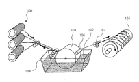
- FIG. 7 shows a schematic conceptual diagram of an example of a tank manufacturing apparatus having a resin bath used in the wet method.
- the manufacturing apparatus shown in FIG. 7 impregnates a supply roll 101 in which a tow of carbon fiber or the like is wound, a resin bath 103 containing a resin 102, a rotary roll 104 rotatably provided in the resin bath 103, and a resin. And a liner 105 for forming a tank.
- Tows supplied from a plurality of supply rolls 101 are guided into the resin bus 103.
- the carbon fibers in the resin bath 103 are impregnated with resin while being guided along the periphery of the rotary roll 104. Excess resin is squeezed out by the resin content adjusting roll 106, and the resin content is adjusted.
- the tow whose resin content has been adjusted is wound around the liner 105 while the winding tension adjusting unit 107 adjusts the tension at the time of winding.
- the resin bath method allows the tow to pass directly through the resin bath, there is a problem that the inside of the resin bath is soiled with fluff and the like.
- the resin accommodated in the resin bath has a low viscosity of, for example, about 0.1 Pa ⁇ s.
- the rotating roll is rotated at a high speed in such a low viscosity resin, the resin is scattered, so that the rotating speed of the rotating roll is limited.
- the tow wrapped around the liner is in a slippery state.
- CFRP carbon fiber reinforced plastic
- molded products manufactured by the wet method such as the resin bath method have low quality stability due to the difficulty of maintaining a constant weight ratio between the fiber and the resin, and damage due to tow friction. In order to prevent this, there are problems such as high manufacturing costs due to low production speed.
- toe prepreg means a fiber bundle impregnated with a resin.
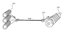
- FIG. 8 shows a schematic conceptual diagram of an example of a tank manufacturing apparatus using a tow prepreg.
- the manufacturing apparatus shown in FIG. 8 includes a supply roll 201 around which a tow prepreg is wound, a winding tension adjusting unit 207, and a liner 205 that forms a tank.
- a method for producing a tow prepreg for example, in Patent Document 1, a matrix resin is supplied to a tow through a nozzle at a constant supply amount, and the tow passing through the nozzle is controlled at a constant speed.
- a production method capable of realizing the uniformity of the amount of resin impregnated into the resin.
- the tow prepreg supplied from the supply roll 201 is already impregnated with resin, the tow prepreg is wound around the liner 205 without passing through the resin bath while the winding tension adjusting unit 207 adjusts the tension at the time of winding. .
- the viscosity of the resin impregnated in the tow prepreg is about 5 to 100 Pa ⁇ s at the supply roll 201.
- the dry method using tow prepreg eliminates the problems of the wet method. That is, according to the dry method, it is possible to increase the accuracy of the amount of the resin contained, and the tow is not damaged due to yarn breakage, fluffing, etc. that occur when the resin is squeezed. In addition, loosening or collapse of winding during FW molding can be prevented. In addition, since no resin bath is used, there is no limitation on productivity improvement due to the contamination of the resin bath and the viscosity of the resin.
- the resin has a higher viscosity than the wet method, so that the resin hardly penetrates between the fibers. Therefore, the adhesion between the fibers is low, and it may be difficult to ensure the strength of the tank.
- the resin of the tow prepreg has a high viscosity, voids (voids) are more easily generated between the laminated tow prepregs than when the resin has a low viscosity.
- heating only from the outside causes the inner fiber to return to room temperature after winding. Since the inside is not sufficiently solidified due to a decrease in temperature, it may be difficult to ensure the strength of the tank.
- an object of the present invention is to provide a manufacturing method and a manufacturing apparatus for a composite container having a desired shape and strength.
- a first method for producing a composite container according to the present invention includes a step of winding a fiber preliminarily impregnated with a thermosetting resin around a liner forming the container to form a fiber layer, By heating from the inside of the liner, the viscosity of the resin impregnated in the fibers wound around the liner is reduced below the viscosity before being wound around the liner, and the viscosity is reduced. And a step of gradually curing the resin of the fiber layer toward the side away from the side close to the surface of the liner by heating from the inside of the liner.
- the temperature T1 of the liner in the step of lowering the viscosity before being wound around the liner is 30 ° C. or higher and 150 ° C. or lower (preferably 30 ° C. or higher and 100 ° C. or lower), and the step of curing the resin.
- the temperature T2 of the liner in is preferably 60 ° C. or higher and 220 ° C. or lower. Further, it is preferable that T1 ⁇ T2.
- a first manufacturing apparatus corresponding to the first manufacturing method includes: a supply unit that supplies fibers pre-impregnated with a thermosetting resin; and the fibers supplied from the supply unit are wound on an outer peripheral surface.
- a controller that controls the temperature of the internal heating unit so that the resin of the fiber layer is cured from the side close to the surface of the liner after the viscosity is reduced.
- the second method for manufacturing a composite container according to the present invention includes a step of winding a fiber preliminarily impregnated with a thermosetting resin around a liner forming the container to form a fiber layer, and heating from the inside of the liner.
- the internal heating temperature when the fiber is wound around the liner is preferably 80 ° C. or higher and 150 ° C. or lower.
- a component having high reactivity and heat generation potential for example, polyfunctional compounds such as polyfunctional glycidylamine, tetraglycidyl-m-xylenediamine, and tetraglycidyl-1,3-bis (bisaminoethyl) cyclohexane can be used as the component to be added.
- a second manufacturing apparatus corresponding to the second manufacturing method includes: a supply unit that supplies fibers pre-impregnated with a thermosetting resin; and the fibers supplied from the supply unit are wound on an outer peripheral surface.
- a liner for forming a fiber layer, an internal heating portion for heating the inside of the liner, and the resin impregnated in the fiber wound around the liner are cured from the side close to the surface of the liner, and this curing is performed.
- a control unit that controls the temperature of the internal heating unit so as to generate heat.
- the viscosity of the resin impregnated in the fiber wound around the liner is made lower than the viscosity before being wound around the liner. Since the resin whose viscosity has been lowered easily penetrates between the fibers, voids are not formed between the fibers, and the adhesion between the fibers is improved. As a result, the strength as a composite container can be increased.
- the resin of the fiber layer can be gradually cured toward the side away from the side close to the surface of the liner. For this reason, since resin can be wound on the hardened
- the second manufacturing method according to the present invention can perform FW molding while curing the resin of the fiber layer, and therefore can suppress excessive heat storage of heat generated during resin curing. Moreover, since FW molding can be performed while gradually storing the heat generated during resin curing, the heat generated during resin curing can be used for resin curing. Therefore, according to the second manufacturing method of the present invention, since the resin impregnated in the fiber is heated and cured simultaneously with the winding of the fiber around the liner, the manufacturing time can be shortened. Moreover, since heat generated by the curing reaction of the resin is used in combination, it is extremely excellent in terms of thermal efficiency. In addition, along with the progress of winding, curing and heat generation are gradually performed toward the side away from the side closer to the surface of the liner, so that the runaway reaction due to heat generation during resin curing can be suppressed.
- the top view of the manufacturing apparatus of the composite container shown as 1st Embodiment of this invention The figure which shows the manufacture flow of the composite container in 1st Embodiment.
- the top view of the manufacturing apparatus of the composite container shown as 2nd Embodiment of this invention Front view AA sectional view of FIG.
- Explanatory diagram of temperature distribution measurement points Schematic conceptual diagram of an example of a tank manufacturing device using a resin bath
- FIG. 1 shows a manufacturing apparatus (FW apparatus) used for manufacturing a composite container as a first embodiment of the present invention.
- the manufacturing apparatus of the present embodiment includes a supply unit 1, a winding tension adjustment unit 2, a speed sensor pulley 3, a delivery eye 4, a liner 5, a driving device 6, an external heating device 7, and an internal heating device 8. And a control unit 9.
- the supply unit 1 is a device that supplies a tow prepreg 11 and includes a plurality of supply rolls 10 around which the tow prepreg 11 is wound.
- the tow prepreg 11 wound around the supply roll 10 is held in a state of maintaining a viscosity of 5 Pa ⁇ s to 100 Pa ⁇ s, preferably 7 Pa ⁇ s to 50 Pa ⁇ s.
- the supply speed of the tow prepreg 11 from the supply unit 1 is controlled by the control unit 9.
- the supply part 1 in this embodiment demonstrates as an example the system by which the already manufactured tow prepreg 11 is supplied in the state wound by the supply roll 10, this invention is not limited to this.
- the supply unit 1 may employ a method in which a tow prepreg is manufactured by supplying resin to the tow and the manufactured tow prepreg is supplied.
- the winding tension adjusting unit 2 and the speed sensor pulley 3 are disposed between the supply unit 1 and the liner 5.
- the winding tension adjusting unit 2 is configured to be able to apply a required winding tension to the tow prepreg 11 wound around the liner 5, and the winding tension applied by the control unit 9 is controlled.
- the speed sensor pulley 3 is a speed sensor that senses the linear speed of the tow prepreg 11.
- the linear velocity of the tow prepreg 11 detected by the velocity sensor pulley 3 is transmitted to the control unit 9 from a signal transmitter (not shown).
- the control unit 9 controls the supply speed of the tow prepreg 11 from the supply unit 1 based on the signal from the signal transmitter.
- the linear velocity of the tow prepreg 11 is constantly measured by the velocity sensor pulley 3 and fed back to the control unit 9 from the signal transmitter in real time. Even when the diameter of the winding molded body from the beginning to the end of winding is changed, the resin supply amount is controlled, and the resin content with respect to the tow is controlled to be constant throughout the FW molding.
- the delivery eye 4 is a device for converging the tow prepreg 11 supplied from the supply unit 1 and winding it around the liner 5 with FW, and is provided so as to be able to reciprocate in a direction parallel to the axial direction of the liner 5.
- the orientation angle of the tow prepreg 11 is determined by the ratio of the rotational speed of the liner 5 and the moving speed of the delivery eye 4.
- the moving speed of the delivery eye 4 is controlled by the control unit 9.
- the liner 5 is a metal hollow cylindrical member, and is rotationally driven by a driving device 6.
- the tow prepreg 11 that has passed through the delivery eye 4 is wound around the outer peripheral surface of the liner 5 by FW.
- the controller 9 controls the drive device 6 that rotationally drives the liner 5.
- the external heating device 7 is a heater that heats the tow prepreg 11 wound around the outer peripheral surface of the liner 5.
- the temperature control of the external heating device 7 is performed by the control unit 9.
- the internal heating device 8 includes a heater 8a and a fluid supply unit 8b, and is connected to the liner 5 via a pipe 8c.
- the internal heating device 8 heats the fluid by the heater 8a, and supplies the heated fluid to the liner 5 through the pipe 8c by the fluid supply unit 8b, thereby heating the toe prepreg 11 from the inside of the liner 5. It is.
- the pipe 8 c is connected to both end portions 5 a of the liner 5 and constitutes a circulation path so that the fluid supplied from the internal heating device 8 to the liner 5 is returned to the internal heating device 8 again. In the present embodiment, air is used as the heating fluid.
- the sealing structure of the connecting portion between the rotationally driven liner 5 and the pipe 8c is simpler than when using a gas other than liquid or air as the heating fluid. It is possible to However, the present invention does not exclude the application of a gas other than liquid or air as a heating fluid.
- a gas other than liquid or air for example, an electric heater or the like can be used as the heater 8a, and a pump, a fan, or the like can be used as the fluid supply unit 8b.
- the fluid temperature in the liner 5 is detected by the temperature sensor 8d.
- the fluid temperature detected by the temperature sensor 8d is transmitted to the control unit 9. Based on the signal transmitted from the temperature sensor 8d, the control unit 9 controls the heater 8a so that the fluid temperature becomes a predetermined temperature.
- the fluid temperature is controlled within a temperature range of about 40 ° C. to 150 ° C., but the temperature control range in the present invention is not limited to this, and the characteristics of the tow prepreg 11 to be applied. It may be appropriately changed depending on the situation.
- the temperature control is described as being performed by controlling the heater 8a.
- the present invention is not limited to this, and for example, the temperature is controlled by the amount of fluid supplied by the fluid supply unit 8b.
- a valve (not shown) may be provided in the middle of the pipe 8c, and the opening of the valve may be adjusted. Control of the opening degree of the fluid supply unit 8b and the valve is also performed by the control unit 9 based on a signal from the temperature sensor 8d.
- the control unit 9 drives and controls the supply unit 1, the winding tension adjusting unit 2, the delivery eye 4, the liner 5, the external heating device 7, the internal heating device 8, and the like as described above.
- the reinforcing fiber of the tow prepreg 11 applicable to the present embodiment is not particularly limited, and specific examples include carbon fiber, glass fiber, alumina fiber, silicon carbide fiber, boron fiber, and aramid fiber, and particularly carbon fiber. Is preferably used. More preferably, carbon fibers that are difficult to be impregnated with resin, have a fiber diameter of 6 ⁇ m or less, and a fineness of 800 g / km or more can be used. Also, the resin impregnated in the tow is not particularly limited, and for example, a thermosetting resin, particularly an epoxy resin is preferable because it is easy to handle.
- the epoxy resin may be a one-component epoxy resin using a latent curing agent, but it is preferable to use a two-component epoxy resin having a lower viscosity while mixing with a static mixer.
- a static mixer By using a static mixer, one of the problems in the conventional wet method can be solved, that is, the resin gradually reacts during winding to increase the viscosity, thus increasing the resin content.
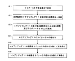
- FIG. 2 is a diagram showing a manufacturing flow of the manufacturing method of the present embodiment.
- inside of the fiber layer means a layer closer to the liner 5 among the layers of the tow prepreg 11 formed by being wound around the liner 5.
- control unit 9 supplies warm air into the liner 5 by the internal heating device 8 and raises the temperature of the liner 5 to a predetermined temperature (step S1).
- the temperature of the liner 5 is controlled within a range of 30 ° C. to 220 ° C.
- the supply unit 1 supplies the tow prepreg 11 having a viscosity of 5 Pa ⁇ s to 100 Pa ⁇ s, preferably 7 Pa ⁇ s to 50 Pa ⁇ s, to the winding tension adjusting unit 2 (step S2). Subsequently, the toe prepreg 11 is focused by being supplied to the delivery eye 4 while adjusting the tension by the winding tension adjusting unit 2 (step S3). Further, the tow prepreg 11 is wound around the liner 5 that is rotationally driven while being reciprocated in the direction parallel to the axial direction of the liner 5 by the delivery eye 4 (step S4).
- the controller 9 controls the temperature of the internal heating device 8 so as to reduce the viscosity of the resin of the tow prepreg 11 wound around the liner 5 by heating the liner 5 from the inside (step S5).
- the outer surface temperature is measured using a thermal image sensor, and the heater 8a is controlled.
- the temperature in the liner 5 at this time is set to 30 ° C. or higher and 150 ° C. or lower, preferably 30 ° C. or higher and 100 ° C. or lower.
- the resin is in a state of high fluidity due to the reduced viscosity. Particularly in the case of this embodiment, since the resin is heated from the inner side of the liner 5 by the internal heating device 8, the winding progresses and the liner advances. The state of high fluidity can be maintained also for the resin in the inner part of the fiber layer formed on 5.
- the resin of the tow prepreg 11 having improved fluidity is in a state of easily penetrating between the tow prepregs 11, air bubbles between the tow prepregs 11 are removed, and adhesion between the tow prepregs 11 is enhanced.
- the control unit 9 controls the temperature of the internal heating device 8 in order to cure the resin of the tow prepreg 11 wound around the liner 5. (Step S6).
- the temperature in the liner 5 is set in the range of 30 ° C. to 220 ° C., preferably 60 ° C. or higher and 180 ° C. or lower, depending on the liner capacity and resin viscosity.
- the inside of the liner 5 is heated with warm air to gradually apply heat from the inside of the fiber layer
- the inside of the fiber layer of the tow prepreg 11 is directed from the inside to the outside (close to the liner 5).
- the resin can be gradually cured (toward the side away from the side).
- this manufacturing method heats a fiber layer from the inside of the liner 5, since the resin of the inner part of a composite container can also fully harden
- the adhesion between the tow prepregs 11 is extremely high, and the resin inside the container is sufficiently cured, so that it has high pressure resistance and suppresses fiber slip. Therefore, a composite container molded into a desired shape can be manufactured.
- FIGS. 3 to 5 show a manufacturing apparatus (FW apparatus) used for manufacturing a composite container as a second embodiment of the present invention.
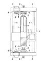
- FIG. 3 is a plan view
- FIG. 4 is a front view
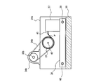
- FIG. It is sectional drawing.
- a cylindrical liner 21 forming a container is horizontally supported between side frames 31a and 31b, and is rotated around its central axis, so that it can move in parallel with the central axis of the liner 21 (
- the fiber F is wound around the outer peripheral surface of the rotating liner 21 by feeding out the fiber F preliminarily impregnated with the thermosetting resin from the supply unit 37.
- the liner 21 is made of metal (for example, aluminum), and both ends of the cylindrical body are rounded into a dome shape to form end plates 22a and 22b. Yes.
- the base portions 23 a and 23 b also serve as a rotation shaft portion when the fiber F is wound while rotating the liner 21.
- the support part of the FW device rises from the base stand 30, a side frame 31 a that rises from one side of the base stand 30 and supports one end side (the base part 23 a side) of the liner 21, and the other side of the base stand 30. And a side frame 31b for supporting the other end side (base portion 23b side) of the liner 21.
- the side frame 31a rotatably supports a chuck portion 32a capable of holding the base portion 23a on one end side of the liner 21 via a bearing portion 33a.
- a motor 34a is disposed above the side frame 31a.
- a belt 36a is wound between the output shaft 35a of the motor 34a and the chuck portion 32a, and the liner 21 can be rotated together with the chuck portion 32a by the motor 34a. It is like that.
- the side frame 31b rotatably supports a chuck portion 32b capable of holding the base portion 23b on the other end side of the liner 21 via a bearing portion 33b.
- a motor 34b is disposed above the side frame 31b.
- a belt 36b is wound between the output shaft 35b of the motor 34b and the chuck portion 32b, and the liner 21 can be rotated together with the chuck portion 32b by the motor 34b. It is like that.
- the mechanism on the side frame 31a side and the mechanism on the side frame 31b side are provided in mirror symmetry with each other, and the liner 21 can be rotated around its central axis at a desired speed by cooperative control of the motors 34a and 34b. it can.
- the feeding device 37 is provided on a carriage (slider) 38.
- the carriage 38 is movable on the base table 30 in the extending direction (that is, the direction parallel to the rotation axis of the liner 21).
- the carriage 38 is guided by two guide members 39, 40 that are passed between the side frames 31a, 31b, and at least one of these guide members 39, 40 is used as a feed screw by a motor (not shown). By rotating, the guide members 39 and 40 are moved in the extending direction.
- the feeding device 37 on the carriage 38 stores therein the fiber F impregnated with a thermosetting resin in advance, and can feed the fiber F from the feeding port 41. Therefore, by winding the starting end of the feeding side of the fiber F around the outer peripheral surface of the liner 1 in advance and rotating the liner 21, the position of the feeding port 41 is reciprocated in the direction of the rotation axis of the liner 21.
- the fiber F can be wound around the entire outer peripheral surface of the.
- the fiber F impregnated with the thermosetting resin fed out from the feeding device 37 in advance may be a tow prepreg or a fiber impregnated by a resin bath method. That is, the fiber pre-impregnated with the thermosetting resin may be a tow prepreg, but may be a fiber impregnated by a resin bath method. This is because it is cured while being wound around the liner, so that it is possible to avoid loose winding or collapse by the wet method.
- the feeding device 37 includes a reel (not shown) in which the tow prepreg is wound in a roll shape, and the tow prepreg may be fed from the reel through the feeding port 41.
- the feeding device 37 includes a reel (not shown) in which the fibers before impregnation are wound in a roll shape, and a resin bath (not shown) through which the fiber fed from the reel passes. And the fiber impregnated with the resin by passing through the resin bath may be fed out through the outlet 41.
- the liner 21 supported between the side frames 31a and 31b and made rotatable is provided with a rod-shaped heater (internal heating portion) 42 along the central axis (rotation center) from the openings of the cap portions 23a and 23b at both ends. Arrange. Then, both end portions of the heater 42 are passed through the side frames 31a and 31b, and are held by holding portions 43a and 43b that also serve as electrode portions fixed to these outer surfaces. Then, the heater 42 is energized through the holding portions (electrode portions) 43a and 43b so that it can be heated from the inside of the liner 21.
- the heater 42 is controlled by a control unit (not shown) (similar to the control unit 9 in FIG. 1). In the present embodiment, the heater 42 is not rotated with the liner 21, but may be rotated with the liner 21.
- the fiber layer is thickened to increase its strength. Therefore, when the resin is cured after FW molding, heat generated during resin curing is accumulated in the fiber layer, causing reaction runaway. There are concerns. Therefore, in order to form a thick fiber layer, it is necessary to take a method such as FW molding and curing to a thickness that does not accumulate curing reaction heat generation, and then FW molding again. It will be extended.
- Patent Document 1 when a fiber layer is formed by winding fibers impregnated with a thermosetting resin around a liner forming a container, the fibers are wound around the outer peripheral surface of the liner while heating the liner from the inside. It has been proposed to gradually cure the resin by attaching. According to this, since the resin impregnated in the fiber can be heated to accelerate the curing simultaneously with the winding of the fiber around the liner, the time required for the production can be greatly reduced.
- the fiber layer is formed by winding the fiber F preliminarily impregnated with the thermosetting resin on the liner 1
- the resin is heated simultaneously with the FW molding by heating from the inside of the liner 1. Since it can be cured and a curing process after FW molding is not required, the manufacturing time can be shortened.
- the resin impregnated in the fiber F wound around the liner 1 can be gradually cured toward the side away from the side close to the surface of the liner 1. Along with this, heat generation due to the curing reaction gradually proceeds toward the side away from the side close to the surface of the liner 1. Therefore, heat generated during resin curing is not accumulated at a stretch, and reaction runaway due to heat generated during resin curing can be suppressed.
- the heat generation at the time of resin curing can be increased, and the heat generation can be used for resin curing, enabling more efficient production. It becomes.
- blending a polyfunctional resin in the resin blend is effective because heat generation during resin curing is increased.
- Example 1 corresponds to the first embodiment
- Example 2 corresponds to the second embodiment.
- Example 1-1 In Example 1-1, a cylindrical tube was manufactured by the method for manufacturing a composite container of the present invention under the following conditions, and its burst strength was measured.
- the resin to be impregnated with tow is 80 parts by weight of bisphenol A type epoxy resin, 20 parts by weight of bisphenol F type epoxy resin, 18 parts by weight of dicyandiamide (DICY), and 3- (3,4-dichlorophenyl) -1,1-dimethylurea.
- a resin composition in which 9 parts by weight of (DCMU) was mixed was used.
- the viscosity of this resin composition was 7 Pa ⁇ s at 25 ° C. and 0.1 Pa ⁇ s at 80 ° C.
- This resin composition was impregnated into 24000 filaments of carbon fiber T800SC manufactured by Toray Industries, Inc. and wound on a bobbin to obtain a tow prepreg having a resin content of 29%.
- the above-mentioned tow prepreg was filament wound (FW) into an aluminum cylindrical tube having an outer diameter of 99 mm and an inner diameter of 95 mm in the center portion.
- the FW conditions were a helical winding with a rotation speed of 200 rpm and a tension of 50 N, and an internal heating temperature of 80 ° C.
- the internal heating temperature was set to 130 ° C. after the FW was completed, and the mixture was held for 2 hours and then allowed to cool.
- the burst pressure was 120 MPa.
- Example 1-2 a cylindrical tube was manufactured by the method for manufacturing a composite container of the present invention under the following conditions, and its burst strength was measured.
- a resin composition in which 80 parts by weight of a bisphenol A type epoxy resin, 20 parts by weight of a phenolvolak type epoxy resin, 18 parts by weight of dicyandiamide (DICY) and 9 parts by weight of DCMU were used.
- the viscosity of this resin composition was 50 Pa ⁇ s at 25 ° C. and 0.2 Pa ⁇ s at 80 ° C.
- This resin composition was impregnated into 24000 filaments of carbon fiber T800SC manufactured by Toray Industries, Inc. and wound on a bobbin to obtain a tow prepreg having a resin content of 28%.
- the above-mentioned tow prepreg was filament wound (FW) into an aluminum cylindrical tube having an outer diameter of 99 mm and an inner diameter of 95 mm in the center portion.
- the FW conditions were a helical winding with a rotation speed of 200 rpm and a tension of 50 N, and an internal heating temperature of 80 ° C.
- the bobbin of the tow prepreg was kept warm at about 40 ° C. with an infrared lamp in advance, and the instantaneous temperature change during winding was alleviated.
- the internal heating temperature was set to 130 ° C. after the FW was completed, and the mixture was held for 2 hours and then allowed to cool.
- the burst pressure was 125 MPa.
- Example 1-3 a cylindrical tube was manufactured by the method for manufacturing a composite container of the present invention under the following conditions, and its burst strength was measured.
- Example 1-3 Tow Prepreg T800S-24-RC27-SY2 manufactured by Nippon Oil Corporation was filament wound (FW) into an aluminum cylindrical tube having an outer diameter of 99 mm and an inner diameter of 95 mm at the center.
- the FW conditions were a helical winding with a rotation speed of 200 rpm and a tension of 50 N, and an internal heating temperature of 80 ° C.
- the internal heating temperature was set to 130 ° C. after the FW was completed, and the mixture was held for 2 hours and then allowed to cool.
- the burst pressure was 129 MPa.
- Comparative Example 1-1 In Comparative Example 1-1, a cylindrical tube was manufactured without performing internal heating under the following conditions, and its burst strength was measured.
- Comparative Example 1-1 the same tow prepreg as in Example 1-1 was used, and FW was performed on the cylindrical tube under the same conditions except for the temperature conditions.
- internal heating was not performed, FW was performed at room temperature, and for resin curing, the internal heating temperature was set to 130 ° C. for 2 hours after cooling, and then cooled.
- the burst pressure was 100 MPa.
- Comparative Example 1-2 a cylindrical tube was manufactured by the wet method under the following conditions, and its burst strength was measured.
- Comparative Example 1-2 4 parts by weight of a commercially available diluted epoxy resin (trade name: Epicoat 801P, manufactured by Japan Epoxy Resin Co., Ltd.) and a commercially available imidazole curing agent (trade name: EMI24, manufactured by Japan Epoxy Resin Co., Ltd.) ) A resin composition mixed with 4 parts by weight was used. The viscosity of this resin composition was 1 Pa ⁇ s at 25 ° C. and 0.02 Pa ⁇ s at 80 ° C. In this comparative example, this resin composition was used as a wet resin.
- a commercially available diluted epoxy resin (trade name: Epicoat 801P, manufactured by Japan Epoxy Resin Co., Ltd.) and a commercially available imidazole curing agent (trade name: EMI24, manufactured by Japan Epoxy Resin Co., Ltd.)
- EMI24 commercially available imidazole curing agent
- the burst pressure was 110 MPa.
- Example 2-1 a cylindrical tube was manufactured by the method for manufacturing a composite container of the present invention under the following conditions, and the temperature distribution in the thickness direction of the CFRP layer was measured.
- Examples of the resin impregnated in the tow prepreg used in Example 2-1 include 50 parts by weight of bisphenol A type epoxy resin, 50 parts by weight of bisphenol F type epoxy resin, 18 parts by weight of dicyandiamide (DICY), and 3- A composition in which 9 parts by weight of (3,4-dichlorophenyl) -1,1-dimethylurea (DCMU) was mixed was used.
- This composition was impregnated with 24000 filaments of carbon fiber T800SC manufactured by Toray Industries, Inc., wound on a bobbin, and made into a tow prepreg with a resin content of 29%.
- the above-mentioned tow prepreg was filament wound (FW) into an aluminum cylindrical tube having an outer diameter of 113 mm and an inner diameter of 95 mm in the central portion.
- the FW conditions were fixed at a rotation speed of 15 rpm and a tension of 20 N hoop winding (CFRP layer thickness 60 mm), and the internal heating conditions were fixed so that the liner surface temperature at the start of FW was 135 ° C.
- a thermocouple was inserted into the FW with a CFRP layer thickness of 10 mm, and the temperature in the CFRP layer thickness direction was observed in detail.
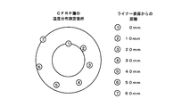
- FIG. 6 shows the insertion position of the thermocouple.
- Example 2-2 a cylindrical tube was manufactured under the same conditions as in Example 2-1, and the temperature distribution in the thickness direction of the CFRP layer at that time was measured.
- Example 2-2 As the resin impregnated in the tow prepreg used in Example 2-2, 50 parts by weight of bisphenol A type epoxy resin, 30 parts by weight of bisphenol F type epoxy resin, 20 parts by weight of polyfunctional glycidylamine, dicyandiamide (DICY) ) 18 parts by weight and 3- (3,4-dichlorophenyl) -1,1-dimethylurea (DCMU) 9 parts by weight were used.
- This composition was impregnated with 24000 filaments of carbon fiber T800SC manufactured by Toray Industries, Inc., wound on a bobbin, and made into a tow prepreg with a resin content of 29%.
- the above-mentioned tow prepreg was filament wound (FW) into an aluminum cylindrical tube having an outer diameter of 113 mm and an inner diameter of 95 mm in the central portion.
- the FW conditions were fixed at a rotation speed of 15 rpm and a tension of 20 N hoop winding (CFRP layer thickness 60 mm), and the internal heating conditions were fixed so that the liner surface temperature at the start of FW was 135 ° C.
- a thermocouple was inserted into the FW with a CFRP layer thickness of 10 mm, and the temperature in the CFRP layer thickness direction was observed in detail.
- Example 2-3 In Example 2-3, a cylindrical tube was manufactured by the resin bath method under the same conditions as in Example 2-1, and the temperature distribution in the thickness direction of the CFRP layer at that time was measured.
- Examples of the resin impregnated in the carbon fiber used in Example 2-3 include 80 parts by weight of bisphenol A type epoxy resin, 20 parts by weight of tetraglycidyl-m-xylenediamine, 18 parts by weight of dicyandiamide (DICY), and A composition in which 9 parts by weight of 3- (3,4-dichlorophenyl) -1,1-dimethylurea (DCMU) was mixed was used. This composition was put into a resin bath. A 24000 filament of carbon fiber T800SC manufactured by Toray Industries, Inc. was used.
- Filament winding (FW) by the resin bath method was performed on an aluminum cylindrical tube having an outer diameter of 113 mm and an inner diameter of 95 mm in the central portion.
- the FW conditions were fixed at a rotation speed of 15 rpm and a tension of 20 N hoop winding (CFRP layer thickness 60 mm), and the internal heating conditions were fixed so that the liner surface temperature at the start of FW was 135 ° C.
- a thermocouple was inserted into the FW with a CFRP layer thickness of 10 mm, and the temperature in the CFRP layer thickness direction was observed in detail.
- Comparative Example 2-1 a cylindrical tube was produced without performing internal heating under the following conditions, and cured in a heating furnace for resin curing. That is, in Comparative Example 2-1, the same tow prepreg as in Example 2-1 was used, and FW was performed on the cylindrical tube under the same conditions except for the internal heating conditions. And it hardened
- the hot air was sent to the cylindrical tube having the CFRP layer cured here so that the liner temperature was 135 ° C. and the temperature distribution measurement in the thickness direction of the CFRP layer was performed, the column of Comparative Example 2-1 in Table 1 was obtained. It came to show in.
- Comparative Example 2-2 a temperature distribution was measured when a cylindrical tube was produced without internal heating and cured in a heating furnace for resin curing under the following conditions.
- Comparative Example 2-2 the same toe prepreg as in Example 2-1 was used, and FW was performed on the cylindrical tube under the same conditions except for the internal heating conditions.
- FW was performed on the cylindrical tube under the same conditions except for the internal heating conditions.
- since hardening by FW internal heating was not performed after completion of FW, it was heated from room temperature to 130 ° C. at a temperature rising rate of 2 ° C./min, held for 2 hours, and then allowed to cool.
- the temperature distribution in the thickness direction of the CFRP layer at that time was measured, it was as shown in the column of Comparative Example 2-2 in Table 1.
- Comparative Example 2-1 shows the temperature distribution when the resin-cured cylindrical tube is heated from the inside of the liner. Compared with Examples 2-1 to 2-3, the heat generation during resin curing is shown. The temperature is low because there is no. Therefore, in comparison with Comparative Example 2-1, it can be seen that in Examples 2-1 to 2-3, the heat generated during resin curing can be used effectively.
- Example 2-2 and 2-3 compared to Example 2-1, a multifunctional resin (polyfunctional glycidylamine in Example 2-2, By using tetraglycidyl-m-xylenediamine 20), the temperature increases by 2 to 5 ° C. at each position, and it can be seen that the heat generated during resin curing can be used more effectively.
- Comparative Example 2-2 is a case where heat curing is performed after FW molding, and it can be seen that the heat generated during resin curing is accumulated in the fiber layer, resulting in an extremely high temperature. Therefore, in comparison with Comparative Example 2-2, it can be seen that in Examples 2-1 to 2-3, excessive heat generation during resin curing is suppressed.
- the present invention can efficiently produce a composite container having a desired shape and strength, and has great industrial applicability.
Landscapes
- Engineering & Computer Science (AREA)
- Manufacturing & Machinery (AREA)
- Mechanical Engineering (AREA)
- General Engineering & Computer Science (AREA)
- Moulding By Coating Moulds (AREA)
Abstract
所望の形状及び強度を有する複合容器の製造方法を提供する。 トウプリプレグをライナーに巻付けて繊維層を形成し(S4)、ライナーの内部から加熱して、ライナーに巻付けられた繊維に含浸されている樹脂の粘度を、ライナーに巻付ける前の粘度よりも低下させ(S5)、この後、ライナーの内部から加熱して、繊維層の樹脂をライナーの表面に近い側から離れる側に向けて徐々に硬化させる(S6)。 又は、トウプリプレグをライナーに巻付けて繊維層を形成し、ライナーの内部から加熱することで、ライナーに巻付けられた繊維に含浸されている樹脂をライナーの表面に近い側から離れる側に向けて徐々に硬化させ、この硬化に伴って樹脂を発熱させる。
Description
本発明は、高圧流体(気体あるいは液体)を収納するために容器(タンク等)を形作るライナーをこれに巻装される複合材料により強化した複合容器の製造方法及び製造装置に関する。
従来、ガラス繊維、炭素繊維、芳香族ポリアミド繊維等を強化材とし、エポキシ樹脂、不飽和ポリエステル樹脂、ビニルエステル樹脂等をマトリックス樹脂とした複合材料は、スポーツ用品、自動車部品を始め広く使用されている。
複合材料の製造方法には、繊維強化材に未硬化のマトリックス樹脂を含浸させてプリプレグとし、該プリプレグを成形硬化させる方法が広く採用されている。一方で、フィラメントワインディング(FW)による中空物の成形方法、いわゆるFW法も、複合材料の製造方法として多く採用されている。
FW法には、予め熱硬化性樹脂マトリックスを含浸したストランドプリプレグを用意し、これをマンドレルに巻付けて成形する方法(ドライFW法)と、ストランドに低粘度樹脂を含浸させながら、マンドレルに巻付けて成形する方法(ウエットFW法)とがあることは広く知られている。更にこのウエットFW法は、ストランドに低粘度樹脂を含浸させる方法の種類によって、キスタッチ法、浸漬法その他の方法に分類されている。
FW法における現在の主流は、液状の樹脂を用いる、レジンバス法等のいわゆるウエット法である。
図7にウエット法に用いられるレジンバスを有するタンク製造装置の一例の模式的な概念図を示す。
図7に示す製造装置は、炭素繊維等のトウを巻回した供給ロール101と、樹脂102を収納したレジンバス103と、レジンバス103内に回転可能に設けられた回転ロール104と、樹脂を含浸させたトウを巻取り、タンクを成形するライナー105とを有する。複数の供給ロール101から供給されたトウはレジンバス103内へと案内される。レジンバス103内の炭素繊維は回転ロール104の周縁を案内されながら樹脂が含浸される。樹脂含有量調整ロール106によって余剰の樹脂が搾り取られ、樹脂含有量の調整がなされる。樹脂含有量の調整がなされたトウは、巻付張力調整部107により巻付け時の張力が調整されながら、ライナー105に巻付けられる。
レジンバス法は、トウをレジンバス内に通過させて樹脂含浸させた後、樹脂含有量調整ロールによって余剰の樹脂を搾り取り樹脂含有量を調整する際、トウとの摩擦が生じ、糸切れ、毛羽立ち等を伴うトウの損傷が生じる。また樹脂を搾り取ることによって樹脂含有量を調整するため、樹脂含有量を高精度で調整するのが困難である。
また、レジンバス法は、レジンバス内に直接トウを通過させるので、レジンバス内が毛羽等で汚損してしまう問題がある。
さらに、レジンバス内に収納されている樹脂は、例えば、0.1Pa・s程度の低粘度のものである。このような低粘度の樹脂内で回転ロールを高速回転させると樹脂が飛散してしまうため、回転ロールの回転速度は制限を受けてしまう。
また、低粘度の樹脂を用いることから、ライナーに巻付けられたトウが滑りやすい状態にある。特に、厚みのある繊維層、例えばCFRP(炭素繊維強化プラスチック)を形成しようとすると、炭素繊維の巻き緩みや巻き崩れが生じてしまう。
このため、レジンバス法等のウエット法は、成形品の形状を所望の形状にすべく、装置を一旦停止して樹脂を固め、固化されたら再度装置を駆動する、といった制御を繰り返す必要がある。これらが原因でウエット法は生産性を向上させるのが困難となる。
また、レジンバス法等のウエット法では、反応性の高い樹脂を用いることが多く、このため室温で徐々に硬化反応が進行し、ワインディング中に樹脂粘度が増加する傾向がある。このような粘度変化は樹脂のピックアップ量に影響するため、結果として樹脂含有量の均一化が損なわれることになる。
このように、レジンバス法等のウエット法により製造された成形品は、繊維と樹脂との重量比を精度良く一定にすることが困難であることによる品質安定性の低さ、トウの摩擦による損傷を防ぐために生産速度が低いことによる製造コストの高さ等の問題がある。
そこで、予め樹脂が含浸されたトウプリプレグを用いてFW成形を行う、いわゆるドライ法が用いられることがある。ここで、「トウプリプレグ」とは、繊維束に樹脂を含浸させたものを意味する。
図8にトウプリプレグを用いたタンク製造装置の一例の模式的な概念図を示す。
図8に示す製造装置は、トウプリプレグを巻回した供給ロール201と、巻付張力調整部207と、タンクを成形するライナー205とを有する。尚、トウプリプレグの製造法としては、例えば特許文献1において、ノズルを介してマトリックス樹脂を一定の供給量でトウに供給し、かつ該ノズルを通過するトウを一定速度に制御することにより、トウへの樹脂含浸量の均一性を実現しうる製造法が提案されている。
図8に示す製造装置は、トウプリプレグを巻回した供給ロール201と、巻付張力調整部207と、タンクを成形するライナー205とを有する。尚、トウプリプレグの製造法としては、例えば特許文献1において、ノズルを介してマトリックス樹脂を一定の供給量でトウに供給し、かつ該ノズルを通過するトウを一定速度に制御することにより、トウへの樹脂含浸量の均一性を実現しうる製造法が提案されている。
供給ロール201から供給されたトウプリプレグは、すでに樹脂が含浸されているため、レジンバスを通過することなく、巻付張力調整部207により巻付け時の張力が調整されながら、ライナー205に巻付けられる。ライナー205へのトウプリプレグの巻付け時に、ライナー205外部からトウプリプレグを加熱することでトウプリプレグを硬化させる方法もある。尚、トウプリプレグに含浸されている樹脂の粘度は供給ロール201部分で5~100Pa・s程度である。
トウプリプレグを用いたドライ法によれば、ウエット法の問題点が解消される。すなわち、ドライ法によれば、含有樹脂量の高精度化が可能であり、樹脂を搾り取る際に生じる糸切れ、毛羽立ち等を伴うトウの損傷を生じることもない。また、FW成形中の巻き緩みや巻き崩れを防ぐことができる。また、レジンバスを用いないので、レジンバスの汚損、樹脂の粘度に起因する生産性向上の制限もない。
しかしながら、トウプリプレグを用いたドライ法によりタンクを製造する場合、比較的樹脂粘度が高いことからFW時に繊維が浸透しにくい、という問題があった。
また、ドライ法においては、樹脂の粘度がウエット法に比べ高いため、樹脂が繊維間に浸透しにくい。そのため、繊維間の密着性が低く、タンクの強度を確保するのが困難となる場合があった。また、トウプリプレグは、樹脂が高粘度であるため、積層されたトウプリプレグ間には樹脂が低粘度の場合より空隙(ボイド)が生じ易い。
また、外側からの加熱のみでは、巻付け後、内側の繊維が室温に戻ってしまう。温度が低下することで内側を十分に固化しにくいため、タンクの強度を確保するのが困難となる場合があった。
さらに、外部のみから加熱するドライ法においては、繊維の巻量が多くなると、内側に巻かれた樹脂が硬化する前に繊維が重ねて巻かれてしまうことになる。そのため、繊維間に滑りを生じてしまい、所望の形状のタンクを形成するのが困難となる場合があった。
本発明は、このような実状に鑑み、所望の形状及び強度を有する複合容器の製造方法及び製造装置を提供することを課題とする。
上記課題を解決するため、本発明に係る複合容器の第1の製造方法は、容器を形作るライナーに熱硬化性の樹脂が予め含浸された繊維を巻付けて繊維層を形成する工程と、前記ライナーの内部から加熱することで、前記ライナーに巻付けられた前記繊維に含浸されている前記樹脂の粘度を、前記ライナーに巻付ける前の粘度よりも低下させる工程と、前記粘度を低下させた後、前記ライナーの内部から加熱することで、前記繊維層の前記樹脂を前記ライナーの表面に近い側から離れる側に向けて徐々に硬化させる工程と、を含むものとする。
ここで、前記ライナーに巻付ける前の粘度よりも低下させる工程における前記ライナーの温度T1は、30℃以上、150℃以下(好ましくは、30℃以上、100℃以下)、前記樹脂を硬化させる工程における前記ライナーの温度T2は、60℃以上、220℃以下であるとよい。また、T1<T2であるとよい。
前記第1の製造方法に対応する第1の製造装置は、熱硬化性の樹脂が予め含浸された繊維を供給する供給部と、前記供給部から供給された前記繊維を巻取り、外周面に繊維層を形成させるライナーと、前記ライナーの内部を加熱する内部加熱部と、前記ライナーに巻付けられた前記繊維に含浸されている前記樹脂の粘度を、前記ライナーに巻付ける前の粘度よりも低下させ、かつ前記粘度を低下させた後、前記繊維層の前記樹脂を前記ライナーの表面に近い側から硬化させるように、前記内部加熱部の温度制御を行う制御部と、を含んで構成される。
また、本発明に係る複合容器の第2の製造方法は、容器を形作るライナーに熱硬化性の樹脂が予め含浸された繊維を巻付けて繊維層を形成する工程と、前記ライナーの内部から加熱することで、前記ライナーに巻付けられた前記繊維に含浸されている前記樹脂を前記ライナーの表面に近い側から離れる側に向けて徐々に硬化させ、この硬化に伴って前記樹脂を発熱させる工程と、を含むものとする。
ここで、前記ライナーに前記繊維を巻付ける際の内部加熱温度は、80℃以上、150℃以下であるとよい。
また、樹脂硬化時の発熱を有効に利用するため、ここで用いる樹脂配合物には、高い反応性や発熱のポテンシャルを有する成分を添加すると好ましい。例えば、添加する成分として、多官能グリシジルアミン、テトラグリシジル-m-キシレンジアミン、及び、テトラグリシジル-1、3-ビス(ビスアミノエチル)シクロヘキサンなどの多官能性化合物を用いることができる。
また、樹脂硬化時の発熱を有効に利用するため、ここで用いる樹脂配合物には、高い反応性や発熱のポテンシャルを有する成分を添加すると好ましい。例えば、添加する成分として、多官能グリシジルアミン、テトラグリシジル-m-キシレンジアミン、及び、テトラグリシジル-1、3-ビス(ビスアミノエチル)シクロヘキサンなどの多官能性化合物を用いることができる。
前記第2の製造方法に対応する第2の製造装置は、熱硬化性の樹脂が予め含浸された繊維を供給する供給部と、前記供給部から供給された前記繊維を巻取り、外周面に繊維層を形成させるライナーと、前記ライナーの内部を加熱する内部加熱部と、前記ライナーに巻付けられた前記繊維に含浸されている前記樹脂を前記ライナーの表面に近い側から硬化させ、この硬化に伴って発熱するように、前記内部加熱部の温度制御を行う制御部と、を含んで構成される。
本発明に係る第1の製造方法は、ライナーの内部から加熱するため、ライナーに巻付けられた繊維に含浸されている樹脂の粘度をライナーに巻付ける前の粘度よりも低下させている。粘度が低下した樹脂は、繊維間に樹脂が浸透しやくなるので繊維間に空隙が形成されず、繊維同士の密着性が向上し、その結果、複合容器としての強度を高めることができる。
また、本発明に係る第1の製造方法は、ライナーの内部から加熱するため、繊維層の樹脂をライナーの表面に近い側から離れる側に向けて徐々に硬化させることができる。このため、硬化した繊維の上に樹脂を巻付けていくことができるので繊維間における滑りを抑制できることとなり、その結果、複合容器を所望の形状に形成することができる。また、本製造方法は、ライナーの内部から加熱するため、複合容器の内側部分の樹脂も十分に硬化することができるので、複合容器としての強度を高めることができる。
本発明に係る第2の製造方法は、繊維層の樹脂を硬化させながらFW成形ができるため、樹脂硬化時の発熱の過度な蓄熱を抑制することができる。また、樹脂硬化時の発熱を徐々に蓄えながらFW成形が実施できるため、樹脂硬化時の発熱を樹脂硬化に利用できる。
従って、本発明に係る第2の製造方法によれば、ライナーへの繊維の巻付けと同時に、繊維に含浸された樹脂を加熱して硬化させるため、製造時間の短縮化が可能となる。また、樹脂の硬化反応により発生する熱を併用するため、熱効率の面で極めて優れる。また、巻付けの進行と合わせ、ライナーの表面に近い側から離れる側に向けて徐々に硬化・発熱させるため、樹脂硬化時の発熱による反応の暴走を抑制することができる。
従って、本発明に係る第2の製造方法によれば、ライナーへの繊維の巻付けと同時に、繊維に含浸された樹脂を加熱して硬化させるため、製造時間の短縮化が可能となる。また、樹脂の硬化反応により発生する熱を併用するため、熱効率の面で極めて優れる。また、巻付けの進行と合わせ、ライナーの表面に近い側から離れる側に向けて徐々に硬化・発熱させるため、樹脂硬化時の発熱による反応の暴走を抑制することができる。
以下に本発明の実施の形態について詳細に説明する。
先ず、本発明の第1実施形態について、図1に基づいて、説明する。
図1は、本発明の第1実施形態として複合容器の製造に用いる製造装置(FW装置)を示している。
先ず、本発明の第1実施形態について、図1に基づいて、説明する。
図1は、本発明の第1実施形態として複合容器の製造に用いる製造装置(FW装置)を示している。
本実施形態の製造装置は、供給部1と、巻付張力調整部2と、速度センサプーリ3と、デリバリーアイ4と、ライナー5と、駆動装置6と、外部加熱装置7と、内部加熱装置8と、制御部9とを有する。
供給部1は、トウプリプレグ11を供給する装置であり、トウプリプレグ11が巻回された複数の供給ロール10を有する。供給ロール10に巻回されたトウプリプレグ11は5Pa・s~100Pa・s、好ましくは7Pa・s~50Pa・sの粘度を維持した状態で保持されている。供給部1からのトウプリプレグ11の供給速度は制御部9により制御される。尚、本実施形態における供給部1は、すでに製造されたトウプリプレグ11が供給ロール10に巻回された状態で供給される方式を例に説明するが、本発明はこれに限定されるものではなく、例えば、供給部1において、トウに樹脂供給してトウプリプレグを製造し、この製造されたトウプリプレグを供給する方式を採用してもよい。
巻付張力調整部2及び速度センサプーリ3は、供給部1とライナー5との間に配置されている。巻付張力調整部2は、ライナー5に巻付けるトウプリプレグ11に所要の巻付張力を付与することができるように構成されており、制御部9によって付与する巻付張力が制御される。速度センサプーリ3は、トウプリプレグ11の線速度を感知する速度センサである。速度センサプーリ3で検出されたトウプリプレグ11の線速度は、不図示の信号送信器から制御部9に送信される。制御部9は、信号送信器からの信号に基づき、供給部1からのトウプリプレグ11の供給速度を制御する。すなわち、トウプリプレグ11の線速度は、速度センサプーリ3により常時測定され、リアルタイムで信号送信器から制御部9にフィードバックされるため、例えば、デリバリーアイ4の折り返し時に速度が低下した際も、あるいは巻始めから巻終わりまでにおけるワインディング成形体の径が変化した場合でも、樹脂供給量が制御され、トウに対する樹脂含有量は終始一定に制御されてFW成形が実施される。
デリバリーアイ4は、供給部1から供給されたトウプリプレグ11を集束させ、FWでライナー5に巻付ける装置であり、ライナー5の軸方向と平行な方向に往復移動可能に設けられている。トウプリプレグ11の配向角度は、ライナー5の回転速度とデリバリーアイ4の移動速度の比により決定される。デリバリーアイ4の移動速度は制御部9により制御される。
ライナー5は、金属製の中空円筒部材であり、駆動装置6により回転駆動される。デリバリーアイ4を通過してきたトウプリプレグ11はライナー5の外周面にFWで巻回される。ライナー5を回転駆動する駆動装置6の制御は制御部9によりなされる。
外部加熱装置7は、ライナー5の外周面に巻回されたトウプリプレグ11を加熱するヒータである。外部加熱装置7の温度制御は、制御部9によりなされる。
内部加熱装置8は、ヒータ8aと、流体供給部8bとを有し、配管8cを介してライナー5に接続されている。内部加熱装置8はヒータ8aにより流体を加熱し、加熱された流体を流体供給部8bにより配管8cを介してライナー5内に供給することでライナー5の内側からトウプリプレグ11を加熱するための装置である。配管8cは、ライナー5の両端部5aに接続されており、内部加熱装置8からライナー5に供給された流体が再び内部加熱装置8に戻されるように循環経路を構成している。本実施形態では、加熱用の流体として空気が用いられている。加熱用の流体として空気を用いることで、回転駆動されるライナー5と配管8cとの接続部分のシール構造を、加熱用の流体として液体や空気以外の他の気体を用いた場合に比べ、簡素化することが可能である。もっとも、本発明は、加熱用の流体として液体や空気以外の他の気体の適用を排除するものではない。ヒータ8aとしては、例えば電熱ヒータ等を用いることができ、流体供給部8bとしては、例えばポンプ、ファン等を用いることができる。
ライナー5内の流体温度は温度センサ8dにより検知される。温度センサ8dで検知した流体温度は制御部9に送信される。制御部9は、温度センサ8dから送信されてきた信号に基づき、流体温度が所定の温度となるようにヒータ8aを制御する。本実施形態においては、流体温度は、約40℃~150℃の温度範囲内で制御されるが、本発明における温度制御範囲はこれに限定されるものではなく、適用されるトウプリプレグ11の特性に応じて適宜変更されるものであってもよい。
また、本実施形態では、温度制御をヒータ8aの制御により行うものとして説明するが、本発明はこれに限定されるものではなく、例えば、流体供給部8bによる流体の供給量により制御するものであってもよいし、あるいは配管8cの途中に不図示の弁を設け、この弁の開度を調整することにより行うものであってもよい。これら流体供給部8b及び弁の開度の制御も温度センサ8dからの信号に基づき制御部9により行われる。
制御部9は、上述したように、供給部1、巻付張力調整部2、デリバリーアイ4、ライナー5、外部加熱装置7及び内部加熱装置8等を駆動制御する。
本実施形態に適用可能なトウプリプレグ11の強化繊維は特に限定されず、例えば、炭素繊維、ガラス繊維、アルミナ繊維、炭化珪素繊維、ボロン繊維、アラミド繊維等が具体的に挙げられ、特に炭素繊維が好ましく用いられる。更に好ましくは、樹脂が含浸し難い、繊維径が6μm以下でかつ繊度が800g/km以上の炭素繊維が挙げられる。また、トウに含浸される樹脂も特に限定されず、例えば、熱硬化性の樹脂、特にエポキシ樹脂が取扱い易いので好ましく挙げられる。エポキシ樹脂としては、潜在型硬化剤を用いた1液型のエポキシ樹脂でもよいが、より低粘度の2液型エポキシ樹脂をスタティックミキサにより混合しながら用いることが好ましい。スタティックミキサの使用により、従来のウエット法における問題点の1つであった、ワインディング中に樹脂が徐々に反応して粘度が上昇し、従って樹脂含有量が増加してしまうという問題が解決できる。
次に、図2を用いて本実施形態に係る複合容器の製造方法について説明する。図2は、本実施形態の製造方法の製造フローを示す図である。尚、以下の説明において「繊維層の内側」とは、ライナー5に巻付けられて形成されたトウプリプレグ11の層のうち、ライナー5に近い側の層を意味する。
先ず、制御部9は、内部加熱装置8により温風をライナー5内へと供給し、ライナー5を所定の温度まで昇温させておく(ステップS1)。尚、本実施形態の場合、ライナー5は、30℃~220℃の範囲内で温度制御がなされる。
次に、供給部1は、5Pa・s~100Pa・s、好ましくは7Pa・s~50Pa・sの粘度のトウプリプレグ11を巻付張力調整部2へ供給する(ステップS2)。続いて、トウプリプレグ11は巻付張力調整部2により張力を調整されながらデリバリーアイ4へと供給されることで集束される(ステップS3)。さらに、トウプリプレグ11は、デリバリーアイ4でライナー5の軸方向と平行な方向に往復移動させられつつ、回転駆動されているライナー5に巻付けられる(ステップS4)。
制御部9は、ライナー5に巻付けられたトウプリプレグ11の樹脂を、ライナー5を内部から加熱することで低粘度化させるべく、内部加熱装置8を温度制御する(ステップS5)。例えば、加熱温度の制御については、熱画像センサを用いて、外表面温度を測定し、ヒータ8aを制御する。尚、このときのライナー5内の温度は、30℃以上、150℃以下、好ましくは、30℃以上、100℃以下に設定しておく。
樹脂は、低粘度化されることで流動性が高い状態となるが、特に本実施形態の場合、内部加熱装置8によりライナー5の内側から加熱しているため、巻付けが進行することでライナー5上に形成された繊維層の内側部分の樹脂についても流動性の高い状態を維持することができる。流動性が高くなったトウプリプレグ11の樹脂は、トウプリプレグ11間に浸透しやすい状態となり、トウプリプレグ11間の気泡が除去されると共にトウプリプレグ11同士の密着性が高められる。
巻付けが進行することでライナー5上に繊維層が形成されていくと、制御部9は、ライナー5に巻付けられたトウプリプレグ11の樹脂を硬化させるべく、内部加熱装置8を温度制御する(ステップS6)。本実施形態の場合、ライナーの容量と樹脂の粘度によってライナー5内の温度を30℃~220℃の範囲内、好ましくは、60℃以上、180℃以下となるように設定しておく。
本実施形態の製造方法は、ライナー5の内部を温風で加熱することで繊維層の内側から徐々に熱を加えるため、トウプリプレグ11の繊維層の内側から外側に向けて(ライナー5に近い側から離れていく側に向けて)徐々に樹脂を硬化させていくことができる。繊維層の内側部分から樹脂を確実に硬化させることで、巻量が多くなったときのトウプリプレグ11間における滑りが抑制され、複合容器を所望の形状に成形することができる。また、本製造方法は、ライナー5の内部から繊維層を加熱するため、複合容器の内側部分の樹脂も十分に硬化することができるので、複合容器としての強度を高めることができる。
以上、本実施形態の製造方法によれば、トウプリプレグ11間の密着性が極めて高く、かつ容器内側部分の樹脂も十分に硬化されているため高耐圧性を有すると共に、繊維の滑りを抑制しつつ成形されているため所望の形状に成形された複合容器を製造することができる。
次に、本発明の第2実施形態について、図3~図5に基づいて、説明する。
図3~図5は本発明の第2実施形態として複合容器の製造に用いる製造装置(FW装置)を示し、図3は平面図、図4は正面図、図5は図4のA-A断面図である。
図3~図5は本発明の第2実施形態として複合容器の製造に用いる製造装置(FW装置)を示し、図3は平面図、図4は正面図、図5は図4のA-A断面図である。
このFW装置は、容器を形作る円筒状のライナー21を、側枠31a、31b間に水平に支持しつつ、その中心軸線周りに回転させ、ライナー21の中心軸線と平行に移動可能な繰出装置(供給部)37から熱硬化性の樹脂が予め含浸された繊維Fを繰り出すことにより、回転するライナー21の外周面に繊維Fを巻付けるものである。
ここで、ライナー21は、金属(例えばアルミ)製で、円筒状胴部の両端をドーム状に丸めて鏡板22a、22bとし、これらの鏡板22a、22bの中央に口金部23a、23bを設けている。口金部23a、23bは、ライナー21を回転させつつ繊維Fを巻装する際の回転軸部を兼ねるものである。
FW装置の支持部は、ベース台30と、ベース台30の一側から立上がってライナー21の一端側(口金部23a側)を支持する側枠31aと、ベース台30の他側から立上がってライナー21の他端側(口金部23b側)を支持する側枠31bと、から構成される。
側枠31aは、ライナー21の一端側の口金部23aを保持可能なチャック部32aを軸受部33aを介して回転自在に支持している。そして、側枠31aの上部にモータ34aが配置され、モータ34aの出力軸35aとチャック部32aとの間にベルト36aを巻掛けて、モータ34aによりチャック部32aと共にライナー21を回転させることができるようになっている。
側枠31bは、ライナー21の他端側の口金部23bを保持可能なチャック部32bを軸受部33bを介して回転自在に支持している。そして、側枠31bの上部にモータ34bが配置され、モータ34bの出力軸35bとチャック部32bとの間にベルト36bを巻掛けて、モータ34bによりチャック部32bと共にライナー21を回転させることができるようになっている。
ここで、側枠31a側の機構と側枠31b側の機構とは互いに鏡面対称に設けられ、モータ34a、34bの協調制御により、ライナー21をその中心軸線周りに所望の速度で回転させることができる。
繰出装置37は、台車(スライダ)38上に設けられている。台車38は、ベース台30上をその延在方向(すなわちライナー21の回転軸線と平行な方向)に移動可能である。ここでは、台車38は、側枠31a、31b間に差し渡した2本のガイド部材39、40によって案内され、これらのガイド部材39、40のうち、少なくとも1つを送りネジとして、図示しないモータにより回転させることで、ガイド部材39、40の延在方向に移動されるようになっている。
台車38上の繰出装置37は、その内部に、熱硬化性の樹脂が予め含浸された繊維Fを貯留しており、繰出口41から繊維Fを繰り出すことができる。従って、繊維Fの繰出側始端をライナー1の外周面に予め巻付けておいて、ライナー21を回転させつつ、繰出口41の位置をライナー21の回転軸線方向に往復移動させることで、ライナー21の外周面全域に繊維Fを巻付けることができる。
尚、繰出装置37から繰り出す熱硬化性の樹脂が予め含浸された繊維Fは、トウプリプレグでもよいし、レジンバス法によって含浸された繊維であってもよい。すなわち、前記熱硬化性の樹脂が予め含浸された繊維は、トウプリプレグであるとよいが、レジンバス法によって含浸された繊維であってもよい。ライナーへ巻付けながら硬化させるため、ウエット法での巻き緩みや巻き崩れを回避できるからである。
トウプリプレグの場合、繰出装置37は、トウプリプレグをロール状に巻回したリール(図示せず)を備え、このリールからトウプリプレグを繰出口41を介して繰り出すようにすればよい。
レジンバス法によって含浸された繊維の場合、繰出装置37は、含浸前の繊維をロール状に巻回したリール(図示せず)と、このリールから繰り出した繊維が通過するレジンバス(図示せず)とを備え、レジンバスを通過することで樹脂が含浸された繊維を繰出口41を介して繰り出すようにすればよい。
レジンバス法によって含浸された繊維の場合、繰出装置37は、含浸前の繊維をロール状に巻回したリール(図示せず)と、このリールから繰り出した繊維が通過するレジンバス(図示せず)とを備え、レジンバスを通過することで樹脂が含浸された繊維を繰出口41を介して繰り出すようにすればよい。
次にライナー21内部からの加熱装置について説明する。
側枠31a、31b間に支持して回転可能としたライナー21には、両端の口金部23a、23bの開口から、中心軸線(回転中心)に沿って、棒状のヒータ(内部加熱部)42を配設する。そして、ヒータ42の両端部を側枠31a、31bを貫通させて、これらの外面に固定した電極部を兼ねる保持部43a、43bに保持させる。そして、保持部(電極部)43a、43bを介して、ヒータ42に通電することにより、ライナー21の内部から加熱できるようにしている。ヒータ42の制御は図示しない制御部(図1の制御部9と同様)によりなされる。尚、本実施形態では、ヒータ42は、ライナー21と共に回転しないようにしているが、ライナー21と共に回転するようにしてもよい。
側枠31a、31b間に支持して回転可能としたライナー21には、両端の口金部23a、23bの開口から、中心軸線(回転中心)に沿って、棒状のヒータ(内部加熱部)42を配設する。そして、ヒータ42の両端部を側枠31a、31bを貫通させて、これらの外面に固定した電極部を兼ねる保持部43a、43bに保持させる。そして、保持部(電極部)43a、43bを介して、ヒータ42に通電することにより、ライナー21の内部から加熱できるようにしている。ヒータ42の制御は図示しない制御部(図1の制御部9と同様)によりなされる。尚、本実施形態では、ヒータ42は、ライナー21と共に回転しないようにしているが、ライナー21と共に回転するようにしてもよい。
本実施形態の効果について説明する。
高圧流体を充填する複合容器では、強度を高めるために繊維層に厚みが生じるため、FW成形後に樹脂を硬化させる際に、樹脂硬化時の発熱が繊維層に蓄積されてしまい、反応暴走の誘発などが懸念される。
そのため、厚みのある繊維層を形成するためには、硬化反応発熱が蓄積しない厚み程度にFW成形し硬化させ、再度FW成形するといった手法を取らざるを得ないため、容器製造時間が長時間に及ぶものとなる。
高圧流体を充填する複合容器では、強度を高めるために繊維層に厚みが生じるため、FW成形後に樹脂を硬化させる際に、樹脂硬化時の発熱が繊維層に蓄積されてしまい、反応暴走の誘発などが懸念される。
そのため、厚みのある繊維層を形成するためには、硬化反応発熱が蓄積しない厚み程度にFW成形し硬化させ、再度FW成形するといった手法を取らざるを得ないため、容器製造時間が長時間に及ぶものとなる。
一方、特許文献1では、容器を形作るライナーに熱硬化性の樹脂が含浸された繊維を巻付けて繊維層を形成する際に、ライナーを内部から加熱しながら、ライナーの外周面に繊維を巻付けることにより、樹脂を漸次硬化させることが提案されている。
これによれば、ライナーへの繊維の巻付けと同時に、繊維に含浸された樹脂を加熱して硬化を促すことができるので、製造に要する時間を大幅に削減することができる。
これによれば、ライナーへの繊維の巻付けと同時に、繊維に含浸された樹脂を加熱して硬化を促すことができるので、製造に要する時間を大幅に削減することができる。
しかし、樹脂の硬化反応熱を利用しておらず、ライナー内部からの加熱のみによって硬化に必要な熱量を得る構成のため、効率面でなお改善の余地がある。
そこで、本実施形態では、複合容器のより効率的な製造方法を提供すべく、容器を形作るライナーに熱硬化性の樹脂が予め含浸された繊維を巻付けて繊維層を形成する工程と、ライナーの内部から加熱することで、ライナーに巻付けられた繊維に含浸されている樹脂をライナーの表面に近い側から離れる側に向けて徐々に硬化させ、この硬化に伴って樹脂を発熱させる工程と、を含むようにする。
本実施形態によれば、ライナー1に熱硬化性の樹脂が予め含浸された繊維Fを巻付けて繊維層を形成する際に、ライナー1の内部から加熱することで、FW成形と同時に樹脂を硬化させることができ、FW成形後の硬化処理が不要となるため、製造時間を短縮化できる。
また、FW成形しながら、樹脂を硬化させるため、トウプリプレグ(ドライ法)の場合はもちろん、レジンバス法(ウエット法)であっても、巻き緩みや巻き崩れを生じることはなく、FW成形中に装置を停止・運転を繰り返すこともない。従って、この点でも製造時間を短縮できる。
また、FW成型中にライナー1の内部から加熱することで、ライナー1に巻付けられる繊維Fに含浸された樹脂をライナー1の表面に近い側から離れる側に向けて徐々に硬化させることができ、これに伴って、硬化反応による発熱もライナー1の表面に近い側から離れる側に向けて徐々に進行する。
従って、樹脂硬化時の発熱が一気に蓄積されることがなく、樹脂硬化時の発熱による反応の暴走を抑制することができる。
従って、樹脂硬化時の発熱が一気に蓄積されることがなく、樹脂硬化時の発熱による反応の暴走を抑制することができる。
そして、このような緩やかな発熱であれば、硬化反応発熱に適した樹脂を用いることにより、樹脂硬化時の発熱を大きくして、その発熱を樹脂硬化に利用でき、より効率的な製造が可能となる。
特に、樹脂配合物中に多官能性樹脂を配合することにより、樹脂硬化時の発熱が大きくなり、効果的である。
特に、樹脂配合物中に多官能性樹脂を配合することにより、樹脂硬化時の発熱が大きくなり、効果的である。
以下に実施例及び比較例により本発明をさらに詳細に説明するが、本発明はこれらの例によって何ら限定されるものではない。尚、実施例1は前記第1実施形態に対応し、実施例2は前記第2実施形態に対応する。
〔実施例1-1〕
実施例1-1では、以下の条件において、本発明の複合容器の製造方法により円筒管を製造し、その破裂強度を測定した。
実施例1-1では、以下の条件において、本発明の複合容器の製造方法により円筒管を製造し、その破裂強度を測定した。
トウに含浸させる樹脂としては、ビスフェノールA型エポキシ樹脂80重量部、ビスフェノールF型エポキシ樹脂20重量部にジシアンジアミド(DICY)18重量部及び3-(3,4-ジクロロフェニル)-1、1-ジメチルウレア(DCMU)9重量部を混合した樹脂組成物を用いた。この樹脂組成物の粘度は25℃で7Pa・s、80℃で0.1Pa・sであった。この樹脂組成物を東レ(株)製炭素繊維T800SCの24000フィラメントに含浸し、ボビンに巻取り、樹脂含有率29%のトウプリプレグとした。
上述のトウプリプレグを中央部分の外径99mm、内径95mmのアルミ製円筒管にフィラメントワインディング(FW)した。尚、FW条件は、回転数200rpm、張力50Nのヘリカル巻、内部加熱温度は80℃とした。樹脂硬化のため、FW終了後、内部加熱温度を130℃とし、2時間保持した後、放冷した。
以上のようにして作製した円筒管の破裂強度を測定したところ、その破裂圧力は120MPaであった。
〔実施例1-2〕
実施例1-2では、以下の条件において、本発明の複合容器の製造方法により円筒管を製造し、その破裂強度を測定した。
実施例1-2では、以下の条件において、本発明の複合容器の製造方法により円筒管を製造し、その破裂強度を測定した。
トウに含浸させる樹脂としては、ビスフェノールA型エポキシ樹脂80重量部、フェノールボラック型エポキシ樹脂20重量部にジシアンジアミド(DICY)18重量部及びDCMU9重量部を混合した樹脂組成物を用いた。この樹脂組成物の粘度は25℃で50Pa・s、80℃で0.2Pa・sであった。この樹脂組成物を東レ(株)製炭素繊維T800SCの24000フィラメントに含浸し、ボビンに巻取り、樹脂含有率28%のトウプリプレグとした。
上述のトウプリプレグを中央部分の外径99mm、内径95mmのアルミ製円筒管にフィラメントワインディング(FW)した。尚、FW条件は、回転数200rpm、張力50Nのヘリカル巻、内部加熱温度は80℃とした。また、FWの際に、予めトウプリプレグのボビンを赤外線ランプで約40℃に保温し、巻付け時の瞬間的な温度変化を和らげた。樹脂硬化のため、FW終了後、内部加熱温度を130℃とし、2時間保持した後、放冷した。
以上のようにして作製した円筒管の破裂強度を測定したところ、その破裂圧力は125MPaであった。
〔実施例1-3〕
実施例1-3では、以下の条件において、本発明の複合容器の製造方法により円筒管を製造し、その破裂強度を測定した。
実施例1-3では、以下の条件において、本発明の複合容器の製造方法により円筒管を製造し、その破裂強度を測定した。
実施例1-3では、新日本石油株式会社製トウプリプレグT800S-24-RC27-SY2を中央部分の外径99mm、内径95mmのアルミ製円筒管にフィラメントワインディング(FW)した。尚、FW条件は、回転数200rpm、張力50Nのヘリカル巻、内部加熱温度は80℃とした。樹脂硬化のため、FW終了後、内部加熱温度を130℃とし、2時間保持した後、放冷した。
以上のようにして作製した円筒管の破裂強度を測定したところ、その破裂圧力は129MPaであった。
〔比較例1-1〕
比較例1-1では、以下の条件において、内部加熱を行わずに円筒管を製造し、その破裂強度を測定した。
比較例1-1では、以下の条件において、内部加熱を行わずに円筒管を製造し、その破裂強度を測定した。
比較例1-1では、実施例1-1と同じトウプリプレグを使用し、温度条件以外は同じ条件で円筒管にFWを行った。尚、本比較例では、内部加熱は行わず、室温でFWを行い、樹脂硬化のため、FW終了後、内部加熱温度を130℃とし、2時間保持した後、冷却した。
以上のようにして作製した円筒管の破裂強度を測定したところ、その破裂圧力は100MPaであった。
〔比較例1-2〕
比較例1-2では、以下の条件において、ウエット法により円筒管を製造し、その破裂強度を測定した。
比較例1-2では、以下の条件において、ウエット法により円筒管を製造し、その破裂強度を測定した。
比較例1-2では、市販の希釈タイプエポキシ樹脂(商品名:エピコート801P、ジャパン エポキシ レジン(株)製)4重量部及び市販イミダゾール系硬化剤(商品名:EMI24、ジャパン エポキシ レジン(株)製)4重量部を混合した樹脂組成物を用いた。この樹脂組成物の粘度は25℃で1Pa・s、80℃で0.02Pa・sであった。尚、本比較例では、この樹脂組成物をウエット用樹脂として使用した。東レ(株)製炭素繊維T800SCの24000フィラメントをFWする工程内で、この樹脂組成物に含浸させ、実施例1と同じ条件(張力50Nのヘリカル巻、内部加熱温度は80℃)でFWし、樹脂硬化のため、FW終了後、内部加熱温度を80℃とし、2時間保持した後、放冷した。但し、樹脂が飛散するため回転数は60rpmとした。
以上のようにして作製した円筒管の破裂強度を測定したところ、その破裂圧力は110MPaであった。
従って、実施例1-1~1-3は、比較例1-1、1-2に比べ、破裂圧力が高くなり、強度の向上が確認された。
〔実施例2-1〕
実施例2-1では、以下の条件において、本発明の複合容器の製造方法により円筒管を製造し、そのCFRP層厚み方向の温度分布測定を実施した。
実施例2-1では、以下の条件において、本発明の複合容器の製造方法により円筒管を製造し、そのCFRP層厚み方向の温度分布測定を実施した。
実施例2-1で用いたトウプリプレグに含浸させる樹脂としては、ビスフェノールA型エポキシ樹脂50重量部、及び、ビスフェノールF型エポキシ樹脂50重量部に、ジシアンジアミド(DICY)18重量部、及び、3-(3,4-ジクロロフェニル)-1、1-ジメチルウレア(DCMU)9重量部を混合した組成物を用いた。この組成物を東レ(株)製炭素繊維T800SCの24000フィラメントに含浸し、ボビンに巻取り、樹脂含有率29%のトウプリプレグとした。
上述のトウプリプレグを中央部分の外径113mm、内径95mmのアルミ製円筒管にフィラメントワインディング(FW)した。尚、FW条件は、回転数15rpm、張力20Nのフープ巻き(CFRP層厚さ60mm)、内部加熱条件はFW開始時のライナー表面温度が135℃になる状態で固定した。FW中にCFRP層厚み10mmに熱電対を挿入し、CFRP層厚み方向の温度を詳細に観察した。図6に熱電対の挿入位置を示す。
以上のようにしてCFRP層厚み方向の温度分布測定(各熱電対位置におけるCFRP層の最高温度の測定)を実施したところ、表1の実施例2-1の欄に示すようになった。
〔実施例2-2〕
実施例2-2では、実施例2-1と同様の条件にて円筒管を製造し、その際のCFRP層厚み方向の温度分布測定を実施した。
実施例2-2では、実施例2-1と同様の条件にて円筒管を製造し、その際のCFRP層厚み方向の温度分布測定を実施した。
実施例2-2で用いたトウプリプレグに含浸させる樹脂としては、ビスフェノールA型エポキシ樹脂50重量部、ビスフェノールF型エポキシ樹脂30重量部、及び、多官能性グリシジルアミン20重量部に、ジシアンジアミド(DICY)18重量部、及び、3-(3,4-ジクロロフェニル)-1、1-ジメチルウレア(DCMU)9重量部を混合した組成物を用いた。この組成物を東レ(株)製炭素繊維T800SCの24000フィラメントに含浸し、ボビンに巻取り、樹脂含有率29%のトウプリプレグとした。
上述のトウプリプレグを中央部分の外径113mm、内径95mmのアルミ製円筒管にフィラメントワインディング(FW)した。尚、FW条件は、回転数15rpm、張力20Nのフープ巻き(CFRP層厚さ60mm)、内部加熱条件はFW開始時のライナー表面温度が135℃になる状態で固定した。FW中にCFRP層厚み10mmに熱電対を挿入し、CFRP層厚み方向の温度を詳細に観察した。
以上のようにしてCFRP層厚み方向の温度分布測定を実施したところ、表1の実施例2-2の欄に示すようになった。
〔実施例2-3〕
実施例2-3では、実施例2-1と同様の条件にてレジンバス法にて円筒管を製造し、その際のCFRP層厚み方向の温度分布測定を実施した。
実施例2-3では、実施例2-1と同様の条件にてレジンバス法にて円筒管を製造し、その際のCFRP層厚み方向の温度分布測定を実施した。
実施例2-3で用いた炭素繊維に含浸させる樹脂としては、ビスフェノールA型エポキシ樹脂80重量部、及び、テトラグリシジル-m-キシレンジアミン20重量部に、ジシアンジアミド(DICY)18重量部、及び、3-(3,4-ジクロロフェニル)-1、1-ジメチルウレア(DCMU)9重量部を混合した組成物を用いた。この組成物をレジンバスに投入した。東レ(株)製炭素繊維T800SCの24000フィラメントを用いた。
中央部分の外径113mm、内径95mmのアルミ製円筒管にレジンバス法(ウエット法)によるフィラメントワインディング(FW)した。尚、FW条件は、回転数15rpm、張力20Nのフープ巻き(CFRP層厚さ60mm)、内部加熱条件はFW開始時のライナー表面温度が135℃になる状態で固定した。FW中にCFRP層厚み10mmに熱電対を挿入し、CFRP層厚み方向の温度を詳細に観察した。
以上のようにしてCFRP層厚み方向の温度分布測定を実施したところ、表1の実施例2-3の欄に示すようになった。
〔比較例2-1〕
比較例2-1では、以下の条件において、内部加熱を行わずに円筒管を作製し、樹脂硬化のために加熱炉で硬化させた。
すなわち、比較例2-1では、実施例2-1と同じトウプリプレグを使用し、内部加熱条件以外は同じ条件で円筒管にFWを実施した。そして、FW終了後に加熱炉で硬化させた。
ここで作製したCFRP層が硬化済みの円筒管に、ライナー温度が135℃になるように熱風を送り込み、CFRP層厚み方向の温度分布測定を実施したところ、表1の比較例2-1の欄に示すようになった。
比較例2-1では、以下の条件において、内部加熱を行わずに円筒管を作製し、樹脂硬化のために加熱炉で硬化させた。
すなわち、比較例2-1では、実施例2-1と同じトウプリプレグを使用し、内部加熱条件以外は同じ条件で円筒管にFWを実施した。そして、FW終了後に加熱炉で硬化させた。
ここで作製したCFRP層が硬化済みの円筒管に、ライナー温度が135℃になるように熱風を送り込み、CFRP層厚み方向の温度分布測定を実施したところ、表1の比較例2-1の欄に示すようになった。
〔比較例2-2〕
比較例2-2では、以下の条件において、内部加熱を行わずに円筒管を作製し、樹脂硬化のために加熱炉で硬化させた際の温度分布測定を実施した。
比較例2-2では、実施例2-1と同じトウプリプレグを使用し、内部加熱条件以外は同じ条件で円筒管にFWを実施した。本比較例ではFW内部加熱による硬化を行わなかったため、FW終了後に加熱炉にて室温から2℃/minの昇温速度で130℃まで加熱し、2時間保持した後に放冷した。その際のCFRP層厚み方向の温度分布を測定したところ、表1の比較例2-2の欄に示すようになった。
比較例2-2では、以下の条件において、内部加熱を行わずに円筒管を作製し、樹脂硬化のために加熱炉で硬化させた際の温度分布測定を実施した。
比較例2-2では、実施例2-1と同じトウプリプレグを使用し、内部加熱条件以外は同じ条件で円筒管にFWを実施した。本比較例ではFW内部加熱による硬化を行わなかったため、FW終了後に加熱炉にて室温から2℃/minの昇温速度で130℃まで加熱し、2時間保持した後に放冷した。その際のCFRP層厚み方向の温度分布を測定したところ、表1の比較例2-2の欄に示すようになった。

これに対し、比較例2-1は、樹脂硬化済みの円筒管に対し、ライナー内部から加熱した場合の温度分布であり、実施例2-1~2-3と比較すると、樹脂硬化時の発熱がない分、温度が低い。従って、この比較例2-1との比較で、実施例2-1~2-3において、樹脂硬化時の発熱を有効に利用できていることがわかる。
また、実施例2-2、2-3では、実施例2-1に対し、樹脂配合物中に多官能性樹脂(実施例2-2では、多官能性グリシジルアミン、実施例2-3では、テトラグリシジル-m-キシレンジアミン20)を用いることにより、各位置で2~5℃高くなり、樹脂硬化時の発熱をより有効に利用できることがわかる。
比較例2-2は、FW成形後に加熱硬化を行った場合であり、樹脂硬化時の発熱が繊維層に蓄積されることで、極めて高温になっていることがわかる。従って、この比較例2-2との比較で、実施例2-1~2-3において、樹脂硬化時の過度の発熱が抑えられているのがわかる。
本発明は、所望の形状、強度を有する複合容器を効率的に製造することができ、産業上の利用可能性は大である。
1 供給部
2 巻付張力調整部
3 速度センサプーリ
4 デリバリーアイ
5 ライナー
5a 両端部
6 駆動装置
7 外部加熱装置
8 内部加熱装置
8a ヒータ
8b 流体供給部
8c 配管
8d 温度センサ
9 制御部
10 供給ロール
11 トウプリプレグ
21 ライナー
22a、2b 鏡板
23a、3b 口金部
30 ベース台
31a、31b 側枠
32a、32b チャック部
13a、13b 軸受部
34a、34b モータ
35a、35b 出力軸
36a、36b ベルト
37 繰出装置
38 台車(スライダ)
39、40 ガイド部材(送りネジ)
41 繰出口
42 ヒータ
43a、43b 保持部(電極部)
2 巻付張力調整部
3 速度センサプーリ
4 デリバリーアイ
5 ライナー
5a 両端部
6 駆動装置
7 外部加熱装置
8 内部加熱装置
8a ヒータ
8b 流体供給部
8c 配管
8d 温度センサ
9 制御部
10 供給ロール
11 トウプリプレグ
21 ライナー
22a、2b 鏡板
23a、3b 口金部
30 ベース台
31a、31b 側枠
32a、32b チャック部
13a、13b 軸受部
34a、34b モータ
35a、35b 出力軸
36a、36b ベルト
37 繰出装置
38 台車(スライダ)
39、40 ガイド部材(送りネジ)
41 繰出口
42 ヒータ
43a、43b 保持部(電極部)
Claims (10)
- 容器を形作るライナーに熱硬化性の樹脂が予め含浸された繊維を巻付けて繊維層を形成する工程と、
前記ライナーの内部から加熱することで、前記ライナーに巻付けられた前記繊維に含浸されている前記樹脂の粘度を、前記ライナーに巻付ける前の粘度よりも低下させる工程と、
前記粘度を低下させた後、前記ライナーの内部から加熱することで、前記繊維層の前記樹脂を前記ライナーの表面に近い側から離れる側に向けて徐々に硬化させる工程と、
を含む複合容器の製造方法。 - 前記ライナーに巻付ける前の粘度よりも低下させる工程における前記ライナーの温度は、30℃以上、150℃以下であり、
前記樹脂を硬化させる工程における前記ライナーの温度は、60℃以上、220℃以下である、請求項1記載の複合容器の製造方法。 - 容器を形作るライナーに熱硬化性の樹脂が予め含浸された繊維を巻付けて繊維層を形成する工程と、
前記ライナーの内部から加熱することで、前記ライナーに巻付けられた前記繊維に含浸されている前記樹脂を前記ライナーの表面に近い側から離れる側に向けて徐々に硬化させ、この硬化に伴って前記樹脂を発熱させる工程と、
を含む複合容器の製造方法。 - 前記ライナーに前記繊維を巻付ける際の内部加熱温度は、80℃以上、150℃以下である、請求項3記載の複合容器の製造方法。
- 前記熱硬化性の樹脂が予め含浸された繊維は、トウプリプレグである、請求項1~請求項4のいずれか1つに記載の複合容器の製造方法。
- 前記熱硬化性の樹脂配合物中には多官能性樹脂が配合されている、請求項1~請求項5のいずれか1つに記載の複合容器の製造方法。
- 前記ライナーの内部加熱は、前記ライナーの内部に加熱された流体を供給することにより行う、請求項1~請求項6のいずれか1つに記載の複合容器の製造方法。
- 前記ライナーの内部加熱は、前記ライナーの内部に挿入配置したヒータにより行う、請求項1~請求項6のいずれか1つに記載の複合容器の製造方法。
- 熱硬化性の樹脂が予め含浸された繊維を供給する供給部と、
前記供給部から供給された前記繊維を巻取り、外周面に繊維層を形成させるライナーと、
前記ライナーの内部を加熱する内部加熱部と、
前記ライナーに巻付けられた前記繊維に含浸されている前記樹脂の粘度を、前記ライナーに巻付ける前の粘度よりも低下させ、かつ前記粘度を低下させた後、前記繊維層の前記樹脂を前記ライナーの表面に近い側から硬化させるように、前記内部加熱部の温度制御を行う制御部と、
を含んで構成される複合容器の製造装置。 - 熱硬化性の樹脂が予め含浸された繊維を供給する供給部と、
前記供給部から供給された前記繊維を巻取り、外周面に繊維層を形成させるライナーと、
前記ライナーの内部を加熱する内部加熱部と、
前記ライナーに巻付けられた前記繊維に含浸されている前記樹脂を前記ライナーの表面に近い側から硬化させ、この硬化に伴って発熱するように、前記内部加熱部の温度制御を行う制御部と、
を含んで構成される複合容器の製造装置。
Applications Claiming Priority (4)
| Application Number | Priority Date | Filing Date | Title |
|---|---|---|---|
| JP2009067786A JP2010221401A (ja) | 2009-03-19 | 2009-03-19 | 複合容器の製造方法及び複合容器の製造装置 |
| JP2009-067786 | 2009-03-19 | ||
| JP2009298238A JP2011136491A (ja) | 2009-12-28 | 2009-12-28 | 複合容器の製造方法 |
| JP2009-298238 | 2009-12-28 |
Publications (1)
| Publication Number | Publication Date |
|---|---|
| WO2010107119A1 true WO2010107119A1 (ja) | 2010-09-23 |
Family
ID=42739775
Family Applications (1)
| Application Number | Title | Priority Date | Filing Date |
|---|---|---|---|
| PCT/JP2010/054858 Ceased WO2010107119A1 (ja) | 2009-03-19 | 2010-03-19 | 複合容器の製造方法及び製造装置 |
Country Status (1)
| Country | Link |
|---|---|
| WO (1) | WO2010107119A1 (ja) |
Cited By (7)
| Publication number | Priority date | Publication date | Assignee | Title |
|---|---|---|---|---|
| CN102425665A (zh) * | 2011-12-06 | 2012-04-25 | 常熟市碧溪新城特种机械厂 | 压力容器封头 |
| JP2016107408A (ja) * | 2014-12-02 | 2016-06-20 | トヨタ自動車株式会社 | 高圧タンクの製造方法 |
| CN108215245A (zh) * | 2018-03-07 | 2018-06-29 | 核工业理化工程研究院 | 一种浸胶纤维丝束制样装置及方法 |
| EP2473770B1 (en) * | 2009-10-13 | 2019-07-24 | Roger Carr | Fibre wound vessel |
| WO2020043641A1 (de) * | 2018-08-28 | 2020-03-05 | Alzchem Trostberg Gmbh | Verfahren zur herstellung eines druckgasbehälters |
| JP2022528351A (ja) * | 2019-03-28 | 2022-06-10 | フィリップ・モーリス・プロダクツ・ソシエテ・アノニム | 連続的な管状ロッドを形成するための形成設備および形成方法 |
| EP4215796A1 (en) * | 2022-01-25 | 2023-07-26 | Indian Oil Corporation Limited | A pressure vessel for storing fluid |
Citations (7)
| Publication number | Priority date | Publication date | Assignee | Title |
|---|---|---|---|---|
| JPS63154333A (ja) * | 1986-12-18 | 1988-06-27 | Sumitomo Electric Ind Ltd | 繊維強化プラスチツクス製円筒の連続硬化装置 |
| JP2000186799A (ja) * | 1998-12-22 | 2000-07-04 | Mitsubishi Chemicals Corp | 耐圧容器の製造方法 |
| JP2000211037A (ja) * | 1999-01-26 | 2000-08-02 | Mitsubishi Heavy Ind Ltd | エネルギ―線照射型連続成形装置および繊維強化プラスチック管状成形体 |
| JP2004034661A (ja) * | 2002-07-08 | 2004-02-05 | Showa Highpolymer Co Ltd | Frp圧力容器の成形方法 |
| WO2004070258A1 (ja) * | 2003-02-03 | 2004-08-19 | Kyushu Tlo Company, Limited | 耐圧シェル及び同耐圧シェルを具備する高圧タンク及び同高圧タンクの製造方法並びに同高圧タンクの製造装置 |
| JP2004268339A (ja) * | 2003-03-06 | 2004-09-30 | Toyota Motor Corp | 繊維強化プラスチック製プロペラシャフトの製造方法 |
| JP2006300194A (ja) * | 2005-04-20 | 2006-11-02 | Kyushu Univ | 高圧タンク及びその製造装置並びに高圧タンクの製造方法 |
-
2010
- 2010-03-19 WO PCT/JP2010/054858 patent/WO2010107119A1/ja not_active Ceased
Patent Citations (7)
| Publication number | Priority date | Publication date | Assignee | Title |
|---|---|---|---|---|
| JPS63154333A (ja) * | 1986-12-18 | 1988-06-27 | Sumitomo Electric Ind Ltd | 繊維強化プラスチツクス製円筒の連続硬化装置 |
| JP2000186799A (ja) * | 1998-12-22 | 2000-07-04 | Mitsubishi Chemicals Corp | 耐圧容器の製造方法 |
| JP2000211037A (ja) * | 1999-01-26 | 2000-08-02 | Mitsubishi Heavy Ind Ltd | エネルギ―線照射型連続成形装置および繊維強化プラスチック管状成形体 |
| JP2004034661A (ja) * | 2002-07-08 | 2004-02-05 | Showa Highpolymer Co Ltd | Frp圧力容器の成形方法 |
| WO2004070258A1 (ja) * | 2003-02-03 | 2004-08-19 | Kyushu Tlo Company, Limited | 耐圧シェル及び同耐圧シェルを具備する高圧タンク及び同高圧タンクの製造方法並びに同高圧タンクの製造装置 |
| JP2004268339A (ja) * | 2003-03-06 | 2004-09-30 | Toyota Motor Corp | 繊維強化プラスチック製プロペラシャフトの製造方法 |
| JP2006300194A (ja) * | 2005-04-20 | 2006-11-02 | Kyushu Univ | 高圧タンク及びその製造装置並びに高圧タンクの製造方法 |
Cited By (8)
| Publication number | Priority date | Publication date | Assignee | Title |
|---|---|---|---|---|
| EP2473770B1 (en) * | 2009-10-13 | 2019-07-24 | Roger Carr | Fibre wound vessel |
| CN102425665A (zh) * | 2011-12-06 | 2012-04-25 | 常熟市碧溪新城特种机械厂 | 压力容器封头 |
| JP2016107408A (ja) * | 2014-12-02 | 2016-06-20 | トヨタ自動車株式会社 | 高圧タンクの製造方法 |
| CN108215245A (zh) * | 2018-03-07 | 2018-06-29 | 核工业理化工程研究院 | 一种浸胶纤维丝束制样装置及方法 |
| WO2020043641A1 (de) * | 2018-08-28 | 2020-03-05 | Alzchem Trostberg Gmbh | Verfahren zur herstellung eines druckgasbehälters |
| JP2022528351A (ja) * | 2019-03-28 | 2022-06-10 | フィリップ・モーリス・プロダクツ・ソシエテ・アノニム | 連続的な管状ロッドを形成するための形成設備および形成方法 |
| JP7589166B2 (ja) | 2019-03-28 | 2024-11-25 | フィリップ・モーリス・プロダクツ・ソシエテ・アノニム | 連続的な管状ロッドを形成するための形成設備および形成方法 |
| EP4215796A1 (en) * | 2022-01-25 | 2023-07-26 | Indian Oil Corporation Limited | A pressure vessel for storing fluid |
Similar Documents
| Publication | Publication Date | Title |
|---|---|---|
| WO2010107119A1 (ja) | 複合容器の製造方法及び製造装置 | |
| CN108368281B (zh) | 丝束预浸料、复合材料增强压力容器以及复合材料增强压力容器的制造方法 | |
| US6609674B2 (en) | High-speed manufacturing method for composite flywheels | |
| CN103707496B (zh) | 一种热塑性纤维缠绕成型的管材及其成型工艺 | |
| US20140072740A1 (en) | Method and apparatus for resin film infusion | |
| CN108372667A (zh) | 一种纤维增强复合材料缠压成型工艺及装置 | |
| CN112606423B (zh) | 制造复合制品的系统和方法 | |
| JP2011136491A (ja) | 複合容器の製造方法 | |
| US4772438A (en) | Method and apparatus for continuous shaping of carbon-fiber-reinforced plastic tubes | |
| JP6099039B2 (ja) | 複合容器の製造方法 | |
| JP2015127386A (ja) | トウプリプレグ、及び複合材料補強圧力容器とその製造方法 | |
| JP2011206933A (ja) | 複合容器の製造方法、及び、複合容器 | |
| JP5261264B2 (ja) | 複合容器の製造方法 | |
| JP3575718B2 (ja) | トウプリプレグの製造方法 | |
| JP3635773B2 (ja) | ヤーンプリプレグの製造方法および装置 | |
| US20170232687A1 (en) | Thermoplastic Composite In-Situ Melt Processing Method for Composite Overwrapped Tools | |
| JP5737047B2 (ja) | 高圧ガスタンクの製造方法と製造装置 | |
| US10780656B2 (en) | Device for impregnation and curing of continuous fibers with resin | |
| JP2005335296A (ja) | トウプリプレグの製造方法 | |
| JP2010221401A (ja) | 複合容器の製造方法及び複合容器の製造装置 | |
| KR102032819B1 (ko) | 토우 프리프레그 제조장치 및 제조방법 | |
| JP4511286B2 (ja) | 繊維強化複合材料の製造法及び繊維強化複合材料の製造装置 | |
| JP2018158963A (ja) | トウプリプレグ、および複合材料補強圧力容器 | |
| JP2018027836A (ja) | 樹脂含浸繊維束巻取体の製造方法 | |
| US20210245456A1 (en) | Composite fibers |
Legal Events
| Date | Code | Title | Description |
|---|---|---|---|
| 121 | Ep: the epo has been informed by wipo that ep was designated in this application |
Ref document number: 10753610 Country of ref document: EP Kind code of ref document: A1 |
|
| NENP | Non-entry into the national phase |
Ref country code: DE |
|
| 32PN | Ep: public notification in the ep bulletin as address of the adressee cannot be established |
Free format text: NOTING OF LOSS RIGHTS PURSUANT TO RULE 112(1) EPC (EPO FORM 1205A DATED 25.11.2011) |
|
| 122 | Ep: pct application non-entry in european phase |
Ref document number: 10753610 Country of ref document: EP Kind code of ref document: A1 |