WO2010106730A1 - 車両用ダイヤル操作装置 - Google Patents
車両用ダイヤル操作装置 Download PDFInfo
- Publication number
- WO2010106730A1 WO2010106730A1 PCT/JP2010/000837 JP2010000837W WO2010106730A1 WO 2010106730 A1 WO2010106730 A1 WO 2010106730A1 JP 2010000837 W JP2010000837 W JP 2010000837W WO 2010106730 A1 WO2010106730 A1 WO 2010106730A1
- Authority
- WO
- WIPO (PCT)
- Prior art keywords
- board
- sub
- dial
- circuit
- vehicle
- Prior art date
- Legal status (The legal status is an assumption and is not a legal conclusion. Google has not performed a legal analysis and makes no representation as to the accuracy of the status listed.)
- Ceased
Links
Images



Classifications
-
- H—ELECTRICITY
- H05—ELECTRIC TECHNIQUES NOT OTHERWISE PROVIDED FOR
- H05K—PRINTED CIRCUITS; CASINGS OR CONSTRUCTIONAL DETAILS OF ELECTRIC APPARATUS; MANUFACTURE OF ASSEMBLAGES OF ELECTRICAL COMPONENTS
- H05K1/00—Printed circuits
- H05K1/02—Details
- H05K1/14—Structural association of two or more printed circuits
- H05K1/142—Arrangements of planar printed circuit boards in the same plane, e.g. auxiliary printed circuit insert mounted in a main printed circuit
-
- B—PERFORMING OPERATIONS; TRANSPORTING
- B60—VEHICLES IN GENERAL
- B60K—ARRANGEMENT OR MOUNTING OF PROPULSION UNITS OR OF TRANSMISSIONS IN VEHICLES; ARRANGEMENT OR MOUNTING OF PLURAL DIVERSE PRIME-MOVERS IN VEHICLES; AUXILIARY DRIVES FOR VEHICLES; INSTRUMENTATION OR DASHBOARDS FOR VEHICLES; ARRANGEMENTS IN CONNECTION WITH COOLING, AIR INTAKE, GAS EXHAUST OR FUEL SUPPLY OF PROPULSION UNITS IN VEHICLES
- B60K35/00—Instruments specially adapted for vehicles; Arrangement of instruments in or on vehicles
- B60K35/50—Instruments characterised by their means of attachment to or integration in the vehicle
-
- B—PERFORMING OPERATIONS; TRANSPORTING
- B60—VEHICLES IN GENERAL
- B60K—ARRANGEMENT OR MOUNTING OF PROPULSION UNITS OR OF TRANSMISSIONS IN VEHICLES; ARRANGEMENT OR MOUNTING OF PLURAL DIVERSE PRIME-MOVERS IN VEHICLES; AUXILIARY DRIVES FOR VEHICLES; INSTRUMENTATION OR DASHBOARDS FOR VEHICLES; ARRANGEMENTS IN CONNECTION WITH COOLING, AIR INTAKE, GAS EXHAUST OR FUEL SUPPLY OF PROPULSION UNITS IN VEHICLES
- B60K2360/00—Indexing scheme associated with groups B60K35/00 or B60K37/00 relating to details of instruments or dashboards
- B60K2360/139—Clusters of instrument input devices
-
- B—PERFORMING OPERATIONS; TRANSPORTING
- B60—VEHICLES IN GENERAL
- B60K—ARRANGEMENT OR MOUNTING OF PROPULSION UNITS OR OF TRANSMISSIONS IN VEHICLES; ARRANGEMENT OR MOUNTING OF PLURAL DIVERSE PRIME-MOVERS IN VEHICLES; AUXILIARY DRIVES FOR VEHICLES; INSTRUMENTATION OR DASHBOARDS FOR VEHICLES; ARRANGEMENTS IN CONNECTION WITH COOLING, AIR INTAKE, GAS EXHAUST OR FUEL SUPPLY OF PROPULSION UNITS IN VEHICLES
- B60K2360/00—Indexing scheme associated with groups B60K35/00 or B60K37/00 relating to details of instruments or dashboards
- B60K2360/40—Hardware adaptations for dashboards or instruments
- B60K2360/42—Circuit board features
-
- B—PERFORMING OPERATIONS; TRANSPORTING
- B60—VEHICLES IN GENERAL
- B60K—ARRANGEMENT OR MOUNTING OF PROPULSION UNITS OR OF TRANSMISSIONS IN VEHICLES; ARRANGEMENT OR MOUNTING OF PLURAL DIVERSE PRIME-MOVERS IN VEHICLES; AUXILIARY DRIVES FOR VEHICLES; INSTRUMENTATION OR DASHBOARDS FOR VEHICLES; ARRANGEMENTS IN CONNECTION WITH COOLING, AIR INTAKE, GAS EXHAUST OR FUEL SUPPLY OF PROPULSION UNITS IN VEHICLES
- B60K2360/00—Indexing scheme associated with groups B60K35/00 or B60K37/00 relating to details of instruments or dashboards
- B60K2360/60—Structural details of dashboards or instruments
- B60K2360/68—Features of instruments
- B60K2360/693—Cover plate features
-
- B—PERFORMING OPERATIONS; TRANSPORTING
- B60—VEHICLES IN GENERAL
- B60K—ARRANGEMENT OR MOUNTING OF PROPULSION UNITS OR OF TRANSMISSIONS IN VEHICLES; ARRANGEMENT OR MOUNTING OF PLURAL DIVERSE PRIME-MOVERS IN VEHICLES; AUXILIARY DRIVES FOR VEHICLES; INSTRUMENTATION OR DASHBOARDS FOR VEHICLES; ARRANGEMENTS IN CONNECTION WITH COOLING, AIR INTAKE, GAS EXHAUST OR FUEL SUPPLY OF PROPULSION UNITS IN VEHICLES
- B60K35/00—Instruments specially adapted for vehicles; Arrangement of instruments in or on vehicles
- B60K35/10—Input arrangements, i.e. from user to vehicle, associated with vehicle functions or specially adapted therefor
-
- B—PERFORMING OPERATIONS; TRANSPORTING
- B60—VEHICLES IN GENERAL
- B60K—ARRANGEMENT OR MOUNTING OF PROPULSION UNITS OR OF TRANSMISSIONS IN VEHICLES; ARRANGEMENT OR MOUNTING OF PLURAL DIVERSE PRIME-MOVERS IN VEHICLES; AUXILIARY DRIVES FOR VEHICLES; INSTRUMENTATION OR DASHBOARDS FOR VEHICLES; ARRANGEMENTS IN CONNECTION WITH COOLING, AIR INTAKE, GAS EXHAUST OR FUEL SUPPLY OF PROPULSION UNITS IN VEHICLES
- B60K35/00—Instruments specially adapted for vehicles; Arrangement of instruments in or on vehicles
- B60K35/20—Output arrangements, i.e. from vehicle to user, associated with vehicle functions or specially adapted therefor
-
- B—PERFORMING OPERATIONS; TRANSPORTING
- B60—VEHICLES IN GENERAL
- B60K—ARRANGEMENT OR MOUNTING OF PROPULSION UNITS OR OF TRANSMISSIONS IN VEHICLES; ARRANGEMENT OR MOUNTING OF PLURAL DIVERSE PRIME-MOVERS IN VEHICLES; AUXILIARY DRIVES FOR VEHICLES; INSTRUMENTATION OR DASHBOARDS FOR VEHICLES; ARRANGEMENTS IN CONNECTION WITH COOLING, AIR INTAKE, GAS EXHAUST OR FUEL SUPPLY OF PROPULSION UNITS IN VEHICLES
- B60K37/00—Dashboards
-
- H—ELECTRICITY
- H05—ELECTRIC TECHNIQUES NOT OTHERWISE PROVIDED FOR
- H05K—PRINTED CIRCUITS; CASINGS OR CONSTRUCTIONAL DETAILS OF ELECTRIC APPARATUS; MANUFACTURE OF ASSEMBLAGES OF ELECTRICAL COMPONENTS
- H05K1/00—Printed circuits
- H05K1/02—Details
- H05K1/14—Structural association of two or more printed circuits
- H05K1/141—One or more single auxiliary printed circuits mounted on a main printed circuit, e.g. modules, adapters
-
- H—ELECTRICITY
- H05—ELECTRIC TECHNIQUES NOT OTHERWISE PROVIDED FOR
- H05K—PRINTED CIRCUITS; CASINGS OR CONSTRUCTIONAL DETAILS OF ELECTRIC APPARATUS; MANUFACTURE OF ASSEMBLAGES OF ELECTRICAL COMPONENTS
- H05K1/00—Printed circuits
- H05K1/02—Details
- H05K1/14—Structural association of two or more printed circuits
- H05K1/148—Arrangements of two or more hingeably connected rigid printed circuit boards, i.e. connected by flexible means
-
- H—ELECTRICITY
- H05—ELECTRIC TECHNIQUES NOT OTHERWISE PROVIDED FOR
- H05K—PRINTED CIRCUITS; CASINGS OR CONSTRUCTIONAL DETAILS OF ELECTRIC APPARATUS; MANUFACTURE OF ASSEMBLAGES OF ELECTRICAL COMPONENTS
- H05K2201/00—Indexing scheme relating to printed circuits covered by H05K1/00
- H05K2201/09—Shape and layout
- H05K2201/09009—Substrate related
- H05K2201/09027—Non-rectangular flat PCB, e.g. circular
-
- H—ELECTRICITY
- H05—ELECTRIC TECHNIQUES NOT OTHERWISE PROVIDED FOR
- H05K—PRINTED CIRCUITS; CASINGS OR CONSTRUCTIONAL DETAILS OF ELECTRIC APPARATUS; MANUFACTURE OF ASSEMBLAGES OF ELECTRICAL COMPONENTS
- H05K2201/00—Indexing scheme relating to printed circuits covered by H05K1/00
- H05K2201/10—Details of components or other objects attached to or integrated in a printed circuit board
- H05K2201/10227—Other objects, e.g. metallic pieces
- H05K2201/10356—Cables
Definitions
- the present invention relates to a vehicle dial operation device that is provided in a vehicle such as an automobile and includes a plurality of dial devices that receive rotation operations.
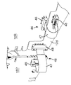
- FIG. 8 schematically shows an apparatus of this type.
- the operating device shown in the figure includes a circuit board 90 to which an electric circuit is wired, a plurality of dial devices 92A, 92B, and 92C mounted on the circuit board, and a board support 94 that supports the circuit board 90.
- Each of the dial devices 92A, 92B, and 92C includes a dial knob 95 that receives a rotation operation, and a dial element 96 that detects a rotational position of the dial knob 95 and outputs a signal corresponding to the detected position.
- the substrate support 94 includes a panel 98 positioned on the front side of the printed circuit board 90.
- the panel 98 has a plurality of through holes 98a, 98b, 98c through which the dial devices 92A, 92B, 92C can be inserted.
- the circuit board 90 is supported by the board support 94 such that the dial knobs 95 of the dial devices 92A to 92C protrude from the back side of the panel 98 to the front side through the through holes 98a to 98c.
- a plurality of dial devices 92A to 92C are mounted on a common circuit board 90, and the relative positions of these dial devices 92A to 92C are fixed.
- the relative positional relationship with the panel 98 cannot be individually set and adjusted.
- the relative positions of the dial devices 92A to 92C vary due to the warp of the circuit board 90, so that the relative positional relationship between the dial devices 92A to 92C and the corresponding through holes 98a, 98b, 98c of the panel 98. This may cause an adverse effect on the appearance and assembly of the device.
- An object of the present invention is to provide a vehicular dial operation device capable of individually setting the relative positional relationship between a panel and a plurality of dial devices without causing significant complication of the wiring structure.
- the vehicle dial operation device includes a dial knob that receives a rotation operation, three or more dial devices each having a dial element that outputs a signal corresponding to the rotation position of the dial knob, and each of the dial devices. And three or more circuit boards on which the corresponding dial devices are respectively mounted, and three or more through holes into which the dial knobs of the respective dial devices can be inserted, and through each through hole of the panel A board support that supports the circuit boards so that the circuit boards are arranged along a specific board arrangement direction in a state where the dial knobs protrude to the front side of the panel, and the circuit boards are electrically connected to each other. And a plurality of wiring members for connection.
- a main board having an external circuit connecting portion connected to a circuit outside the apparatus, a first sub-board adjacent to the main board, and the first sub-board are sandwiched between A second sub-board disposed on the opposite side of the main board, and as the wiring material, a first wiring material for connecting the main board and the first sub-board, the main board, and the And a second wiring member for connecting the second sub-board.
- the main board has a main body located on the opposite side of the second sub board across the first sub board, and the main board crosses the first sub board from the main body arrangement direction. Extending to the vicinity of the second sub-board through a region adjacent to the second sub-board, and the second wiring member extends over the extension and the second sub-board. Provided.
- a circuit board on which a plurality of dial devices are to be mounted is divided for each dial device, and the divided plurality of circuit boards are individually supported by a substrate support, so that the panel and the plurality of dials The relative positional relationship with the apparatus can be set individually. Furthermore, even if the main board, the first sub board, and the second sub board need to be arranged in a specific board arrangement direction in this order due to the layout of each dial device, the main board. In addition to the connection between the main board and the first sub board, the main board is connected to the main board by the presence of an extension extending from the main body part to the second sub board through a region adjacent to the first sub board. Connection between the substrate and the second sub-substrate is also performed with a simple wiring structure.
- FIG. 3 is a sectional view taken along line III-III in FIG. 2. It is the perspective view which looked at the plurality of circuit boards arranged in the dial operating device for vehicles from the front side. It is the perspective view which looked at the said circuit board from the back side. It is the rear view which looked at the said circuit board from the back side. It is a perspective view which shows the principal part of the said circuit board. It is sectional drawing which showed the conventional dial operating device typically.
- the dial operation device is for operating an air conditioner (air conditioner) mounted on a vehicle, but the operation target of the operation device according to the present invention is limited to the air conditioner. Absent.
- the present invention can also be applied to an apparatus for operating audio equipment and room lighting equipment.
- 1 to 5 includes a plurality (three in the figure) of dial devices 10D, 10R, and 10P and a flat circuit board 12D on which these dial devices 10D, 10R, and 10P are mounted. , 12R, 12P and a substrate support for supporting these circuit boards 12D, 12R, 12P. That is, in this dial operation device, the circuit board on which each dial device 10D, 10R, 10P is to be mounted is divided for each dial device, and these circuit boards are supported by a common substrate support.
- the substrate support includes a panel 14 facing the vehicle interior and a rear cover 16 disposed on the back side of the panel 14, and the rear cover 16 holds the circuit boards 12D, 12R, and 12P. Bonded to the panel 14.
- rubber sheets 15A and 15B are interposed between the panel 14 and the circuit boards 12D, 12R, and 12P.
- the dial devices 10D, 10R, and 10P having the same shape and structure are used.
- Each of the dial devices 10D, 10R, and 10P includes a cylindrical dial knob 18 that is rotated and a dial element 20 that rotatably supports the dial knob 18 around a rotation operation axis X that is a central axis thereof.
- the dial element 20 is mounted on the circuit board in such a posture that the rotation operation axis X matches the normal direction of the corresponding circuit board.
- the dial element 20 detects the rotational position of the dial knob 18 and outputs a signal corresponding to the position to a circuit in the circuit board on which the dial element 20 is mounted.
- the dial device 10D is rotated to adjust the state of air sent from the air conditioner toward the driver's seat.
- the dial devices 10R and 10P are operated to adjust the state of air sent toward the rear seat and the passenger seat, respectively.
- the dial devices 10D, 10R, and 10P according to this embodiment are rotated to adjust the air temperature as the “air state”.
- the “air state” may be, for example, an air volume.
- the circuit boards 12D, 12R, and 12P are arranged in parallel with each other so that the dial knobs 18 of the dial devices 10D, 10R, and 10P are arranged in the horizontal direction (that is, the respective circuit boards 12D, 12R, and 12P).
- the rotary operation axes X of the dial devices 10D, 10R, and 10P are supported by the substrate support). That is, the circuit boards 12D, 12R, and 12P are arranged along a horizontal direction corresponding to a specific board arrangement direction in this embodiment.
- the total number of dial devices and circuit boards and the specific board arrangement direction are not limited.
- a circuit board other than the main board and the first and second sub-boards may be included.
- the substrate arrangement direction may be the vertical direction.
- the rotation operation axes of a specific dial device may be inclined with respect to each other.
- the panel 14 constituting the substrate support has a plurality of through holes 14d, 14r, and 14p for the dial devices 10D, 10R, and 10P.
- These through holes 14d, 14r, and 14p each have a shape that allows the dial knob 18 of the corresponding dial device to be inserted from the back side toward the front side (in this embodiment, circular shapes having the same diameter).
- a plurality of mode switching buttons 22 that are pressed to switch the air-conditioning mode.
- a seesaw type air volume setting button 23 that is pressed to set the air volume in common
- a power button 24 for switching on and off the power and a plurality of indicators 26 for displaying the air volume are provided.
- an air volume setting button 27 operated to set the air volume of the air for the rear seat independently of the driver seat, and the air volume thereof
- an indicator 28 for displaying is provided.
- a plurality of push switch elements 32 that respectively receive a pressing operation by the mode switching button 22, the seesaw type air volume setting button 23, and the power button 24 and output signals respectively.
- a pair of pressure switch elements 33 and pressure switch elements 34 (FIG. 4) and a plurality of light emitting elements 36 for illuminating each indicator 26 are mounted, and the air volume setting button 27 is provided on the circuit board 12R.
- a pair of pressing switch elements 37 that receive a pressing operation and output a signal, and a plurality of light emitting elements 38 for illuminating each indicator 28 are mounted.
- the circuit board 12D corresponds to the main board, and on top of that, in addition to the dial device 10D for adjusting the temperature of the air supplied to the driver's seat, Elements constituting an operating device that contributes to the operation are mounted.
- circuit board 12D among the circuit boards 12D, 12R, and 12P is typically provided with a communication unit and a power input unit.
- the communication unit is configured to collectively communicate between the circuit boards 12D, 12R, and 12P and an external circuit (circuit mounted on the vehicle) outside the vehicle dial operation device,
- the power supply input unit is used to collectively connect the circuit boards 12D, 12R, and 12P and the power supply circuit.
- an external connection connector (external connection unit) 40 and a communication control circuit element 42 as shown in FIG. 5 are provided on the back surface of the circuit board 12D. Has been implemented.
- the external connection connector 40 is a connector that can be fitted to a mating connector provided on a vehicle wire harness (not shown), and is connected to a power supply line in the vehicle wire harness by the fitting. And a signal terminal connected to a communication signal line in the vehicle wire harness by the fitting. Then, the external connection connector 40 is connected to the circuit board 12D so that the power input terminal and the signal terminal are electrically connected to a power feeding circuit and a communication circuit included in the circuit board 12D, respectively. It is mounted on the back side. That is, the external connection connector 40 according to this embodiment serves as both a connector constituting the power input unit and a connector constituting the communication unit.
- the communication control circuit element 42 is formed of an IC chip or the like, and is provided in a communication circuit included in the circuit board 12D.
- the circuit board 12D, the circuit boards 12R and 12P, and the external connection connector 40 are provided. The communication control with the external circuit connected to the communication terminal is collectively performed.
- the circuit board 12D that is, the main board is connected to the circuit board 12R corresponding to the first sub-board and the circuit board 12D corresponding to the second sub-board, respectively, by the first first wiring member 44 and the second wiring member 46. Are connected to each other.
- the first wiring member 44 is provided on the circuit board 12D and a power supply line for electrically connecting a power supply circuit provided on the circuit board 12D and a power supply circuit provided on the circuit board 12R.
- a communication circuit including a communication unit and a signal line for electrically connecting the communication circuit included in the circuit board 12R are included.
- the second wiring member 46 is provided on the circuit board 12R and a power supply line for electrically connecting a power supply circuit provided on the circuit board 12R and a power supply circuit provided on the circuit board 12P.
- the power supplied to the power supply circuit of the circuit board 12D through the external connector 40 is also supplied to the power supply circuit of the circuit board 12R through the first wiring member 44, and in parallel therewith.
- the power is also supplied to the power supply circuit of the circuit board 12P through the second wiring member 46.
- the communication circuits of both circuit boards 12R and 12P corresponding to the sub-boards are connected to the communication circuit of the circuit board 12D which is the main board through the first wiring member 44 and the second wiring member 46, respectively. In this way, the communication circuit group that cooperates with each other communicates with an external circuit through the external connection connector 40 of the circuit board 12D.
- Each of the wiring members 44 and 46 includes, for example, a flat cable 47 and a pair of wiring connectors 48 as shown in the figure.
- the flat cable 47 includes a plurality of flexible conductors and a sheet-like insulating layer covering these conductors, and changes in relative positions of circuit boards adjacent to each other (particularly the thickness of the circuit boards). It is flexible enough to allow changes in relative position with respect to direction.
- Each of the wiring connectors 48 is mounted on a target circuit board and has a shape into which an end of the flat cable 47 can be inserted. And while holding the edge part of the inserted flat cable 47, the electrical connection of the conductor contained in this flat cable 47 and the circuit contained in the circuit board in which the said connector 48 for wiring was mounted is performed. .
- a circuit board 12D as a main board includes a main body 12b located on the opposite side of the circuit board 12P with the central circuit board 12R interposed therebetween, and the main body An extension 12d extending from 12b to a region below the central circuit board 12R, that is, in a direction orthogonal to the substrate arrangement direction, through a region adjacent to the circuit board 12R to the vicinity of the opposite circuit board 12P.
- the wiring members 44 and 46 are provided so as to straddle the extension 12d and the circuit boards 12R and 12P.
- the main body portion 12b of the circuit board 12D as the main board and the circuit board 12P as the second sub board are separated from each other with the circuit board 12R as the first sub board interposed therebetween.
- the circuit boards 12D and 12P can be directly connected to each other through the second wiring member 46 without extending the second wiring member 46.
- the connection of the wiring members 44 and 46 to the extension 12d means that the main body portion of the circuit board 12D is secured in order to secure a space for connection between the wiring members 44 and 46 and the circuit board 12D. There is no need to increase the area of 12b, thereby avoiding an increase in the size of the entire apparatus.
- the total occupied area of the circuit board 12D as the main board may be increased by the extension portion 12d, but the circuit board as the first sub board is reduced in size accordingly. Thus, it is possible to avoid an increase in the occupied area of the entire circuit board.
- the dial device corresponding to the main board at least two wiring members 44 and 46 need to be connected to the main board, and an external circuit connection portion (in this embodiment, the external connection connector 40).
- the circuit board 12R corresponding to the first sub board is not necessarily required, and the circuit structure is simpler than the circuit board 12D as the main board. Therefore, it is extremely reasonable to make the circuit board 12R smaller while extending the extension part 12d from the main body part 12b of the circuit board 12D in order to effectively use the board area.
- the maximum dimension of the circuit board 12R that is the first sub-board is larger than the maximum dimension of the main body 12b.
- the maximum value of the sum of the dimension of the first sub-board and the dimension of the extension is smaller than the maximum dimension of the main body.
- circuit boards 12R and 12P which are sub-boards according to this embodiment, and the extension part 12d are both end parts (that is, upper end part and lower end part) of the circuit board 12D, which is the main board, in the direction orthogonal to the board arrangement direction
- These shapes are set so that the circuit boards 12R, 12P and the extension part 12d are all contained in a region sandwiched by straight lines extending in the board arrangement direction (here, the horizontal direction) from the board part. Therefore, the circuit boards 12D, 12R, and 12P can be more compactly accommodated regardless of the addition of the extension 12d.
- the rear cover 16 has a plurality of boss portions 16d, 16r, and 16p for supporting the circuit boards 12D, 12R, and 12P from the back side.
- Each of the boss portions 16d, 16r, and 16p has a support surface that faces the front side (that is, the circuit board side and the panel side) and a screw hole that also opens to the front side.
- a through-hole 52 or a notch 54 is formed at a position corresponding to each screw hole, and the through-hole 52 or the notch 54 is inserted from the front side of the not illustrated.
- the circuit boards 12D, 12R, and 12P When the fixing screws are screwed into the screw holes, the circuit boards 12D, 12R, and 12P have the bosses in contact with the front surfaces (support surfaces) of the boss portions 16d, 16r, and 16P on the back surfaces. Fastened to the parts 16d, 16r, 16p. In this fastening, fine adjustment of the position where each of the circuit boards 12D, 12R, 12P is fixed to the rear cover 16 by the clearance between the fixing screw and the through hole 52 or the notch 54 (in other words, The fine adjustment of the relative positions of the circuit boards 12D, 12R, and 12P with respect to the panel 14 can be performed individually.
- the rear cover 16 holding the circuit boards 12D, 12R, and 12P is joined to the panel 14 with the rubber sheets 15A and 15B interposed therebetween, whereby the circuit boards 12D and 12R are joined.
- the dial knobs 18 of the respective dial devices 10D, 10R, 10P mounted on the circuit board respectively penetrate the through holes 14d, 14r, 14p of the panel 14 from the back side, respectively, and the front side of the panel 14 Is supported at a position protruding from the top.
- the dial knob 18 of each dial device 10D, 10R, 10P can be gripped and rotated by a driver or the like from the front side of the panel 14.
- the surface of the panel 14 of the dial operation device is appropriately undulated in a direction parallel to the rotation operation axis X of each of the dial devices 10D, 10R, 10P, and the through holes 14d, 14r , 14p are different from each other in the direction.
- the circuit boards 12D, 12R by the rear cover 16 are arranged so that the amount of protrusion of the dial knob 18 of each dial device 10D, 10R, 10P from the surface of the panel 14 is substantially equal.
- 12P is set. That is, among the circuit boards 12D, 12R, and 12P, the rear cover is arranged such that the circuit board 12D is located on the most front side (upper side in FIG. 3) and the circuit board 12P is located on the rearmost side (lower side in FIG. 3). 16, the holding positions of the circuit boards 12D, 12R, and 12P are set.
- the surface of the panel 14 may be a plane orthogonal to the rotation operation axes X.
- the specific structure of the substrate support is not limited.
- the circuit boards 12D, 12R, and 12P may be fixed to the panel 14 side. Even in this case, it is possible to individually set and adjust the relative positional relationship between the panel 14 and the circuit boards 12D, 12R, and 12P.
- the length of the extension 12d shown in FIG. 6 may be smaller than the dimension of the circuit board 12R as the first sub board in the board arrangement direction.
- the second wiring member extends from the circuit board 12P, which is the second sub-board, to the distal end side of the extension part 12d and extends over the extension part and the extension part 12d. Even if 46 is interposed, the wiring length can be kept short.
- the first wiring member 44 shown in the figure may be provided between the circuit board 12R and the main body 12b. However, in this case, a space for connection of the first wiring member 44 is required in the main body portion 12b. On the other hand, in the structure shown in FIGS. It is not necessary to secure a space for the connection of the first wiring member 44 on the main body 12b side.
- the third sub-board may be arranged on the side adjacent to the second sub-board, or arranged so as to be directly adjacent to the main board on the opposite side. May be.
- the extension portion may be extended from the main body portion of the main board to the vicinity of the third sub board.
- the present invention provides a vehicular dial operation device capable of individually setting the relative positional relationship between a panel and a plurality of dial devices without significantly complicating the wiring structure.
- This device includes a dial knob that receives a rotation operation, three or more dial devices each having a dial element that outputs a signal corresponding to the rotational position of the dial knob, and a dial device corresponding to each of the dial devices.
- Each having three or more circuit boards mounted thereon, and three or more through holes into which the dial knobs of the respective dial devices can be respectively inserted, and each of the dial knobs of the panel through each through hole of the panel.
- a circuit board a main board having an external circuit connection portion connected to a circuit outside the apparatus, a first sub board adjacent to the main board, and the main board across the first sub board A second sub-board disposed on the opposite side of the first sub-board, the first sub-board connecting the main board and the first sub-board as the wiring member, the main board and the second sub-board.
- a second wiring member for connecting to the sub-substrate.
- the main board has a main body located on the opposite side of the second sub board across the first sub board, and the main board crosses the first sub board from the main body arrangement direction. Extending to the vicinity of the second sub-board through a region adjacent to the second sub-board, and the second wiring member extends over the extension and the second sub-board. Provided.
- each circuit board on which a plurality of dial operation devices are mounted is divided for each dial operation device, the relative position between each dial operation device and the panel can be set individually.
- a circuit board having a connection portion with an external circuit is specified only as a specific main board, and the main board and other circuit boards (at least the first sub-board and the second board) are specified.
- each circuit board can be connected to an external circuit with a simple wiring structure.
- the main board is located on a side opposite to the second sub board across the first sub board, and the main body from the first sub board to the first sub board.
- An extension portion extending through a region adjacent to the direction perpendicular to the substrate arrangement direction to the vicinity of the second sub-substrate, and extending over the extension portion and the second sub-substrate. 2 is provided, the main wiring board main body and the second sub-board are separated from each other with the first sub-board being sandwiched between them.
- the main board and the second sub board can be directly connected via the second wiring member without extending.
- the second wiring member is connected to the extension portion of the main substrate, it is necessary to enlarge the area of the main body portion of the main substrate in order to secure a space for connection of the second wiring member.
- the overall size of the apparatus can be avoided.
- the first wiring member is provided so as to straddle the extension portion and the first sub-board, a space for connecting the first wiring member and the main board is secured. Therefore, it is not necessary to enlarge the area of the main body.
- the occupied area of the entire main board may be increased by the extension, but by reducing the size of the first sub board, the occupied area of the entire circuit board is increased. It is possible to avoid it.
- at least two wiring members (first wiring member and second wiring member) need to be connected to the main board, and an external circuit connection portion is always provided.
- the first sub-board is not necessarily required, and the circuit configuration is simpler than that of the main board. It is extremely reasonable to reduce the size of the first sub-board while extending the portion, in order to effectively use the board area.
- the maximum dimension of the first sub-board is smaller than the maximum dimension of the main body of the main board, and the dimension of the first sub-board and the extension
- the maximum value of the sum of the dimensions of the portion can be equal to or less than the maximum size of the main body portion, so that the first sub-board and the extension portion are not juxtaposed in the direction. An increase in the size of the apparatus can be avoided.
- the shapes of the extensions of the first sub-board, the second sub-board, and the main board are respectively determined from both ends of the main board body in the direction orthogonal to the board arrangement direction. As long as the shape fits within a region sandwiched by straight lines extending along the board arrangement direction, a plurality of circuit boards including the main board can be more compactly accommodated regardless of the addition of the extension to the main board. Is possible.
- the external circuit connection portion can be provided only on the main board among the main board, the first sub-board, and the second sub-board. And wiring with an external circuit can be eliminated.
- a control circuit may be provided.
- the first wiring material and the second wiring material are provided on the communication control circuit, the first sub-board, and the second sub-board.
- a signal line for transmitting a signal related to the communication with the communication circuit may be included.
- the communication unit is typically provided only on the main board to simplify the structure and wiring, while the main apparatus is similar to the conventional apparatus in which a plurality of dial devices are mounted on a single circuit board. Communication between the substrate and both sub-substrates and the external circuit can be performed collectively.
- the external circuit connection unit may include a power input unit for collectively connecting the main substrate, the first sub-substrate, the second sub-substrate, and the power circuit thereof.
- the first wiring member and the second wiring member may include a power supply line for supplying the sub-board with power input from the power input unit.
- the power supply is input only to the main board, thereby simplifying the structure and wiring, and all the power supply from the power input section to the main board and further to the sub board can be performed. .
- the dial operation device is useful, for example, as an operation device for air conditioning equipment mounted on a vehicle.
- the main board includes a dial device operated to adjust the state (temperature, air volume, etc.) of air sent from an air conditioner mounted on the vehicle to the driver's seat, and operations other than the dial device.
- an element that constitutes an operating device that contributes to another operation of the air conditioner, and the first sub-board has a state of air sent from the air conditioner to the rear seat.
- a dial device operated to adjust is mounted, and the second sub-board is mounted with a dial device operated to adjust the state of air sent from the air conditioner to the passenger seat,
- the main board and the two sub boards are arranged in a substantially horizontal direction, the main board is disposed on the side close to the driver seat, and the second sub board is on the side close to the passenger seat. Which is disposed, it is preferable.
- a dial device for a driver's seat that is frequently operated by a driver and other elements constituting the operating device are mounted on a main board, and an external circuit connecting portion is provided only on the main board. And the main board is arranged on the driver's seat side, thereby facilitating the operation by the driver and constructing a rational communication system between the circuit boards centering on the main board.
- the second sub-board for the passenger seat on the opposite side of the main board across the first sub-board for the rear seat, the passenger in the passenger seat can place the second sub-board. It becomes easy to operate the upper dial device.
- the main board (with the simple structure as described above is provided by the extension of the main board. Electrical connection between the driver's seat board) and the second sub board (passenger seat board) is achieved.
Landscapes
- Engineering & Computer Science (AREA)
- Chemical & Material Sciences (AREA)
- Combustion & Propulsion (AREA)
- Transportation (AREA)
- Mechanical Engineering (AREA)
- Microelectronics & Electronic Packaging (AREA)
- Rotary Switch, Piano Key Switch, And Lever Switch (AREA)
- Combinations Of Printed Boards (AREA)
Abstract
この発明は、簡素な配線構造で、パネルに対する複数のダイヤル装置の相対位置関係を個別に設定することが可能な車両用ダイヤル操作装置を提供する。このダイヤル操作装置は、複数のダイヤル装置と、特定方向に並び、各ダイヤル装置が個別に実装される複数の回路基板12D,12R,12Pと、パネルを含んで各回路基板を支持する基板支持体とを備える。回路基板12Dは、外部回路との接続部をもつメイン基板であり、配線材44,46をそれぞれ介してサブ基板である各回路基板12R,12Pと接続される。回路基板12Dは、回路基板12Rに隣接する本体部12bと、この本体部12bから回路基板12Rに隣接する領域を通って回路基板12Pへ延びる延長部12dとを有し、この延長部12dと回路基板12Pとの間に配線材46が設けられる。
Description
本発明は、自動車等の車両に設けられ、それぞれ回転操作を受ける複数のダイヤル装置を具備する車両用ダイヤル操作装置に関するものである。
従来、車両に設けられるダイヤル操作装置として、例えば特許文献1に記載されるように、複数のダイヤル装置が共通の回路基板(同文献ではプリント基板)上に実装されたものが知られている。
図8は、かかるタイプの装置を模式的に示したものである。同図に示される操作装置は、電気回路が配線される回路基板90と、この回路基板上に実装される複数のダイヤル装置92A,92B,92Cと、前記回路基板90を支持する基板支持体94とを備える。前記各ダイヤル装置92A,92B,92Cは、回転操作を受けるダイヤルノブ95と、このダイヤルノブ95の回転位置を検出してその検出位置に応じた信号を出力するダイヤル素子96とを有する。前記基板支持体94は、前記プリント基板90の前側に位置するパネル98を含み、このパネル98には、前記各ダイヤル装置92A,92B,92Cが挿通可能な複数の貫通孔98a,98b,98cが設けられ、これらの貫通孔98a~98cを通じて前記各ダイヤル装置92A~92Cのダイヤルノブ95がそれぞれ前記パネル98の裏側から表側に突出するように、前記回路基板90が前記基板支持体94に支持される。
この操作装置では、共通の回路基板90上に複数のダイヤル装置92A~92Cが実装されていて、これらダイヤル装置92A~92C同士の相対位置は固定されているため、当該各ダイヤル装置92A~92Cとパネル98との相対位置関係を個別に設定および調整することができない。また、前記回路基板90の反りによってダイヤル装置92A~92C同士の相対位置が変動することにより、当該ダイヤル装置92A~92Cとこれらに対応するパネル98の貫通孔98a,98b,98cとの相対位置関係が狂い、これが装置の外観や組立に悪影響を与えるおそれがある。
本発明者らは、パネルと複数のダイヤル装置との相対位置関係を個別に設定することを可能にするため、回路基板をダイヤル装置ごとに分割することに想到した。しかし、この回路基板の分割は配線構造の複雑化を招くため、その抑制が重要な課題となる。本発明の目的は、配線構造の著しい複雑化を招くことなく、パネルと複数のダイヤル装置との相対位置関係を個別に設定することが可能な車両用ダイヤル操作装置を提供することにある。
本発明が提供する車両用ダイヤル操作装置は、回転操作を受けるダイヤルノブ及び当該ダイヤルノブの回転位置に対応する信号を出力するダイヤル素子をそれぞれ有する3つ以上のダイヤル装置と、前記各ダイヤル装置ごとに分割され、対応するダイヤル装置がそれぞれ実装される3枚以上の回路基板と、前記各ダイヤル装置のダイヤルノブがそれぞれ挿通可能な3つ以上の貫通孔を有し、当該パネルの各貫通孔を通じて前記各ダイヤルノブが前記パネルの表側に突出する状態で前記各回路基板をこれらの回路基板が特定の基板配列方向に沿って並ぶように支持する基板支持体と、前記回路基板同士を電気的に接続するための複数の配線材とを備える。この装置は、前記回路基板として、装置外部の回路と接続される外部回路接続部を有するメイン基板と、このメイン基板に隣接する第1のサブ基板と、この第1のサブ基板を挟んで前記メイン基板と反対の側に配置される第2のサブ基板とを含み、前記配線材として、前記メイン基板と前記第1のサブ基板とを接続する第1の配線材と、前記メイン基板と前記第2のサブ基板とを接続する第2の配線材とを含む。前記メイン基板は、前記第1のサブ基板を挟んで前記第2のサブ基板と反対の側に位置する本体部と、この本体部から前記第1のサブ基板に対して前記基板配列方向と直交する方向に隣接する領域を通って前記第2のサブ基板の近傍に至るまで延びる延長部とを有し、この延長部と前記第2のサブ基板とに跨るように前記第2の配線材が設けられる。
この装置では、複数のダイヤル装置が実装されるべき回路基板が当該ダイヤル装置毎に分割され、その分割された複数の回路基板が個別に基板支持体に支持されることが、パネルと複数のダイヤル装置との相対位置関係を個別に設定することを可能にする。さらに、各ダイヤル装置のレイアウトの都合上、前記メイン基板、前記第1のサブ基板、および前記第2のサブ基板をこれらの順に特定の基板配列方向に配列しなければならない場合でも、前記メイン基板の本体部から前記第1のサブ基板に隣接する領域を通って前記第2のサブ基板へ延びる延長部の存在により、当該メイン基板と当該第1のサブ基板との接続のみならず、当該メイン基板と当該第2のサブ基板との接続も簡素な配線構造で行われる。
本発明の好ましい実施の形態を図1~図7を参照しながら説明する。なお、この実施の形態に係るダイヤル操作装置は、車両に搭載される空調機器(エアコンディショナー)の操作を行うためのものであるが、本発明に係る操作装置の操作対象は空調機器に限られない。例えば、オーディオ機器や室内照明機器の操作のための装置にも本発明が適用されることが可能である。
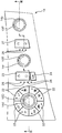
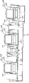
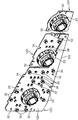
図1~図5に示されるダイヤル操作装置は、複数(図では3個)のダイヤル装置10D,10R,10Pと、これらのダイヤル装置10D,10R,10Pがそれぞれ実装される平板状の回路基板12D,12R,12Pと、これらの回路基板12D,12R,12Pを支持する基板支持体とを備える。すなわち、このダイヤル操作装置では、各ダイヤル装置10D,10R,10Pが実装されるべき回路基板が当該ダイヤル装置ごとに分割され、かつ、これらの回路基板が共通の基板支持体に支持される。この基板支持体は、車室内に面するパネル14と、このパネル14の裏側に配置されるリアカバー16とを有し、このリアカバー16が前記各回路基板12D,12R,12Pを保持した状態で前記パネル14に接合される。また、この実施の形態では、前記パネル14と前記各回路基板12D,12R,12Pとの間にラバーシート15A,15Bが介設される。
この実施の形態では、前記ダイヤル装置10D,10R,10Pに互いに同一の形状及び構造を有するものが用いられる。各ダイヤル装置10D,10R,10Pは、回転操作される円筒状のダイヤルノブ18と、このダイヤルノブ18をその中心軸である回転操作軸X回りに回転可能に支持するダイヤル素子20とを備え、前記回転操作軸Xが、対応する回路基板の法線方向と合致する姿勢で、当該回路基板上に前記ダイヤル素子20が実装される。このダイヤル素子20は、前記ダイヤルノブ18の回転位置を検出してその位置に対応する信号を当該ダイヤル素子20が実装された回路基板内の回路に出力する。
前記各ダイヤル装置10D,10R,10Pのうち、前記ダイヤル装置10Dは、前記空調機器から運転席に向かって送られる空気の状態を調節するために回転操作されるものである。一方、前記ダイヤル装置10R,10Pは、それぞれ、後部座席及び助手席に向かって送られる空気の状態を調節するために操作されるものである。この実施の形態に係るダイヤル装置10D,10R,10Pは、前記の「空気の状態」として空気温度を調節するために回転操作される。しかし、当該「空気の状態」は例えば風量であってもよい。
前記各回路基板12D,12R,12Pは、この実施の形態では、前記各ダイヤル装置10D,10R,10Pのダイヤルノブ18が水平方向に沿って並ぶように、互いに平行となる姿勢で(すなわち前記各ダイヤル装置10D,10R,10Pの回転操作軸Xが互いに平行となる姿勢で)前記基板支持体に支持される。すなわち、当該回路基板12D,12R,12Pは、この実施の形態において特定の基板配列方向に相当する水平方向に沿って配列される。ただし、本発明ではダイヤル装置及び回路基板の総数や具体的な基板配列方向は限定されない。例えばメイン基板並びに第1および第2のサブ基板以外の回路基板が含まれていてもよい。また、基板配列方向は上下方向であってもよい。あるいは、特定のダイヤル装置の回転操作軸同士が互いに傾斜していてもよい。
この基板支持体を構成するパネル14は、前記各ダイヤル装置10D,10R,10Pのための複数の貫通孔14d,14r,14pを有する。これらの貫通孔14d,14r,14pは、それぞれ、対応するダイヤル装置のダイヤルノブ18が裏側から表側に向かって挿通可能な形状(この実施の形態では互いに等しい直径をもつ円形)をなす。
さらに、運転席用ダイヤル装置10Dに対応する貫通孔14dの周囲には、空調モードを切換えるために押圧操作される複数のモード切換ボタン22が配列されるとともに、その傍らに、運転席及び助手席に共通して風量を設定するために押圧操作されるシーソー式の風量設定ボタン23と、電源のオンオフを切換えるための電源ボタン24と、風量を表示するための複数のインジケータ26とが配設される。また、後部座席用ダイヤル装置10Rに対応する貫通孔14rの近傍には、前記運転席とは独立して後部座席用の空気の風量を設定するために操作される風量設定ボタン27と、その風量を表示するためのインジケータ28とが配設される。これらに対応して、前記回路基板12D上には、前記モード切換ボタン22、シーソー式の前記風量設定ボタン23及び電源ボタン24によりそれぞれ押圧操作を受けて信号をそれぞれ出力する複数の押圧スイッチ素子32、一対の押圧スイッチ素子33及び押圧スイッチ素子34(図4)と、前記各インジケータ26を照明するための複数の発光素子36とが実装され、前記回路基板12R上には、前記風量設定ボタン27により押圧操作を受けて信号を出力する一対の押圧スイッチ素子37と、前記各インジケータ28を照明するための複数の発光素子38とが実装されている。
すなわち、この実施の形態では回路基板12Dがメイン基板に相当し、その上には、運転席に供給される空気の温度を調節するためのダイヤル装置10Dに加え、それ以外の空調機器の他の操作に寄与する操作装置を構成する素子が実装されている。
さらに、前記回路基板12D,12R,12Pのうちの回路基板12Dにのみ、代表的に、通信部及び電源入力部が設けられる。前記通信部は、各回路基板12D,12R,12Pと車両用ダイヤル操作装置の外部の外部回路(車両に搭載された回路)との間で一括して通信を行わせるためのものであり、前記電源入力部は、前記回路基板12D,12R,12Pとその電源回路との接続を一括して行うためのものである。
具体的に、この実施の形態では、前記通信部及び電源入力部として、当該回路基板12Dの裏面上に図5に示すような外部接続用コネクタ(外部接続部)40及び通信制御用回路素子42が実装されている。
前記外部接続用コネクタ40は、図略の車両用ワイヤハーネスに設けられた相手方コネクタと嵌合可能なコネクタであって、当該嵌合によって当該車両用ワイヤハーネス内の給電線に接続される電源入力用端子と、当該嵌合によって当該車両用ワイヤハーネス内の通信用の信号線に接続される信号用端子とを含む。そして、前記電源入力用端子及び前記信号用端子が前記回路基板12Dに含まれる給電用回路及び通信用回路にそれぞれ電気的に接続されるようにして、当該外部接続用コネクタ40が当該回路基板12Dの裏面上に実装されている。すなわち、この実施の形態に係る外部接続用コネクタ40は、前記電源入力部を構成するコネクタと前記通信部を構成するコネクタとを兼ねている。
前記通信制御用回路素子42は、ICチップ等からなり、前記回路基板12Dに含まれる通信用回路中に設けられ、この回路基板12Dさらには前記回路基板12R,12Pと、前記外部接続用コネクタ40の通信用端子に接続される外部回路との間での通信制御を一括して行う。
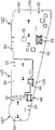
この回路基板12Dすなわちメイン基板は、第1のサブ基板に相当する回路基板12Rおよび第2のサブ基板に相当する回路基板12Dにそれぞれ第1の第1の配線材44および第2の配線材46をそれぞれ介して接続される。前記第1の配線材44は、前記回路基板12Dに設けられる給電回路と前記回路基板12Rに設けられる給電回路とを電気的に接続するための給電線と、前記回路基板12Dに設けられて前記通信部を含む通信用回路と前記回路基板12Rに含まれる通信用回路とを電気的に接続するための信号線とを含む。一方、前記第2の配線材46は、前記回路基板12Rに設けられる給電回路と前記回路基板12Pに設けられる給電回路とを電気的に接続するための給電線と、前記回路基板12Rに設けられる通信用回路と前記回路基板12Pに設けられる通信用回路とを電気的に接続するための信号線とを含む。
従って、前記外部接続用コネクタ40を通じて前記回路基板12Dの給電用回路に供給された電源は、前記第1の配線材44を通じて前記回路基板12Rの給電用回路にも供給され、これと並行して前記第2の配線材46を通じて前記回路基板12Pの給電用回路にも供給される。また、サブ基板に相当する両回路基板12R,12Pの通信用回路は前記第1の配線材44および前記第2の配線材46をそれぞれ介してメイン基板である回路基板12Dの通信用回路に接続され、このように相互連携した通信用回路群が前記回路基板12Dの外部接続用コネクタ40を通じて外部回路と通信を行う。
前記各配線材44,46は、例えば、図に示されるようなフラットケーブル47と一対の配線用コネクタ48とにより構成される。前記フラットケーブル47は、可撓性を有する複数本の導体と、これらの導体を覆うシート状の絶縁層とからなり、互いに隣接する回路基板同士の相対位置の変更(特に当該回路基板の板厚方向についての相対位置の変更)を許容するのに十分な可撓性を有する。前記各配線用コネクタ48は、対象となる回路基板上にそれぞれ実装されるとともに、前記フラットケーブル47の端部が挿入可能な形状を有する。そして、その挿入されたフラットケーブル47の端部を保持するとともに、このフラットケーブル47に含まれる導体と、当該配線用コネクタ48が実装された回路基板に含まれる回路との電気的な接続を行う。
この実施の形態では、前記配線構造を簡素にするため、メイン基板である回路基板12Dは、中央の回路基板12Rを挟んで回路基板12Pと反対の側に位置する本体部12bと、この本体部12bから中央の回路基板12Rの下方の領域、すなわち前記基板配列方向と直交する方向で前記回路基板12Rに隣接する領域を通って反対側の回路基板12Pの近傍に至るまで延びる延長部12dとを有し、この延長部12dと前記各回路基板12R,12Pとをそれぞれ跨ぐように前記各配線材44,46が設けられる。この構造では、メイン基板である回路基板12Dの本体部12bと第2のサブ基板である回路基板12Pとがその間に第1のサブ基板である回路基板12Rを挟んで隔たっているにもかかわらず、前記第2の配線材46を延長することなく当該第2の配線材46を介して回路基板12D,12P同士を直接接続することが可能である。さらに、前記各配線材44,46が延長部12dに接続されることは、これらの配線材44,46と回路基板12Dとの接続のためのスペースを確保するのに当該回路基板12Dの本体部12bの面積を拡大する必要をなくし、これにより、装置全体の大型化を回避することができる。
なお、前記メイン基板である回路基板12Dの全体の占有面積は、前記延長部12dの分だけ拡大される可能性があるが、その分、第1のサブ基板である回路基板を小型化することで、回路基板全体の占有面積の増大を回避することが可能である。前記メイン基板には、これに対応するダイヤル装置の他、少なくとも2つの配線材44,46が接続される必要があるのに加え、外部回路接続部(この実施の形態では外部接続用コネクタ40)が必ず設けられる必要があり、回路構成が複雑となるのに対し、第1のサブ基板に相当する回路基板12Rは必ずしもそれを要せず、メイン基板である回路基板12Dよりも回路構成が簡単であるので、この回路基板12Dの本体部12bから延長部12dを延長させる一方で前記回路基板12Rを小型化することは、基板面積の有効活用を図る上できわめて合理的である。
具体的に、この実施の形態では、前記基板配列方向と直交する方向(上下方向)の寸法について、前記第1のサブ基板である回路基板12Rの最大寸法が前記本体部12bの最大寸法よりも小さく、かつ、前記第1のサブ基板の寸法と前記延長部の寸法との和の最大値が前記本体部の最大寸法以下となっている。このため、当該上下方向に回路基板12Rと延長部12dとを並置しなからも当該方向についての装置の寸法の増大を回避することができる。
さらに、この実施の形態に係るサブ基板である回路基板12R,12Pおよび前記延長部12dについては、メイン基板である回路基板12Dの前記基板配列方向と直交する方向の両端部(すなわち上端部および下端部)からそれぞれ当該基板配列方向(ここでは水平方向)に沿って延長される直線によって挟まれる領域内に当該回路基板12R,12Pおよび延長部12dが全て収まるように、これらの形状が設定されているため、前記延長部12dの付加にかかわらず回路基板12D,12R,12Pをさらにコンパクトに収めることが可能となっている。
前記リアカバー16は、前記各回路基板12D,12R,12Pをそれぞれ裏側から支持するための複数のボス部16d,16r,16pを有する。各ボス部16d,16r,16pは、前側(すなわち回路基板側及びパネル側)に向かう支持面と、同じく前側に開口するねじ孔とを有する。一方、各回路基板12D,12R,12Pにおいて前記各ねじ孔に対応する位置には貫通孔52または切欠54が形成され、当該貫通孔52または当該切欠54に対して前側から挿通された図略の固定用ねじが前記各ねじ孔にねじ込まれることにより、各回路基板12D,12R,12Pは、その裏面に前記各ボス部16d,16r,16Pの前面(支持面)が当接した状態で当該ボス部16d,16r,16pに締結される。この締結にあたって、前記固定用ねじと前記貫通孔52または切欠54とのクリアランスの分だけ、リアカバー16に対して前記各回路基板12D,12R,12Pが固定される位置の微調整(換言すれば、パネル14に対する各回路基板12D,12R,12Pの相対位置の微調整)を個別に行うことが可能である。
このようにして、前記各回路基板12D,12R,12Pを保持した状態のリアカバー16が、ラバーシート15A,15Bを間に挟んで前記パネル14に接合されることにより、前記各回路基板12D,12R,12Pは、当該回路基板上にそれぞれ実装されている各ダイヤル装置10D,10R,10Pのダイヤルノブ18が当該パネル14の貫通孔14d,14r,14pをそれぞれ裏側から貫通して当該パネル14の表側に突出する位置に支持される。各ダイヤル装置10D,10R,10Pのダイヤルノブ18は、当該パネル14の表側から運転者等により把持されて回転操作されることが可能である。
なお、この実施の形態に係るダイヤル操作装置のパネル14の表面は、前記各ダイヤル装置10D,10R,10Pの回転操作軸Xと平行な方向に適宜起伏していて、前記各貫通孔14d,14r,14pの位置は当該方向について互いに異なっている。そして、この位置の相違にかかわらず、各ダイヤル装置10D,10R,10Pのダイヤルノブ18が前記パネル14の表面から突出する突出量が略同等になるように、リアカバー16による各回路基板12D,12R,12Pの保持位置が設定されている。つまり、前記回路基板12D,12R,12Pのうち回路基板12Dが最も前側(図3では上側)に位置し、回路基板12Pが最も後ろ側(図3では下側)に位置するように、前記リアカバー16による各回路基板12D,12R,12Pの保持位置が設定されている。
しかし、このような各ダイヤル装置10D,10R,10Pのダイヤルノブ18の突出量の調整は、本発明において必ずしも要しない。例えば、パネル14の表面は前記各回転操作軸Xと直交する平面であってもよい。
本発明では基板支持体の具体的な構造も限定されない。例えば、図1~図5に示されるダイヤル操作装置において、各回路基板12D,12R,12Pはパネル14側に固定されてもよい。その場合も、当該パネル14と各回路基板12D,12R,12Pとの相対位置関係を個別に設定および調整することが可能である。
また、本発明における回路基板の形状および配線形態についても、例えば次のような変更を行うことが可能である。
・図6に示される延長部12dの長さは、第1のサブ基板である回路基板12Rの基板配列方向の寸法より小さくてもよい。この場合において、例えば、第2のサブ基板である回路基板12Pから逆に前記延長部12dの先端側に延長部が延びて当該延長部と前記延長部12dとに跨るように第2の配線材46が介設されても、その配線長が短く抑えられる。
・同図に示される第1の配線材44は回路基板12Rと本体部12bとの間に設けられてもよい。ただし、この場合には当該本体部12bに第1の配線材44の接続のためのスペースが必要になるのに対し、図5~図7に示される構造では、延長部12dの有効利用により、第1の配線材44についてもその接続のためのスペースを本体部12b側に確保する必要がなくなる。
・サブ基板が3枚以上存在する場合、その第3のサブ基板は、第2のサブ基板に隣接する側に配置されてもよいし、これと反対側でメイン基板に直接隣接するように配置されてもよい。前者の場合、メイン基板の本体部から前記第3のサブ基板の近傍に至るまで前記延長部が延長されてもよい。
以上のように、本発明は、配線構造の著しい複雑化を招くことなく、パネルと複数のダイヤル装置との相対位置関係を個別に設定することが可能な車両用ダイヤル操作装置を提供する。この装置は、回転操作を受けるダイヤルノブ及び当該ダイヤルノブの回転位置に対応する信号を出力するダイヤル素子をそれぞれ有する3つ以上のダイヤル装置と、前記各ダイヤル装置ごとに分割され、対応するダイヤル装置がそれぞれ実装される3枚以上の回路基板と、前記各ダイヤル装置のダイヤルノブがそれぞれ挿通可能な3つ以上の貫通孔を有し、当該パネルの各貫通孔を通じて前記各ダイヤルノブが前記パネルの表側に突出する状態で前記各回路基板をこれらの回路基板が特定の基板配列方向に沿って並ぶように支持する基板支持体と、前記回路基板同士を電気的に接続するための複数の配線材とを備える。そして、前記回路基板として、装置外部の回路と接続される外部回路接続部を有するメイン基板と、このメイン基板に隣接する第1のサブ基板と、この第1のサブ基板を挟んで前記メイン基板と反対の側に配置される第2のサブ基板とを含み、前記配線材として、前記メイン基板と前記第1のサブ基板とを接続する第1の配線材と、前記メイン基板と前記第2のサブ基板とを接続する第2の配線材とを含む。前記メイン基板は、前記第1のサブ基板を挟んで前記第2のサブ基板と反対の側に位置する本体部と、この本体部から前記第1のサブ基板に対して前記基板配列方向と直交する方向に隣接する領域を通って前記第2のサブ基板の近傍に至るまで延びる延長部とを有し、この延長部と前記第2のサブ基板とに跨るように前記第2の配線材が設けられる。
この装置では、複数のダイヤル操作装置が実装される回路基板が、そのダイヤル操作装置毎に分割されているため、各ダイヤル操作装置とパネルとの相対位置を個別に設定することが可能である。しかも、その分割された回路基板のうち、外部回路との接続部を有する回路基板を特定のメイン基板のみに特定し、このメイン基板とそれ以外の回路基板(少なくとも第1のサブ基板および第2のサブ基板)とを配線材を介して接続することにより、簡素な配線構造で各回路基板と外部回路との接続を行うことが可能である。
さらに、前記装置では、各ダイヤル装置のレイアウトの都合上、前記メイン基板、前記第1のサブ基板、および前記第2のサブ基板をこれらの順に特定の基板配列方向に配列しなければならない場合でも、回路基板同士の接続を簡素な配線構造で行うことが可能である。具体的には、前記メイン基板が、前記第1のサブ基板を挟んで前記第2のサブ基板と反対の側に位置する本体部と、この本体部から前記第1のサブ基板に対して前記基板配列方向と直交する方向に隣接する領域を通って前記第2のサブ基板の近傍に至るまで延びる延長部とを有し、この延長部と前記第2のサブ基板とに跨るように前記第2の配線材が設けられるため、前記メイン基板の本体部と前記第2のサブ基板とがその間に前記第1のサブ基板を挟んで隔たっているにもかかわらず、前記第2の配線材を延長することなく当該第2の配線材を介して当該メイン基板と当該第2のサブ基板とを直接接続することが可能である。
また、前記第2の配線材は前記メイン基板の延長部に接続されるから、当該第2の配線材の接続のためのスペースを確保するのに当該メイン基板の本体部の面積を拡大する必要がなく、これにより、装置全体の大型化を回避することができる。さらに、当該延長部と前記第1のサブ基板とに跨るように前記第1の配線材が設けられるようにすれば、この第1の配線材とメイン基板との接続のためのスペースを確保するために前記本体部の面積を拡大することも不要になる。
なお、前記メイン基板全体の占有面積は、前記延長部の分だけ拡大される可能性があるが、その分、第1のサブ基板を小型化することで、回路基板全体の占有面積の増大を回避することが可能である。前記メイン基板には、これに対応するダイヤル装置の他、少なくとも2つの配線材(第1の配線材および第2の配線材)が接続される必要があるのに加え、外部回路接続部が必ず設けられる必要があり、回路構成が複雑となるのに対し、前記第1のサブ基板は必ずしもそれを要せず、メイン基板よりも回路構成が簡単であるので、前記メイン基板の本体部から延長部を延長させる一方で前記第1のサブ基板を小型化することは、基板面積の有効活用を図る上できわめて合理的である。
例えば、前記基板配列方向と直交する方向の寸法について、前記第1のサブ基板の最大寸法が前記メイン基板の本体部の最大寸法よりも小さく、かつ、前記第1のサブ基板の寸法と前記延長部の寸法との和の最大値が前記本体部の最大寸法以下とすることが可能であり、これにより、当該方向に第1のサブ基板と当該延長部とを並置しなからも当該方向についての装置の寸法の増大を回避することができる。
さらには、前記第1のサブ基板、前記第2のサブ基板、および前記メイン基板の延長部の形状が、これらが当該メイン基板の本体部の前記基板配列方向と直交する方向の両端部からそれぞれ当該基板配列方向に沿って延長される直線によって挟まれる領域内に収まる形状であれば、メイン基板への延長部の付加にかかわらず当該メイン基板を含む複数枚の回路基板をさらにコンパクトに収めることが可能である。
本発明では、前記外部回路接続部を、前記メイン基板、前記第1のサブ基板、および前記第2のサブ基板のうち、前記メイン基板にのみ設けることも可能であり、これにより、両サブ基板と外部回路との配線をなくすことができる。
例えば、前記メイン基板にのみ、このメイン基板及び前記第1のサブ基板および前記第2のサブ基板と前記車両用ダイヤル操作装置の外部の外部回路との間での通信制御を一括して行う通信制御回路が設けられてもよく、その場合には、前記第1の配線材および前記第2の配線材が、前記通信制御回路と前記第1のサブ基板および前記第2のサブ基板に設けられた通信用回路との間で前記通信に係る信号を伝送するための信号線を含めばよい。この装置では、前記メイン基板にのみ代表的に前記通信部を設けて構造及び配線の簡略化を図りながら、単一の回路基板上に複数のダイヤル装置が実装される従来装置と同様に、メイン基板および両サブ基板と前記外部回路との通信を一括して行うことができる。
さらに、前記外部回路接続部は、前記メイン基板、前記第1のサブ基板および前記第2のサブ基板とその電源回路との接続を一括して行うための電源入力部を含んでもよく、その場合、前記第1の配線材および前記第2の配線材が前記電源入力部から入力される電源を前記サブ基板に供給するための給電線を含めばよい。この装置では、前記メイン基板に対してのみ電源入力を行うことで構造及び配線の簡略化を図りながら、この電源入力部から前記メイン基板さらには前記サブ基板への電源供給を全て行うことができる。
本発明に係るダイヤル操作装置は、例えば車両に搭載される空調機器の操作装置として有用である。例えば、前記メイン基板には、車両に搭載される空調機器から運転席に対して送られる空気の状態(温度、風量など)を調節するために操作されるダイヤル装置と、当該ダイヤル装置以外の操作装置であって前記空調機器についての他の操作に寄与する操作装置を構成する素子とが実装され、前記第1のサブ基板には、前記空調機器から後部座席に対して送られる空気の状態を調節するために操作されるダイヤル装置が実装され、前記第2のサブ基板には、前記空調機器から助手席に対して送られる空気の状態を調節するために操作されるダイヤル装置が実装され、前記メイン基板および前記両サブ基板が略水平方向に沿って配列されるとともに、前記メイン基板が前記運転席に近い側に配置され、前記第2のサブ基板が前記助手席に近い側に配置されるものが、好適である。
このダイヤル操作装置では、運転者により操作される頻度の高い運転席用のダイヤル装置と、その他の操作装置を構成する素子とがメイン基板に実装され、かつ、このメイン基板にのみ外部回路接続部が設けられて当該メイン基板が運転席側に配置されることにより、運転者による操作を容易にするとともに、前記メイン基板を中心とした回路基板同士の合理的な通信系統を構築できる。その一方、後部座席用の第1のサブ基板を挟んで前記メイン基板と反対の側に助手席用の第2のサブ基板を配置することで、助手席の搭乗者が当該第2のサブ基板上のダイヤル装置を操作することが容易になる。しかも、この第2のサブ基板と前記メイン基板との間に前記第1のサブ基板が介在するにもかかわらず、当該メイン基板の延長部によって、上述のように簡素な構造で当該メイン基板(運転席用基板)と前記第2のサブ基板(助手席用基板)との電気的接続が達成される。
Claims (8)
- 車両に設けられるダイヤル操作装置であって、
回転操作を受けるダイヤルノブ及び当該ダイヤルノブの回転位置に対応する信号を出力するダイヤル素子をそれぞれ有する3つ以上のダイヤル装置と、
前記各ダイヤル装置ごとに分割され、対応するダイヤル装置がそれぞれ実装される3枚以上の回路基板と、
前記各ダイヤル装置のダイヤルノブがそれぞれ挿通可能な3つ以上の貫通孔を有し、当該パネルの各貫通孔を通じて前記各ダイヤルノブが前記パネルの表側に突出する状態で前記各回路基板をこれらの回路基板が特定の基板配列方向に沿って並ぶように支持する基板支持体と、
前記回路基板同士を電気的に接続するための複数の配線材とを備え、
前記回路基板として、装置外部の回路と接続される外部回路接続部を有するメイン基板と、このメイン基板に隣接する第1のサブ基板と、この第1のサブ基板を挟んで前記メイン基板と反対の側に配置される第2のサブ基板とを含み、
前記配線材として、前記メイン基板と前記第1のサブ基板とを接続する第1の配線材と、前記メイン基板と前記第2のサブ基板とを接続する第2の配線材とを含み、
前記メイン基板は、前記第1のサブ基板を挟んで前記第2のサブ基板と反対の側に位置する本体部と、この本体部から前記第1のサブ基板に対して前記基板配列方向と直交する方向に隣接する領域を通って前記第2のサブ基板の近傍に至るまで延びる延長部とを有し、この延長部と前記第2のサブ基板とに跨るように前記第2の配線材が設けられている、車両用ダイヤル操作装置。 - 請求項1記載の車両用ダイヤル操作装置において、
前記延長部と前記第1のサブ基板とに跨るように前記第1の配線材が設けられている、車両用ダイヤル操作装置。 - 請求項1または2記載の車両用ダイヤル操作装置において、
前記基板配列方向と直交する方向について、前記第1のサブ基板の最大寸法が前記メイン基板の本体部の最大寸法よりも小さく、かつ、前記第1のサブ基板の寸法と前記延長部の寸法との和の最大値が前記本体部の最大寸法以下である、車両用ダイヤル操作装置。 - 請求項3記載の車両用ダイヤル操作装置において、
前記第1のサブ基板、前記第2のサブ基板、および前記メイン基板の延長部は、当該メイン基板の本体部の前記基板配列方向と直交する方向の両端部からそれぞれ当該基板配列方向に沿って延長される直線によって挟まれる領域内に収まる形状を有する、車両用ダイヤル操作装置。 - 請求項1~4のいずれかに記載の車両用ダイヤル操作装置において、
前記メイン基板、前記第1のサブ基板、および前記第2のサブ基板のうち、前記メイン基板にのみ前記外部回路接続部が設けられる、車両用ダイヤル操作装置。 - 請求項5記載の車両用ダイヤル操作装置において、
前記メイン基板にのみ、このメイン基板及び前記第1のサブ基板および前記第2のサブ基板と前記車両用ダイヤル操作装置の外部の外部回路との間での通信制御を一括して行う通信制御回路が設けられ、前記第1の配線材および前記第2の配線材は、前記通信制御回路と前記第1のサブ基板および前記第2のサブ基板に設けられた通信用回路との間で前記通信に係る信号を伝送するための信号線を含む、車両用ダイヤル操作装置。 - 請求項5または6記載の車両用ダイヤル操作装置において、
前記外部回路接続部は、前記メイン基板、前記第1のサブ基板および前記第2のサブ基板とその電源回路との接続を一括して行うための電源入力部を含み、前記第1の配線材および前記第2の配線材は、前記電源入力部から入力される電源を前記サブ基板に供給するための給電線を含む、車両用ダイヤル操作装置。 - 請求項5~7のいずれかに記載の車両用ダイヤル操作装置において、
前記メイン基板には、車両に搭載される空調機器から運転席に対して送られる空気の状態を調節するために操作されるダイヤル装置と、当該ダイヤル装置以外の操作装置であって前記空調機器についての他の操作に寄与する操作装置を構成する素子とが実装され、前記第1のサブ基板には、前記空調機器から後部座席に対して送られる空気の状態を調節するために操作されるダイヤル装置が実装され、前記第2のサブ基板には、前記空調機器から助手席に対して送られる空気の状態を調節するために操作されるダイヤル装置が実装され、前記メイン基板および前記両サブ基板が略水平方向に沿って配列されるとともに、前記メイン基板が前記運転席に近い側に配置され、前記第2のサブ基板が前記助手席に近い側に配置される、車両用ダイヤル操作装置。
Applications Claiming Priority (2)
| Application Number | Priority Date | Filing Date | Title |
|---|---|---|---|
| JP2009068313A JP5169927B2 (ja) | 2009-03-19 | 2009-03-19 | 車両用ダイヤル操作装置 |
| JP2009-068313 | 2009-03-19 |
Publications (1)
| Publication Number | Publication Date |
|---|---|
| WO2010106730A1 true WO2010106730A1 (ja) | 2010-09-23 |
Family
ID=42739396
Family Applications (1)
| Application Number | Title | Priority Date | Filing Date |
|---|---|---|---|
| PCT/JP2010/000837 Ceased WO2010106730A1 (ja) | 2009-03-19 | 2010-02-10 | 車両用ダイヤル操作装置 |
Country Status (2)
| Country | Link |
|---|---|
| JP (1) | JP5169927B2 (ja) |
| WO (1) | WO2010106730A1 (ja) |
Cited By (1)
| Publication number | Priority date | Publication date | Assignee | Title |
|---|---|---|---|---|
| EP2518902A1 (de) * | 2011-04-26 | 2012-10-31 | Technisat Digital Gmbh | Bedienteil für ein Kraftfahrzeug |
Families Citing this family (2)
| Publication number | Priority date | Publication date | Assignee | Title |
|---|---|---|---|---|
| JP2015054553A (ja) * | 2013-09-10 | 2015-03-23 | 株式会社デンソー | 操作装置 |
| CN110278658B (zh) * | 2018-03-16 | 2023-05-02 | 西门子公司 | 柔性电路板及其断路器 |
Citations (5)
| Publication number | Priority date | Publication date | Assignee | Title |
|---|---|---|---|---|
| JP2001184969A (ja) * | 1999-12-27 | 2001-07-06 | Zexel Valeo Climate Control Corp | スイッチ機構及びこのスイッチ機構を具備する操作パネル |
| JP2001229780A (ja) * | 2000-02-16 | 2001-08-24 | Zexel Valeo Climate Control Corp | 操作パネル |
| JP2005190733A (ja) * | 2003-12-24 | 2005-07-14 | Zexel Valeo Climate Control Corp | スイッチ機構 |
| WO2007032432A1 (ja) * | 2005-09-14 | 2007-03-22 | Visteon Global Technologies, Inc. | 操作用ダイアル |
| JP2008293951A (ja) * | 2007-04-27 | 2008-12-04 | Denso Corp | ダイアル式操作装置及びその製造方法 |
-
2009
- 2009-03-19 JP JP2009068313A patent/JP5169927B2/ja not_active Expired - Fee Related
-
2010
- 2010-02-10 WO PCT/JP2010/000837 patent/WO2010106730A1/ja not_active Ceased
Patent Citations (5)
| Publication number | Priority date | Publication date | Assignee | Title |
|---|---|---|---|---|
| JP2001184969A (ja) * | 1999-12-27 | 2001-07-06 | Zexel Valeo Climate Control Corp | スイッチ機構及びこのスイッチ機構を具備する操作パネル |
| JP2001229780A (ja) * | 2000-02-16 | 2001-08-24 | Zexel Valeo Climate Control Corp | 操作パネル |
| JP2005190733A (ja) * | 2003-12-24 | 2005-07-14 | Zexel Valeo Climate Control Corp | スイッチ機構 |
| WO2007032432A1 (ja) * | 2005-09-14 | 2007-03-22 | Visteon Global Technologies, Inc. | 操作用ダイアル |
| JP2008293951A (ja) * | 2007-04-27 | 2008-12-04 | Denso Corp | ダイアル式操作装置及びその製造方法 |
Cited By (1)
| Publication number | Priority date | Publication date | Assignee | Title |
|---|---|---|---|---|
| EP2518902A1 (de) * | 2011-04-26 | 2012-10-31 | Technisat Digital Gmbh | Bedienteil für ein Kraftfahrzeug |
Also Published As
| Publication number | Publication date |
|---|---|
| JP2010225311A (ja) | 2010-10-07 |
| JP5169927B2 (ja) | 2013-03-27 |
Similar Documents
| Publication | Publication Date | Title |
|---|---|---|
| US6183005B1 (en) | Steering module | |
| US6445595B2 (en) | Operating component placement system for electronic equipment | |
| JP5169927B2 (ja) | 車両用ダイヤル操作装置 | |
| JPH1117358A (ja) | センタークラスタモジュール及びそのシステム並びに電装機器コネクタシステム | |
| JP2002160591A (ja) | 車両用配線回路体 | |
| JP5177038B2 (ja) | 車両用ダイヤル操作装置 | |
| JP5209937B2 (ja) | 操作装置 | |
| JP2010049815A (ja) | 車載電装品制御ユニット及び制御部品 | |
| JP2021115080A5 (ja) | ||
| US20060185969A1 (en) | Hearing aid with a control element | |
| US7874859B2 (en) | Electric connection box | |
| JP2000113777A (ja) | 回転・スライドスイッチ | |
| JP4829085B2 (ja) | 電子機器 | |
| JP2022039041A (ja) | 操作パネル | |
| JP4167338B2 (ja) | プリント基板取付構造 | |
| JP3103400U (ja) | 車載用電源装置 | |
| JP2006337629A (ja) | 表示灯 | |
| JPH11119851A (ja) | ヒータコントロール装置のファンスイッチ | |
| JP3954800B2 (ja) | 電子機器の接続構造 | |
| JP2004268913A (ja) | センタークラスタモジュール | |
| JP5330853B2 (ja) | 調光システム | |
| JP2001135179A (ja) | 自動車用スイッチ装置 | |
| US20040169999A1 (en) | Power distribution system | |
| JP2021115077A5 (ja) | ||
| JP2022042398A5 (ja) |
Legal Events
| Date | Code | Title | Description |
|---|---|---|---|
| 121 | Ep: the epo has been informed by wipo that ep was designated in this application |
Ref document number: 10753227 Country of ref document: EP Kind code of ref document: A1 |
|
| NENP | Non-entry into the national phase |
Ref country code: DE |
|
| 122 | Ep: pct application non-entry in european phase |
Ref document number: 10753227 Country of ref document: EP Kind code of ref document: A1 |