WO2010103685A1 - 温度制御方法及び温度制御装置 - Google Patents
温度制御方法及び温度制御装置 Download PDFInfo
- Publication number
- WO2010103685A1 WO2010103685A1 PCT/JP2009/066219 JP2009066219W WO2010103685A1 WO 2010103685 A1 WO2010103685 A1 WO 2010103685A1 JP 2009066219 W JP2009066219 W JP 2009066219W WO 2010103685 A1 WO2010103685 A1 WO 2010103685A1
- Authority
- WO
- WIPO (PCT)
- Prior art keywords
- storage device
- power storage
- voltage value
- temperature
- value
- Prior art date
- Legal status (The legal status is an assumption and is not a legal conclusion. Google has not performed a legal analysis and makes no representation as to the accuracy of the status listed.)
- Ceased
Links
Images




Classifications
-
- H—ELECTRICITY
- H01—ELECTRIC ELEMENTS
- H01M—PROCESSES OR MEANS, e.g. BATTERIES, FOR THE DIRECT CONVERSION OF CHEMICAL ENERGY INTO ELECTRICAL ENERGY
- H01M10/00—Secondary cells; Manufacture thereof
- H01M10/42—Methods or arrangements for servicing or maintenance of secondary cells or secondary half-cells
- H01M10/44—Methods for charging or discharging
-
- B—PERFORMING OPERATIONS; TRANSPORTING
- B60—VEHICLES IN GENERAL
- B60L—PROPULSION OF ELECTRICALLY-PROPELLED VEHICLES; SUPPLYING ELECTRIC POWER FOR AUXILIARY EQUIPMENT OF ELECTRICALLY-PROPELLED VEHICLES; ELECTRODYNAMIC BRAKE SYSTEMS FOR VEHICLES IN GENERAL; MAGNETIC SUSPENSION OR LEVITATION FOR VEHICLES; MONITORING OPERATING VARIABLES OF ELECTRICALLY-PROPELLED VEHICLES; ELECTRIC SAFETY DEVICES FOR ELECTRICALLY-PROPELLED VEHICLES
- B60L58/00—Methods or circuit arrangements for monitoring or controlling batteries or fuel cells, specially adapted for electric vehicles
- B60L58/10—Methods or circuit arrangements for monitoring or controlling batteries or fuel cells, specially adapted for electric vehicles for monitoring or controlling batteries
- B60L58/24—Methods or circuit arrangements for monitoring or controlling batteries or fuel cells, specially adapted for electric vehicles for monitoring or controlling batteries for controlling the temperature of batteries
- B60L58/25—Methods or circuit arrangements for monitoring or controlling batteries or fuel cells, specially adapted for electric vehicles for monitoring or controlling batteries for controlling the temperature of batteries by controlling the electric load
-
- B—PERFORMING OPERATIONS; TRANSPORTING
- B60—VEHICLES IN GENERAL
- B60L—PROPULSION OF ELECTRICALLY-PROPELLED VEHICLES; SUPPLYING ELECTRIC POWER FOR AUXILIARY EQUIPMENT OF ELECTRICALLY-PROPELLED VEHICLES; ELECTRODYNAMIC BRAKE SYSTEMS FOR VEHICLES IN GENERAL; MAGNETIC SUSPENSION OR LEVITATION FOR VEHICLES; MONITORING OPERATING VARIABLES OF ELECTRICALLY-PROPELLED VEHICLES; ELECTRIC SAFETY DEVICES FOR ELECTRICALLY-PROPELLED VEHICLES
- B60L58/00—Methods or circuit arrangements for monitoring or controlling batteries or fuel cells, specially adapted for electric vehicles
- B60L58/10—Methods or circuit arrangements for monitoring or controlling batteries or fuel cells, specially adapted for electric vehicles for monitoring or controlling batteries
- B60L58/24—Methods or circuit arrangements for monitoring or controlling batteries or fuel cells, specially adapted for electric vehicles for monitoring or controlling batteries for controlling the temperature of batteries
- B60L58/27—Methods or circuit arrangements for monitoring or controlling batteries or fuel cells, specially adapted for electric vehicles for monitoring or controlling batteries for controlling the temperature of batteries by heating
-
- H—ELECTRICITY
- H01—ELECTRIC ELEMENTS
- H01M—PROCESSES OR MEANS, e.g. BATTERIES, FOR THE DIRECT CONVERSION OF CHEMICAL ENERGY INTO ELECTRICAL ENERGY
- H01M10/00—Secondary cells; Manufacture thereof
- H01M10/42—Methods or arrangements for servicing or maintenance of secondary cells or secondary half-cells
- H01M10/48—Accumulators combined with arrangements for measuring, testing or indicating the condition of cells, e.g. the level or density of the electrolyte
- H01M10/486—Accumulators combined with arrangements for measuring, testing or indicating the condition of cells, e.g. the level or density of the electrolyte for measuring temperature
-
- H—ELECTRICITY
- H01—ELECTRIC ELEMENTS
- H01M—PROCESSES OR MEANS, e.g. BATTERIES, FOR THE DIRECT CONVERSION OF CHEMICAL ENERGY INTO ELECTRICAL ENERGY
- H01M10/00—Secondary cells; Manufacture thereof
- H01M10/60—Heating or cooling; Temperature control
- H01M10/61—Types of temperature control
- H01M10/613—Cooling or keeping cold
-
- H—ELECTRICITY
- H01—ELECTRIC ELEMENTS
- H01M—PROCESSES OR MEANS, e.g. BATTERIES, FOR THE DIRECT CONVERSION OF CHEMICAL ENERGY INTO ELECTRICAL ENERGY
- H01M10/00—Secondary cells; Manufacture thereof
- H01M10/60—Heating or cooling; Temperature control
- H01M10/62—Heating or cooling; Temperature control specially adapted for specific applications
- H01M10/625—Vehicles
-
- H—ELECTRICITY
- H01—ELECTRIC ELEMENTS
- H01M—PROCESSES OR MEANS, e.g. BATTERIES, FOR THE DIRECT CONVERSION OF CHEMICAL ENERGY INTO ELECTRICAL ENERGY
- H01M10/00—Secondary cells; Manufacture thereof
- H01M10/60—Heating or cooling; Temperature control
- H01M10/65—Means for temperature control structurally associated with the cells
- H01M10/656—Means for temperature control structurally associated with the cells characterised by the type of heat-exchange fluid
- H01M10/6561—Gases
- H01M10/6563—Gases with forced flow, e.g. by blowers
-
- B—PERFORMING OPERATIONS; TRANSPORTING
- B60—VEHICLES IN GENERAL
- B60L—PROPULSION OF ELECTRICALLY-PROPELLED VEHICLES; SUPPLYING ELECTRIC POWER FOR AUXILIARY EQUIPMENT OF ELECTRICALLY-PROPELLED VEHICLES; ELECTRODYNAMIC BRAKE SYSTEMS FOR VEHICLES IN GENERAL; MAGNETIC SUSPENSION OR LEVITATION FOR VEHICLES; MONITORING OPERATING VARIABLES OF ELECTRICALLY-PROPELLED VEHICLES; ELECTRIC SAFETY DEVICES FOR ELECTRICALLY-PROPELLED VEHICLES
- B60L2200/00—Type of vehicles
- B60L2200/26—Rail vehicles
-
- B—PERFORMING OPERATIONS; TRANSPORTING
- B60—VEHICLES IN GENERAL
- B60L—PROPULSION OF ELECTRICALLY-PROPELLED VEHICLES; SUPPLYING ELECTRIC POWER FOR AUXILIARY EQUIPMENT OF ELECTRICALLY-PROPELLED VEHICLES; ELECTRODYNAMIC BRAKE SYSTEMS FOR VEHICLES IN GENERAL; MAGNETIC SUSPENSION OR LEVITATION FOR VEHICLES; MONITORING OPERATING VARIABLES OF ELECTRICALLY-PROPELLED VEHICLES; ELECTRIC SAFETY DEVICES FOR ELECTRICALLY-PROPELLED VEHICLES
- B60L2240/00—Control parameters of input or output; Target parameters
- B60L2240/40—Drive Train control parameters
- B60L2240/54—Drive Train control parameters related to batteries
- B60L2240/545—Temperature
-
- Y—GENERAL TAGGING OF NEW TECHNOLOGICAL DEVELOPMENTS; GENERAL TAGGING OF CROSS-SECTIONAL TECHNOLOGIES SPANNING OVER SEVERAL SECTIONS OF THE IPC; TECHNICAL SUBJECTS COVERED BY FORMER USPC CROSS-REFERENCE ART COLLECTIONS [XRACs] AND DIGESTS
- Y02—TECHNOLOGIES OR APPLICATIONS FOR MITIGATION OR ADAPTATION AGAINST CLIMATE CHANGE
- Y02E—REDUCTION OF GREENHOUSE GAS [GHG] EMISSIONS, RELATED TO ENERGY GENERATION, TRANSMISSION OR DISTRIBUTION
- Y02E60/00—Enabling technologies; Technologies with a potential or indirect contribution to GHG emissions mitigation
- Y02E60/10—Energy storage using batteries
-
- Y—GENERAL TAGGING OF NEW TECHNOLOGICAL DEVELOPMENTS; GENERAL TAGGING OF CROSS-SECTIONAL TECHNOLOGIES SPANNING OVER SEVERAL SECTIONS OF THE IPC; TECHNICAL SUBJECTS COVERED BY FORMER USPC CROSS-REFERENCE ART COLLECTIONS [XRACs] AND DIGESTS
- Y02—TECHNOLOGIES OR APPLICATIONS FOR MITIGATION OR ADAPTATION AGAINST CLIMATE CHANGE
- Y02T—CLIMATE CHANGE MITIGATION TECHNOLOGIES RELATED TO TRANSPORTATION
- Y02T10/00—Road transport of goods or passengers
- Y02T10/60—Other road transportation technologies with climate change mitigation effect
- Y02T10/70—Energy storage systems for electromobility, e.g. batteries
Definitions
- the present invention relates to an overhead wire-less traffic system configured such that a vehicle equipped with a power storage device travels on a track, and more particularly relates to a temperature control method and a temperature control device for controlling the temperature of a power storage device mounted on the vehicle. .
- a vehicle of such an overhead-line-less transportation system includes a power storage device (for example, a battery) that stores electric power, and the vehicle stores electric power in the power storage device when the vehicle stops at a station. It is designed to run on the top.
- a power storage device for example, a battery
- Patent Document 1 a power storage device control device that calculates the current remaining capacity of the power storage device based on the current data, voltage data, self-discharge amount, and the like of the power storage device has been proposed.
- the maximum voltage allowable value and the minimum voltage allowable value are preset in the power storage device.
- the interlock function in the power storage device is activated, and then the power storage device is used. It becomes impossible to do. Therefore, during operation of the vehicle, the voltage of the power storage device needs to be maintained between the maximum voltage allowable value and the minimum voltage allowable value.
- the internal resistance of the power storage device gradually increases with the elapsed months, and as a result, the voltage fluctuation of the power storage device increases.
- the minimum voltage value V min of the power storage device gradually approaches the minimum voltage allowable value VL.
- the minimum voltage value V min and the minimum voltage allowable value margin V m between the VL becomes small.
- the margin V m between the lowest voltage value V min and the minimum allowable voltage value VL becomes smaller, becomes minimum voltage value V min of the electric storage device by the environment of use is less than the minimum allowable voltage value VL, which As a result, the interlock function is activated, and there is a high possibility that the power storage device cannot be used. Therefore, the power storage device must be replaced, and the power storage device cannot be used for a long time.
- the present invention has been made in view of such circumstances, and an object of the present invention is to provide a temperature control method and a temperature of a power storage device that can extend the life of the power storage device even when the internal resistance of the power storage device increases. It is to provide a control device.
- a temperature control method for controlling the temperature of the power storage device when a vehicle equipped with the power storage device travels on a track, When the minimum voltage value corresponding to the internal resistance of the power storage device becomes a first predetermined voltage value near the minimum voltage allowable value of the power storage device, the minimum voltage value of the power storage device is the first predetermined voltage.
- the power storage device is controlled to a temperature at which the value is maintained.
- the power storage device when the maximum voltage value corresponding to the internal resistance of the power storage device becomes a second predetermined voltage value near the maximum voltage allowable value of the power storage device, the power storage The power storage device is controlled to a temperature at which the highest voltage value of the device is maintained at the second predetermined voltage value.
- a temperature control method for controlling the temperature of the power storage device when a vehicle equipped with the power storage device travels on a track, and when the operation of the vehicle starts, The power storage device is controlled to a temperature such that the minimum voltage value corresponding to the internal resistance of the power storage device is a first predetermined voltage value in the vicinity of the minimum voltage allowable value of the power storage device. The power storage device is controlled to a temperature at which the minimum voltage value is maintained at the first predetermined voltage value.
- the maximum voltage value corresponding to the internal resistance of the power storage device becomes a second predetermined voltage value near the maximum voltage allowable value of the power storage device.
- the power storage device is controlled to a temperature such that the maximum voltage value of the power storage device is maintained at the second predetermined voltage value during operation of the vehicle.
- the power storage device in the overhead wire-less traffic system configured such that a vehicle equipped with the power storage device travels on a track, the power storage device includes a temperature control device, and the temperature control When the minimum voltage value corresponding to the internal resistance of the power storage device reaches a first predetermined voltage value in the vicinity of the minimum voltage allowable value of the power storage device, the device determines that the minimum voltage value of the power storage device is the first voltage value. The power storage device is controlled to a temperature at which the predetermined voltage value is maintained.
- the maximum voltage value corresponding to the internal resistance of the power storage device becomes a second predetermined voltage value near the maximum voltage allowable value of the power storage device.
- the power storage device is controlled to a temperature at which the maximum voltage value of the power storage device is maintained at the second predetermined voltage value.
- the power storage device in the overhead wire-less traffic system configured such that a vehicle equipped with the power storage device travels on a track, the power storage device includes a temperature control device, When the temperature control device starts operation of the vehicle, the power storage device is set to a temperature such that a minimum voltage value corresponding to an internal resistance of the power storage device becomes a first predetermined voltage value in the vicinity of a minimum voltage allowable value of the power storage device. The power storage device is controlled to a temperature at which the minimum voltage value of the power storage device is maintained at the first predetermined voltage value during operation of the vehicle.
- the maximum voltage value corresponding to the internal resistance of the power storage device is a value near the maximum voltage allowable value of the power storage device.
- the power storage device is controlled to a temperature such that a predetermined voltage value of 2 is obtained, and the power storage device is maintained at a temperature at which the maximum voltage value of the power storage device is maintained at the second predetermined voltage value during operation of the vehicle. Is to control.
- the temperature control method is a temperature control method for controlling the temperature of the power storage device when a vehicle equipped with the power storage device travels on a track, and corresponds to the internal resistance of the power storage device.
- a temperature at which the minimum voltage value of the power storage device is maintained at the first predetermined voltage value when the minimum voltage value to be reached becomes a first predetermined voltage value in the vicinity of the minimum voltage allowable value of the power storage device. Therefore, even when the voltage fluctuation of the power storage device increases as the internal resistance of the power storage device increases, the minimum voltage value of the power storage device is constant with respect to the minimum allowable voltage value of the power storage device. Thus, there is no possibility that the minimum voltage value of the power storage device becomes smaller than the minimum allowable voltage value depending on the use situation and environment. As a result, the power storage device can be used over a longer period within the allowable voltage value range as compared with the conventional case, and the life (lifetime) of the power storage device can be extended.
- the temperature control method controls the temperature of the power storage device when a vehicle equipped with the power storage device travels on a track, and when the vehicle starts operating,
- the power storage device is controlled to a temperature such that the minimum voltage value corresponding to the internal resistance of the power storage device is a first predetermined voltage value in the vicinity of the minimum voltage allowable value of the power storage device. Since the power storage device is controlled to a temperature at which the minimum voltage value is maintained at the first predetermined voltage value, the minimum voltage value of the power storage device is always set to the minimum voltage allowable value of the power storage device from the start of operation of the vehicle.
- the power storage device can be used over a longer period within the allowable voltage value range as compared with the conventional case.
- the temperature of the power storage device is controlled so that the minimum voltage value of the power storage device becomes a predetermined voltage value in the vicinity of the minimum voltage allowable value of the power storage device at the start of operation of the vehicle.
- the deterioration of the power storage device is difficult to proceed, and as a result, the life of the power storage device can be further extended.
- the maximum voltage value corresponding to the internal resistance of the power storage device becomes the second predetermined voltage value near the maximum voltage allowable value of the power storage device.
- the power storage device is controlled to a temperature such that the maximum voltage value of the power storage device is maintained at the second predetermined voltage value during operation of the vehicle.
- the power storage device In an operating environment in which the voltage value at the time becomes the maximum voltage value of the power storage device, even if the voltage fluctuation of the power storage device increases as the internal resistance of the power storage device increases, The maximum voltage value of the device is maintained while ensuring a certain margin with respect to the maximum allowable voltage value of the power storage device, and the maximum voltage value of the power storage device is larger than the maximum allowable voltage value depending on the use situation and environment. There is no fear. As a result, the power storage device can be used over a longer period within the allowable voltage value range as compared with the conventional case.
- the power storage device in the overhead line-less traffic system configured such that the vehicle equipped with the power storage device travels on the track, the power storage device includes a temperature control device, When the minimum voltage value corresponding to the internal resistance of the power storage device reaches a first predetermined voltage value in the vicinity of the minimum voltage allowable value of the power storage device, the temperature control device determines that the minimum voltage value of the power storage device is Since the power storage device is controlled to a temperature that is maintained at the first predetermined voltage value, even when the voltage fluctuation of the power storage device increases as the internal resistance of the power storage device increases. Therefore, the minimum voltage value of the power storage device is maintained while ensuring a certain margin with respect to the minimum voltage allowable value of the power storage device. There is no possibility to be low. As a result, the power storage device can be used over a longer period within the allowable voltage value range as compared with the conventional case, and the life of the power storage device can be extended.
- the temperature control device is configured such that the maximum voltage value corresponding to the internal resistance of the power storage device is a second predetermined voltage value near the maximum voltage allowable value of the power storage device.
- the power storage device is controlled to a temperature at which the maximum voltage value of the power storage device is maintained at the second predetermined voltage value. In the operating environment where the maximum voltage value is reached, even if the voltage fluctuation of the power storage device increases as the internal resistance of the power storage device increases, the maximum voltage value of the power storage device becomes the maximum allowable voltage of the power storage device.
- the power storage device can be used over a longer period within the allowable voltage value range as compared with the conventional case, and the life (lifetime) of the power storage device can be extended.
- the power storage device in the overhead line-less traffic system configured such that the vehicle equipped with the power storage device travels on the track, the power storage device includes a temperature control device, When the temperature control device starts operation of the vehicle, the power storage is performed at a temperature such that a minimum voltage value corresponding to an internal resistance of the power storage device is a first predetermined voltage value in the vicinity of a minimum voltage allowable value of the power storage device. Since the power storage device is controlled to a temperature at which the lowest voltage value of the power storage device is maintained at the first predetermined voltage value during operation of the vehicle. The minimum voltage value of the power storage device is always maintained from the start while ensuring a certain margin with respect to the minimum voltage allowable value of the power storage device.
- the power storage device can be used over a longer period within the allowable voltage value range as compared with the conventional case.
- the temperature of the power storage device is controlled so that the minimum voltage value of the power storage device becomes a predetermined voltage value in the vicinity of the minimum voltage allowable value of the power storage device at the start of operation of the vehicle, During this time, the deterioration of the power storage device is difficult to proceed, and as a result, the life of the power storage device can be further extended.
- the maximum voltage value corresponding to the internal resistance of the power storage device is close to the maximum voltage allowable value of the power storage device.
- the power storage device is controlled to a temperature at which a second predetermined voltage value is obtained, and the power storage device is operated at a temperature at which the highest voltage value of the power storage device is maintained at the second predetermined voltage value during operation of the vehicle. Since the device is controlled, in an operating environment where the voltage value during regeneration is the highest voltage value in the power storage device, the voltage fluctuation of the power storage device increases as the internal resistance of the power storage device increases.
- the maximum voltage value of the power storage device is always maintained while maintaining a certain margin with respect to the maximum allowable voltage of the power storage device. There is no possibility that greater than the maximum allowable voltage value is the maximum voltage value of the location. As a result, the power storage device can be used over a longer period within the allowable voltage value range as compared with the conventional case.
- FIG. 1 is a view of a vehicle of an overhead wire-less transportation system according to an embodiment of the present invention as viewed from a traveling direction.
- the vehicle 1 of the overhead line-less traffic system includes a carriage 3 for traveling on a preset track 2.
- a current collecting contact 4 for receiving electric power is provided.
- the cart 3 includes a power storage device 5 that stores the power received by the current collecting contact 4, and the vehicle 1 stores power in the power storage device 5 when it stops at a station (not shown), The vehicle travels on the set track 2.
- the power storage device 5 includes a temperature control device 6 that controls the temperature of the power storage device 5 during operation of the vehicle 1.
- a temperature control device 6 for example, a cooling fan or the like for lowering the temperature of the power storage device 5 can be used.
- power storage device 5 has preset maximum voltage allowable value VH and minimum voltage allowable value VL as allowable voltage values (see FIG. 4), and the voltage value of power storage device 5 continues to be maximum voltage allowable value VH. And the minimum voltage allowable value VL, the interlock function (not shown) is activated and power cannot be supplied.
- a support frame 7 erected adjacent to the track 2 is provided on the ground side.
- the support frame 7 is provided with a power supply contact 8 at a position facing the current collecting contact 4 when the vehicle 1 stops.
- the power feeding contact 8 is connected to a charging device (not shown) provided on the ground side by a power line (not shown) buried in the ground.
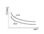
- FIG. 2 is a diagram showing the relationship between the internal resistance and the temperature in the power storage device of the vehicle in the overhead line-less traffic system.
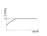
- FIG. 3 is a diagram showing the relationship between the internal resistance and the number of elapsed months when the temperature control method according to the first embodiment is performed, and
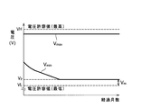
- FIG. 4 is the temperature according to the first embodiment of the present invention. It is the figure which showed the relationship between the voltage value of an electrical storage apparatus at the time of implementing a control method, and elapsed months.
- the relationship between the internal resistance R and the temperature T in the power storage device 5 will be described with reference to FIG.
- the relationship between the internal resistance R and the temperature T in the power storage device 5 is such that the internal resistance R decreases as the temperature T increases.
- the curve after deterioration in FIG. 2 when the deterioration of the power storage device 5 progresses, the curve indicating the relationship between the internal resistance R and the temperature T shifts upward from the curve before the deterioration. That is, the relationship between the deterioration in the power storage device 5 and the internal resistance R is such that the internal resistance R increases as the power storage device 5 deteriorates. Therefore, in the present embodiment, the temperature controller 6 controls the temperature of the power storage device 5 based on the relationship between the internal resistance R and the temperature T in the power storage device 5 so that the internal resistance R of the power storage device 5 is kept constant. To do.
- the minimum voltage value V min corresponding to the internal resistance R of the power storage device 5 is a predetermined voltage value (first predetermined voltage value) near the minimum voltage allowable value VL of the power storage device 5.
- first predetermined voltage value a predetermined voltage value
- V p the minimum voltage value
- the temperature control device 6 increases the temperature of the power storage device 5 gradually to increase the power storage device 5. Is maintained at a value R p corresponding to the predetermined voltage value V p (see FIG. 4).
- the internal resistance R of the power storage device 5 is maintained at the value R p corresponding to the predetermined voltage value V p , so that the minimum voltage value V min of the power storage device 5 becomes the minimum voltage allowable as shown in FIG.
- the value VL is maintained while a certain margin Vm is secured.
- the predetermined voltage value V p near the minimum voltage allowable value VL of the power storage device 5 is set to a value of 110 to 120% with respect to the minimum voltage allowable value VL, for example.
- the minimum voltage value V min corresponding to the internal resistance R of the power storage device 5 becomes the predetermined voltage value V p near the minimum voltage allowable value VL of the power storage device 5.
- the power storage device 5 is controlled to such a temperature that the minimum voltage value V min of the power storage device 5 is maintained at the predetermined voltage value V p , as the internal resistance R of the power storage device 5 increases, Even when the voltage fluctuation becomes large, the minimum voltage value V min of the power storage device 5 is maintained while securing a certain margin V m with respect to the minimum voltage allowable value VL of the power storage device 5.
- the power storage device 5 can be used over a longer period within the allowable voltage value range as compared with the conventional case, and the life of the power storage device 5 can be extended.
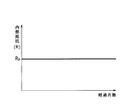
- FIG. 5 is a diagram showing a relationship between internal resistance and elapsed months when the temperature control method according to the second embodiment is performed
- FIG. 6 is a temperature control method according to the second embodiment of the present invention. It is the figure which showed the relationship between the voltage value of the electrical storage apparatus at the time of implementing, and elapsed months.
- the temperature control device 6 causes the minimum voltage value V min corresponding to the internal resistance R of the power storage device 5 to be the minimum voltage allowable value VL of the power storage device 5. controlling the temperature of the electric storage device 5 to a predetermined voltage value V p in the vicinity. Specifically, since the power storage device 5 is not deteriorated at the start of operation, the temperature control device 6 reduces the internal resistance R of the power storage device 5 to a predetermined voltage value V p by lowering the temperature of the power storage device 5. Is set to a value Rp corresponding to (see FIG. 6).
- the minimum voltage value of the power storage device 5 at the start of operation of the vehicle 1 as shown in FIG. V min is set in a state where a certain margin V m is secured with respect to the minimum voltage allowable value VL.
- the temperature control unit 6 the minimum voltage value V min of the electric storage device 5 controls the temperature of the electric storage device 5 so as to maintain the predetermined voltage value V p. Specifically, since the internal resistance R of the power storage device 5 gradually increases with deterioration (see FIG. 2), the temperature control device 6 increases the temperature of the power storage device 5 gradually to increase the power storage device 5. Is maintained at a value R p corresponding to the predetermined voltage value V p (see FIG. 6).
- the predetermined voltage value V p near the minimum voltage allowable value VL of the power storage device 5 is set to a value of 110 to 120% with respect to the minimum voltage allowable value VL, for example.
- the minimum voltage value V min corresponding to the internal resistance R of the power storage device 5 is a predetermined value near the minimum voltage allowable value VL of the power storage device 5.
- the electrical storage apparatus 5 can be used over a longer period within the range of the allowable voltage value.
- the relationship between the deterioration of the power storage device 5 and the temperature is known to be less likely to progress as the temperature of the power storage device 5 is set lower.
- the temperature of the power storage device 5 is low so that the minimum voltage value V min of the power storage device 5 becomes the predetermined voltage value V p in the vicinity of the minimum voltage allowable value VL of the power storage device 5 at the start of operation of the vehicle 1. Since it is set, the deterioration of the power storage device 5 is unlikely to proceed during a certain period (period until the temperature is increased) from the start of operation, and as a result, the life of the power storage device can be further extended.
- the maximum voltage value V max of the power storage device 5 is often a set voltage for charging, but depending on the vehicle operating environment (for example, when there is a steep slope), the maximum voltage value is during regenerative braking. V max may be obtained.
- the voltage fluctuation of the electric storage device 5 increases with the internal resistance of the battery 5 increases, gradually approaches the maximum voltage value V max is the maximum allowable voltage value VH, the result , the margin between the maximum voltage value V max and the maximum allowable voltage value VH becomes small. Therefore, in such operating environment, temperature controller 6 may control both the minimum voltage value V min and maximum voltage value V max.
- the temperature control device 6 can be controlled even with the maximum voltage value V max at the lowest voltage value V min the same way. That is, temperature control device 6 controls the temperature of power storage device 5 based on the relationship between internal resistance R and temperature T in power storage device 5 described above. As an embodiment, for example, when the maximum voltage value V max corresponding to the internal resistance R of the power storage device 5 becomes a predetermined voltage value (second predetermined voltage value) near the maximum voltage allowable value VH of the power storage device 5. , temperature controller 6, the maximum voltage value V max of the energy storage device 5 may control the temperature of the electric storage device 5 so as to maintain the predetermined voltage value.
- the temperature control device 6 determines that the maximum voltage value V max corresponding to the internal resistance R of the power storage device 5 is a predetermined value near the maximum voltage allowable value VH of the power storage device 5. controlling the temperature of the electric storage device 5 so that the voltage value and the power storage device as in operation of the vehicle 1, the temperature control unit 6, the maximum voltage value V max of the energy storage device 5 is maintained at a predetermined voltage value The temperature of 5 may be controlled.
- the predetermined voltage value in the vicinity of the maximum voltage allowable value VH of the power storage device 5 may be set to a value of 80 to 90% with respect to the maximum voltage allowable value VH, for example. .
Landscapes
- Engineering & Computer Science (AREA)
- Manufacturing & Machinery (AREA)
- Chemical & Material Sciences (AREA)
- Chemical Kinetics & Catalysis (AREA)
- Electrochemistry (AREA)
- General Chemical & Material Sciences (AREA)
- Sustainable Energy (AREA)
- Sustainable Development (AREA)
- Life Sciences & Earth Sciences (AREA)
- Power Engineering (AREA)
- Transportation (AREA)
- Mechanical Engineering (AREA)
- Electric Propulsion And Braking For Vehicles (AREA)
- Secondary Cells (AREA)
- Charge And Discharge Circuits For Batteries Or The Like (AREA)
- Control Of Electric Motors In General (AREA)
Abstract
Description
したがって、従来より、蓄電装置の電流データ、電圧データ、及び自己放電量等に基づいて蓄電装置の現在の残存容量を算出する蓄電装置用制御装置が提案されている。(例えば、特許文献1)
このように、最低電圧値Vminと最低電圧許容値VLとの間のマージンVmが小さくなると、使用状況や環境により蓄電装置の最低電圧値Vminが最低電圧許容値VLより小さくなり、これにより、インターロック機能が作動し、蓄電装置が使用できなくなる可能性が高くなる。したがって、蓄電装置を取り替えなければならず、蓄電装置を長期間にわたって使用することができなかった。
特に、車両の運用開始時において蓄電装置の最低電圧値が蓄電装置の最低電圧許容値の近傍の所定電圧値になるように蓄電装置の温度が制御されるので、運用開始時から一定期間の間は蓄電装置の劣化が進みにくくなり、その結果、蓄電装置の寿命をより延ばすことができる。
特に、車両の運用開始時において蓄電装置の最低電圧値が蓄電装置の最低電圧許容値の近傍の所定電圧値になるように蓄電装置の温度が制御されるので、車両の運用開始から一定期間の間は蓄電装置の劣化が進みにくくなり、その結果、蓄電装置の寿命をより延ばすことができる。
また、蓄電装置5は、許容電圧値として最高電圧許容値VHと最低電圧許容値VLとが予め設定されており(図4参照)、蓄電装置5の電圧値が継続して最高電圧許容値VHと最低電圧許容値VLとの間の範囲外になると、インターロック機能(図示せず)が作動し、電力を供給できないようになっている。
かかる構成により、車両1が駅に停車した際には、集電接触子4と給電接触子8とが接触することにより、地上側の充電装置から供給される電力が蓄電装置5に蓄電されることになる。
以下、本発明の第1実施形態に係る蓄電装置の温度制御方法を、図面を参照しながら説明する。図2は、架線レス交通システムの車両の蓄電装置における内部抵抗と温度との関係を示した図である。また、図3は、第1実施形態に係る温度制御方法を実施した際の内部抵抗と経過月数との関係を示した図であり、図4は、本発明の第1実施形態に係る温度制御方法を実施した際の蓄電装置の電圧値と経過月数との関係を示した図である。
図2に示すように、蓄電装置5における内部抵抗Rと温度Tとの関係は、温度Tが高くなるに伴って内部抵抗Rが小さくなるような関係になっている。また、図2の劣化後の曲線が示すように、蓄電装置5の劣化が進むと、内部抵抗Rと温度Tとの関係を示す曲線は、劣化前の曲線よりも上側にシフトする。すなわち、蓄電装置5における劣化と内部抵抗Rとの関係は、蓄電装置5の劣化が進むに伴って内部抵抗Rが大きくなるという関係になっている。
そこで、本実施形態では、蓄電装置5における内部抵抗Rと温度Tとの関係に基づいて、温度制御装置6が蓄電装置5の温度を制御することにより蓄電装置5の内部抵抗Rを一定に維持する。
本実施形態では、図3に示すように、蓄電装置5の内部抵抗Rに対応する最低電圧値Vminが蓄電装置5の最低電圧許容値VL近傍の所定電圧値(第1の所定電圧値)Vpになった際に、温度制御装置6が、蓄電装置5の最低電圧値Vminが所定電圧値Vpに維持されるように蓄電装置5の温度を制御する。詳細には、蓄電装置5は劣化に伴い内部抵抗Rが徐々に大きくなってくるので(図2参照)、温度制御装置6は、蓄電装置5の温度を徐々に高くすることにより、蓄電装置5の内部抵抗Rを所定電圧値Vpに対応する値Rpに維持する(図4参照)。
なお、本実施形態では、蓄電装置5の最低電圧許容値VL近傍の所定電圧値Vpは、例えば、最低電圧許容値VLに対して110~120%の値で設定している。
以下、本発明の第2実施形態に係る蓄電装置の温度制御方法を、図面を参照しながら説明する。図5は、第2実施形態に係る温度制御方法を実施した際の内部抵抗と経過月数との関係を示した図であり、図6は、本発明の第2実施形態に係る温度制御方法を実施した際の蓄電装置の電圧値と経過月数との関係を示した図である。
このように、蓄電装置5の内部抵抗Rを所定電圧値Vpに対応する値Rpに設定することにより、図5に示すように、車両1の運用開始時に、蓄電装置5の最低電圧値Vminが最低電圧許容値VLに対して一定のマージンVmを確保した状態で設定される。
なお、本実施形態では、蓄電装置5の最低電圧許容値VL近傍の所定電圧値Vpは、例えば、最低電圧許容値VLに対して110~120%の値で設定している。
本実施形態では、車両1の運用開始時において蓄電装置5の最低電圧値Vminが蓄電装置5の最低電圧許容値VLの近傍の所定電圧値Vpになるように蓄電装置5の温度が低く設定されるので、運用開始時から一定期間(温度を高くするまでの期間)の間は蓄電装置5の劣化が進みにくくなり、その結果、蓄電装置の寿命をより延ばすことができる。
このような運用環境では、蓄電装置5の内部抵抗が大きくなることに伴って蓄電装置5の電圧変動が大きくなると、最高電圧値Vmaxが最高電圧許容値VHに徐々に近づいていき、その結果、最高電圧値Vmaxと最高電圧許容値VHとの間のマージンが小さくなってしまう。したがって、このような運用環境において、温度制御装置6は、最低電圧値Vmin及び最高電圧値Vmaxの両方について制御を行ってもよい。
実施形態としては、例えば、蓄電装置5の内部抵抗Rに対応する最高電圧値Vmaxが蓄電装置5の最高電圧許容値VH近傍の所定電圧値(第2の所定電圧値)になった際に、温度制御装置6が、蓄電装置5の最高電圧値Vmaxが所定電圧値に維持されるように蓄電装置5の温度を制御してもよい。
2 軌道
3 台車
3a 台車の側面
4 集電接触子
5 蓄電装置
6 温度制御装置
7 支持フレーム
8 給電接触子
VL 最低電圧許容値
VH 最高電圧許容値
Vmin 蓄電装置の最低電圧値
Vmax 蓄電装置の最高電圧値
Vm 蓄電装置の最低電圧値と最低電圧許容値との間のマージン
Vp 所定電圧値
R 蓄電装置の内部抵抗
Rp Vpに対応する内部抵抗値
Claims (8)
- 蓄電装置を搭載した車両が軌道上を走行する際の前記蓄電装置の温度を制御する温度制御方法であって、
前記蓄電装置の内部抵抗に対応する最低電圧値が前記蓄電装置の最低電圧許容値近傍の第1の所定電圧値になった際に、前記蓄電装置の前記最低電圧値が前記第1の所定電圧値に維持されるような温度に前記蓄電装置を制御することを特徴とする温度制御方法。 - 前記蓄電装置の内部抵抗に対応する最高電圧値が前記蓄電装置の最高電圧許容値近傍の第2の所定電圧値になった際に、前記蓄電装置の前記最高電圧値が前記第2の所定電圧値に維持されるような温度に前記蓄電装置を制御することを特徴とする請求項1の温度制御方法。
- 蓄電装置を搭載した車両が軌道上を走行する際の前記蓄電装置の温度を制御する温度制御方法であって、
前記車両の運用開始時に、前記蓄電装置の内部抵抗に対応する最低電圧値が前記蓄電装置の最低電圧許容値近傍の第1の所定電圧値になるような温度に前記蓄電装置を制御し、車両の運用中、前記蓄電装置の前記最低電圧値が前記第1の所定電圧値に維持されるような温度に前記蓄電装置を制御することを特徴とする温度制御方法。 - 前記車両の運用開始時に、前記蓄電装置の内部抵抗に対応する最高電圧値が前記蓄電装置の最高電圧許容値近傍の第2の所定電圧値になるような温度に前記蓄電装置を制御し、車両の運用中、前記蓄電装置の前記最高電圧値が前記第2の所定電圧値に維持されるような温度に前記蓄電装置を制御することを特徴とする請求項3に記載の温度制御方法。
- 蓄電装置を搭載した車両が軌道上を走行するように構成された架線レス交通システムにおいて、
前記蓄電装置が、温度制御装置を備えており、該温度制御装置は、前記蓄電装置の内部抵抗に対応する最低電圧値が前記蓄電装置の最低電圧許容値近傍の第1の所定電圧値になった際に、前記蓄電装置の前記最低電圧値が前記第1の所定電圧値に維持されるような温度に前記蓄電装置を制御するようになっていることを特徴とする架線レス交通システム。 - 前記温度制御装置は、前記蓄電装置の内部抵抗に対応する最高電圧値が前記蓄電装置の最高電圧許容値近傍の第2の所定電圧値になった際に、前記蓄電装置の前記最高電圧値が前記第2の所定電圧値に維持されるような温度に前記蓄電装置を制御するようになっていることを特徴とする請求項5に記載の架線レス交通システム。
- 蓄電装置を搭載した車両が軌道上を走行するように構成された架線レス交通システムにおいて、
前記蓄電装置が、温度制御装置を備えており、該温度制御装置が、前記車両の運用開始時に、前記蓄電装置の内部抵抗に対応する最低電圧値が前記蓄電装置の最低電圧許容値近傍の第1の所定電圧値になるような温度に前記蓄電装置を制御し、車両の運用中、前記蓄電装置の前記最低電圧値が前記第1の所定電圧値に維持されるような温度に前記蓄電装置を制御するようになっていることを特徴とする架線レス交通システム。 - 前記温度制御装置が、前記車両の運用開始時に、前記蓄電装置の内部抵抗に対応する最高電圧値が前記蓄電装置の最高電圧許容値近傍の第2の所定電圧値になるような温度に前記蓄電装置を制御し、車両の運用中、前記蓄電装置の前記最高電圧値が前記第2の所定電圧値に維持されるような温度に前記蓄電装置を制御するようになっていることを特徴とする請求項7に記載の架線レス交通システム。
Priority Applications (3)
| Application Number | Priority Date | Filing Date | Title |
|---|---|---|---|
| US13/139,146 US9184473B2 (en) | 2009-03-10 | 2009-09-17 | Temperature control method and temperature controller |
| SG2011043353A SG172139A1 (en) | 2009-03-10 | 2009-09-17 | Temperature control method and temperature controller |
| CN200980153398.XA CN102271953B (zh) | 2009-03-10 | 2009-09-17 | 温度控制方法和温度控制器 |
Applications Claiming Priority (2)
| Application Number | Priority Date | Filing Date | Title |
|---|---|---|---|
| JP2009-056357 | 2009-03-10 | ||
| JP2009056357A JP4823328B2 (ja) | 2009-03-10 | 2009-03-10 | 温度制御方法及び温度制御装置 |
Publications (1)
| Publication Number | Publication Date |
|---|---|
| WO2010103685A1 true WO2010103685A1 (ja) | 2010-09-16 |
Family
ID=42727986
Family Applications (1)
| Application Number | Title | Priority Date | Filing Date |
|---|---|---|---|
| PCT/JP2009/066219 Ceased WO2010103685A1 (ja) | 2009-03-10 | 2009-09-17 | 温度制御方法及び温度制御装置 |
Country Status (6)
| Country | Link |
|---|---|
| US (1) | US9184473B2 (ja) |
| JP (1) | JP4823328B2 (ja) |
| CN (1) | CN102271953B (ja) |
| SG (1) | SG172139A1 (ja) |
| TW (1) | TWI400855B (ja) |
| WO (1) | WO2010103685A1 (ja) |
Citations (2)
| Publication number | Priority date | Publication date | Assignee | Title |
|---|---|---|---|---|
| JP2007202335A (ja) * | 2006-01-27 | 2007-08-09 | Mitsubishi Heavy Ind Ltd | 交通システム、車両、交通システムの充電方法及び充電管理方法 |
| JP2008245485A (ja) * | 2007-03-29 | 2008-10-09 | Hitachi Ltd | 車両制御システム |
Family Cites Families (9)
| Publication number | Priority date | Publication date | Assignee | Title |
|---|---|---|---|---|
| US4313080A (en) * | 1978-05-22 | 1982-01-26 | Battery Development Corporation | Method of charge control for vehicle hybrid drive batteries |
| US6462507B2 (en) * | 1998-08-07 | 2002-10-08 | Okc Products, Inc. | Apparatus and method for initial charging, self-starting, and operation of a power supply with an intermittent and/or variable energy source and a rechargeable energy storage device |
| JP3876979B2 (ja) * | 2002-03-18 | 2007-02-07 | 三菱自動車工業株式会社 | バッテリ制御装置 |
| TW554847U (en) | 2002-11-06 | 2003-09-21 | Guan-Yuan Lai | Temperature control device for vehicular interior |
| US7234552B2 (en) * | 2003-09-19 | 2007-06-26 | Ford Global Technologies, Llc | Method for heating a battery in a hybrid electric vehicle |
| JP2005130559A (ja) | 2003-10-21 | 2005-05-19 | Panasonic Ev Energy Co Ltd | 電池制御装置および方法、並びに電動車両 |
| CN100490271C (zh) * | 2005-07-22 | 2009-05-20 | 鸿富锦精密工业(深圳)有限公司 | 电池省电系统及方法 |
| US7638980B2 (en) * | 2006-06-07 | 2009-12-29 | Gm Global Technology Operations, Inc. | Method and apparatus for determining the effect of temperature upon life expectancy of an electric energy storage device in a hybrid electric vehicle |
| JP5076378B2 (ja) * | 2006-07-03 | 2012-11-21 | マツダ株式会社 | バッテリの温度制御装置 |
-
2009
- 2009-03-10 JP JP2009056357A patent/JP4823328B2/ja not_active Expired - Fee Related
- 2009-09-03 TW TW98129747A patent/TWI400855B/zh not_active IP Right Cessation
- 2009-09-17 CN CN200980153398.XA patent/CN102271953B/zh not_active Expired - Fee Related
- 2009-09-17 US US13/139,146 patent/US9184473B2/en not_active Expired - Fee Related
- 2009-09-17 SG SG2011043353A patent/SG172139A1/en unknown
- 2009-09-17 WO PCT/JP2009/066219 patent/WO2010103685A1/ja not_active Ceased
Patent Citations (2)
| Publication number | Priority date | Publication date | Assignee | Title |
|---|---|---|---|---|
| JP2007202335A (ja) * | 2006-01-27 | 2007-08-09 | Mitsubishi Heavy Ind Ltd | 交通システム、車両、交通システムの充電方法及び充電管理方法 |
| JP2008245485A (ja) * | 2007-03-29 | 2008-10-09 | Hitachi Ltd | 車両制御システム |
Also Published As
| Publication number | Publication date |
|---|---|
| CN102271953B (zh) | 2014-02-19 |
| JP2010213444A (ja) | 2010-09-24 |
| JP4823328B2 (ja) | 2011-11-24 |
| US9184473B2 (en) | 2015-11-10 |
| CN102271953A (zh) | 2011-12-07 |
| TW201034341A (en) | 2010-09-16 |
| US20120019060A1 (en) | 2012-01-26 |
| TWI400855B (zh) | 2013-07-01 |
| SG172139A1 (en) | 2011-07-28 |
Similar Documents
| Publication | Publication Date | Title |
|---|---|---|
| JP4576465B2 (ja) | 架線レス交通車両の充電方法及び充電システム | |
| JP2007236196A (ja) | バッテリ駆動の鉄道列車 | |
| JP2012161240A (ja) | 電池駆動車両のパワーフロー制御方法および制御装置 | |
| WO2015115541A1 (ja) | 電気車制御装置 | |
| JP4244060B2 (ja) | 移動体 | |
| JP2009254069A (ja) | 鉄道車両の制御方法および装置 | |
| JP5751764B2 (ja) | クレーン制御装置、及びクレーン装置 | |
| JP7212075B2 (ja) | 自動化コンテナターミナルのagv充電方法及びシステム | |
| JP5410728B2 (ja) | クレーン装置およびクレーン装置の制御方法 | |
| JP2006034041A (ja) | き電系統電力貯蔵システムの制御装置 | |
| JP5514459B2 (ja) | 充電システム | |
| JP5501594B2 (ja) | クレーン装置およびクレーン装置の制御方法 | |
| JP4823328B2 (ja) | 温度制御方法及び温度制御装置 | |
| JP4907262B2 (ja) | 電気車両の制御装置 | |
| JP2008154355A (ja) | 蓄電設備 | |
| CN103339820B (zh) | 电力供给装置以及供给电力控制方法 | |
| CN103534129B (zh) | 用于管理车辆的电制动的设备和方法 | |
| JP4670827B2 (ja) | 車両制御システム | |
| JP2008074180A (ja) | 電力貯蔵システム | |
| JP4495003B2 (ja) | 鉄道車両の蓄電装置暖機方法及び装置 | |
| JP4709654B2 (ja) | 交通システム | |
| JP2008072878A (ja) | 電気車制御装置 | |
| JPWO2010013314A1 (ja) | 直列型ハイブリッド鉄道車両 | |
| KR20130035795A (ko) | 무가선 저상 트램의 배터리 충전상태 관리방법 | |
| JP2011526562A (ja) | 電気貯蔵の方法およびシステム |
Legal Events
| Date | Code | Title | Description |
|---|---|---|---|
| WWE | Wipo information: entry into national phase |
Ref document number: 200980153398.X Country of ref document: CN |
|
| 121 | Ep: the epo has been informed by wipo that ep was designated in this application |
Ref document number: 09841510 Country of ref document: EP Kind code of ref document: A1 |
|
| WWE | Wipo information: entry into national phase |
Ref document number: 13139146 Country of ref document: US |
|
| NENP | Non-entry into the national phase |
Ref country code: DE |
|
| 122 | Ep: pct application non-entry in european phase |
Ref document number: 09841510 Country of ref document: EP Kind code of ref document: A1 |