WO2010100848A1 - 符号化器、復号化器及び符号化方法 - Google Patents
符号化器、復号化器及び符号化方法 Download PDFInfo
- Publication number
- WO2010100848A1 WO2010100848A1 PCT/JP2010/001099 JP2010001099W WO2010100848A1 WO 2010100848 A1 WO2010100848 A1 WO 2010100848A1 JP 2010001099 W JP2010001099 W JP 2010001099W WO 2010100848 A1 WO2010100848 A1 WO 2010100848A1
- Authority
- WO
- WIPO (PCT)
- Prior art keywords
- information
- coding rate
- ldpc
- parity
- time
- Prior art date
- Legal status (The legal status is an assumption and is not a legal conclusion. Google has not performed a legal analysis and makes no representation as to the accuracy of the status listed.)
- Ceased
Links
Images


Classifications
-
- H—ELECTRICITY
- H03—ELECTRONIC CIRCUITRY
- H03M—CODING; DECODING; CODE CONVERSION IN GENERAL
- H03M13/00—Coding, decoding or code conversion, for error detection or error correction; Coding theory basic assumptions; Coding bounds; Error probability evaluation methods; Channel models; Simulation or testing of codes
- H03M13/03—Error detection or forward error correction by redundancy in data representation, i.e. code words containing more digits than the source words
- H03M13/033—Theoretical methods to calculate these checking codes
- H03M13/036—Heuristic code construction methods, i.e. code construction or code search based on using trial-and-error
-
- H—ELECTRICITY
- H03—ELECTRONIC CIRCUITRY
- H03M—CODING; DECODING; CODE CONVERSION IN GENERAL
- H03M13/00—Coding, decoding or code conversion, for error detection or error correction; Coding theory basic assumptions; Coding bounds; Error probability evaluation methods; Channel models; Simulation or testing of codes
- H03M13/03—Error detection or forward error correction by redundancy in data representation, i.e. code words containing more digits than the source words
- H03M13/05—Error detection or forward error correction by redundancy in data representation, i.e. code words containing more digits than the source words using block codes, i.e. a predetermined number of check bits joined to a predetermined number of information bits
- H03M13/11—Error detection or forward error correction by redundancy in data representation, i.e. code words containing more digits than the source words using block codes, i.e. a predetermined number of check bits joined to a predetermined number of information bits using multiple parity bits
- H03M13/1102—Codes on graphs and decoding on graphs, e.g. low-density parity check [LDPC] codes
- H03M13/1105—Decoding
- H03M13/1111—Soft-decision decoding, e.g. by means of message passing or belief propagation algorithms
-
- H—ELECTRICITY
- H03—ELECTRONIC CIRCUITRY
- H03M—CODING; DECODING; CODE CONVERSION IN GENERAL
- H03M13/00—Coding, decoding or code conversion, for error detection or error correction; Coding theory basic assumptions; Coding bounds; Error probability evaluation methods; Channel models; Simulation or testing of codes
- H03M13/03—Error detection or forward error correction by redundancy in data representation, i.e. code words containing more digits than the source words
- H03M13/05—Error detection or forward error correction by redundancy in data representation, i.e. code words containing more digits than the source words using block codes, i.e. a predetermined number of check bits joined to a predetermined number of information bits
- H03M13/11—Error detection or forward error correction by redundancy in data representation, i.e. code words containing more digits than the source words using block codes, i.e. a predetermined number of check bits joined to a predetermined number of information bits using multiple parity bits
- H03M13/1102—Codes on graphs and decoding on graphs, e.g. low-density parity check [LDPC] codes
- H03M13/1148—Structural properties of the code parity-check or generator matrix
- H03M13/1154—Low-density parity-check convolutional codes [LDPC-CC]
-
- H—ELECTRICITY
- H03—ELECTRONIC CIRCUITRY
- H03M—CODING; DECODING; CODE CONVERSION IN GENERAL
- H03M13/00—Coding, decoding or code conversion, for error detection or error correction; Coding theory basic assumptions; Coding bounds; Error probability evaluation methods; Channel models; Simulation or testing of codes
- H03M13/25—Error detection or forward error correction by signal space coding, i.e. adding redundancy in the signal constellation, e.g. Trellis Coded Modulation [TCM]
- H03M13/255—Error detection or forward error correction by signal space coding, i.e. adding redundancy in the signal constellation, e.g. Trellis Coded Modulation [TCM] with Low Density Parity Check [LDPC] codes
-
- H—ELECTRICITY
- H03—ELECTRONIC CIRCUITRY
- H03M—CODING; DECODING; CODE CONVERSION IN GENERAL
- H03M13/00—Coding, decoding or code conversion, for error detection or error correction; Coding theory basic assumptions; Coding bounds; Error probability evaluation methods; Channel models; Simulation or testing of codes
- H03M13/37—Decoding methods or techniques, not specific to the particular type of coding provided for in groups H03M13/03 - H03M13/35
- H03M13/3723—Decoding methods or techniques, not specific to the particular type of coding provided for in groups H03M13/03 - H03M13/35 using means or methods for the initialisation of the decoder
-
- H—ELECTRICITY
- H03—ELECTRONIC CIRCUITRY
- H03M—CODING; DECODING; CODE CONVERSION IN GENERAL
- H03M13/00—Coding, decoding or code conversion, for error detection or error correction; Coding theory basic assumptions; Coding bounds; Error probability evaluation methods; Channel models; Simulation or testing of codes
- H03M13/63—Joint error correction and other techniques
- H03M13/635—Error control coding in combination with rate matching
- H03M13/6362—Error control coding in combination with rate matching by puncturing
- H03M13/6368—Error control coding in combination with rate matching by puncturing using rate compatible puncturing or complementary puncturing
- H03M13/6393—Rate compatible low-density parity check [LDPC] codes
-
- H—ELECTRICITY
- H03—ELECTRONIC CIRCUITRY
- H03M—CODING; DECODING; CODE CONVERSION IN GENERAL
- H03M13/00—Coding, decoding or code conversion, for error detection or error correction; Coding theory basic assumptions; Coding bounds; Error probability evaluation methods; Channel models; Simulation or testing of codes
- H03M13/65—Purpose and implementation aspects
- H03M13/6508—Flexibility, adaptability, parametrability and configurability of the implementation
- H03M13/6516—Support of multiple code parameters, e.g. generalized Reed-Solomon decoder for a variety of generator polynomials or Galois fields
-
- H—ELECTRICITY
- H04—ELECTRIC COMMUNICATION TECHNIQUE
- H04L—TRANSMISSION OF DIGITAL INFORMATION, e.g. TELEGRAPHIC COMMUNICATION
- H04L1/00—Arrangements for detecting or preventing errors in the information received
- H04L1/0001—Systems modifying transmission characteristics according to link quality, e.g. power backoff
- H04L1/0009—Systems modifying transmission characteristics according to link quality, e.g. power backoff by adapting the channel coding
-
- H—ELECTRICITY
- H04—ELECTRIC COMMUNICATION TECHNIQUE
- H04L—TRANSMISSION OF DIGITAL INFORMATION, e.g. TELEGRAPHIC COMMUNICATION
- H04L1/00—Arrangements for detecting or preventing errors in the information received
- H04L1/004—Arrangements for detecting or preventing errors in the information received by using forward error control
- H04L1/0041—Arrangements at the transmitter end
-
- H—ELECTRICITY
- H04—ELECTRIC COMMUNICATION TECHNIQUE
- H04L—TRANSMISSION OF DIGITAL INFORMATION, e.g. TELEGRAPHIC COMMUNICATION
- H04L1/00—Arrangements for detecting or preventing errors in the information received
- H04L1/004—Arrangements for detecting or preventing errors in the information received by using forward error control
- H04L1/0045—Arrangements at the receiver end
-
- H—ELECTRICITY
- H04—ELECTRIC COMMUNICATION TECHNIQUE
- H04L—TRANSMISSION OF DIGITAL INFORMATION, e.g. TELEGRAPHIC COMMUNICATION
- H04L1/00—Arrangements for detecting or preventing errors in the information received
- H04L1/004—Arrangements for detecting or preventing errors in the information received by using forward error control
- H04L1/0056—Systems characterized by the type of code used
- H04L1/0057—Block codes
- H04L1/0058—Block-coded modulation
-
- H—ELECTRICITY
- H04—ELECTRIC COMMUNICATION TECHNIQUE
- H04L—TRANSMISSION OF DIGITAL INFORMATION, e.g. TELEGRAPHIC COMMUNICATION
- H04L1/00—Arrangements for detecting or preventing errors in the information received
- H04L1/004—Arrangements for detecting or preventing errors in the information received by using forward error control
- H04L1/0056—Systems characterized by the type of code used
- H04L1/0059—Convolutional codes
Definitions
- the present invention relates to an encoder, a decoder, and an encoding method using a low density parity check convolutional code (LDPC-CC: Low Density Parity Check-Convolutional Codes) that can support a plurality of coding rates.
- LDPC-CC Low Density Parity Check-Convolutional Codes
- LDPC low density parity check
- the LDPC code is an error correction code defined by a low-density parity check matrix H.
- the LDPC code is a block code having a block length equal to the number N of columns of the parity check matrix H.
- Non-Patent Document 1, Non-Patent Document 2, Non-Patent Document 3, and Non-Patent Document 4 propose a random LDPC code, Array LDPC code, and QC-LDPC code (QC: Quasi-Cyclic).
- LDPC-BC Low-Density Parity-Check Block Code
- LDPC-CC Low-Density Parity-Check Convolutional Codes
- LDPC-CC is a convolutional code defined by a low-density parity check matrix.
- M represents the memory length in the LDPC-CC
- n represents the length of the code word in the LDPC-CC.
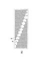
- 1 is arranged only in the diagonal term of the matrix and its neighboring elements, the lower left and upper right elements of the matrix are zero, and the parallelogram There is a feature that it is a matrix of shape.
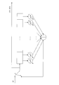
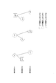
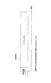
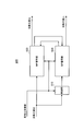
- the LDPC-CC encoder defined by the parity check matrix H T [0, n] T Is represented in FIG.
- the LDPC-CC encoder includes a shift register M + 1 with a bit length c and a mod2 adder (exclusive OR operator).
- the LDPC-CC encoder is realized by a very simple circuit compared to a circuit that performs multiplication of a generator matrix and an LDPC-BC encoder that performs an operation based on the backward (forward) substitution method.
- FIG. 2 shows a convolutional code encoder, it is not necessary to divide the information sequence into fixed-length blocks and encode it, and an information sequence of an arbitrary length can be encoded.
- Non-Patent Document 8 shows that puncturing is used to support a plurality of coding rates.
- a base code that is, a mother code
- an encoded sequence in the mother code is created, and transmission is not performed from the encoded sequence (puncture).
- Select a bit By changing the number of bits that are not transmitted, a plurality of coding rates are supported.
- both the encoder and the decoder can cope with all coding rates by using the encoder and decoder for the mother code, which has the advantage that the operation scale (circuit scale) can be reduced. .
- a method for dealing with a plurality of coding rates there is a method of preparing different codes for each coding rate (Distributed Codes).
- distributed Codes distributed Codes
- a method of dealing with a plurality of coding rates with a plurality of codes is general because of the flexibility of easily configuring various code lengths and coding rates.
- the operation scale circuit scale
- the data reception quality is very good as compared with the case where a plurality of coding rates are supported by puncturing.
- the operation scale of the encoder and the decoder is ensured while ensuring the reception quality of the data by preparing a plurality of codes to cope with a plurality of coding rates.
- LDPC code generation methods that can reduce the amount of data, and if an LDPC code creation method that can achieve this is established, improvement of data reception quality and reduction of the computation scale, which have been difficult to achieve until now, have been achieved. Coexistence is possible.
- LDPC-CC is a kind of convolutional code
- termination and tail biting are required to ensure reliability in decoding information bits.
- sufficient studies have not been made on the LDPC-CC and its encoder and decoder that can reduce the number of terminations as much as possible while ensuring the data reception quality.
- An object of the present invention is to prevent deterioration in error correction capability and avoid reduction in information transmission efficiency even when termination is performed in an encoder and a decoder using LDPC-CC.
- An encoder, a decoder, and an encoding method are provided.
- An encoder is an encoder that performs LDPC-CC encoding, and includes a termination sequence transmitted after being added to the tail of the information sequence according to the information length and coding rate of the information sequence.
- a determination means for determining a sequence length; and LDPC-CC encoding is performed on the information sequence and a known information sequence necessary for generating the termination sequence for the determined sequence length, and a parity sequence is calculated And a calculating means.
- the decoder of the present invention is a decoder that decodes LDPC-CC using reliability propagation, and includes a coding rate, a sequence length of a termination sequence transmitted after being added to the tail of an information sequence, and And a decoding unit that performs reliability propagation decoding on the information sequence based on the coding rate and the termination sequence length.
- the encoding method of the present invention determines a sequence length of a termination sequence to be transmitted by adding to the tail of the information sequence according to an information length and a coding rate of the information sequence, and determines the information sequence and
- the parity information is calculated by applying LDPC-CC coding to the known information sequence necessary for generating the termination sequence for the sequence length.
- the encoder the decoder and the encoding method of the present invention, even when termination is performed, the error correction capability is not deteriorated and a decrease in information transmission efficiency can be avoided.
- the figure which shows the parity check matrix of LDPC-CC The figure which shows the structure of a LDPC-CC encoder The figure which shows an example of a structure of the parity check matrix of LDPC-CC of time-varying period 4 The figure which shows the structure of the parity check polynomial and parity check matrix H of LDPC-CC of time-varying period 3 The figure which shows the relationship of the reliability propagation
- FIG. 9 is a block diagram showing a main configuration of a parity operation unit according to the third embodiment.
- FIG. 9 is a block diagram showing another main configuration of the encoder according to Embodiment 3.
- FIG. 9 is a block diagram showing a main configuration of a decoder according to the third embodiment.
- FIG. Diagram showing an example of transmission format The figure which shows an example of a structure of the communication apparatus carrying the encoder which concerns on Embodiment 3.
- FIG. Diagram showing an example of transmission format The figure which shows an example of a structure of the communication apparatus carrying the decoder which concerns on Embodiment 3.
- FIG. The figure which shows an example of the relationship between information size and the number of terminations
- the figure which shows an example of the relationship between information size and the number of terminations The block diagram which shows the principal part structure of the communication apparatus carrying the encoder which concerns on Embodiment 5 of this invention. Diagram for explaining how to determine the termination sequence length Diagram for explaining how to determine the termination sequence length Diagram showing an example of transmission format
- FIG. 7 is a block diagram showing a main configuration of a communication apparatus equipped with a decoder according to the fifth embodiment.
- the figure which shows an example of the flow of the information between the communication apparatus which mounts an encoder, and the communication apparatus which mounts a decoder The figure which shows an example of the flow of the information between the communication apparatus which mounts an encoder, and the communication apparatus which mounts a decoder
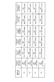
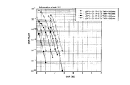
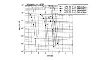
- the figure which shows an example of the correspondence table which shows the relationship between information size and the number of terminations The figure which shows the BER / BLER characteristic at the time of adding a termination series to the information series whose information size is 512 bits
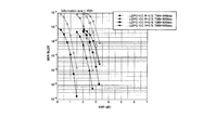
- the figure which shows the BER / BLER characteristic at the time of adding a termination series to the information series whose information size is 1024 bits
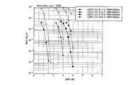
- the figure which shows the BER / BLER characteristic at the time of adding a termination series to the information series whose information size is 2048 bits
- FIG. 9 is a block diagram showing a main configuration of a communication apparatus equipped with a decoder according to the sixth embodiment.
- the block diagram which shows the principal part structure of the encoder based on Embodiment 7 of this invention
- the block diagram which shows the principal part structure of the decoder which concerns on Embodiment 7.
- the block diagram which shows the principal part structure of the encoder which concerns on Embodiment 8 of this invention.
- LDPC-CC with good characteristics The LDPC-CC having a time varying period g with good characteristics will be described below.
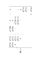
- Formulas (1-1) to (1-4) are considered as parity check polynomials for LDPC-CC with a time-varying period of 4.
- X (D) is a polynomial expression of data (information)
- P (D) is a polynomial expression of parity.
- the parity check polynomial is such that there are four terms in each of X (D) and P (D). This is because it is preferable to obtain four terms.
- a1, a2, a3, and a4 are integers (however, a1 ⁇ a2 ⁇ a3 ⁇ a4, and all of a1 to a4 are different).
- X, Y,. B1, b2, b3, and b4 are integers (where b1 ⁇ b2 ⁇ b3 ⁇ b4).
- the parity check polynomial of equation (1-1) is referred to as “check equation # 1”, and a sub-matrix based on the parity check polynomial of equation (1-1) is defined as a first sub-matrix H 1 .
- A1, A2, A3, and A4 are integers (however, A1 ⁇ A2 ⁇ A3 ⁇ A4).
- B1, B2, B3, and B4 are integers (B1 ⁇ B2 ⁇ B3 ⁇ B4).
- check equation # 2 the sub-matrix based on a parity check polynomial of equation (1-2), the second sub-matrix H 2.
- Equation (1-3) ⁇ 1, ⁇ 2, ⁇ 3, and ⁇ 4 are integers (where ⁇ 1 ⁇ ⁇ 2 ⁇ ⁇ 3 ⁇ ⁇ 4). ⁇ 1, ⁇ 2, ⁇ 3, and ⁇ 4 are integers (where ⁇ 1 ⁇ ⁇ 2 ⁇ ⁇ 3 ⁇ ⁇ 4).
- the parity check polynomial of equation (1-3) is called “check equation # 3”, and the sub-matrix based on the parity check polynomial of equation (1-3) is referred to as a third sub-matrix H 3 .
- Equation (1-4) E1, E2, E3, and E4 are integers (however, E1 ⁇ E2 ⁇ E3 ⁇ E4). Further, F1, F2, F3, and F4 are integers (where F1 ⁇ F2 ⁇ F3 ⁇ F4).
- the parity check polynomial of equation (1-4) is called “check equation # 4”, and the sub-matrix based on the parity check polynomial of equation (1-4) is referred to as a fourth sub-matrix H 4 .
- an LDPC-CC with a time varying period of 4 that generates a parity check matrix as shown in FIG. 3 from the first sub-matrix H 1 , the second sub-matrix H 2 , the third sub-matrix H 3 , and the fourth sub-matrix H 4 think about.
- each order The remainder k obtained by dividing (a1, a2, a3, a4) by 4 becomes (0, 3, 2, 1), and the remainder (k) 0, 1, 2, 3 is one by one in the four coefficient sets. To be included.
- a regular LDPC code can be formed in which the column weight of the parity check matrix H composed of the equations (1-1) to (1-4) is 4 in all columns.
- the regular LDPC code is an LDPC code defined by a parity check matrix in which each column weight is constant, and has characteristics that characteristics are stable and an error floor is difficult to occur.
- the column weight is 4, the characteristics are good, so that LDPC-CC with good reception performance can be obtained by generating LDPC-CC as described above.
- Table 1 is an example of LDPC-CC (LDPC-CC # 1 to # 3) having a time-varying period of 4 and a coding rate of 1 ⁇ 2, in which the condition regarding the “remainder” is satisfied.
- an LDPC-CC with a time varying period of 4 is defined by four parity check polynomials of “check polynomial # 1”, “check polynomial # 2”, “check polynomial # 3”, and “check polynomial # 4”.
- the case where the coding rate is 1 ⁇ 2 has been described as an example.
- the coding rate is (n ⁇ 1) / n
- the information X1 (D), X2 (D) In each of the four coefficient sets in 1 (D), if the above-mentioned condition relating to the “remainder” is satisfied, it becomes a regular LDPC code, and good reception quality can be obtained.
- equations (2-1) and (2-2) are considered.
- X (D) is a polynomial expression of data (information)
- P (D) is a polynomial expression of parity.
- the parity check polynomial is such that four terms exist in each of X (D) and P (D). This is because it is preferable to obtain four terms in order to obtain.
- a1, a2, a3, and a4 are integers (where a1 ⁇ a2 ⁇ a3 ⁇ a4).
- B1, b2, b3, and b4 are integers (where b1 ⁇ b2 ⁇ b3 ⁇ b4).
- the parity check polynomial of equation (2-1) is referred to as “check equation # 1”, and the sub-matrix based on the parity check polynomial of equation (2-1) is defined as a first sub-matrix H 1 .
- A1, A2, A3, and A4 are integers (however, A1 ⁇ A2 ⁇ A3 ⁇ A4).
- B1, B2, B3, and B4 are integers (B1 ⁇ B2 ⁇ B3 ⁇ B4).
- check equation # 2 the sub-matrix based on a parity check polynomial of equation (2-2), the second sub-matrix H 2.
- each order The remainder k obtained by dividing (a1, a2, a3, a4) by 4 becomes (0, 3, 2, 1), and the remainder (k) 0, 1, 2, 3 is one by one in the four coefficient sets. To be included.
- a regular LDPC code can be formed in which the column weights of the parity check matrix H composed of equations (2-1) and (2-2) are 4 in all columns.
- the regular LDPC code is an LDPC code defined by a parity check matrix in which each column weight is constant, and has characteristics that characteristics are stable and an error floor is difficult to occur.
- the row weight is 8
- the characteristics are good, so that the LDPC-CC that can further improve the reception performance can be obtained by generating the LDPC-CC as described above.
- Table 2 shows an example of LDPC-CC (LDPC-CC # 1, # 2) with a time-varying period of 2 and a coding rate of 1 ⁇ 2, in which the condition regarding the “remainder” is satisfied.
- an LDPC-CC with a time-varying period of 2 is defined by two parity check polynomials of “check polynomial # 1” and “check polynomial # 2”.
- Formulas (3-1) to (3-3) are considered as parity check polynomials for LDPC-CC with a time-varying period of 3.
- X (D) is a polynomial expression of data (information)
- P (D) is a polynomial expression of parity.
- the parity check polynomial is such that three terms exist in each of X (D) and P (D).
- a1, a2, and a3 are integers (where a1 ⁇ a2 ⁇ a3).
- B1, b2, and b3 are integers (where b1 ⁇ b2 ⁇ b3).
- the parity check polynomial of equation (3-1) is referred to as “check equation # 1”, and the sub-matrix based on the parity check polynomial of equation (3-1) is referred to as a first sub-matrix H 1 .
- equation (3-2) A1, A2, and A3 are integers (where A1 ⁇ A2 ⁇ A3).
- B1, B2, and B3 are integers (B1 ⁇ B2 ⁇ B3).
- check equation # 2 the sub-matrix based on a parity check polynomial of equation (3-2), the second sub-matrix H 2.
- ⁇ 1, ⁇ 2, and ⁇ 3 are integers (where ⁇ 1 ⁇ ⁇ 2 ⁇ ⁇ 3).
- ⁇ 1, ⁇ 2, and ⁇ 3 are integers (where ⁇ 1 ⁇ ⁇ 2 ⁇ ⁇ 3).
- the parity check polynomial of equation (3-3) is called “check equation # 3”, and the sub-matrix based on the parity check polynomial of equation (3-3) is referred to as a third sub-matrix H 3 .
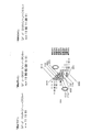
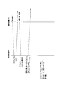
- FIG. 4A shows a configuration of an LDPC-CC parity check polynomial and parity check matrix H of time-varying period 3.
- the example of the LDPC-CC with the time-varying period 3 shown in FIG. 4A is the above-mentioned condition relating to the “remainder”, that is, (a1% 3, a2% 3, a3% 3), (b1% 3, b2% 3, b3% 3), (A1% 3, A2% 3, A3% 3), (B1% 3, B2% 3, B3% 3), ( ⁇ 1% 3, ⁇ 2% 3, ⁇ 3% 3), ( ⁇ 1% 3, ⁇ 2% 3, ⁇ 3% 3) are (0, 1, 2), (0, 2, 1), (1, 0, 2), (1, 2, 0), (2, 0 1), (2, 1, 0) is satisfied.
- “1” in the region 6502 in which the remainder is 1 in the coefficient of “check equation # 1” is a region in which the remainder is 2 in the coefficient of “check equation # 2” in the column calculation of the column 6509 in BP decoding.
- the reliability is propagated from “1” of 6507 “1” and “1” of the region 6508 in which the remainder is 0 in the coefficient of “checking formula # 3”.
- “1” in the region 6503 in which the remainder is 2 in the coefficient of “check equation # 1” is a region in which the remainder is 0 in the coefficient of “check equation # 2” in the column calculation of the column 6512 in BP decoding.
- the reliability is propagated from “1” of 6510 “1” and “1” of the region 6511 in which the remainder is 1 in the coefficient of “check equation # 3”.
- FIG. 4B shows the relationship of reliability propagation between the terms relating to X (D) of “checking formula # 1” to “checking formula # 3” in FIG. 4A.
- the terms (a3, A3, ⁇ 3) enclosed by squares indicate coefficients with a remainder of 0 divided by 3. Further, the terms (a2, A2, ⁇ 1) surrounded by circles indicate a coefficient whose remainder is 1 after dividing by 3. In addition, the terms (a1, A1, ⁇ 2) surrounded by rhombuses indicate coefficients with a remainder of 2 divided by 3.
- FIG. 4B shows the relationship of reliability propagation between the terms related to X (D) of “checking formula # 1” to “checking formula # 3”, but the same applies to the terms related to P (D). I can say that.
- the reliability is propagated to the “checking formula # 1” from the coefficients having the remainders of 0, 1, and 2 divided by 3 among the coefficients of the “checking formula # 2”. That is, the reliability is propagated to the “checking formula # 1” from the coefficients of the “checking formula # 2” that are all different in the remainder after division by 3. Therefore, all the reliability levels with low correlation are propagated to “check formula # 1”.
- the reliability is propagated to the “checking formula # 2” from the coefficients of the “checking formula # 1” whose remainders obtained by dividing by 3 are 0, 1, and 2. That is, the reliability is propagated to the “check equation # 2” from the coefficients of the “check equation # 1”, all of which have different remainders after division by 3. Also, the reliability is propagated to “check formula # 2” from the coefficients of which the remainder obtained by dividing by 3 is 0, 1, and 2 among the coefficients of “check formula # 3”. That is, the reliability is propagated to the “check equation # 2” from the coefficients of the “check equation # 3”, all of which have different remainders after division by 3.
- the reliability is propagated to the “checking formula # 3” from the coefficients of which the remainder obtained by dividing by 3 is 0, 1, 2, among the coefficients of the “checking formula # 1”. That is, the reliability is propagated to the “check equation # 3” from the coefficients of the “check equation # 1”, all of which have different remainders after division by 3. Also, the reliability is propagated to “check formula # 3” from the coefficients of which the remainder obtained by dividing by 3 becomes 0, 1 and 2 among the coefficients of “check formula # 2”. That is, the reliability is propagated to the “checking formula # 3” from the coefficients of the “checking formula # 2”, all of which have different remainders after division by 3.
- the reliability is always ensured in all column operations. Since it is propagated, the reliability can be propagated efficiently in all the check expressions, and the error correction capability can be further increased.
- the LDPC-CC having the time varying period 3 has been described by taking the case of the coding rate 1/2 as an example, but the coding rate is not limited to 1/2.
- coding rate (n ⁇ 1) / n (n is an integer of 2 or more)
- each of the three coefficients in information X1 (D), X2 (D),... Xn ⁇ 1 (D) If the condition regarding the “remainder” is satisfied in the set, it becomes a regular LDPC code, and good reception quality can be obtained.
- equations (4-1) to (4-3) are considered.
- X 1 (D), X 2 (D), ⁇ X n-1 (D) is data (information) X 1, X 2, a polynomial representation of ⁇ X n-1
- P (D) is a polynomial expression of parity.
- X 1 (D), X 2 (D),... X n-1 (D), P (D) each have three terms.
- B1, b2, and b3 are integers (where b1 ⁇ b2 ⁇ b3).
- the parity check polynomial of equation (4-1) is referred to as “check equation # 1”, and the sub-matrix based on the parity check polynomial of equation (4-1) is defined as a first sub-matrix H 1 .
- the parity check polynomial of equation (4-2) is “check equation # 2”. call, the sub-matrix based on a parity check polynomial of equation (4-2), the second sub-matrix H 2.
- a sub-matrix based on the parity check polynomial of Equation (4-3) is referred to as a third sub-matrix H 3 .
- Table 3 shows an example of an LDPC-CC (LDPC-CC # 1, # 2, # 3, # 4, # 5) with a time-varying period of 3 and a coding rate of 1 ⁇ 2, where the above-mentioned condition relating to “remainder” holds. , # 6).
- the LDPC-CC with time-varying period 3 is represented by three parity check polynomials of “check (multinomial) equation # 1”, “check (multinomial) equation # 2”, and “check (multinomial) equation # 3”. Defined.
- the following conditions regarding “remainder” are applied to LDPC-CC whose time-varying period is a multiple of 3 (for example, the time-varying period is 6, 9, 12,). Then, it was confirmed that a code with good characteristics can be searched.
- an LDPC-CC having a multiple of the time-varying period 3 having good characteristics will be described. In the following, a case of LDPC-CC with a coding rate of 1/2 and a time varying period of 6 will be described as an example.
- Equations (5-1) to (5-6) are considered as LDPC-CC parity check polynomials with a time-varying period of 6.
- X (D) is a polynomial expression of data (information)
- P (D) is a polynomial expression of parity.
- a1,1, a1,2, a1,3 are integers (where a1,1 ⁇ a1,2 ⁇ a1,3).
- b1,1, b1,2, b1,3 are integers (where b1,1 ⁇ b1,2 ⁇ b1,3).
- the parity check polynomial of equation (5-1) is referred to as “check equation # 1”, and a sub-matrix based on the parity check polynomial of equation (5-1) is referred to as a first sub-matrix H 1 .
- a2, 1, a2, 2, a2, 3 are integers (where a2, 1 ⁇ a2, 2 ⁇ a2, 3).
- b2,1, b2,2, b2,3 are integers (where b2,1 ⁇ b2,2 ⁇ b2,3).
- a3, 1, a3, 2, a3, 3 are integers (where a3, 1 ⁇ a3, 2 ⁇ a3, 3).
- b3, 1, b3, 2, b3, 3 are integers (where b3, 1 ⁇ b3, 2 ⁇ b3, 3).
- the parity check polynomial of equation (5-3) is called “check equation # 3”, and the sub-matrix based on the parity check polynomial of equation (5-3) is referred to as a third sub-matrix H 3 .
- a4, 1, a4, 2, a4, 3 are integers (where a4, 1 ⁇ a4, 2 ⁇ a4, 3).
- b4, 1, b4, 2, b4, 3 are integers (where b4, 1 ⁇ b4, 2 ⁇ b4, 3).
- the parity check polynomial of equation (5-4) is called “check equation # 4”, and the sub-matrix based on the parity check polynomial of equation (5-4) is referred to as a fourth sub-matrix H 4 .
- Equation (5-5) a5, 1, a5, 2, and a5, 3 are integers (where a5, 1 ⁇ a5, 2 ⁇ a5, 3). Also, b5, 1, b5, 2, and b5, 3 are integers (where b5, 1 ⁇ b5, 2 ⁇ b5, 3). Referred to parity check polynomial of equation (5-5) and "check equation # 5", a sub-matrix based on a parity check polynomial of equation (5-5), the fifth sub-matrix H 5.
- a6, 1, a6, 2, a6, 3 are integers (where a6, 1 ⁇ a6, 2 ⁇ a6, 3).
- B6, 1, b6, 2, b6, 3 are integers (where b6, 1 ⁇ b6, 2 ⁇ b6, 3).
- the parity check polynomial of equation (5-6) is called “check equation # 6”, and the sub-matrix based on the parity check polynomial of equation (5-6) is referred to as a sixth sub-matrix H 6 .
- the first sub-matrix H 1, second sub-matrix H 2, third sub-matrix H 3, fourth sub-matrix H 4, fifth sub-matrix H 5, varying period 6 when generating the sixth sub-matrix H 6 Think about LDPC-CC.
- the reliability in “inspection formula # 1 or inspection formula # 4” is accurately compared with “inspection formula # 3”. Or, the reliability in the inspection formula # 6 ”is accurately propagated.
- the reliability in “inspection formula # 1 or inspection formula # 4” is accurately determined, “inspection formula # 2, Or, the reliability in the inspection formula # 5 ”is accurately transmitted.
- the LDPC-CC having the time varying period 6 retains better error correction capability as in the case where the time varying period is 3.
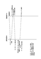
- FIG. 4C shows the relationship of reliability propagation between the terms relating to X (D) of “check equation # 1” to “check equation # 6”.
- FIG. 4C shows the relationship of reliability propagation between the terms related to X (D) in “checking formula # 1” to “checking formula # 6”, but the same applies to the terms related to P (D). I can say that.
- the LDPC-CC with the time varying period 6 has been described by taking the case of the coding rate 1/2 as an example, but the coding rate is not limited to 1/2.
- coding rate (n ⁇ 1) / n (n is an integer of 2 or more)
- each of information X 1 (D), X 2 (D),... X n ⁇ 1 (D) If the condition regarding the “remainder” is satisfied in the three coefficient sets, the possibility of obtaining good reception quality is increased.
- equations (7-1) to (7-6) are considered.
- X 1 (D), X 2 (D),... X n-1 (D) is a polynomial expression of data (information) X1, X2,... Xn-1
- P (D) Is a polynomial representation of parity.
- X 1 (D), X 2 (D),... X n-1 (D), P (D) each have three terms. Let the parity check polynomial exist.
- the parity at time i is Pi and the information is X i, 1 , X i, 2 , ..., represented by X i, n-1 .
- X 1 (D), X 2 (D), ⁇ X n-1 (D) is data (information) X 1, X 2, a polynomial representation of ⁇ X n-1
- P (D) is a polynomial expression of parity.
- X 1 (D), X 2 (D),... X n-1 (D), P (D) each have three terms. Let the parity check polynomial exist.
- the time varying period 3g represented by the parity check polynomials of the equations (9-1) to (9-3g), the coding rate In an LDPC-CC of (n ⁇ 1) / n (n is an integer of 2 or more), if the following condition ( ⁇ condition # 2>) is satisfied, the possibility that higher error correction capability can be obtained increases.
- X 1 (D), X 2 (D), ⁇ X n-1 (D) is data (information) X 1, X 2, a polynomial representation of ⁇ X n-1, P (D) is a polynomial expression of parity.
- X 1 (D), X 2 (D),... X n-1 (D), P (D) each have three terms. Let the parity check polynomial exist.
- a # k, p, 1 % 3, a # k, p, 2 % 3, a # k, p, 3 % 3), ..., (A # k, n-1,1 % 3, a # k, n-1,2 % 3, a # k, n-1,3 % 3) is Any one of (0, 1, 2), (0, 2, 1), (1, 0, 2), (1, 2, 0), (2, 0, 1), (2, 1, 0) Become.
- ⁇ Condition # 3> for Expressions (11-1) to (11-3g) has the same relationship as ⁇ Condition # 2> for Expressions (9-1) to (9-3g). Adding the following condition ( ⁇ condition # 4>) in addition to ⁇ condition # 3> to formulas (11-1) to (11-3g) creates an LDPC-CC with higher error correction capability The possibility of being able to do increases.
- X 1 (D), X 2 (D), ⁇ X n-1 (D) is data (information) X 1, X 2, a polynomial representation of ⁇ X n-1, P (D) is a polynomial expression of parity.
- equations (13-1) to (13-3g) there are three terms in each of X 1 (D), X 2 (D),... X n-1 (D), P (D)
- a term of D 0 exists in X 1 (D), X 2 (D),... X n-1 (D), P (D).
- K 1, 2, 3, ..., 3g
- a # 3g-2, n-1,1 % 3, a # 3g-2, n-1,2 % 3) is One of (1, 2) and (2, 1).
- P 1, 2, 3,..., N ⁇ 1
- a # 3g-1,1,1 % 3, a # 3g-1,1,2 % 3 is One of (1, 2) and (2, 1).
- a # 3g-1,2,1 % 3, a # 3g-1,2,2 % 3) is One of (1, 2) and (2, 1).
- ⁇ Condition # 5> for Expressions (13-1) to (13-3g) has the same relationship as ⁇ Condition # 2> for Expressions (9-1) to (9-3g). If the following condition ( ⁇ condition # 6>) is added to the expressions (13-1) to (13-3g) in addition to ⁇ condition # 5>, an LDPC-CC having high error correction capability can be created. The possibility increases.
- P 1, 2, 3, ..., 3g
- the following conditions are satisfied in the order of X 3 (D) in the equations (13-1) to (13-3g).
- P 1, 2, 3, ..., 3g
- K 1, 2, 3,..., N ⁇ 1
- the following conditions are satisfied in the order of X n-1 (D) in the equations (13-1) to (13-3g).
- ⁇ Condition # 6> instead of ⁇ Condition # 6>, ⁇ Condition # 6 ′> is used, that is, even if ⁇ Condition # 6 ′> is added in addition to ⁇ Condition # 5>, a higher error correction is possible. There is a high possibility that an LDPC-CC having the capability can be created.
- P 1, 2, 3, ..., 3g
- the following conditions are satisfied in the order of X 3 (D) in the equations (13-1) to (13-3g).
- P 1, 2, 3, ..., 3g
- K 1, 2, 3,..., N ⁇ 1 Or ⁇ ⁇ ⁇ Or The following conditions are satisfied in the order of X n-1 (D) in the equations (13-1) to (13-3g).
- the LDPC-CC having a time varying period of 3 g and a coding rate (n ⁇ 1) / n (n is an integer of 2 or more) has been described above.
- X (D) is a polynomial expression of data (information) X
- P (D) is a polynomial expression of parity.
- the parity check polynomial is such that three terms exist in each of X (D) and P (D).
- X (D) is a polynomial expression of data (information) X
- P (D) is a polynomial expression of parity.
- the parity check polynomial is such that three terms exist in each of X and P (D).
- the parity at time i is represented by Pi and the information is represented by X i, 1 .
- (A # 3,1,1 % 3, a # 3,1,2 % 3, a # 3,1,3 % 3) is (0,1,2), (0,2,1), ( 1, 0, 2), (1, 2, 0), (2, 0, 1), (2, 1, 0).
- (A # k, 1,1 % 3, a # k, 1,2 % 3, a # k, 1,3 % 3) is (0,1,2), (0,2,1), ( 1, 0, 2), (1, 2, 0), (2, 0, 1), (2, 1, 0).
- (Thus, k 1, 2, 3,..., 3g) And, ⁇ ⁇ ⁇ And, (A # 3g-2,1,1% 3 , a # 3g-2,1,2% 3, a # 3g-2,1,3% 3) is (0,1,2), (0, 2, 1), (1, 0, 2), (1, 2, 0), (2, 0, 1), (2, 1, 0). And, (A # 3g-1,1,1 % 3, a # 3g-1,1,2 % 3, a # 3g-1,1,3 % 3) is (0,1,2), (0, 2, 1), (1, 0, 2), (1, 2, 0), (2, 0, 1), (2, 1, 0).
- (A # 3g, 1,1 % 3, a # 3g, 1,2 % 3, a # 3g, 1,3 % 3) is (0,1,2), (0,2,1), ( 1, 0, 2), (1, 2, 0), (2, 0, 1), (2, 1, 0).
- the combination of the orders of P (D) satisfies the following condition. (B # 1,1 % 3, b # 1,2 % 3), (B # 2,1 % 3, b # 2,2 % 3), (B # 3, 1 % 3, b # 3, 2 % 3), ... (B # k, 1 % 3, b # k, 2 % 3), ...
- ⁇ Condition # 3-1> for Expressions (17-1) to (17-3g) has the same relationship as ⁇ Condition # 2-1> for Expressions (15-1) to (15-3g). If the following condition ( ⁇ condition # 4-1>) is added to the expressions (17-1) to (17-3g) in addition to ⁇ condition # 3-1>, LDPC having higher error correction capability -Increased possibility of creating CC.
- X (D) is a polynomial expression of data (information) X
- P (D) is a polynomial expression of parity.
- the parity check polynomial is such that three terms exist in each of X (D) and P (D), and X (D) and P (D) Will have a term of D 0 .
- K 1, 2, 3, ..., 3g
- (Thus, k 1, 2, 3,..., 3g) And, ⁇ ⁇ ⁇ And, (A # 3g-2,1,1% 3 , a # 3g-2,1,2% 3) is a one of the (1,2), (2,1). And, (A # 3g-1,1,1 % 3, a # 3g-1,1,2 % 3) is either (1,2) or (2,1). And, (A # 3g, 1,1 % 3, a # 3g, 1,2 % 3) is either (1,2) or (2,1).
- ⁇ Condition # 5-1> for Expressions (19-1) to (19-3g) has the same relationship as ⁇ Condition # 2-1> for Expressions (15-1) to (15-3g).
- ⁇ Condition # 6-1> When the following condition ( ⁇ condition # 6-1>) is added to the expressions (19-1) to (19-3g) in addition to ⁇ condition # 5-1>, LDPC having higher error correction capability -Increased possibility of creating CC.
- the parity check matrix if there is a regularity at the position where “1” exists, there is a high possibility that a good error correction capability can be obtained.
- the parity check matrix is given randomness while having regularity at the position where “1” exists. Therefore, the possibility that a better error correction capability can be obtained increases.
- ⁇ Condition # 6-1> instead of ⁇ Condition # 6-1>, ⁇ Condition # 6'-1> is used. In other words, ⁇ Condition # 6'-1> is added in addition to ⁇ Condition # 5-1> to create a code. Even so, the possibility that an LDPC-CC having higher error correction capability can be created increases.
- Table 4 lists LDPC-CC having a good error correction capability and a coding rate of 1/2 and a time varying period of 6.
- LDPC-CC having a time varying period g with good characteristics has been described above.
- the generation matrix G is obtained corresponding to a parity check matrix H designed in advance.
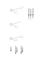
- FIG. 5 describes information related to the (7, 5) convolutional code.
- the data at the time point i is represented as X i
- the parity is represented as P i
- the transmission sequence W i (X i , P i ).
- a transmission vector w (X 1 , P 1 , X 2 , P 2 ,..., X i , P i ...) T is expressed.
- the parity check matrix H can be expressed as shown in FIG. At this time, the following relational expression (23) is established.
- the parity check matrix H is used, and BP (Belief Propagation) (reliability propagation) decoding as shown in Non-Patent Document 5 to Non-Patent Document 7 and min-sum decoding approximating BP decoding.
- BP Belief Propagation
- Offset BP decoding Normalized BP decoding, shuffled BP decoding, and other decoding using reliability propagation can be performed.
- time-invariant / time-varying LDPC-CC based on convolutional code (coding rate (n-1) / n) (n: natural number))
- coding rate (n-1) / n) (n: natural number)
- the code defined by the parity check matrix based on the parity check polynomial of Equation (24) is referred to herein as time invariant LDPC-CC.
- the information X 1, j , X 2, j ,..., X n ⁇ 1, j and the parity P j at the time point j satisfy the parity check polynomial of Expression (26).
- “j mod m” is a remainder obtained by dividing j by m.
- a code defined by a parity check matrix based on the parity check polynomial of Equation (26) is referred to herein as time-varying LDPC-CC.
- the time-invariant LDPC-CC defined by the parity check polynomial of Equation (24) and the time-varying LDPC-CC defined by the parity check polynomial of Equation (26) sequentially register and exclude parity. It can be easily obtained by logical OR.
- FIG. 6 shows the configuration of an LDPC-CC parity check matrix H with a coding rate of 2/3 and a time-varying period of 2 based on Equations (24) to (26).
- the two check polynomials having different time-varying periods 2 based on the formula (26) are named “check formula # 1” and “check formula # 2”.
- (Ha, 111) is a portion corresponding to “checking formula # 1”
- (Hc, 111) is a portion corresponding to “checking formula # 2”.
- (Ha, 111) and (Hc, 111) are defined as sub-matrices.
- the LDPC-CC parity check matrix H of the proposed time-varying period 2 is divided into the first sub-matrix representing the parity check polynomial of “check equation # 1” and the parity check polynomial of “check equation # 2”. And a second sub-matrix that represents Specifically, in the parity check matrix H, the first sub-matrix and the second sub-matrix are alternately arranged in the row direction. In the case of a coding rate of 2/3, as shown in FIG. 6, in the i-th row and the i + 1-th row, the sub-matrix is shifted to the right by 3 columns.
- the i-th row sub-matrix and the i + 1-th row sub-matrix are different sub-matrices. That is, one of the sub-matrices (Ha, 111) or (Hc, 111) is the first sub-matrix, and the other is the second sub-matrix.
- the parity P mi + 1 at the time point mi + 1 is obtained using the “check equation # 1”
- the parity P mi + 2 at the time point mi + 2 is obtained using the “check equation # 2”
- the parity P mi + m at the time point mi + m is obtained.
- an LDPC-CC obtained using “checking formula #m”.
- Such an LDPC-CC code is The encoder can be easily configured, and the parity can be obtained sequentially. The advantage is that the termination bit can be reduced and the reception quality at the time of puncturing can be improved.
- FIG. 7 shows the configuration of the above parity check matrix of LDPC-CC with a coding rate of 2/3 and a time-varying period m.
- (H 1 , 111) is a portion corresponding to “checking formula # 1”
- (H 2 , 111) is a portion corresponding to “checking formula # 2”
- (H m , 111) is a portion corresponding to “inspection formula #m”.
- (H 1 , 111) is defined as the first sub-matrix
- (H 2 , 111) is defined as the second sub-matrix
- (H m , 111) is defined as the m-th sub-matrix.
- the LDPC-CC parity check matrix H of the proposed time-varying period m is the first sub-matrix representing the parity check polynomial of “check equation # 1” and the parity check polynomial of “check equation # 2”.
- the second sub-matrix can be defined by the m-th sub-matrix representing the parity check polynomial of “check equation #m”.
- the first sub-matrix to the m-th sub-matrix are periodically arranged in the row direction (see FIG. 7). In the case of a coding rate of 2/3, the sub-matrix is shifted to the right by three columns in the i-th row and the i + 1-th row (see FIG. 7).
- the case of the coding rate 2/3 has been described as an example of the time-invariant / time-varying LDPC-CC based on the convolutional code of the coding rate (n ⁇ 1) / n.
- a parity check matrix of time-invariant / time-variant LDPC-CC based on a convolutional code with a coding rate (n ⁇ 1) / n can be created.
- (H 1 , 111) is a portion (first sub-matrix) corresponding to “check equation # 1”, and (H 2 , 111) is “check A part (second sub-matrix) corresponding to “Expression # 2”,..., (H m , 111) is a part (m-th sub-matrix) corresponding to “check expression #m”,
- the number of “1” s excluding H k is n.
- the sub-matrix is shifted to the right by n columns in the i-th row and the i + 1-th row (see FIG. 8).
- the transmit vector u, u (X 1,0, X 2,0, ⁇ , X n-1,0, P 0, X 1,1, X 2,1, ⁇ , X n-1 , 1, P 1, ⁇ , X 1, k, X 2, k, ⁇ , X n-1, k, P k, ⁇ )
- Hu 0 is satisfied ( (Refer Formula (23)).
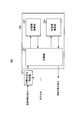
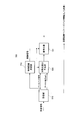
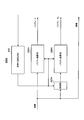
- the LDPC-CC encoder 100 mainly includes a data operation unit 110, a parity operation unit 120, a weight control unit 130, and a mod2 adder (exclusive OR operation) unit 140.
- the data operation unit 110 includes shift registers 111-1 to 111-M and weight multipliers 112-0 to 112-M.
- the parity operation unit 120 includes shift registers 121-1 to 121-M and weight multipliers 122-0 to 122-M.
- the weight multipliers 112-0 to 112-M and 122-0 to 122-M set the values of h 1 (m) and h 2 (m) to 0/1 according to the control signal output from the weight control unit 130. Switch to.
- the weight control unit 130 outputs the values of h 1 (m) and h 2 (m) at the timing based on the parity check matrix held therein, and the weight multipliers 112-0 to 112-M, 122- Supply toward 0-122-M.
- the mod2 adder 140 adds all the mod2 calculation results to the outputs of the weight multipliers 112-0 to 112-M, 122-0 to 122-M, and calculates p i .
- the LDPC-CC encoder 100 can perform LDPC-CC encoding according to a parity check matrix.
- the LDPC-CC encoder 100 is a time-varying convolutional encoder.
- LDPC-CC with a coding rate (q-1) / q (q-1) data operation units 110 are provided, and a mod2 adder 140 adds mod2 outputs (mod2 addition) (Exclusive OR operation) may be performed.
- an LDPC-CC search method capable of supporting a plurality of coding rates with a low computation scale in the encoder / decoder will be described.
- the decoder can achieve high data reception quality.
- the LDPC-CC search method in the present embodiment is based on, for example, LDPC-CC with a coding rate of 1/2 among LDPC-CCs having good characteristics as described above, and coding rate 2/3, Search sequentially for LDPC-CC of 3/4, 4/5,..., (Q ⁇ 1) / q.
- LDPC-CC coding rate of 1/2 among LDPC-CCs having good characteristics as described above, and coding rate 2/3
- an LDPC-CC with a time varying period of 3 is used as an example.
- the LDPC-CC with the time-varying period 3 has a very good error correction capability.
- LDPC-CC search method (1) Coding rate 1/2 First, an LDPC-CC with a coding rate of 1/2 is selected as a base LDPC-CC. As the base LDPC-CC with a coding rate of 1/2, an LDPC-CC with good characteristics as described above is selected.
- an LDPC-CC parity check polynomial with a coding rate of 2/3 is created based on a parity check polynomial with a coding rate of 1/2 with good characteristics.
- an LDPC-CC parity check polynomial with a coding rate of 2/3 includes a parity check polynomial with a basic coding rate of 1/2.
- a parity check polynomial of an LDPC-CC with a coding rate of 2/3 when the equations (27-1) to (27-3) are used for the base LDPC-CC with a coding rate of 1/2 is expressed by the equation (28-). It can be expressed as 1) to formula (28-3).
- the parity check polynomials shown in the equations (28-1) to (28-3) adopt a configuration in which the term X 2 (D) is added to the equations (27-1) to (27-3), respectively.
- the parity check polynomial of the coding rate 2/3 LDPC-CC using the equations (28-1) to (28-3) is the basis of the parity checking polynomial of the coding rate 3/4 described later.
- the information X 1 and X 2 at the time point j are expressed as X 1, j and X 2, j, and the parity P at the time point j is set as P j
- u j (X 1, j , X 2, j , Pj) T.
- an LDPC-CC parity check polynomial with a coding rate of 3/4 is created based on the parity check polynomial with a coding rate of 2/3.
- an LDPC-CC parity check polynomial with a coding rate of 3/4 includes a parity check polynomial with a basic coding rate of 2/3.
- a parity check polynomial of an LDPC-CC with a coding rate of 3/4 when the equations (28-1) to (28-3) are used for the base LDPC-CC with a coding rate of 2/3 is given by the equation (29- 1) to formula (29-3).
- the parity check polynomials shown in Expressions (29-1) to (29-3) employ a configuration in which the term X 3 (D) is added to Expressions (28-1) to (28-3), respectively. .
- each order of X 3 (D), ( ⁇ 1, ⁇ 1), ( ⁇ 2, ⁇ 2), ( ⁇ 3, ⁇ 3) is LDPC with good characteristics.
- LDPC-CC with good characteristics can be obtained even at a coding rate of 3/4 .
- the information X 1, X 2, X 3 at the time point j is expressed as X 1, j, X 2, j, X 3, j .
- the relationship between the check polynomial and the parity check matrix is the same as that described in the above (LDPC-CC having good characteristics).
- Formulas (30-1) to (30- (q-1)) show general formulas of the parity check polynomial of the LDPC-CC having the time-varying period g when searching as described above.
- Expression (30-1) is expressed by a general expression, it is expressed as the expression (30-1), but as described above (LDPC-CC having good characteristics).
- Expression (30-1) is expressed by g parity check polynomials. (As described in the present embodiment, for example, in the case of time varying period 3, it is expressed by three parity check polynomials as in equations (27-1) to (27-3).)
- the equations (30-2) to (30- (q-1)) are also expressed by g parity check polynomials because the time-varying period is g.
- Equation (30-1) g parity check polynomials of Equation (30-1) are represented by Equation (30-1-0), Equation (30-1-1), Equation (30-1-2),. 30-1- (g-2)) and the expression (30-1- (g-1)).
- g parity check polynomials of the equation (30-w) are expressed by the equation (30-w-0), the equation (30-w-1), the equation (30-w-2),. 30-w- (g-2)) and expression (30-w- (g-1)).
- X 1, i , X 2, i ,..., X q ⁇ 1, i are information X 1 , X 2 ,..., X q ⁇ 1
- P i indicates the parity P at time i.
- Equation (30-1) is an LDPC-CC parity check polynomial of time varying period g corresponding to coding rate 1/2
- Equation (30-2) corresponds to coding rate 2/3
- Equation (30- (q-1)) is LDPC- of time-varying period g corresponding to coding rate (q-1) / q. It is a parity check polynomial of CC.
- Equation (30-1) which is an LDPC-CC parity check polynomial with good coding rate 1/2
- Equation (302) a parity check polynomial of LDPC-CC with coding rate 2/3 ( 30-2) is generated.
- an LDPC-CC parity check polynomial (30-3) with a coding rate of 3/4 is generated based on an LDPC-CC parity check polynomial (30-2) with a coding rate of 2/3.
- Another expression is used for the above parity check polynomial construction method.
- the maximum coding rate is (q ⁇ 1) / q among the coding rates for the common use of the encoder circuit and the common use of the decoder circuit, and g is 2 or more.
- An integer, y is an integer of 2 or more, z is an integer of 2 or more, and a relationship of y ⁇ z ⁇ q is established.
- the sharing of the circuit of the encoder is the sharing of the circuit inside the encoder, not the sharing of the circuit of the encoder and the decoder.
- an LDPC-CC encoder with a time varying period g at a coding rate (y ⁇ 1) / y and a time varying period g at a coding rate (z ⁇ 1) / z
- An LDPC-CC encoder can share a circuit, and an LDPC-CC decoder having a time-varying period g at a coding rate (y-1) / y, and a coding rate (z- 1)
- An LDPC-CC decoder having a time-varying period g at / z can share a circuit.
- the conditions are as follows.
- B 0 and (D) is of formula (31-1) B 0 of (D) and Formula (32-1), equality is established.”
- An LDPC-CC encoder can share a circuit, and an LDPC-CC decoder and a coding rate (z-1) with a time-varying period g at a coding rate (y-1) / y.
- the circuit can be shared with an LDPC-CC decoder having a time-varying period g at) / z.
- the method for sharing the encoder circuit and the method for sharing the decoder circuit will be described in detail later (configuration of the encoder and decoder).
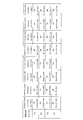
- Table 5 shows an example of an LDPC-CC parity check polynomial satisfying the above-mentioned conditions and having a time-varying period of 3 and corresponding coding rates of 1/2, 2/3, 3/4, and 5/6.
- the format of the parity check polynomial is represented in the same format as that in Table 3.
- a X1,0 (D) in the equation (31-1) becomes D 373 + D 56 +1, and the coding rate in Table 5 is obtained.
- a X1,0 (D) in equation (32-1) becomes D 373 + D 56 +1
- a X1,0 (D) in the equation (32-1) is an equal sign.
- B 0 (D) in Equation (31-1) becomes D 406 + D 218 +1
- a X1,2 (D) in Expression (31-3) becomes D 485 + D 70 +1, and the coding in Table 5 is performed.
- a X1,2 (D) in the equation (32-3) D 485 + D 70 +1, and “A X1,2 in the equation (31-3) ( D) and A X1,2 (D) in equation (32-3) are equal.
- B 2 (D) in the equation (31-3) becomes D 236 + D 181 +1
- the coding rate 2 / 3 B 2 (D) in the equation (32-3) becomes D 236 + D 181 +1
- the LDPC-CC with the time-varying period 3 at the coding rate 1/2 in Table 5 and the LDPC-CC with the time-varying period 3 in the coding rate 2/3 in Table 5 are the above conditions. Can be confirmed.
- the time varying period 3 of two different coding rates out of the coding rates 1/2, 2/3, 3/4, and 5/6. If the LDPC-CC is selected and verification is made as to whether the above condition is satisfied, it can be confirmed that the above condition is satisfied in any selection pattern.
- LDPC-CC is a kind of convolutional code
- termination and tail biting are required to ensure reliability in decoding of information bits.
- Information-zero-termination a method of setting the state of data (information) X to zero (hereinafter referred to as “Information-zero-termination”) is considered.
- Figure 10 shows the “Information-zero-termination” method.
- the information bit (final transmission bit) to be transmitted last in the information sequence to be transmitted is Xn (110).
- the transmission apparatus transmits data only up to the parity bit generated by the encoder in accordance with the final information bit Xn (110)
- the reception apparatus performs decoding, the reception quality of information is greatly deteriorated.
- encoding is performed assuming that the information bits after the last information bit Xn (110) (referred to as “virtual information bits”) are “0”, and a parity bit (130) is generated. To do.
- parity bits (120) generated by virtual information bits (120) while ensuring data reception quality. 130) should be as small as possible.
- LDPC-CC when the time varying period m (m is an integer and m ⁇ 2) and the coding rate is 1/2 will be described as an example.
- the time-varying period is m
- B i (D) D 18 + D 4 + D 0
- the orders that exist for D are all composed of orders of 0 or more, such as 18, 4 , 0).
- the highest order of D in B 1 (D) is ⁇ 1
- the highest order of D in B 2 (D) is ⁇ 2
- the highest order of ⁇ i (D) is the highest order of D in ⁇ m ⁇ 1 .
- ⁇ is 1/2 or less of ⁇ .
- LDPC-CC when the time-varying period m (m is an integer and m ⁇ 2) and the coding rate is 4/5 will be described as an example.
- the required m parity check polynomials are expressed by the following equations.
- i 0, 1,..., M ⁇ 1.
- a X1,2 (D) has the highest order of D as ⁇ 1,2 ,.
- the highest order of D in A X1, i (D) is ⁇ 1, i ,...,
- the highest order of D in A X1, m-1 (D) is ⁇ 1, m-1 .
- the highest order of D in B 1 (D) is ⁇ 1
- the highest order of D in B 2 (D) is ⁇ 2
- B i (D) is the highest in D the degree ⁇ i, ⁇
- the highest order of D in B m-1 (D) and beta m-1 is ⁇ .
- ⁇ is 1/2 or less of ⁇ 1 and ⁇ is ⁇ 2 . It is good to say that it is 1/2 or less, ⁇ is 1/2 or less of ⁇ 3 , and ⁇ is 1/2 or less of ⁇ 4 .
- ⁇ is 1/2 or less of ⁇ 1 or ⁇ is 1/2 or less of ⁇ 2 or ⁇ is 1/2 or less of ⁇ 3 or ⁇ is 1/2 or less of ⁇ 4 ”
- the number of parity bits generated by the virtual information bits can be reduced as much as possible, but there is a possibility that the data reception quality will be slightly reduced (however, However, this does not necessarily lead to a decrease in data reception quality.)
- the required m parity check polynomials are expressed by the following equations.
- i 0, 1,..., M ⁇ 1.
- a X1,2 (D) has the highest order of D as ⁇ 1,2 ,.
- the highest order of D in A X1, i (D) is ⁇ 1, i ,...,
- the highest order of D in A X1, m-1 (D) is ⁇ 1, m-1 .
- the highest order of D in B 1 (D) is ⁇ 1
- the highest order of D in B 2 (D) is ⁇ 2
- B i (D) is the highest in D the degree ⁇ i, ⁇
- the highest order of D in B m-1 (D) and beta m-1 is ⁇ .
- ⁇ is 1 ⁇ 2 or less of ⁇ 1
- ⁇ is 1 ⁇ 2 or less of ⁇ 2
- ⁇ is 1 ⁇ 2 or less of ⁇ u
- Is 1/2 or less of ⁇ n ⁇ 1 (u 1, 2, 3,..., N ⁇ 2, n ⁇ 1) ”
- u 1, 2, 3,..., N ⁇ 2, n ⁇ 1
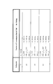
- Table 6 shows LDPC-CCs with a time-varying period of 3, a coding rate of 1/2, 2/3, 3/4, and 4/5 that can reduce the number of redundant bits while ensuring data reception quality.
- An example of a parity check polynomial is shown.
- the LDPC-CC with time varying period 3 in Table 6 the LDPC-CC with time varying period 3 of two different coding rates out of the coding rates 1/2, 2/3, 3/4, and 4/5.
- the number of redundant bits (redundant bits added for “Information-zero-termination”) required for the code of coding rate (n ⁇ 1) / n is the coding rate (m ⁇ 1) / m. It tends to be more than the number of redundant bits required for a code (redundant bits added for “Information-zero-termination”), and the redundancy required for a code of coding rate (n ⁇ 1) / n When the information size is small, the number of bits tends to be larger than the number of redundant bits necessary for a code of coding rate (m ⁇ 1) / m. However, this is not necessarily the case.
- the maximum coding rate is (q ⁇ 1) / q among the coding rates for the common use of the encoder circuit and the common use of the decoder circuit, and the coding rate (r ⁇ 1)
- At least an LDPC-CC encoder with a time-varying period g of a coding rate (y-1) / y and an LDPC-CC encoder with a time-varying period g of a coding rate (z-1) / z are provided.
- the reception apparatus including the decoder, the method of generating the parity check polynomial of the LDPC-CC having the time-varying period g capable of reducing the operation scale (circuit scale), and the characteristics of the parity check polynomial have been described.
- the transmission apparatus transmits a modulation signal for transmitting an LDPC-CC encoded sequence having at least a coding rate (y ⁇ 1) / y with a time varying period g, or a coding rate (z ⁇ 1) / y
- a modulation signal for transmitting an LDPC-CC encoded sequence having at least a coding rate (y ⁇ 1) / y with a time varying period g, or a coding rate (z ⁇ 1) / y
- the receiving apparatus receives at least a received signal including an LDPC-CC encoded sequence having a time-varying period g of encoding rate (y-1) / y, or encoding rate (z-1) / z.
- This is a receiving apparatus that demodulates and decodes any received signal including an LDPC-CC encoded sequence of variable period g.
- the LDPC-CC having the time-varying period g proposed in the present invention, it is possible to reduce the operation scale (circuit scale) between the transmission apparatus including the encoder and the reception apparatus including the decoder (The circuit can be shared).
- the receiving apparatus can obtain high data reception quality at any coding rate.
- the configuration of the encoder, the configuration of the decoder, and the operation thereof will be described in detail below.
- the coding rate is 1/2, 2/3, 3/4,..., (Q-1) / q.
- the transmission apparatus including the encoder and the reception apparatus including the decoder have the coding rates 1/2, 2/3, 3/4,. It is not necessary to support all of (q-1) / q, and if at least two different coding rates are supported, the operation scale (circuit scale) of the transmission apparatus and the reception apparatus is reduced (encoding And a common circuit of the decoder and the decoder) and an effect that the receiving apparatus can obtain high data reception quality.
- the description is based on the code of (LDPC-CC having good characteristics) described in Embodiment 1, but it is not necessarily described by the above (LDPC-CC having good characteristics).
- the present embodiment is similarly implemented if the LDPC-CC has a time-varying period g based on the parity check polynomial of the format described in (LDPC-CC having good characteristics) described above. (G is an integer of 2 or more). This is clear from the relationship between (31-1) to (31-g) and (32-1) to (32-g).
- the transmission / reception apparatus supports coding rates 1/2, 2/3, 3/4, 5/6, and coding rates 1/2
- 2/3, 3/4 use LDPC-CC based on the above rule
- a coding rate of 5/6 uses a code not based on the above rule
- an encoder / decoder The circuit can be shared for coding rates 1/2, 2/3, and 3/4, and the circuit sharing is difficult for coding rates 5/6.
- the highest coding rate among the coding rates for sharing the encoder circuit and sharing the decoder circuit is (q ⁇ 1) / q (for example, When the encoding rate corresponding to the transmission / reception apparatus is 1/2, 2/3, 3/4, 5/6, the codes of the encoding rates 1/2, 2/3, and 3/4 are encoded by the encoder / In the decoder, the circuit is shared, and the coding rate of 5/6 is not to be shared by the encoder / decoder, and the highest coding rate (q ⁇ 1) / q is 3/4.), LDPC with a time-varying period g (g is a natural number) that can correspond to a plurality of coding rates (r-1) / r (r is an integer of 2 to q) -Describes the encoder that creates the CC.
- g is a natural number
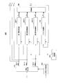
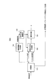
- FIG. 11 is a block diagram showing an example of a main configuration of the encoder according to the present embodiment.
- the encoder 200 shown in FIG. 11 is an encoder that can handle coding rates of 1/2, 2/3, and 3/4.
- 11 includes an information generating unit 210, a first information calculating unit 220-1, a second information calculating unit 220-2, a third information calculating unit 220-3, a parity calculating unit 230, an adding unit 240, It mainly includes a coding rate setting unit 250 and a weight control unit 260.
- the information generation unit 210 sets the information X 1, i , the information X 2, i , and the information X 3, i at the time point i according to the coding rate specified by the coding rate setting unit 250. For example, when the coding rate setting unit 250 sets the coding rate to 1 ⁇ 2, the information generation unit 210 sets the input information data S j to the information X 1, i at the time point i, and the information X at the time point i. 2, the information of i and time i X 3, i is set to 0.
- the information generation unit 210 sets the input information data S j to the information X 1, i at the time point i, and the input information data S j + 1 to the information X 2, i at the time point i. Set, and set the information X 3, i at time i to 0.
- the information generation unit 210 sets the input information data S j to the information X 1, i at the time point i, and the input information data S j + 1 to the information X 2, i at the time point i. Then, the input information data S j + 2 is set to the information X 3, i at the time point i.
- the information generating unit 210 according to the coding rate coding rate set by the setting unit 250, information X 1 of point in time i to input information data, i, information X 2, i, information X 3 , I are set, the set information X 1, i is output to the first information calculation unit 220-1, and the set information X 2, i is output to the second information calculation unit 220-2. Then, the set information X 3, i is output to the third information calculation unit 220-3.
- the first information calculation unit 220-1 calculates X 1 (D) according to A X1, k (D) in Expression (30-1).
- the second information calculation unit 220-2 calculates X 2 (D) according to A X2, k (D) in Expression (30-2).
- the third information calculation unit 220-3 calculates X 3 (D) according to A X3, k (D) in Expression (30-3).
- the above operation is performed on the basis of the configuration of the encoder with the highest coding rate among the coding rates that can be shared by the encoder circuit. It is possible to cope with other coding rates. That is, the first information calculation unit 220-1, the second information calculation unit 220-2, and the third information calculation unit 220-3, which are main parts of the encoder, are shared regardless of the coding rate.
- the LDPC-CC described in Embodiment 2 has the advantage that it can be used.
- the LDPC-CC shown in Table 5 has the advantage of providing good data reception quality regardless of the coding rate.
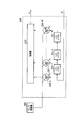
- FIG. 12 shows the internal configuration of the first information calculation unit 220-1. 12 includes shift registers 221-1 to 221-M, weight multipliers 222-0 to 222-M, and an adder 223.
- Weight multipliers 222-0 to 222 -M switch the value of h 1 (m) to 0 or 1 according to the control signal output from weight control section 260.
- the adder 223 performs an exclusive OR operation on the outputs of the weight multipliers 222-0 to 222-M, calculates the operation result Y 1, i, and calculates the calculated Y 1, i in FIG. Output to the adder 240.
- the internal configuration of the second information calculation unit 220-2 and the third information calculation unit 220-3 is the same as that of the first information calculation unit 220-1, and thus the description thereof is omitted. Similar to the first information calculation unit 220-1, the second information calculation unit 220-2 calculates the calculation result Y 2, i and outputs the calculated Y 2, i to the addition unit 240. The third information calculation unit 220-3 calculates the calculation result Y 3, i in the same manner as the first information calculation unit 220-1, and sends the calculated Y 3, i to the addition unit 240 in FIG. Output.
- the parity calculation unit 230 in FIG. 11 calculates P (D) according to B k (D) in Expressions (30-1) to (30-3).
- FIG. 13 shows an internal configuration of the parity calculation unit 230 of FIG. 13 includes shift registers 231-1 to 231-M, weight multipliers 232-0 to 232-M, and an adder 233.
- Weight multipliers 232-0 to 232-M switch the value of h 2 (m) to 0 or 1 according to the control signal output from weight control section 260.
- the adder 233 performs an exclusive OR operation on the outputs of the weight multipliers 232-0 to 232-M, calculates an operation result Z i, and outputs the calculated Z i to the adder 240 in FIG. Output.
- the adder 240 calculates the computations output from the first information computation unit 220-1, the second information computation unit 220-2, the third information computation unit 220-3, and the parity computation unit 230.
- the result Y 1, i , Y 2, i , Y 3, i , Z i is subjected to an exclusive OR operation to obtain and output a parity P i at time i.
- the adder 240 also outputs the parity P i at time i to the parity calculator 230.
- the coding rate setting unit 250 sets the coding rate of the encoder 200, and outputs the coding rate information to the information generation unit 210.
- the weight control unit 260 uses the equations (30-1) to (30-3) based on the parity check matrix corresponding to the equations (30-1) to (30-3) held in the weight control unit 260.
- the value of h 1 (m) at time i based on the parity check polynomial is stored in the first information calculation unit 220-1, the second information calculation unit 220-2, the third information calculation unit 220-3, and the parity calculation unit 230. Output toward.
- the weight control unit 260 determines the value of h 2 (m) at the timing based on the parity check matrix corresponding to the equations (30-1) to (30-3) held in the weight control unit 260. Output to 232-0 to 232-M.
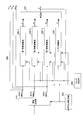
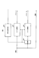
- FIG. 14 shows another configuration example of the encoder according to the present embodiment.
- the same reference numerals as those in FIG. 11 are given to the components common to the encoder of FIG.
- the coding rate setting unit 250 converts the coding rate information into the first information calculation unit 220-1, the second information calculation unit 220-2, the third information calculation unit 220-3, And it is different from the encoder 200 of FIG. 11 in that it is output toward the parity calculation unit 230.
- the second information calculation unit 220-2 When the coding rate is 1/2, the second information calculation unit 220-2 outputs 0 to the addition unit 240 as the calculation result Y2 , i without performing the calculation process. In addition, when the coding rate is 1/2 or 2/3, the third information calculation unit 220-3 does not perform the calculation process and directs 0 as the calculation result Y 3, i to the addition unit 240. Output.
- the information generation unit 210 sets the information X 2, i and the information X 3, i at the time point i to 0 according to the coding rate, whereas FIG.
- the second information calculation unit 220-2 and the third information calculation unit 220-3 stop the calculation process according to the coding rate, and calculate the calculation results Y 2, i , Y 3, i. Since 0 is output, the obtained calculation result is the same as that of the encoder 200 of FIG.
- the second information calculation unit 220-2 and the third information calculation unit 220-3 stop the calculation process according to the coding rate. Computational processing can be reduced compared to the generator 200.
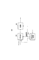
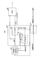
- FIG. 15 is a block diagram showing a main configuration of the decoder according to the present embodiment.
- the decoder 300 shown in FIG. 15 is a decoder that can handle coding rates of 1/2, 2/3, and 3/4.
- the decoder 300 of FIG. 14 mainly includes a log likelihood ratio setting unit 310 and a matrix processing calculation unit 320.
- Log-likelihood ratio setting section 310 receives a received log-likelihood ratio and a coding rate calculated by a log-likelihood ratio calculation section (not shown), and is known to the received log-likelihood ratio according to the coding rate. Insert log-likelihood ratio.
- the log likelihood ratio setting unit 310 receives the received log likelihood ratios LLR X1, i , LLR Pi corresponding to X 1, i and P i as inputs. To do. Accordingly, the log likelihood ratio setting unit 310 inserts the received log likelihood ratios LLR X2, i , LLR 3, i corresponding to X 2, i , X 3, i .
- the reception log likelihood ratio surrounded by a dotted circle indicates the reception log likelihood ratio LLR X2, i , LLR 3, i inserted by the log likelihood ratio setting unit 310.
- Log likelihood ratio setting section 310 inserts a log likelihood ratio of a fixed value as reception log likelihood ratio LLR X2, i , LLR 3, i .
- the log likelihood ratio setting unit 310 determines the known bit “0”. Is inserted as a log likelihood ratio of X 3, i , and the log likelihood ratio after the insertion is output to the matrix processing operation unit 320.
- log likelihood ratio setting section 310 inserts received log likelihood ratio LLR 3, i corresponding to X 3, i .
- the reception log likelihood ratio surrounded by a dotted circle represents the reception log likelihood ratio LLR 3, i inserted by the log likelihood ratio setting unit 310.
- Log-likelihood ratio setting section 310 inserts a log-likelihood ratio of a fixed value as reception log-likelihood ratio LLR 3, i .
- 15 includes a storage unit 321, a row processing calculation unit 322, and a column processing calculation unit 323.
- the storage unit 321 holds the reception log likelihood ratio, the external value ⁇ mn obtained by row processing, and the prior value ⁇ mn obtained by column processing.
- the row processing calculation unit 322 holds a weight pattern in the row direction of the parity check matrix H of the LDPC-CC having the maximum coding rate 3/4 among the coding rates supported by the encoder 200.
- the row processing calculation unit 322 reads the necessary prior value ⁇ mn from the storage unit 321 according to the weight pattern in the row direction, and performs row processing calculation.
- row processing computation section 322 using a priori value beta mn, it performs decoding of a single parity check codes, obtains external value alpha mn.
- the column processing calculation unit 323 holds a weight pattern in the column direction of the parity check matrix H of the LDPC-CC having the maximum coding rate 3/4 among the coding rates supported by the encoder 200.
- the column processing calculation unit 323 reads the necessary external value ⁇ mn from the storage unit 321 according to the weight pattern in the column direction, and obtains the prior value ⁇ mn .
- the column processing calculation unit 323 obtains the prior value ⁇ mn by iterative decoding using the input log likelihood ratio ⁇ n and the external value ⁇ mn .
- the decoder 300 obtains a posterior log likelihood ratio by repeating the above-described row processing and column processing a predetermined number of times.
- the highest coding rate among the available coding rates is set to (q ⁇ 1) / q, and the coding rate setting unit 250 sets the coding rate to (s ⁇ 1)
- the information generation unit 210 sets information from the information X s, i to the information X q-1, i to zero.
- the first information calculation unit 220-1 inputs the information X1 , i at the time point i, and the expression
- the X 1 (D) term of (30-1) is calculated.
- the second information calculation unit 220-2 inputs the information X2 , i at the time point i, and calculates the X 2 (D) term of the equation (30-2).
- the third information computing section 220-3 receives the information X 3, i at the time i, and calculates the X 3 (D) term of formula (30-3).
- the parity calculation unit 230 receives the parity P i ⁇ 1 at the time point i ⁇ 1, and calculates the P (D) term in the equations (30-1) to (30-3).
- the adding unit 240 performs exclusive OR of the calculation results of the first information calculation unit 220-1, the second information calculation unit 220-2, and the third information calculation unit 220-3 and the calculation result of the parity calculation unit 230. , The parity P i at time i is obtained.
- the configuration of the information calculation unit in this description can be shared, so that a plurality of coding rates can be achieved with a low calculation scale.
- LDPC-CC encoders and decoders that are compatible with the above can be provided.
- a X1, k (D) to A Xq-1, k (D) satisfy ⁇ Condition # 1> to ⁇ Condition # 6> and the like described in the above “LDPC-CC having good characteristics”.
- an encoder and a decoder that can handle different coding rates can be provided on a low computation scale, and the receiver can obtain good data reception quality.
- the LDPC-CC generation method is not limited to the above-described “LDPC-CC having good characteristics”.
- the decoder 300 in FIG. 15 includes a log-likelihood ratio setting unit in a decoder configuration corresponding to the maximum coding rate among coding rates that enable sharing of the decoder circuit. By adding 310, decoding can be performed corresponding to a plurality of coding rates.
- the log-likelihood ratio setting unit 310 performs log-likelihood corresponding to (q ⁇ 2) pieces of information from the information X r, i at the time point i to the information X q ⁇ 1, i according to the coding rate. Set the ratio to the default value.
- the maximum coding rate supported by the encoder 200 is 3/4 has been described.
- the maximum coding rate supported is not limited to this, and the coding rate (q ⁇ 1 ) / Q (q is an integer equal to or greater than 5), and is applicable (naturally, the maximum coding rate may be 2/3).
- the encoder 200 is configured to include first to (q ⁇ 1) th information calculation units, and the addition unit 240 includes the calculation results and parity of the first to (q ⁇ 1) th information calculation units.
- the exclusive oR operation result of the arithmetic unit 230 may be so obtained as parity P i at time i.
- sum-product decoding has been described as an example of the decoding method.
- the decoding method is not limited to this, and is described in Non-Patent Document 5 to Non-Patent Document 7, for example, min It can be similarly implemented by using a decoding method (BP decoding) using a message-passing algorithm such as -sum decoding, Normalized BP (Belief Propagation) decoding, Shuffled BP decoding, and Offset BP decoding.
- BP decoding BP decoding
- a message-passing algorithm such as -sum decoding, Normalized BP (Belief Propagation) decoding, Shuffled BP decoding, and Offset BP decoding.
- the present invention is applied to a communication device that adaptively switches the coding rate depending on the communication status.
- a case where the present invention is applied to a wireless communication device will be described as an example.
- the present invention is not limited thereto, and is not limited to a power line communication (PLC) device, a visible light communication device, or an optical communication device. Is also applicable.
- PLC power line communication
- FIG. 18 shows a configuration of communication apparatus 400 that adaptively switches the coding rate.
- the coding rate determination unit 410 of the communication device 400 in FIG. 18 receives a reception signal (for example, feedback information transmitted from the communication partner) transmitted from the communication device of the communication partner, and performs reception processing on the received signal. Then, the coding rate determination unit 410 displays information on the communication status with the communication device of the communication partner, for example, information such as a bit error rate, a packet error rate, a frame error rate, and a received electric field strength (for example, feedback information). From the information on the communication status with the communication apparatus of the communication partner, the coding rate and the modulation method are determined. Then, the coding rate determination unit 410 outputs the determined coding rate and modulation scheme to the encoder 200 and the modulation unit 420 as control signals.
- a reception signal for example, feedback information transmitted from the communication partner
- the coding rate determination unit 410 displays information on the communication status with the communication device of the communication partner, for example, information such as
- the coding rate determination unit 410 uses, for example, a transmission format as shown in FIG. 19 to include the coding rate information in the control information symbol, thereby changing the coding rate used by the encoder 200 to the communication partner's communication. Notify the device. However, although not shown in FIG. 19, it is assumed that the communication partner includes, for example, a known signal (preamble, pilot symbol, reference symbol, etc.) necessary for demodulation and channel estimation.
- the coding rate determination unit 410 receives the modulated signal transmitted by the communication partner communication device 500 and determines the coding rate of the modulated signal to be transmitted based on the communication status. Adaptively switch the conversion rate.
- the encoder 200 performs LDPC-CC encoding according to the above-described procedure based on the encoding rate specified by the control signal.
- Modulation section 420 modulates the encoded sequence using the modulation scheme specified by the control signal.
- FIG. 20 shows a configuration example of a communication apparatus of a communication partner that communicates with the communication apparatus 400.
- Control information generating section 530 of communication apparatus 500 in FIG. 20 extracts control information from control information symbols included in the baseband signal.
- the control information symbol includes coding rate information.
- Control information generation section 530 outputs the extracted coding rate information as a control signal to log likelihood ratio generation section 520 and decoder 300.
- Receiving section 510 obtains a baseband signal by performing processing such as frequency conversion and orthogonal demodulation on the received signal corresponding to the modulated signal transmitted from communication apparatus 400, and obtains the baseband signal to log likelihood ratio generation section 520. Output toward.
- the reception unit 510 estimates a channel variation in a (for example, wireless) transmission path between the communication device 400 and the communication device 500 using a known signal included in the baseband signal, and obtains the estimated channel estimation signal. Output to log likelihood ratio generation section 520.
- the reception unit 510 uses a known signal included in the baseband signal to estimate channel fluctuation in a (for example, wireless) transmission path between the communication apparatus 400 and the communication apparatus 500, and determines the state of the propagation path.
- Feedback information (channel fluctuation itself, for example, Channel State Information is an example) is generated and output. This feedback information is transmitted to a communication partner (communication device 400) as part of control information through a transmission device (not shown).
- Log likelihood ratio generation section 520 obtains the log likelihood ratio of each transmission sequence using the baseband signal, and outputs the obtained log likelihood ratio to decoder 300.
- the decoder 300 corresponds to the information from the information X s, i at the time point i to the information X s-1, i according to the coding rate (s ⁇ 1) / s indicated by the control signal.
- the coding rates of the communication device 400 to which the present invention is applied and the communication device 500 of the communication partner can be adaptively changed depending on the communication status.
- the method of changing the coding rate is not limited to this, and the communication apparatus 500 that is the communication partner may include the coding rate determination unit 410 and specify a desired coding rate. Further, the communication apparatus 400 may estimate the fluctuation of the transmission path from the modulated signal transmitted by the communication apparatus 500 and determine the coding rate. In this case, the above feedback information is not necessary.
- Embodiment 4 In the first embodiment, the LDPC-CC having a high error correction capability has been described. In the present embodiment, a supplementary description will be given of an LDPC-CC with a time-varying period 3 having a high error correction capability. In the case of an LDPC-CC with a time-varying period of 3, when a regular LDPC code is generated, a code with high error correction capability can be created.
- # Xk4: (ak, 1% 3, ak, 2% 3) [0,1]
- the LDPC-CC with good characteristics described in the first embodiment is an LDPC-CC that satisfies the conditions of # Xk12 and # P12 among the above conditions. Further, when used together with the second embodiment, the circuit scales of the encoder and decoder can be reduced and high error correction capability can be obtained when dealing with a plurality of coding rates.
- the encoder circuit can be shared and the decoder can be shared.
- the required number of terminations differs depending on the number of bits of data (information) X (hereinafter referred to as “information size”) as shown in FIG.
- the number of terminations is the number of parity bits generated by the virtual known information bit “0” after performing the above-described information-zero-termination, and is the number of redundant bits actually transmitted.
- Real R effective coding rate indicates a coding rate when a termination sequence composed of redundant bits is considered.
- a communication device and a communication method for changing the number of terminations transmitted as redundant bits according to the information size will be described.
- the error correction capability is not deteriorated and a reduction in information transmission efficiency can be avoided.
- FIG. 24 is a block diagram showing the main configuration of communication apparatus 600 according to the present embodiment.
- the coding rate setting unit 610 receives a control information signal including coding rate information set by the device itself or a feedback signal transmitted from the communication device of the communication partner. When the control information signal is input, coding rate setting section 610 sets the coding rate from the coding rate information included in the control information signal.
- the coding rate setting unit 610 when a feedback signal is input, includes information on a communication status with the communication apparatus of the communication partner included in the feedback signal, for example, a bit error rate, a packet error rate, a frame Information capable of estimating communication quality such as an error rate and received electric field strength is acquired, and a coding rate is set from information on a communication state with a communication apparatus as a communication partner.
- the coding rate setting unit 610 includes information on the set coding rate in the set coding rate signal, and the set coding rate signal is directed to the termination sequence length determination unit 631 and the parity calculation unit 632 in the encoder 630. Output. Also, the coding rate setting unit 610 outputs information on the set coding rate to the transmission information generation and information length detection unit 620.
- the transmission information generation and information length detection unit 620 generates or acquires transmission data (information), and outputs an information sequence composed of the transmission data (information) to the parity calculation unit 632.
- the transmission information generation and information length detection unit 620 detects a sequence length of transmission data (information) (hereinafter referred to as “information length”), that is, an information size, and includes information on the detected information size in the information length signal.
- the information length signal is output to the termination sequence length determination unit 631.
- the transmission information generation and information length detection unit 620 includes known information bits (for example, “0”) necessary for generating redundant bits for the termination sequence length notified from the termination sequence length determination unit 631. Is added to the end of the information series.
- the termination sequence length determination unit 631 determines the termination sequence length (the number of terminations) according to the information size indicated by the information length signal and the coding rate indicated by the set coding rate signal. A specific method for determining the termination sequence length will be described later. Termination sequence length determination section 631 includes the determined termination sequence length in the termination sequence length signal, and outputs the termination sequence length signal to transmission information generation and information length detection section 620 and parity calculation section 632.
- the parity calculation unit 632 calculates parity for the information sequence and the known information sequence, and outputs the obtained parity to the modulation unit 640.
- the modulation unit 640 performs modulation processing on the information series and parity (including the termination series).
- the present invention is not limited to this, and any signal can be used as long as the information is an index for controlling the termination sequence length. May be.
- the frame length of the transmission signal is obtained from the information (Length information) of the number of information excluding termination and the number of parity, the information number and the modulation method information, and the frame length can be used instead of the information length signal. Good.
- FIG. 25 shows an example in which the termination sequence length is switched in two stages based on the information size and each coding rate.
- FIG. 25 assumes that the minimum information size is set to 512 bits in the communication apparatus 600. However, the minimum size is not necessarily determined.
- ⁇ is the information length of transmission data (information) that must be transmitted.
- the termination sequence length determination unit 631 sets the termination sequence length to 380 bits, and when 1024 ⁇ ⁇ , the termination sequence length determination unit 631 Set the termination sequence length to 340 bits. In this way, the termination sequence length determination unit 631 sets the termination sequence length based on the information length ⁇ of the transmission data (information), so that the termination sequence length does not deteriorate the error correction capability, and The sequence length is set so as to prevent a decrease in information transmission efficiency.
- the termination sequence length is switched to two stages at each coding rate.
- the present invention is not limited to this.
- the termination sequence length may be switched with. In this way, by switching the termination sequence length (number of terminations) to multiple stages based on the information length (information size), the termination sequence length does not degrade the error correction capability and the information transmission efficiency decreases. It is possible to set a suitable sequence length that can prevent
- the communication device 600 uses the transmission format as shown in FIG. 27, for example, to include the coding rate information in the symbol related to the coding rate, thereby changing the coding rate used by the encoder 630 to the communication device of the communication partner.
- the communication apparatus 600 notifies the information of the information length (information size) to the communication apparatus of the communication partner by including information of the information length (information size) in the symbol related to the information size.
- Communication device 600 also includes information for identifying the modulation method, transmission method, or communication partner in the control information symbol, and notifies the communication device of the communication partner.
- Communication device 600 also includes the information sequence and parity in the data symbol and notifies the communication device of the communication partner.
- FIG. 28 shows a configuration example of a communication apparatus 700 of a communication partner that communicates with the communication apparatus 600.
- the communication device 700 in FIG. 28 includes a control information generation unit 710 and a decoder 720 instead of the control information generation unit 530 and the decoder 300 in the communication device 500 in FIG.
- the control information generation unit 710 extracts coding rate information from symbols relating to the coding rate obtained by demodulating (and decoding) the baseband signal. Further, the control information generation unit 710 extracts information length (information size) information from symbols related to information size obtained by demodulating (and decoding) the baseband signal. Control information generation section 710 also extracts information for identifying the modulation scheme, transmission method, or communication partner from the control information symbols. The control information generation unit 710 outputs a control signal including the extracted coding rate information and information length (information size) information to the log likelihood ratio generation unit 520 and the decoder 720.
- the decoder 720 holds a table of the relationship between the information size and the termination sequence length at each coding rate as shown in FIG. 25 or 26, and this table, coding rate information, and The termination sequence length included in the data symbol is determined from information on the information length (information size). Decoder 720 performs BP decoding based on the coding rate and the determined termination sequence length. Thereby, the communication apparatus 700 can perform decoding with high error correction capability.
- FIG. 29 and 30 are diagrams illustrating an example of the flow of information between the communication device 600 and the communication device 700.
- FIG. 29 differs from FIG. 30 in whether the coding rate is set by communication apparatus 600 or communication apparatus 700. Specifically, FIG. 29 shows the information flow when the communication apparatus 600 determines the coding rate, and FIG. 30 shows the information flow when the communication apparatus 700 determines the coding rate. .
- termination sequence length determination section 631 determines the sequence length of the termination sequence that is added to the tail of the information sequence and transmitted according to the information length (information size) and coding rate.
- the parity calculation unit 632 performs LDPC-CC coding on the information sequence and the known information sequence necessary for generating the termination sequence for the determined termination sequence length, and calculates the parity sequence. I made it. As a result, the error correction capability is not deteriorated and a reduction in information transmission efficiency can be avoided.
- FIG. 31 shows a case where the LDPC-CC parity check polynomial shown in Equation (44-i), Equation (45-i), Equation (46-i), and Equation (47-i) is used, as in FIG.
- the information size is 512 bits, 1024 bits, and 2048 bits
- the effective coding rate (Real R) at the coding rate 3/4 and the effective coding rate at the coding rate 4/5 are obtained. In comparison, there is no significant difference between the two.
- the effective coding rate is 0.5735 at the coding rate 3/4, whereas the effective coding rate is 0.5626 at the coding rate 4/5, and the difference is slight. Is about 0.01.
- the effective coding rate of the coding rate 3/4 is larger than the effective coding rate of the coding rate 4/5, and the size of the effective coding rate is reversed. Therefore, depending on the information size, there are cases where even if the coding rate of 3/4 is used, high error correction capability is obtained and transmission efficiency is not suitable.
- 32A, 32B, 32C and 32D show the bit error rates when the termination sequence having the sequence length shown in FIG. 31 is added to an information sequence having an information size of 512 bits, 1024 bits, 2048 bits and 4096 bits.
- 32A, 32B, 32C, and 32D the horizontal axis represents SNR (Signal-to-Noise power ratio) [dB], the vertical axis represents the BER / BLER characteristic, the solid line represents the bit error rate characteristic, and the broken line Indicates block error rate characteristics.
- TMN indicates the number of terminations (Terminaltion number).
- the BER / BLER characteristic at the coding rate R 3/4 has the coding rate R regardless of the information size. It can be seen that this is superior to the BER / BLER characteristic of 4/5.
- 32A, 32B, 32C, and 32D show that the BER / BLER characteristic with an information size of 512 bits (see FIG. 32A) is markedly superior to the BER / BLER characteristic with other information sizes.
- the coding rate 2/3 BER characteristic is substantially equivalent to the coding rate 1/2 BER / BLER characteristic when the information size is 1024 bits.
- the BER / BLER characteristic with a coding rate of 1/2 may be actually unnecessary.
- the information size is 512 bits, it is possible to adopt a method of not supporting the coding rate 1/2, since the lower the coding rate, the lower the propagation efficiency. .
- FIG. 33 is a correspondence table between information sizes and supported coding rates. As shown in FIG. 33, there is an unsupported coding rate depending on the information size. If the supported coding rate is constant regardless of the information size, the communication apparatus 600 and the communication apparatus 700 can communicate with each other in both cases of FIGS. However, as shown in FIG. 33, in the present embodiment, there is an unsupported coding rate depending on the information size, and therefore it is necessary to adjust the designated coding rate.
- the communication device will be described.
- FIG. 34 is a block diagram showing a main configuration of communication apparatus 600A according to the present embodiment.
- the same components as those in FIG. 24 are denoted by the same reference numerals as those in FIG.
- a communication apparatus 600A in FIG. 34 includes an encoder 630A in place of the encoder 630 in FIG.
- Encoder 630A employs a configuration in which coding rate adjustment section 633 is added to encoder 630.
- the coding rate adjustment unit 633 Based on the information length (information size) included in the information length signal input from the transmission information generation and information length detection unit 620, the coding rate adjustment unit 633 performs setting coding input from the coding rate setting unit 610. The coding rate included in the rate signal is adjusted. Specifically, the coding rate adjustment unit 633 holds a correspondence table between the information size and the support coding rate as illustrated in FIG. 33, and is set based on the control information signal or the feedback signal. The coding rate is adjusted with reference to the correspondence table. For example, when the information length (information size) is 1024 bits and the set coding rate signal indicates the coding rate 4/5, the coding rate adjustment is not supported because the coding rate 4/5 is not supported from the correspondence table.
- the unit 633 sets 3/4 having the largest value among the coding rates smaller than the coding rate 4/5 as the coding rate. As shown in FIG. 31, when the information length (information size) is 1024 bits, Real R at the coding rate of 4/5 is 0.5626, and Real R (0.5735) at the coding rate of 3/4. Further, as shown in FIG. 32B, the BER / BLER characteristic is better at the coding rate of 3/4. Accordingly, when the information length (information size) is 1024, the error correction capability is not deteriorated by using the coding rate 3/4 without using the coding rate 4/5, and the information The transmission efficiency can be prevented from decreasing.
- the first coding rate (3/4) ⁇ the second coding rate (4/5)
- the second coding rate is designated when the rate (0.5735) is the same as the second effective coding rate (0.5626) corresponding to the second coding rate (4/5)
- the code The coding rate adjustment unit 633 adjusts the coding rate to the first coding rate.
- the coding rate 1/2 is not supported from the correspondence table.
- the coding rate adjustment unit 633 sets 2/3 having the smallest value among the coding rates larger than the coding rate 1/2 to the coding rate. As shown in FIG. 32A, since the BER / BLER characteristic at a coding rate of 1/2 is very good, even if the coding rate is 2/3, the error correction capability is not deteriorated and information transmission is performed. The efficiency can be prevented from decreasing.
- the coding rate adjusting unit 633 has a coding rate higher than the first coding rate and has a predetermined channel quality.
- the coding rate is adjusted to the second coding rate that can ensure the above.
- the number of coding rates supported by the communication device 600A is changed based on the information length (information size). For example, in the example shown in FIG. 33, if the information length (information size) is less than 512 bits, the communication device 600A supports only two coding rates, and if the information length (information size) is 512 bits or more and less than 4096 bits. Three coding rates are supported, and when the information length (information size) is 4096 or more, four coding rates are supported. By changing the coding rate to be supported, it is possible to achieve both improvement in error correction capability and improvement in information transmission efficiency.
- coding rate adjustment section 633 changes the number of coding rates supported by communication apparatus 600A according to the information length (information size), and changes the coding rate. Adjusted to one of the supported coding rates. Thereby, it is possible to prevent the error correction capability from being deteriorated and the information transmission efficiency from being lowered.
- the communication device 600A supports a coding rate having a small value among coding rates having the same effective coding rate.
- the communication device 600A supports only a coding rate that can ensure a predetermined line quality, without being included in a coding rate that supports a coding rate with very good BER / BLER characteristics. Thereby, it is possible to avoid a decrease in transmission efficiency while ensuring a predetermined line quality.
- the communication apparatus 600A adjusts the coding rate and sets the termination sequence length. If the coding rate information and the information length (information size) information (or termination sequence length information) are simultaneously transmitted to the communication device 700 of the communication partner, the communication device 700 can correctly decode.
- this embodiment may be used in combination with the fifth embodiment. That is, the number of terminations may be changed according to the coding rate and the information size (Information size).
- FIG. 36 is a block diagram showing a configuration of communication apparatus 700A in this case.
- the communication apparatus 700A in FIG. 36 adopts a configuration in which a coding rate adjustment unit 730 is added to the communication apparatus 700 in FIG.
- the communication device 600A supports coding rates 1/2, 2/3, and 3/4 when the information length (information size) is less than 4096 bits, and the code length is 4097 bits when the information length (information size) is 4097 bits. A case of supporting the conversion ratios 1/2, 2/3, 3/4, and 4/5 will be described.
- the coding rate of the information sequence to be transmitted is determined to be 4/5, and communication device 600A and communication device 700A share this coding rate information. It shall be.
- the information length (information size) is 512 bits, as described above, the coding rate adjustment unit 633 of the communication device 600A adjusts the coding rate to 3/4. If this rule is determined in advance between communication device 600A and communication device 700A, communication device 600A and communication device 700A can communicate correctly.
- the coding rate adjustment unit 730 receives a control signal including coding rate information and information length (information size) information as an information length (information The coding rate is adjusted based on the size. For example, when the information length (information size) is 512 bits and the coding rate is 4/5, the coding rate adjustment unit 730 adjusts the coding rate to 3/4. . Thereby, it is possible to prevent the error correction capability from being deteriorated and the information transmission efficiency from being lowered.
- the coding rate adjustment unit 633 and the coding rate adjustment unit 730 may make the number of terminations constant regardless of the coding rate.
- the coding rate adjustment unit 633 and the coding rate adjustment unit 730 use, for example, another parity check polynomial suitable for a termination number of 340 bits, You may make it respond
- a completely different code may be used. For example, a block code may be used.
- FIG. 37 is a block diagram showing an example of the configuration of the encoder according to the present embodiment.
- the coding rate setting unit 810 outputs the coding rate to the control unit 820, the parity calculation unit 830, and the parity calculation unit 840.
- the control unit 820 performs control so that information is not input to the parity calculation unit 840 when the coding rate setting unit 810 designates coding rates 1/2, 2/3, 3/4, and 4/5. Also, the control unit 820 controls the same information as the information input to the parity calculation unit 830 to be input to the parity calculation unit 840 when the coding rate 1/3 is set.
- the parity calculation unit 830 performs coding based on the corresponding parity check polynomial. , Output parity.
- the parity calculation unit 830 calculates the coding rate 1/2 (formula (44-1), formula (44-2), formula (4)). Encoding based on the LDPC-CC parity check polynomial defined in 44-3) with a time varying period of 3) is performed, and a parity P is output.
- the parity calculation unit 840 is an encoder that calculates parity with a coding rate of 1/2.
- the coding rate setting unit 810 designates coding rates 1/2, 2/3, 3/4, and 4/5, the parity calculation unit 840 does not output parity.
- the parity calculation unit 840 receives the same information as the information input to the parity calculation unit 830 and inputs the coding rate 1/2. Encoding based on the parity check polynomial of the LDPC-CC with time-varying period 3 is performed, and the parity Pa is output.
- the encoder 800 since the encoder 800 outputs information, parity P, and parity Pa, the encoder 800 can support a coding rate of 1/3.
- FIG. 38 is a block diagram showing an example of the configuration of the decoder according to the present embodiment.
- the decoder 900 in FIG. 38 is a decoder corresponding to the encoder 800 in FIG.
- the control unit 910 receives the coding rate information indicating the coding rate and the log-likelihood ratio, and when the coding rate is 1/2, 2/3, 3/4, 4/5, Control is performed so that the log likelihood ratio is not input. In addition, when the coding rate is 1/3, the control unit 910 performs control so that the same log likelihood ratio as the log likelihood ratio input to the BP decoding unit 920 is input to the BP decoding unit 930.
- the BP decoding unit 920 operates at all coding rates. Specifically, when the coding rate is 1/3, the BP decoding unit 920 performs BP decoding using the parity check polynomial of the coding rate 1/2 used in the parity calculation unit 830. When the coding rate is 1/3, the BP decoding unit 920 outputs a log likelihood ratio corresponding to each bit obtained by performing BP decoding to the BP decoding unit 930. On the other hand, when the coding rate is 1/2, 2/3, 3/4, 4/5, the BP decoding unit 920 uses the coding rate 1/2, 2/3, 3 used in the parity calculation unit 830. BP decoding is performed using a parity check polynomial of / 4, 4/5. The BP decoding unit 920 outputs the obtained log likelihood ratio after iterative decoding a predetermined number of times.
- the BP decoding unit 930 operates only when the coding rate is 1/3. Specifically, the BP decoding unit 930 performs BP decoding using the parity check polynomial with a coding rate of 1 ⁇ 2 used in the parity calculation unit 840 and applies each bit obtained by performing BP decoding. The corresponding log likelihood ratio is output to the BP decoding unit 920, and after iterative decoding is performed a predetermined number of times, the obtained log likelihood ratio is output.
- the decoder 900 performs iterative decoding while exchanging log likelihood ratios, performs decoding such as turbo decoding, and performs decoding at a coding rate of 1/3.
- FIG. 39 is a configuration example of the encoder according to the present embodiment.
- the same reference numerals as those in FIG. 39 are identical reference numerals as those in FIG. 39.
- the encoder 800 in FIG. 37 is an encoder in which the parity calculation unit 830 obtains a parity of coding rates 1/2, 2/3, 3/4, and 4/5.
- the parity calculation unit 840 includes a code Whereas the encoder 800A shown in FIG. 39 has both a parity operation unit 830A and a parity operation unit 840A, for example, when the encoding rate is 2/3, the encoder 800A in FIG.
- the LDPC-CC encoding with variable period 3 is performed, and the parity calculation unit 830A and the parity calculation unit 840A are codes defined by different parity check polynomials.
- the control unit 820A performs control so that information is not input to the parity calculation unit 840A when the coding rate setting unit 810 designates the coding rate 2/3. Further, the control unit 820A controls the same information as the information input to the parity calculation unit 830A to be input to the parity calculation unit 840A when the coding rate 1/2 is set.
- the parity calculation unit 830A is an encoder that obtains a parity with an encoding rate of 2/3 defined by, for example, Expression (45-1), Expression (45-2), and Expression (45-3).
- Expression (45-1), Expression (45-2), and Expression (45-3) When the coding rate setting unit 810 designates coding rates 1/2 and 2/3, the parity calculation unit 830A outputs the parity P.
- the parity calculation unit 840A is an encoder that calculates parity with an encoding rate of 2/3 defined by a parity check polynomial different from that of the parity calculation unit 830A. Only when the coding rate setting unit 810 specifies the coding rate 1/2, the parity calculation unit 840A outputs the parity Pa.
- encoder 800A when coding rate 1/2 is designated, encoder 800A outputs parity P and parity Pa for 2 bits of information, so that encoder 800A reduces coding rate 1/2. Can be realized.
- the coding rate of the parity calculation unit 830A and the parity calculation unit 840A is not limited to 2/3, and may be a coding rate of 3/4, 4/5,. It suffices that both the parity calculation unit 830A and the parity calculation unit 840A have the same coding rate.
- the embodiment of the present invention has been described above.
- the invention related to LDPC-CC described in the first to fourth embodiments and the invention related to the relationship between the information size and the termination size described in the fifth and subsequent embodiments are independently established. .
- the present invention is not limited to all the above embodiments, and can be implemented with various modifications.
- the description has been mainly given of the case where it is realized by an encoder and a decoder.
- the present invention is not limited to this, and can also be applied when realized by a power line communication device. is there.
- a program for executing the encoding method and the communication method may be stored in advance in a ROM (Read Only Memory), and the program may be operated by a CPU (Central Processor Unit).
- ROM Read Only Memory
- CPU Central Processor Unit
- a program for executing the encoding method and the decoding method is stored in a computer-readable storage medium, the program stored in the storage medium is recorded in a RAM (Random Access Memory) of the computer, and the computer is stored in the storage medium. You may make it operate
- the present invention is useful not only in wireless communication but also in power line communication (PLC), visible light communication, and optical communication.
- PLC power line communication
- visible light communication visible light communication
- optical communication optical communication
- the encoder, the decoder and the encoding method according to the present invention do not deteriorate the error correction capability even when termination is performed in the encoder and the decoder using LDPC-CC, and the information The reduction in transmission efficiency can be avoided.
Landscapes
- Engineering & Computer Science (AREA)
- Physics & Mathematics (AREA)
- Probability & Statistics with Applications (AREA)
- Theoretical Computer Science (AREA)
- Computer Networks & Wireless Communication (AREA)
- Signal Processing (AREA)
- Mathematical Physics (AREA)
- Quality & Reliability (AREA)
- Error Detection And Correction (AREA)
Priority Applications (14)
| Application Number | Priority Date | Filing Date | Title |
|---|---|---|---|
| BRPI1011469A BRPI1011469B1 (pt) | 2009-03-02 | 2010-02-19 | codificador, decodificador, e método de codificação |
| KR1020117020589A KR101625255B1 (ko) | 2009-03-02 | 2010-02-19 | 부호화기, 복호화기 및 부호화 방법 |
| EP18202486.9A EP3468048B1 (en) | 2009-03-02 | 2010-02-19 | Encoding termination of ldpc convolutional codes (ldpc-cc) |
| KR1020167013372A KR101669398B1 (ko) | 2009-03-02 | 2010-02-19 | 송신 장치, 송신 방법, 수신 장치 및 수신 방법 |
| EP15182349.9A EP2963831B1 (en) | 2009-03-02 | 2010-02-19 | Encoding termination of ldpc convolutional codes (ldpc-cc) |
| CN201080010004.8A CN102342025B (zh) | 2009-03-02 | 2010-02-19 | 编码器、解码器以及编码方法 |
| EP10748451.1A EP2405583B1 (en) | 2009-03-02 | 2010-02-19 | Encoder, decoder, and encoding method |
| KR1020167028934A KR101730308B1 (ko) | 2009-03-02 | 2010-02-19 | 패리티 비트 생성 장치 및 패리티 비트 생성 방법 |
| US13/254,435 US8819528B2 (en) | 2009-03-02 | 2010-02-19 | Encoder, decoder, and encoding method |
| US14/316,626 US9048869B2 (en) | 2009-03-02 | 2014-06-26 | Transmission apparatus including encoder, reception apparatus including decoder, and associated methods |
| US14/698,758 US9602142B2 (en) | 2009-03-02 | 2015-04-28 | Transmission apparatus including encoder, reception apparatus including decoder, and associated methods |
| US15/423,259 US10236918B2 (en) | 2009-03-02 | 2017-02-02 | Transmission apparatus including encoder, reception apparatus including decoder, and associated methods |
| US16/250,698 US10727875B2 (en) | 2009-03-02 | 2019-01-17 | Transmission apparatus including encoder, reception apparatus including decoder, and associated methods |
| US16/900,528 US11206049B2 (en) | 2009-03-02 | 2020-06-12 | Transmission apparatus including encoder, reception apparatus including decoder, and associated methods |
Applications Claiming Priority (2)
| Application Number | Priority Date | Filing Date | Title |
|---|---|---|---|
| JP2009048535A JP4898858B2 (ja) | 2009-03-02 | 2009-03-02 | 符号化器、復号化器及び符号化方法 |
| JP2009-048535 | 2009-03-02 |
Related Child Applications (2)
| Application Number | Title | Priority Date | Filing Date |
|---|---|---|---|
| US13/254,435 A-371-Of-International US8819528B2 (en) | 2009-03-02 | 2010-02-19 | Encoder, decoder, and encoding method |
| US14/316,626 Continuation US9048869B2 (en) | 2009-03-02 | 2014-06-26 | Transmission apparatus including encoder, reception apparatus including decoder, and associated methods |
Publications (1)
| Publication Number | Publication Date |
|---|---|
| WO2010100848A1 true WO2010100848A1 (ja) | 2010-09-10 |
Family
ID=42709419
Family Applications (1)
| Application Number | Title | Priority Date | Filing Date |
|---|---|---|---|
| PCT/JP2010/001099 Ceased WO2010100848A1 (ja) | 2009-03-02 | 2010-02-19 | 符号化器、復号化器及び符号化方法 |
Country Status (8)
| Country | Link |
|---|---|
| US (6) | US8819528B2 (enExample) |
| EP (3) | EP3468048B1 (enExample) |
| JP (1) | JP4898858B2 (enExample) |
| KR (3) | KR101669398B1 (enExample) |
| CN (3) | CN102342025B (enExample) |
| BR (1) | BRPI1011469B1 (enExample) |
| TW (5) | TWI659621B (enExample) |
| WO (1) | WO2010100848A1 (enExample) |
Families Citing this family (21)
| Publication number | Priority date | Publication date | Assignee | Title |
|---|---|---|---|---|
| EP2560311A1 (en) * | 2011-08-17 | 2013-02-20 | Panasonic Corporation | Cyclic-block permutations for spatial multiplexing with quasi-cyclic LDPC codes |
| JP5391253B2 (ja) * | 2011-10-26 | 2014-01-15 | パナソニック株式会社 | 送信装置及び送信方法 |
| US9319310B2 (en) * | 2012-11-15 | 2016-04-19 | Compass Electro Optical Systems Ltd. | Distributed switchless interconnect |
| JP5575965B2 (ja) * | 2013-10-10 | 2014-08-20 | パナソニック株式会社 | 送信装置及び送信方法 |
| US10078612B2 (en) | 2014-07-28 | 2018-09-18 | Intel Corporation | Mode selective balanced encoded interconnect |
| KR102254102B1 (ko) | 2015-01-23 | 2021-05-20 | 삼성전자주식회사 | 메모리 시스템 및 메모리 시스템의 동작 방법 |
| JP5848472B2 (ja) * | 2015-02-24 | 2016-01-27 | パナソニック株式会社 | 受信装置及び受信方法 |
| TWI606743B (zh) | 2015-10-02 | 2017-11-21 | 財團法人工業技術研究院 | 多用戶疊加傳輸方法以及使用所述方法的基地台 |
| CN107919941B (zh) * | 2016-10-10 | 2022-01-25 | 深圳市硅派科技有限公司 | 基于重叠复用的调制解调方法和装置 |
| JP6885028B2 (ja) * | 2016-11-18 | 2021-06-09 | ソニーグループ株式会社 | 送信装置、及び、送信方法 |
| JP6885027B2 (ja) * | 2016-11-18 | 2021-06-09 | ソニーグループ株式会社 | 送信装置、及び、送信方法 |
| WO2018182371A1 (en) | 2017-03-30 | 2018-10-04 | Samsung Electronics Co., Ltd. | Apparatus and method for channel encoding/decoding in communication or broadcasting system |
| CN109150420B (zh) * | 2017-06-19 | 2022-02-25 | 华为技术有限公司 | 信息处理的方法、装置、通信设备和通信系统 |
| RU178755U1 (ru) * | 2017-07-04 | 2018-04-18 | Федеральное государственное бюджетное образовательное учреждение высшего образования "Рязанский государственный радиотехнический университет" | Устройство декодирования ldpc-кодов |
| US10540379B2 (en) * | 2017-12-11 | 2020-01-21 | International Business Machines Corporation | Searching base encoded text |
| CN110752892B (zh) * | 2019-09-10 | 2022-04-08 | 航天恒星科技有限公司 | M进制正交调制与m进制信道编码信号的接收处理方法 |
| CN119254387A (zh) | 2020-03-31 | 2025-01-03 | 华为技术有限公司 | 用于数据通信的编码方法及装置 |
| US11515962B2 (en) * | 2020-04-16 | 2022-11-29 | Qualcomm Incorporated | Network coding based on feedback |
| CN114124109B (zh) * | 2021-11-24 | 2025-05-06 | 广东高标智能科技股份有限公司 | 一种奇偶校验电路及方法 |
| WO2023133832A1 (zh) * | 2022-01-14 | 2023-07-20 | 上海移远通信技术股份有限公司 | 无线通信的方法和装置 |
| CN119232319A (zh) * | 2023-06-29 | 2024-12-31 | 华为技术有限公司 | 基于卷积码的数据传输方法、通信装置及系统 |
Citations (3)
| Publication number | Priority date | Publication date | Assignee | Title |
|---|---|---|---|---|
| JP2004514326A (ja) * | 2000-11-07 | 2004-05-13 | ローベルト ボツシユ ゲゼルシヤフト ミツト ベシユレンクテル ハフツング | 符号化変調のための方法 |
| JP2009048535A (ja) | 2007-08-22 | 2009-03-05 | Seiko Epson Corp | 電子機器、外部機器、機器システム、状態情報送信方法 |
| JP2009170952A (ja) * | 2007-12-19 | 2009-07-30 | Panasonic Corp | 符号器、復号器、符号化方法、及び、復号方法 |
Family Cites Families (69)
| Publication number | Priority date | Publication date | Assignee | Title |
|---|---|---|---|---|
| US6778558B2 (en) * | 1998-02-23 | 2004-08-17 | Lucent Technologies Inc. | System and method for incremental redundancy transmission in a communication system |
| US6658381B1 (en) * | 1999-10-15 | 2003-12-02 | Telefonaktiebolaget Lm Ericsson (Publ) | Methods and systems for robust frame type detection in systems employing variable bit rates |
| EP1240715B1 (en) * | 1999-12-20 | 2008-11-12 | Research In Motion Limited | Hybrid automatic repeat request system and method |
| BR0104453A (pt) * | 2000-02-10 | 2002-02-19 | Hughes Electronics Corp | Sistema e método de decodificação de dados codificados e meio de instruções legivél por computador |
| US6925592B2 (en) * | 2001-05-10 | 2005-08-02 | Hitachi, Ltd. | Turbo decoder, turbo encoder and radio base station with turbo decoder and turbo encoder |
| KR100474719B1 (ko) * | 2001-11-30 | 2005-03-08 | 삼성전자주식회사 | 이동통신시스템에서 제어정보를 송수신하는 방법 및 장치 |
| DE10393682B4 (de) * | 2002-11-08 | 2011-09-15 | Infineon Technologies Ag | Verfahren zur Fehlerschutzcodierung und -decodierung von Nachrichten in einem Datenübertragungssystem mit Paketvermittlung |
| US7702986B2 (en) * | 2002-11-18 | 2010-04-20 | Qualcomm Incorporated | Rate-compatible LDPC codes |
| KR100936022B1 (ko) * | 2002-12-21 | 2010-01-11 | 삼성전자주식회사 | 에러 정정을 위한 부가정보 생성 방법 및 그 장치 |
| KR100981510B1 (ko) * | 2003-03-08 | 2010-09-10 | 삼성전자주식회사 | 이동통신 시스템에서 복합 재전송 제어 장치 및 방법 |
| US8503577B2 (en) * | 2003-07-17 | 2013-08-06 | Agere Systems Llc | Signal quality estimation in a wireless communication system |
| KR100809619B1 (ko) * | 2003-08-26 | 2008-03-05 | 삼성전자주식회사 | 이동 통신 시스템에서 블록 저밀도 패러티 검사 부호부호화/복호 장치 및 방법 |
| DE10339832A1 (de) * | 2003-08-29 | 2005-03-17 | Philips Intellectual Property & Standards Gmbh | Verfahren zum verbesserten Erkennen der Gültigkeit von IEEE 802.11a Signalen sowie Schaltungsanordnung zur Durchführung des Verfahrens |
| JP4224370B2 (ja) * | 2003-09-25 | 2009-02-12 | パナソニック株式会社 | 入力制御装置及び入力制御方法 |
| KR100955952B1 (ko) * | 2003-10-13 | 2010-05-19 | 삼성전자주식회사 | 무선 통신 시스템에서 리프팅 저밀도 패러티 검사 부호를이용한 시공간 부호화 방법 및 장치 |
| US7007218B2 (en) * | 2004-02-03 | 2006-02-28 | Harris Corporation | Adaptive rate code combining automatic repeat request (ARQ) communications method and system |
| KR100630177B1 (ko) * | 2004-02-06 | 2006-09-29 | 삼성전자주식회사 | 최대 다이버시티 이득을 가지는 시공간 저밀도 패리티검사 부호 부호화/복호화 장치 및 방법 |
| KR20050118056A (ko) * | 2004-05-12 | 2005-12-15 | 삼성전자주식회사 | 다양한 부호율을 갖는 Block LDPC 부호를 이용한이동 통신 시스템에서의 채널부호화 복호화 방법 및 장치 |
| JP2005340920A (ja) * | 2004-05-24 | 2005-12-08 | Samsung Yokohama Research Institute Co Ltd | 信号処理装置、符号化方法および復号方法 |
| KR20050123336A (ko) * | 2004-06-24 | 2005-12-29 | 엘지전자 주식회사 | Ldpc 코드를 이용한 가변 코드 레이트 적응 부호화 방법 |
| ATE438970T1 (de) * | 2004-06-29 | 2009-08-15 | Ericsson Telefon Ab L M | Verfahren zur verarbeitung von paketbasierten daten sowie übertragung und empfang |
| US7607073B1 (en) * | 2004-08-04 | 2009-10-20 | Marvell International Ltd. | Methods, algorithms, software, circuits, receivers and systems for iteratively decoding a tailbiting convolutional code |
| WO2006020934A2 (en) * | 2004-08-13 | 2006-02-23 | Conexant Systems, Inc. | Systems and methods for decreasing latency in a digital transmission system |
| US20060218459A1 (en) * | 2004-08-13 | 2006-09-28 | David Hedberg | Coding systems and methods |
| WO2006039550A2 (en) * | 2004-09-30 | 2006-04-13 | Efficient Channel Coding, Inc. | Frame-based carrier frequency and phase recovery system and method |
| CN100550655C (zh) * | 2004-11-04 | 2009-10-14 | 中兴通讯股份有限公司 | 一种低密度奇偶校验码的编码器/译码器及其生成方法 |
| US20060104341A1 (en) * | 2004-11-16 | 2006-05-18 | Magee David P | Systems and methods for providing training data |
| KR100641052B1 (ko) * | 2004-12-08 | 2006-11-02 | 한국전자통신연구원 | Ldpc 부호기 및 복호기, 및 ldpc 부호화 방법 및복호화 방법 |
| WO2006062351A1 (en) | 2004-12-08 | 2006-06-15 | Electronics And Telecommunications Research Institute | Ldpc encoder and decoder and ldpc encoding and decoding methods |
| US7924943B2 (en) * | 2005-02-07 | 2011-04-12 | Broadcom Corporation | Method and system for optional closed loop mechanism with adaptive modulations for multiple input multiple output (MIMO) wireless local area network (WLAN) system |
| KR101157246B1 (ko) * | 2005-05-16 | 2012-06-15 | 삼성전자주식회사 | 저밀도 패리티 검사 부호의 패딩 및 천공 방법 |
| WO2006124071A1 (en) | 2005-05-18 | 2006-11-23 | The Governors Of The University Of Alberta | Decoder for low-density parity-check convolutional codes |
| US7499490B2 (en) * | 2005-06-24 | 2009-03-03 | California Institute Of Technology | Encoders for block-circulant LDPC codes |
| JP4808722B2 (ja) * | 2005-09-06 | 2011-11-02 | Kddi株式会社 | データ伝送システム及びデータ伝送方法 |
| US7661037B2 (en) * | 2005-10-27 | 2010-02-09 | Samsung Electronics Co., Ltd. | LDPC concatenation rules for IEEE 802.11n systems |
| CN1753315A (zh) * | 2005-11-03 | 2006-03-29 | 华中科技大学 | 一种低密度奇偶校验码的编码方法 |
| JP4558638B2 (ja) * | 2005-12-15 | 2010-10-06 | 富士通株式会社 | 符号器および復号器 |
| CN101009489B (zh) * | 2006-01-26 | 2010-09-08 | Ut斯达康通讯有限公司 | Phs中利用udi信道的信道编码 |
| KR100871249B1 (ko) * | 2006-02-02 | 2008-11-28 | 삼성전자주식회사 | 통신 시스템에서 신호 송수신 장치 및 방법 |
| JP2007215089A (ja) * | 2006-02-13 | 2007-08-23 | Fujitsu Ltd | 復号装置及び復号方法 |
| US8347173B2 (en) * | 2006-03-30 | 2013-01-01 | Fujitsu Limited | Construction of parity-check matrices for non-binarys LDPC codes |
| KR100975558B1 (ko) * | 2006-05-03 | 2010-08-13 | 삼성전자주식회사 | 통신 시스템에서 신호 송수신 장치 및 방법 |
| US7471562B2 (en) * | 2006-05-08 | 2008-12-30 | Macronix International Co., Ltd. | Method and apparatus for accessing nonvolatile memory with read error by changing read reference |
| CN102223205B (zh) * | 2006-05-19 | 2014-01-01 | 松下电器产业株式会社 | 无线发送装置和无线发送方法 |
| CN100486119C (zh) * | 2006-05-26 | 2009-05-06 | 华中科技大学 | 一种结构化的ldpc编码方法 |
| KR101277260B1 (ko) * | 2006-06-08 | 2013-07-30 | 삼성전자주식회사 | 링크 최적화 매카니즘에 이용되는 전송 패킷의 구조 및이를 이용한 송수신 장치 및 방법 |
| US7664008B2 (en) * | 2006-07-05 | 2010-02-16 | Nokia Corporation | Apparatus, method and computer program product providing low-density parity-check block length selection |
| US20080049707A1 (en) * | 2006-07-12 | 2008-02-28 | Samsung Electronics Co., Ltd. | Transmission packet for wireless transmission in a high frequency band, and method and apparatus for transmission/receiving using the same |
| KR101225081B1 (ko) * | 2006-07-14 | 2013-01-22 | 삼성전자주식회사 | 비압축 av 데이터를 전송하기 위한 전송 패킷 구조 및이를 이용한 송수신 장치 |
| WO2008034288A1 (en) * | 2006-09-18 | 2008-03-27 | Juntan Zhang | Bit mapping scheme for an ldpc coded 16apsk system |
| JP2008153760A (ja) * | 2006-12-14 | 2008-07-03 | Samsung Electronics Co Ltd | 情報符号化装置 |
| KR101364160B1 (ko) | 2007-01-24 | 2014-02-17 | 퀄컴 인코포레이티드 | 가변 크기들의 패킷들의 ldpc 인코딩 및 디코딩 |
| US7861134B2 (en) * | 2007-02-28 | 2010-12-28 | Cenk Kose | Methods and systems for LDPC coding |
| TW200840235A (en) | 2007-03-27 | 2008-10-01 | Univ Nat Chiao Tung | The method of assembly convolute comparison applied to the low density parity check |
| CN101282193B (zh) * | 2007-04-03 | 2010-12-29 | 中兴通讯股份有限公司 | 数据传输系统和数据传输方法 |
| US8687561B2 (en) * | 2007-05-04 | 2014-04-01 | Motorola Mobility Llc | Method and system for link adaptation using metric feedback |
| US7654357B2 (en) * | 2007-07-02 | 2010-02-02 | Buell Motorcycle Company | Radiator coil mounted on a motorcycle |
| JP5354979B2 (ja) * | 2007-07-12 | 2013-11-27 | パナソニック株式会社 | 低密度パリティ検査畳み込み符号(ldpc−cc)符号化器及びldpc−cc復号器 |
| US8423871B2 (en) | 2007-07-13 | 2013-04-16 | Panasonic Corporation | Transmitting device and transmitting method |
| US8015475B2 (en) * | 2007-07-26 | 2011-09-06 | Texas Instruments Incorporated | Erasure decoding for receivers |
| CN101453297B (zh) * | 2007-12-07 | 2010-12-01 | 中兴通讯股份有限公司 | 低密度生成矩阵码的编码方法和装置、及译码方法和装置 |
| CN101222637A (zh) * | 2008-02-01 | 2008-07-16 | 清华大学 | 具有特征标志的编码方法 |
| EP2293453B1 (en) * | 2008-07-02 | 2015-09-23 | Panasonic Intellectual Property Corporation of America | Packet communication using interleaved low-density parity-check convolutional codes (LDPC-CC) |
| CN101335528B (zh) * | 2008-08-07 | 2011-05-11 | 中山大学 | 一种多元ldpc码的构造方法及编码方法 |
| US8418036B2 (en) * | 2008-10-16 | 2013-04-09 | Entropic Communications, Inc. | Method and apparatus for performing forward error correction in an orthogonal frequency division multiplexed communication network |
| US8335283B1 (en) * | 2008-11-11 | 2012-12-18 | Qualcomm Atheros, Inc. | Weak signal detection in wireless communication systems |
| US7975189B2 (en) * | 2008-11-14 | 2011-07-05 | Trelliware Technologies, Inc. | Error rate estimation/application to code-rate adaption |
| US8023530B1 (en) * | 2009-01-07 | 2011-09-20 | L-3 Communications Corp. | Physical layer quality of service for wireless communications |
| US8595588B2 (en) * | 2009-11-13 | 2013-11-26 | Panasonic Corporation | Encoding method, decoding method, coder and decoder |
-
2009
- 2009-03-02 JP JP2009048535A patent/JP4898858B2/ja active Active
-
2010
- 2010-02-19 CN CN201080010004.8A patent/CN102342025B/zh active Active
- 2010-02-19 EP EP18202486.9A patent/EP3468048B1/en active Active
- 2010-02-19 KR KR1020167013372A patent/KR101669398B1/ko active Active
- 2010-02-19 WO PCT/JP2010/001099 patent/WO2010100848A1/ja not_active Ceased
- 2010-02-19 CN CN201410220157.5A patent/CN103957014B/zh active Active
- 2010-02-19 US US13/254,435 patent/US8819528B2/en active Active
- 2010-02-19 KR KR1020167028934A patent/KR101730308B1/ko active Active
- 2010-02-19 EP EP15182349.9A patent/EP2963831B1/en active Active
- 2010-02-19 CN CN201410220555.7A patent/CN103973313B/zh active Active
- 2010-02-19 EP EP10748451.1A patent/EP2405583B1/en active Active
- 2010-02-19 BR BRPI1011469A patent/BRPI1011469B1/pt active IP Right Grant
- 2010-02-19 KR KR1020117020589A patent/KR101625255B1/ko active Active
- 2010-03-02 TW TW106113938A patent/TWI659621B/zh active
- 2010-03-02 TW TW108111729A patent/TWI692212B/zh active
- 2010-03-02 TW TW104102847A patent/TWI543542B/zh active
- 2010-03-02 TW TW105115550A patent/TWI589124B/zh active
- 2010-03-02 TW TW099105949A patent/TWI477085B/zh active
-
2014
- 2014-06-26 US US14/316,626 patent/US9048869B2/en active Active
-
2015
- 2015-04-28 US US14/698,758 patent/US9602142B2/en active Active
-
2017
- 2017-02-02 US US15/423,259 patent/US10236918B2/en active Active
-
2019
- 2019-01-17 US US16/250,698 patent/US10727875B2/en active Active
-
2020
- 2020-06-12 US US16/900,528 patent/US11206049B2/en active Active
Patent Citations (3)
| Publication number | Priority date | Publication date | Assignee | Title |
|---|---|---|---|---|
| JP2004514326A (ja) * | 2000-11-07 | 2004-05-13 | ローベルト ボツシユ ゲゼルシヤフト ミツト ベシユレンクテル ハフツング | 符号化変調のための方法 |
| JP2009048535A (ja) | 2007-08-22 | 2009-03-05 | Seiko Epson Corp | 電子機器、外部機器、機器システム、状態情報送信方法 |
| JP2009170952A (ja) * | 2007-12-19 | 2009-07-30 | Panasonic Corp | 符号器、復号器、符号化方法、及び、復号方法 |
Non-Patent Citations (11)
| Title |
|---|
| D. J. C. MACKAY: "Good error-correcting codes based on very sparse matrices", IEEE TRANS. INFORM. THEORY, vol. 45, no. 2, March 1999 (1999-03-01), pages 399 - 431 |
| J. CHEN, A. DHOLAKIA, E. ELEFTHERIOU, M. P. C. FOSSORIER, X.-YU HU: "Reduced-complexity decoding of LDPC codes", IEEE TRANS. COMMUN., vol. 53, no. 8, August 2005 (2005-08-01), pages 1288 - 1299 |
| J. L. FAN: "Array codes as low-density parity-check codes", PROC. OF 2ND INT. SYMP. ON TURBO CODES, September 2000 (2000-09-01), pages 543 - 546 |
| J. ZHANG, M. P. C. FOSSORIER: "Shuffled iterative decoding", IEEE TRANS. COMMUN., vol. 53, no. 2, February 2005 (2005-02-01), pages 209 - 213 |
| M. P. C. FOSSORIER, M. MIHALJEVIC, H. IMAI: "Reduced complexity iterative decoding of low density parity check codes based on belief propagation", IEEE TRANS. COMMUN., vol. 47, no. 5, May 1999 (1999-05-01), pages 673 - 680 |
| M. P. C. FOSSORIER: "Quasi-cyclic low-density parity-check codes from circulant permutation matrices", IEEE TRANS. INFORM. THEORY, vol. 50, no. 8, November 2001 (2001-11-01), pages 1788 - 1793 |
| R. G. GALLAGER: "Low-density parity check codes", IRE TRANS. INFORM. THEORY, vol. IT-8, 1962, pages 21 - 28 |
| S. LIN, D. J. JR., COSTELLO: "Prentice-Hall", PRENTICE-HALL, article "Error control coding : Fundamentals and applications" |
| See also references of EP2405583A4 |
| TAKAAKI KISHIGAMI ET AL.: "Rate Compatible LDPC-Convolutional Codes for the Change Request to 802.16m SDD", IEEE 802.16 BROADBAND WIRELESSACCESS WORKING GROUP, IEEE C802.16M-09/0412, 27 February 2009 (2009-02-27), XP008161573, Retrieved from the Internet <URL:http://www.ieee802.org/16/tgm/contrib/C80216m-09_0412.doc> * |
| ZHENGANG CHEN ET AL.: "Efficient Encoding and Termination of Low-Density Parity-Check Convolutional Codes", PROCEEDINGS OF THE IEEE GLOBAL TELECOMMUNICATIONS CONFERENCE, (GLOBECOM '06), 27 November 2006 (2006-11-27) - 1 December 2006 (2006-12-01), pages 1 - 5, XP008136362 * |
Also Published As
Similar Documents
| Publication | Publication Date | Title |
|---|---|---|
| JP4898858B2 (ja) | 符号化器、復号化器及び符号化方法 | |
| WO2010004722A1 (ja) | 符号化器、復号化器及び符号化方法 | |
| JP6568281B2 (ja) | 送信装置および送信方法 | |
| JP5391253B2 (ja) | 送信装置及び送信方法 | |
| JP5575965B2 (ja) | 送信装置及び送信方法 | |
| JP6494816B2 (ja) | 受信装置及び受信方法 | |
| JP5848472B2 (ja) | 受信装置及び受信方法 | |
| JP5706024B2 (ja) | 送信装置及び送信方法 | |
| JP6915117B2 (ja) | 送信装置及び送信方法 | |
| JP6282325B2 (ja) | 受信装置及び受信方法 | |
| JP6686197B2 (ja) | 受信装置及び受信方法 | |
| JP6005830B2 (ja) | 受信装置及び受信方法 |
Legal Events
| Date | Code | Title | Description |
|---|---|---|---|
| WWE | Wipo information: entry into national phase |
Ref document number: 201080010004.8 Country of ref document: CN |
|
| 121 | Ep: the epo has been informed by wipo that ep was designated in this application |
Ref document number: 10748451 Country of ref document: EP Kind code of ref document: A1 |
|
| WWE | Wipo information: entry into national phase |
Ref document number: 13254435 Country of ref document: US |
|
| ENP | Entry into the national phase |
Ref document number: 20117020589 Country of ref document: KR Kind code of ref document: A |
|
| NENP | Non-entry into the national phase |
Ref country code: DE |
|
| WWE | Wipo information: entry into national phase |
Ref document number: 1821/MUMNP/2011 Country of ref document: IN Ref document number: 2010748451 Country of ref document: EP |
|
| REG | Reference to national code |
Ref country code: BR Ref legal event code: B01A Ref document number: PI1011469 Country of ref document: BR |
|
| ENP | Entry into the national phase |
Ref document number: PI1011469 Country of ref document: BR Kind code of ref document: A2 Effective date: 20110902 |