WO2010095613A1 - 回転駆動エア工具 - Google Patents
回転駆動エア工具 Download PDFInfo
- Publication number
- WO2010095613A1 WO2010095613A1 PCT/JP2010/052273 JP2010052273W WO2010095613A1 WO 2010095613 A1 WO2010095613 A1 WO 2010095613A1 JP 2010052273 W JP2010052273 W JP 2010052273W WO 2010095613 A1 WO2010095613 A1 WO 2010095613A1
- Authority
- WO
- WIPO (PCT)
- Prior art keywords
- air
- rotation transmission
- gear
- peripheral wall
- bevel gear
- Prior art date
- Legal status (The legal status is an assumption and is not a legal conclusion. Google has not performed a legal analysis and makes no representation as to the accuracy of the status listed.)
- Ceased
Links
Images


Classifications
-
- B—PERFORMING OPERATIONS; TRANSPORTING
- B24—GRINDING; POLISHING
- B24B—MACHINES, DEVICES, OR PROCESSES FOR GRINDING OR POLISHING; DRESSING OR CONDITIONING OF ABRADING SURFACES; FEEDING OF GRINDING, POLISHING, OR LAPPING AGENTS
- B24B23/00—Portable grinding machines, e.g. hand-guided; Accessories therefor
- B24B23/02—Portable grinding machines, e.g. hand-guided; Accessories therefor with rotating grinding tools; Accessories therefor
- B24B23/026—Fluid driven
-
- B—PERFORMING OPERATIONS; TRANSPORTING
- B25—HAND TOOLS; PORTABLE POWER-DRIVEN TOOLS; MANIPULATORS
- B25F—COMBINATION OR MULTI-PURPOSE TOOLS NOT OTHERWISE PROVIDED FOR; DETAILS OR COMPONENTS OF PORTABLE POWER-DRIVEN TOOLS NOT PARTICULARLY RELATED TO THE OPERATIONS PERFORMED AND NOT OTHERWISE PROVIDED FOR
- B25F5/00—Details or components of portable power-driven tools not particularly related to the operations performed and not otherwise provided for
- B25F5/001—Gearings, speed selectors, clutches or the like specially adapted for rotary tools
Definitions
- the present invention relates to an air tool provided with an air motor, and more particularly, to a rotary drive air tool such as an air grinder that uses a rotary drive force from a rotary output shaft of an air motor.
- the air grinder includes a rotation transmission shaft that is drivingly connected to the output shaft via a bevel gear with respect to the rotation drive output shaft of the air motor, and has a structure in which a rotary polishing machine is attached to the tip of the rotation transmission shaft. It is common (for example, patent document 1).
- the present invention has an object to provide a rotary drive air tool that enables long-term retention of lubricating oil on a gear.
- the present invention An air motor having a rotary output shaft; A rotation transmission mechanism having a gear that is rotated by receiving the rotational driving force of the rotational output shaft, and transmitting the rotational driving force to the rotary tool member; A motor chamber that houses the air motor, a rotation transmission chamber that houses the rotation transmission mechanism, a partition wall between the motor chamber and the rotation transmission chamber, and at least a portion of the air exhausted from the air motor provided through the partition wall A housing having an air blowing hole adapted to blow toward the peripheral wall surface of the rotation transmission chamber; A rotary drive air tool is provided.
- the peripheral wall surface of the rotation transmission chamber around the gear is a substantially cylindrical surface around the gear axis, and the air spray hole is sprayed from the air spray hole to the peripheral wall surface. It can be made to open to the rotation transmission chamber so that air swirls along the peripheral wall surface. More specifically, the air blowing hole can blow air in a substantially tangential direction to the peripheral wall surface around the gear. By blowing air in this way, it is possible to improve the effect of the action of air on the lubricating oil as described above.
- the gear is a bevel gear, and is adapted to be engaged with a bevel gear attached to the rotation output shaft.
- the air discharge holes and the opening ends of the air discharge holes that open to the rotation transmission chamber are arranged so as to be shifted from each other in the axial direction of the gear on the peripheral wall surface. Can be. That is, the air introduced into the rotation transmission chamber is displaced from the air discharge hole by shifting the air blowing position to the rotation transmission chamber and the air discharge position in the axial direction of the rotation transmission shaft. It is possible to lengthen the time until the oil is discharged, reduce the amount of lubricating oil discharged through the air discharge hole, and increase the amount of lubricating oil returning to the gear.
- the gear is a bevel gear, and is engaged with a bevel gear attached to the rotation output shaft, and the air blowing hole is formed on the peripheral wall surface in the axial direction of the bevel gear. At least a part of the discharged air can be blown to an axial position corresponding to the position of the teeth.
- the bevel gear has a cylindrical peripheral surface and a conical surface continuously extending from the cylindrical peripheral surface and provided with a plurality of teeth
- the peripheral wall surface of the rotation transmission chamber is the umbrella It is set concentrically on the cylindrical peripheral surface of the gear, and the opening end portions of the air blowing hole and the air discharge hole are respectively in the conical shape of the bevel gear in the axial direction of the bevel gear. It can be made to open to the peripheral wall surface at a position corresponding to the surface and the cylindrical peripheral surface.
- FIG. 1 is a longitudinal sectional view of an air grinder according to the present invention.
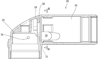
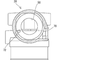
- FIG. 2 is a longitudinal sectional view of the housing of the air grinder of FIG. 1, and the air blowing holes do not actually appear in this figure, but are shown in phantom lines to indicate their positions. It is the III-III sectional view taken on the line of FIG. It is a partially notched top view of the air grinder.
- FIG. 1 shows an air grinder 10 which is a rotary drive air tool according to the present invention.
- the air grinder 10 includes an air motor 14 having a rotation output shaft 12, a rotation transmission mechanism 18 having a rotation transmission shaft 16 that transmits a rotational driving force of the rotation output shaft 12 to a polishing disk (rotary tool member) 15, and an air motor 14.
- the air motor 14 is formed integrally with the cylindrical casing 26 fixedly supported in the motor chamber 20 of the housing 28, end walls 30 provided at both ends of the cylindrical casing 26, and the rotary output shaft 12.
- a rotor 35 is rotatably supported by a radial bearing 32 provided on the wall 30 and is rotatable in a rotor chamber defined by the cylindrical casing 26 and the end wall 30.
- the rotor 35 has slits 34 provided at regular intervals in the circumferential direction and extending in the radial direction and the axial direction, and a blade 36 is provided in the groove so as to be displaceable in the radial direction. As the rotor rotates, the blade 36 rotates while sliding on the inner peripheral surface of the cylindrical casing 26.
- the rotation transmission shaft 16 is rotatably supported in the rotation transmission chamber 22 by a needle bearing 46 and a radial bearing 48, has a bevel gear 40 at its upper end, and is attached to the rotation output shaft of the air motor 14. It is drivingly engaged with the gear 42.
- the right end portion of the housing 28 as viewed in FIG. 1 is connected to a compressor (not shown), and high-pressure air is introduced through the opening / closing valve device 52. That is, a plurality of air intake holes 56 penetrating in the left-right direction are formed in the right end portion of the housing 28 at intervals in the circumferential direction (only one is shown in FIG. 1).
- the rotary valve member 54 is rotatably in contact with the right end surface of the housing 28, and the rotary valve member closes the air intake hole 56 as shown in the figure, and the rotary valve member 54 is illustrated.
- the non-communication hole is aligned with the air intake hole 56 so that the air intake hole 56 can be displaced between an open position for receiving high-pressure air from the air pump.
- the rotary valve member 54 is connected to the operation sleeve 62 via the connecting shafts 58 and 60, and is rotated between the open position and the closed position by rotating the operation sleeve 62.
- reference numeral 64 denotes a fixed shaft that engages with the operation sleeve 62 to prevent the operation sleeve from rotating.
- the operation sleeve 62 is opposed to the coil spring 66 in FIG. Displace from the position to the left and disengage from the fixed shaft.
- the high-pressure air that has passed through the air intake hole 56 passes around the governor 65 fixed to the shaft extending rightward from the rotor 35, is supplied to the rotor chamber through a path (not shown), and rotates the rotor. Thereafter, the air is discharged into an annular space between the cylindrical casing 26 and the housing 28 through an exhaust hole (not shown) penetrating the cylindrical casing 26 of the air motor, and through an air discharge opening 70 provided through the housing 28. It is discharged outside.
- FIG. 2 shows only the housing 28 of the air grinder shown in FIG. 1, and FIG. 3 shows a sectional view taken along the line III-III.
- the partition wall 24 between the motor chamber 20 and the rotation transmission chamber 22 is provided with a circular opening 50 through which the rotation output shaft of the air motor passes in the center, and the partition wall 24 has a substantially annular shape.
- the partition wall 24 is provided with an air blowing hole 72 that passes through the partition wall 24 and supplies a part of the high-pressure air discharged into the annular space between the cylindrical casing 26 and the housing 28 to the rotation transmission chamber 22. It is formed (FIGS. 3 and 4).
- the air blowing hole 72 has an upward conical surface 40 in which a plurality of teeth of the bevel gear 40 are provided so that air blown into the rotation transmission chamber 22 does not hit the bevel gear 42.
- -1 is blown in the tangential direction to the substantially cylindrical peripheral wall surface 22-1 of the rotation transmission chamber 22 through the outer peripheral edge portion of the rotation transmission chamber 22, and the rotation transmission chamber is swirled along the peripheral wall surface. 22 is opened in the peripheral wall surface.
- the peripheral wall of the rotation transmission chamber 22 is positioned slightly below the air blowing hole 72 (specifically, the cylindrical peripheral surface 40 continuing below the conical surface 40-1 of the bevel gear).
- Air discharge hole 76 is formed at a position opposite to -2, and the air discharge hole 76 communicates with the air discharge opening 70 to discharge the air supplied to the rotation transmission chamber 22 to the outside. It is like that.
- the air discharge hole 76 is provided at a position with a slight gap with respect to the cylindrical peripheral surface 40-2 of the bevel gear 40, and is supplied from the air blowing hole 72 into the rotation transmission chamber. While the air swirls in the space above the conical surface of the bevel gear 40, the grease blown off from the bevel gear and adhered to the inner peripheral wall surface of the housing part around it is blown off from the wall surface or blown off from the bevel gear. The grease is prevented from adhering to the peripheral wall surface, and the grease is discharged from the air discharge hole 76 after returning the grease to the bevel gear.
- reference numeral 78 denotes a handle that is held by the worker during work.
- the present invention is not limited to the grinder and can be applied to other rotationally driven air tools.
Landscapes
- Engineering & Computer Science (AREA)
- Mechanical Engineering (AREA)
- Finish Polishing, Edge Sharpening, And Grinding By Specific Grinding Devices (AREA)
- Portable Power Tools In General (AREA)
Priority Applications (3)
| Application Number | Priority Date | Filing Date | Title |
|---|---|---|---|
| KR1020117019032A KR101352279B1 (ko) | 2009-02-18 | 2010-02-16 | 회전 구동 에어 공구 |
| CN201080008156.4A CN102325631B (zh) | 2009-02-18 | 2010-02-16 | 转动驱动空气工具 |
| US13/208,773 US8297374B2 (en) | 2009-02-18 | 2011-08-12 | Rotationally driven air tool |
Applications Claiming Priority (2)
| Application Number | Priority Date | Filing Date | Title |
|---|---|---|---|
| JP2009034803A JP5243294B2 (ja) | 2009-02-18 | 2009-02-18 | 回転駆動エア工具 |
| JP2009-034803 | 2009-02-18 |
Related Child Applications (1)
| Application Number | Title | Priority Date | Filing Date |
|---|---|---|---|
| US13/208,773 Continuation US8297374B2 (en) | 2009-02-18 | 2011-08-12 | Rotationally driven air tool |
Publications (1)
| Publication Number | Publication Date |
|---|---|
| WO2010095613A1 true WO2010095613A1 (ja) | 2010-08-26 |
Family
ID=42633893
Family Applications (1)
| Application Number | Title | Priority Date | Filing Date |
|---|---|---|---|
| PCT/JP2010/052273 Ceased WO2010095613A1 (ja) | 2009-02-18 | 2010-02-16 | 回転駆動エア工具 |
Country Status (6)
| Country | Link |
|---|---|
| US (1) | US8297374B2 (enExample) |
| JP (1) | JP5243294B2 (enExample) |
| KR (1) | KR101352279B1 (enExample) |
| CN (1) | CN102325631B (enExample) |
| TW (1) | TWI429521B (enExample) |
| WO (1) | WO2010095613A1 (enExample) |
Cited By (2)
| Publication number | Priority date | Publication date | Assignee | Title |
|---|---|---|---|---|
| JP2016006308A (ja) * | 2014-06-20 | 2016-01-14 | 日東工器株式会社 | エアモータ、及びエアモータを備えるエア工具 |
| TWI663030B (zh) * | 2018-08-08 | 2019-06-21 | 益航電子股份有限公司 | 傳動軸及周邊結構 |
Families Citing this family (8)
| Publication number | Priority date | Publication date | Assignee | Title |
|---|---|---|---|---|
| KR101379952B1 (ko) * | 2012-06-08 | 2014-03-28 | 삼성중공업 주식회사 | 에어 그라인더 |
| JP6217051B2 (ja) * | 2012-07-03 | 2017-10-25 | アトラス・コプコ・インダストリアル・テクニーク・アクチボラグ | 動力工具 |
| USD724922S1 (en) * | 2013-04-20 | 2015-03-24 | Eder Alamilla | Grinder attachment |
| US9289878B2 (en) | 2013-08-30 | 2016-03-22 | Ingersoll-Rand Company | Grinders with friction drives |
| US10293472B2 (en) * | 2014-05-16 | 2019-05-21 | Robert Bosch Tool Corporation | Speed limiting governor of a rotating shaft in air |
| KR101594594B1 (ko) * | 2014-12-10 | 2016-02-26 | 양산기공 주식회사 | 에어 공구용 밸브 |
| TWI617391B (zh) | 2016-01-25 | 2018-03-11 | Nitto Kohki Co., Ltd. | 氣動工具 |
| JP7338535B2 (ja) * | 2020-03-31 | 2023-09-05 | 工機ホールディングス株式会社 | 作業機 |
Citations (3)
| Publication number | Priority date | Publication date | Assignee | Title |
|---|---|---|---|---|
| JPS5683362U (enExample) * | 1979-11-30 | 1981-07-04 | ||
| JPH0639745A (ja) * | 1992-06-16 | 1994-02-15 | Atlas Copco Tools Ab | 空気動力工具用調速器 |
| JP2005329510A (ja) * | 2004-05-20 | 2005-12-02 | Big Tool Co Ltd | 手持ち式切削装置 |
Family Cites Families (10)
| Publication number | Priority date | Publication date | Assignee | Title |
|---|---|---|---|---|
| US3719254A (en) * | 1971-11-10 | 1973-03-06 | Dotco Inc | Lubricated angle drive attachment for air operated tool |
| US4403679A (en) * | 1981-04-01 | 1983-09-13 | Cooper Industries, Inc. | Angle drive lubricator |
| US5052496A (en) * | 1989-10-11 | 1991-10-01 | Ingersoll-Rand Company | Apparatus for attaching power tool housing extensions |
| SE510972C2 (sv) * | 1996-05-07 | 1999-07-19 | Atlas Copco Tools Ab | Portabelt kraftverktyg med balanseringsanordning |
| SE509564C2 (sv) * | 1997-02-19 | 1999-02-08 | Atlas Copco Tools Ab | Motorverktyg med smord vinkelväxel |
| US6158528A (en) * | 2000-01-27 | 2000-12-12 | S.P. Air Kabusiki Kaisha | Hand-held pneumatic rotary drive device |
| SE523815C2 (sv) * | 2002-05-22 | 2004-05-18 | Atlas Copco Tools Ab | Portabelt kraftverktyg med fettsmord vinkelväxel med separat fettomfördelningselement |
| JP5059313B2 (ja) | 2005-10-07 | 2012-10-24 | 日本ニューマチック工業株式会社 | エアツール |
| SE0602575L (sv) * | 2006-12-01 | 2007-11-13 | Atlas Copco Tools Ab | Kylsystem för pneumatiskt verktyg |
| TWI386279B (zh) * | 2007-01-11 | 2013-02-21 | Sp Air Kabushiki Kaisha | 具有可旋轉頭之刻模機 |
-
2009
- 2009-02-18 JP JP2009034803A patent/JP5243294B2/ja active Active
-
2010
- 2010-02-12 TW TW099104735A patent/TWI429521B/zh active
- 2010-02-16 CN CN201080008156.4A patent/CN102325631B/zh active Active
- 2010-02-16 KR KR1020117019032A patent/KR101352279B1/ko active Active
- 2010-02-16 WO PCT/JP2010/052273 patent/WO2010095613A1/ja not_active Ceased
-
2011
- 2011-08-12 US US13/208,773 patent/US8297374B2/en active Active
Patent Citations (3)
| Publication number | Priority date | Publication date | Assignee | Title |
|---|---|---|---|---|
| JPS5683362U (enExample) * | 1979-11-30 | 1981-07-04 | ||
| JPH0639745A (ja) * | 1992-06-16 | 1994-02-15 | Atlas Copco Tools Ab | 空気動力工具用調速器 |
| JP2005329510A (ja) * | 2004-05-20 | 2005-12-02 | Big Tool Co Ltd | 手持ち式切削装置 |
Cited By (2)
| Publication number | Priority date | Publication date | Assignee | Title |
|---|---|---|---|---|
| JP2016006308A (ja) * | 2014-06-20 | 2016-01-14 | 日東工器株式会社 | エアモータ、及びエアモータを備えるエア工具 |
| TWI663030B (zh) * | 2018-08-08 | 2019-06-21 | 益航電子股份有限公司 | 傳動軸及周邊結構 |
Also Published As
| Publication number | Publication date |
|---|---|
| KR101352279B1 (ko) | 2014-01-16 |
| US20110297412A1 (en) | 2011-12-08 |
| TWI429521B (zh) | 2014-03-11 |
| TW201032967A (en) | 2010-09-16 |
| JP2010188463A (ja) | 2010-09-02 |
| US8297374B2 (en) | 2012-10-30 |
| JP5243294B2 (ja) | 2013-07-24 |
| KR20110103472A (ko) | 2011-09-20 |
| CN102325631B (zh) | 2014-02-05 |
| CN102325631A (zh) | 2012-01-18 |
Similar Documents
| Publication | Publication Date | Title |
|---|---|---|
| JP5243294B2 (ja) | 回転駆動エア工具 | |
| JP2010188463A5 (enExample) | ||
| CN112739503B (zh) | 便携式动力工具 | |
| US8857536B2 (en) | Hand-held power tool | |
| US8490715B2 (en) | Hand-held machine tool | |
| JP2019524457A (ja) | 手持ち式電動工具装置、および、手持ち式電動工具 | |
| TW201713879A (zh) | 動力工具 | |
| CN102905852A (zh) | 具有机械冲击机构的手持式工具机 | |
| CN102458738A (zh) | 手持式电动工具 | |
| US8439662B2 (en) | Vane air motor | |
| US6880223B2 (en) | Grease slinger | |
| CN105562771A (zh) | 手持式工具机装置 | |
| JP6217850B2 (ja) | 打撃工具 | |
| GB2448616A (en) | A lubrication distribution device | |
| CN205464445U (zh) | 动力工具 | |
| EP3514407B1 (en) | Power tool | |
| TW202218828A (zh) | 具有齒輪系的氣動工具 | |
| JP6494805B2 (ja) | エア工具 | |
| JP3234181U (ja) | エルボー式動力工具 | |
| KR200299217Y1 (ko) | 드릴겸용 그라인더 | |
| US20080014086A1 (en) | Turbo pneumatic cylinder of pneumatic tool | |
| EP2378061B1 (en) | Vane-type air motor | |
| JP2007098539A (ja) | エアツール | |
| JP2008200334A (ja) | 医科歯科用ハンドピース | |
| SE0002644D0 (sv) | Bärbar, handmanövrerad arbetsmaskin samt maskinelement för arbetsmaskinen |
Legal Events
| Date | Code | Title | Description |
|---|---|---|---|
| WWE | Wipo information: entry into national phase |
Ref document number: 201080008156.4 Country of ref document: CN |
|
| 121 | Ep: the epo has been informed by wipo that ep was designated in this application |
Ref document number: 10743739 Country of ref document: EP Kind code of ref document: A1 |
|
| ENP | Entry into the national phase |
Ref document number: 20117019032 Country of ref document: KR Kind code of ref document: A |
|
| NENP | Non-entry into the national phase |
Ref country code: DE |
|
| 122 | Ep: pct application non-entry in european phase |
Ref document number: 10743739 Country of ref document: EP Kind code of ref document: A1 |