WO2010095481A1 - ゲーム装置 - Google Patents
ゲーム装置 Download PDFInfo
- Publication number
- WO2010095481A1 WO2010095481A1 PCT/JP2010/050469 JP2010050469W WO2010095481A1 WO 2010095481 A1 WO2010095481 A1 WO 2010095481A1 JP 2010050469 W JP2010050469 W JP 2010050469W WO 2010095481 A1 WO2010095481 A1 WO 2010095481A1
- Authority
- WO
- WIPO (PCT)
- Prior art keywords
- lottery
- game
- unit
- specific control
- bet
- Prior art date
- Legal status (The legal status is an assumption and is not a legal conclusion. Google has not performed a legal analysis and makes no representation as to the accuracy of the status listed.)
- Ceased
Links
Images








Classifications
-
- G—PHYSICS
- G07—CHECKING-DEVICES
- G07F—COIN-FREED OR LIKE APPARATUS
- G07F17/00—Coin-freed apparatus for hiring articles; Coin-freed facilities or services
- G07F17/32—Coin-freed apparatus for hiring articles; Coin-freed facilities or services for games, toys, sports, or amusements
- G07F17/3286—Type of games
- G07F17/329—Regular and instant lottery, e.g. electronic scratch cards
-
- G—PHYSICS
- G07—CHECKING-DEVICES
- G07C—TIME OR ATTENDANCE REGISTERS; REGISTERING OR INDICATING THE WORKING OF MACHINES; GENERATING RANDOM NUMBERS; VOTING OR LOTTERY APPARATUS; ARRANGEMENTS, SYSTEMS OR APPARATUS FOR CHECKING NOT PROVIDED FOR ELSEWHERE
- G07C15/00—Generating random numbers; Lottery apparatus
- G07C15/001—Generating random numbers; Lottery apparatus with balls or the like
-
- G—PHYSICS
- G07—CHECKING-DEVICES
- G07F—COIN-FREED OR LIKE APPARATUS
- G07F17/00—Coin-freed apparatus for hiring articles; Coin-freed facilities or services
- G07F17/32—Coin-freed apparatus for hiring articles; Coin-freed facilities or services for games, toys, sports, or amusements
- G07F17/3244—Payment aspects of a gaming system, e.g. payment schemes, setting payout ratio, bonus or consolation prizes
-
- G—PHYSICS
- G07—CHECKING-DEVICES
- G07F—COIN-FREED OR LIKE APPARATUS
- G07F17/00—Coin-freed apparatus for hiring articles; Coin-freed facilities or services
- G07F17/32—Coin-freed apparatus for hiring articles; Coin-freed facilities or services for games, toys, sports, or amusements
- G07F17/34—Coin-freed apparatus for hiring articles; Coin-freed facilities or services for games, toys, sports, or amusements depending on the stopping of moving members in a mechanical slot machine, e.g. "fruit" machines
-
- G—PHYSICS
- G07—CHECKING-DEVICES
- G07C—TIME OR ATTENDANCE REGISTERS; REGISTERING OR INDICATING THE WORKING OF MACHINES; GENERATING RANDOM NUMBERS; VOTING OR LOTTERY APPARATUS; ARRANGEMENTS, SYSTEMS OR APPARATUS FOR CHECKING NOT PROVIDED FOR ELSEWHERE
- G07C15/00—Generating random numbers; Lottery apparatus
Definitions
- the present invention relates to a so-called betting game device installed in a game facility such as a game center or a casino.
- Patent Document 1 describes a slot machine that stops rotation of a plurality of reels (symbol display units) each having a plurality of types of symbols and aligns symbols related to predetermined roles on a winning line. .
- the count value of the counter is incremented by 1, and the number corresponding to the count value The process of lighting the lamp is performed.
- the count value is the same as the number of lamps and all the lamps are lit, the game progresses so that the player can earn more medals than in the normal game mode. Transition.
- the player plays the game with the expectation that all the lamps are turned on in order to shift to the special game mode that is more advantageous than the normal game mode.
- the game will shift to the special game mode.
- the speculation that play in the game mode is possible works, and there is an effect that keeps the player trying to finish the play.
- betting game devices that use tokens such as money or medals, coins, pachinko balls, etc. as betting objects or payout objects, such as slot machines, that can change the amount of betting objects for each game.
- the game is designed so that the larger the amount of bet objects, the larger the amount of payout objects.
- variable bet configuration it is possible to satisfy both the demands of a player who desires a high risk and a high return and a player who desires a low risk and a low return with a single game device.
- a predetermined progress result in a plurality of games in the case of the slot machine described in Patent Document 1, the result that stock symbols (specific symbols) are aligned on the winning line
- the betting game device that is the start condition of the specific control (in the case of the slot machine described in Patent Document 1, the control in the special game mode)
- a predetermined progress result related to the start condition of the specific control is generated.
- a configuration is desired in which the payout amount to be paid out by the specific control is changed according to the bet amount of the game.
- variable bet configuration a single game device satisfies the needs of both a player who desires high risk and high return by specific control and a player who desires low risk and low return by specific control. It is because the effect that it becomes possible is acquired.
- the higher the bet target amount the higher the bet target amount.
- the bet amount of the game when the start condition for the specific control is satisfied That is, if the bet amount of the last game among a plurality of games that has produced a predetermined progress result is used as a reference, the last game among the plurality of games for satisfying the start condition of the specific control
- the bet amount for the previous game does not affect the amount to be paid out by the specific control.
- the present invention relates to a betting game apparatus in which a predetermined progress result in a plurality of games is used as a start condition for specific control, in accordance with the bet amount of the game that caused the predetermined progress result related to the start condition for the specific control. It is possible to provide a game apparatus capable of achieving a target effect by changing the amount of payout target to be paid out by specific control.
- an operation accepting unit that accepts a player's operation
- a bet object accepting unit that performs a bet accepting process for accepting an amount of bet object that can be changed according to the bet amount operation accepted by the operation accepting unit
- a game progress control unit that controls the progress of a game that is repeatedly performed by executing a predetermined game progress program as a game start condition that the betting object receiving unit performs a bet receiving process
- the game progress control unit includes:
- a game apparatus comprising: a payout processing unit that performs a payout process of paying out a payout object according to the amount of a bet object received by the betting object accepting unit according to a progress result of the game to be controlled.
- a counting unit that counts the specific control start condition count value according to the progress result of the game controlled by the A cumulative bet amount storage unit for storing the cumulative amount of the betting object bet in the game when the game unit counts the specific control start condition count value, and the specific control start condition count value satisfies a predetermined specific control start condition
- the specific control execution unit that starts the specific control and the payout processing unit according to the specific control by the specific control execution unit, the amount according to the accumulated amount of the betting object stored in the accumulated bet amount storage unit A payout process for paying out a payout object is performed.
- the specific control start condition count value related to the specific control start condition is counted according to the progress result of the game controlled by the game progress control unit.
- the specific control start condition count value for satisfying the specific control start condition is counted according to the cumulative amount of bets to bet in the game.
- the amount to be paid out is paid out.
- the present game device it is possible to satisfy both the demands of a player who desires a high risk and high return by specific control and a player who desires a low risk and low return by specific control with a single game device. Furthermore, it is possible to cause the player to play the game by thinking about the bet amount strategically by combining the low risk low return and the high risk high return in each game.
- the specific control performed by the specific control execution unit is a control for performing lottery for determining whether or not a predetermined prize is won
- the payout processing unit includes the specific control execution unit.
- the payout process of paying out an amount of payout object corresponding to the accumulated amount of the bet object stored in the bet accumulated amount storage unit is performed. May be. Since this game device is a so-called betting game device, the payout amount to be paid out when a predetermined prize is won in a lottery started satisfying the specific control start condition is specified to satisfy the specific control start condition.
- the expected payout rate of the payout target may be substantially constant even if the cumulative amounts are different. desired. This is because if there is a large difference in the expected value of the payout rate depending on the accumulated amount of the betting object, the betting object will be betted only in the amount with the highest expected value of the payout rate. According to the present game device, even if the cumulative amount of bet objects is different, the expected value of the payout rate of the payout object to be paid out when winning a predetermined prize by lottery by specific control is prevented from greatly fluctuating. It becomes possible.
- the lottery may be a physical lottery using a lottery object.
- the lottery by the specific control can be performed by the physical lottery in which the player can easily obtain the trust rather than the computer lottery, the reliability of the lottery by the specific control can be improved.
- the game progress control unit variably displays a plurality of types of symbols on a predetermined display unit and then stops the variable display, the combination of the predetermined symbols is placed on the winning line.
- the stop display is made, the progress of the slot game in which the amount of payout target corresponding to the combination of symbols is paid out to the player is increased so that the number of pay lines increases as the amount of bet targets received by the betting target reception unit increases.
- the counting unit counts the specific control start condition count value according to the progress result of the slot game that the special symbol combination is stopped and displayed on the winning line. Good. Usually, the player feels that it becomes easier to win if the number of winning lines is large.
- this game device it is possible to make the player feel that the specific control is easily started when the amount of the betting target is increased, and the payout of the payout target by the specific control is easily received. Therefore, it can be expected that the player bets more bets.
- a second count unit that counts a second specific control start condition count value according to a progress result of the game controlled by the game progress control unit, and the second count unit includes a second count unit.
- a second accumulated bet amount storage unit that stores an accumulated amount of a bet object bet in the game when the specific control start condition count value is counted
- the specific control execution unit includes the specific control start condition count value Alternatively, when any one of the second specific control start condition count values starts the specific control by satisfying a predetermined specific control start condition, and the specific control start condition count value satisfies a predetermined specific control start condition Performs a process of resetting the specific control start condition count value while maintaining the second specific control start condition count value, There if it meets a predetermined specific control start conditions, while maintaining the specific control start condition count value, the second specific control start condition count value may perform a process of resetting.
- a single game device satisfies the needs of both the player who desires high risk and high return by specific control and the player who desires low risk and low return by specific control. It becomes possible.
- FIG. 1 is a partial perspective view showing the overall configuration of the medal game machine according to the embodiment.
- FIG. 2 is a perspective view showing an upper portion of the station portion in the medal game machine.
- FIG. 3 is an explanatory diagram showing an example of a dual play mode game screen displayed on the touch panel of the station unit.
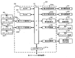
- FIG. 4 is a block diagram showing a schematic configuration of a station control device that controls the station unit.
- FIG. 5 is a functional block diagram showing functions of the station unit and the center lottery device.
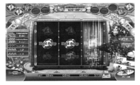
- FIG. 6 is an explanatory diagram showing an example of a game screen in single play mode displayed on the touch panel of the station unit.
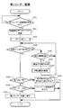
- FIG. 7 is a flowchart showing the flow of one slot game executed in the station unit.
- FIG. 1 is a partial perspective view showing the overall configuration of the medal game machine according to the embodiment.
- FIG. 2 is a perspective view showing an upper portion of the station portion in the medal game machine.
- FIG. 3 is an explanatory diagram showing an example of a dual play
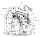
- FIG. 8 is a perspective view of a center lottery device in the medal game machine.
- FIG. 9 is a perspective view when the center lottery apparatus is viewed from an angle different from that of FIG. 8.
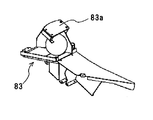
- FIG. 10 is an explanatory view showing a state in which the shutter provided in the ball insertion standby unit 83 of the inclined ring lottery unit in the center lottery apparatus has released the lottery ball.
- FIG. 11 is a block diagram showing a schematic configuration of a main part of the central control device that controls the center lottery device.
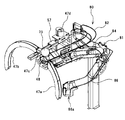
- FIG. 12 is a perspective view showing the overall configuration of the ball transfer device in the center lottery device.
- FIG. 13 is a perspective view for explaining the ball transport device and its peripheral configuration.
- FIG. 14 is a side view for explaining the ball conveying device and its peripheral configuration.
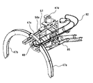
- FIG. 15 is an explanatory view showing a state in which the shutter provided in the first ball discharge unit of the vertical ring lottery unit is located at the ball passing position.
- FIG. 16 is an explanatory diagram showing a state in which the shutter is located at the ball discharge position.
- FIG. 17 is an explanatory diagram illustrating a state in which the shutter provided at the dropping port in the middle of the first transport rail is located at the closed position.
- FIG. 18 is an explanatory diagram showing a state in which the shutter is positioned at the opening position.
- FIG. 19 is an explanatory diagram showing a transport path switching device in a standby state in the ball transport apparatus.
- FIG. 20 is an explanatory diagram showing a transport path switching device when a lottery ball is sent to the first outlet.
- FIG. 21 is an explanatory diagram showing a transport path switching device when a lottery ball is sent out to the second outlet.
- FIG. 22 is a perspective view showing a configuration of a second pattern sensor provided in the inclined ring lottery machine.
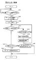
- FIG. 23 is a flowchart showing the flow of one first center lottery.
- FIG. 24 is a flowchart showing the flow of one second center lottery.
- FIG. 25 is an explanatory diagram showing an example of a game screen in another example of the game that can be executed in the station unit.
- FIG. 1 is a partial perspective view showing the overall configuration of the medal game machine 1 according to the present embodiment.
- the medal game machine 1 includes eight station units 2 so as to surround a center lottery device 3 which is a physical lottery device as a lottery unit functioning as a lottery means.
- one station unit 2 is configured to be able to execute two independent games that proceed independently of each other, and a maximum of 16 players can play simultaneously.
- FIG. 2 is a perspective view showing an upper portion of the station unit 2 in the medal game machine 1.
- the station unit 2 includes a touch panel 11 serving as a display unit and an operation receiving unit functioning as a display unit and an operation receiving unit, two start buttons 12 serving as an operation receiving unit functioning as an operation receiving unit, and a bet mode.
- a selection button 13 and a medal slot 14 are provided.
- the touch screen 11 displays game screens of two independent games that are progressing independently from each other side by side, and the two players see the touch screen 11 and the display of the respective game screens. The game is played by operating the various buttons 12 and 13.
- the two independent games executed in the station unit 2 are slot games (symbol matching games) will be described as an example.
- the types of independent games executed in the station unit 2 are described here. Not limited.
- the slot game refers to a symbol that is displayed in a variable manner when a plurality of types of symbols (designs) are variably displayed and then the variable display is stopped, or a combination of a plurality of symbols that are stopped and displayed.
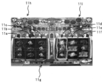
- FIG. 3 is an explanatory diagram illustrating an example of two game screens displayed on the touch panel 11 of the station unit 2.
- the touch panel 11 On the two game screens displayed on the touch panel 11, two or more kinds of symbols arranged in a predetermined order are displayed in the three symbol display areas 11a to 11c and 11d to 11f, respectively.
- the touch panel 11 also displays various information necessary for the game, such as a credit display unit that displays a credit amount corresponding to the number of medals inserted by the player from the medal slot 5a at the bottom of the game screen.
- the display part 11g to display is also displayed.
- two players who play in one station unit 2 play using a common credit to each other, so there is one credit display unit displayed on the display unit 11g.
- a bet amount display unit that displays a bet (BET) amount
- a credit acquisition amount display unit that displays a payout amount at the time of winning, etc.
- some or all of the operations other than the operations on the mechanical buttons 12 and 13 are performed by touching various operation images displayed on the touch panel 11.
- a mechanical button may be provided, or conversely, an operation image on the touch panel 11 may be used instead of the mechanical buttons 12 and 13.
- the station unit 2 is a station control device composed of an electronic circuit formed by a CPU, a ROM, and other various electronic components, and an inspection for confirming whether the received medal is an illegal medal.
- a device, a medal withdrawal device that can accommodate a large number of medals and discharges the number of medals instructed from the station control device to the outside, and a speaker as a sound output unit that functions as a sound output means are also incorporated. .
- FIG. 4 is a block diagram illustrating a schematic configuration of the station control device 20 that controls the station unit 2.
- the station control device 20 includes a CPU 21, an input / output port 21a, a ROM 22, a RAM 23, a random number generation circuit 24, a display control unit 25, an acoustic control unit 26, a payout control unit 27, and the like.
- the input / output port 21a is used for data communication with a central control device 30 described later.
- the ROM 22 stores data such as various programs used by the CPU 21 and various databases, and outputs these to the CPU 21.
- the RAM 23 temporarily stores variable data calculated by the CPU 21 and stores various fluctuation data such as credit data.
- the random number generation circuit 24 generates a random number at a predetermined timing and outputs the data to the CPU 21.
- the display control unit 25 constitutes a display unit together with the touch panel 11, and performs display control of the touch panel 11 that displays a game screen and the like under the control of the CPU 21.
- the sound control unit 26 controls announcements, production sounds, and the like by sound output from the speaker 15 under the control of the CPU 21.
- the payout control unit 27 controls the medal payout device 16 to pay back medals under the control of the CPU 21.
- the CPU 21 is also connected to a medal counter (not shown) that counts the number of medals inserted into the medal slot, an illumination control unit that controls illumination such as an LED, and the like.
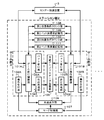
- FIG. 5 is a functional block diagram showing functions of the station unit 2 and the center lottery apparatus 3 related to the characteristic part of the present invention.
- one station unit 2 includes a game unit A and a game unit B that respectively execute two independent games that proceed independently of each other.
- These game units A and B include game progress control units 101A and 101B as game progress control units that function as game progress control means for controlling the progress of each independent game.
- These two game progress control units 101A and 101B may be configured by physically different hardware such as game boards, or virtually by two software that operates independently on the same hardware. It may be configured as follows. Alternatively, the two game progress control units 101A and 101B may be configured virtually by a single software operating on the same hardware. The configurations of the game units A and B are the same.
- the game units A and B mainly have game progress control units 101A and 101B as game progress control units that function as game progress control units, and operation reception units 102A and 102B as operation reception units that function as operation reception units. And bet receiving units 103A and 103B as bet target receiving units that function as bet target receiving units, and payout processing units 104A and 104B as payout units that function as payout units, respectively.
- a common credit data storage unit 105 as a common credit data storage unit that functions as a common credit data storage unit that stores credit data indicating the amount of credit used as a bet object and a payout object in each game unit A, B
- the common display unit 106 serving as a display unit that functions as a display unit for displaying the game screen is configured to be shared by the two game units A and B.
- the game progress control units 101A and 101B are configured by the CPU 21, ROM 22, RAM 23, random number generation circuit 24, and the like.
- the game operation control units 101A and 101B perform game operations received by the operation reception units 102A and 102B. Accordingly, the game progress control is performed independently so as to change the progress of the game based on the game program being executed.
- the game progress control units 101A and 101B also perform control to display a game screen corresponding to the progress of each game on the touch panel 11 of the common display unit 106 or to output a sound such as a production sound from the speaker 15. Do.
- the independent games that are controlled by the game progress control units 101A and 101B according to the present embodiment are slot games.
- the bet accepting units 103A and 103B store the common credit data stored in the common credit data storage unit 105 according to the bet operation.
- the slot game is started by subtracting from the credit amount indicated by. Then, the progress control of the slot game including the control for deciding to pay out the credit according to the result of the slot game is performed.
- the game progress control units 101A and 101B in the present embodiment provide a plurality of specific control start condition count values (this embodiment) to the first lottery condition count unit 108 and the second lottery condition count unit 110 according to the game progress. In the embodiment, the game progress is controlled so that five lottery condition flags are sequentially counted one by one.
- a configuration is used in which the count value of the specific control start condition is counted by recording five lottery condition flags, but a configuration in which one count value data is simply counted up. It is good.
- the arrangement or combination of the flags can be included in the first center lottery start condition described later. For example, in a configuration in which five lottery condition flags are randomly recorded according to the progress of the game, the condition that three adjacent flags are recorded can be set as the first center lottery start condition. .
- the operation receiving units 102A and 102B are configured by a touch panel 11, two start buttons 12, a bet mode selection button 13, and the like. When an operation is performed by each player, an operation signal is sent to the CPU 21 of the station control device 20.
- the bet receiving units 103A and 103B are configured by the CPU 21, ROM 22, RAM 23, and the like, and when the corresponding operation receiving units 102A and 102B receive a bet operation (bet amount operation), the bet amount corresponding to the bet operation is shared credits.
- a bet acceptance process for subtracting the credit amount indicated by the common credit data stored in the data storage unit 105 is performed.
- the payout processing units 104A and 104B are constituted by the CPU 21, the ROM 22, the RAM 23, and the like, and the credit amount received by the corresponding bet receiving units 103A and 103B according to the progress result of the game controlled by the corresponding game progress control units 101A and 101B.
- a payout process is performed in which the credit corresponding to the credit amount is added to the credit amount indicated by the common credit data stored in the common credit data storage unit 105.
- the common credit data storage unit 105 includes a RAM 23 and the like, and stores credit data indicating the amount of credits commonly used by players playing in the game units A and B in the common credit storage area of the RAM 23.
- the common display unit 106 includes the display control unit 25, the touch panel 11, and the like, and displays two game screens corresponding to the progress of each independent game controlled by each game progress control unit 101A, 101B. The two game screens are displayed on the respective screen areas by dividing the screen area on the touch panel 11 into left and right parts. Further, when the mode is switched to the single play mode by the mode switching unit 107 described later, as shown in FIG. 6, one of the game progress control units 101A and 101B controlled by the independent game progress is controlled. Display only the game screen. In this case, this game screen is displayed on the entire screen area on the touch panel 11.
- the station unit 2 of the present embodiment includes a mode switching unit 107 as a mode switching unit that functions as a mode switching unit, a first lottery condition counting unit 108 as a counting unit that functions as a counting unit, and a cumulative bet amount storage unit.
- a first bet cumulative amount storage unit 109 serving as a functioning bet cumulative amount storage unit
- a second lottery condition counting unit 110 serving as a second count unit functioning as a second counting unit
- a second function serving as a second bet cumulative amount storage unit.
- a second bet cumulative amount storage unit 111 is provided as a two bet cumulative amount storage unit. These are configured to be shared by the two game units A and B.
- the mode switching unit 107 includes a CPU 21, a ROM 22, a RAM 23, and the like.
- the mode switching unit 107 has 2 Two game screens are displayed and each game progress control unit 101A, 101B controls the progress of the independent game, so that two players can play simultaneously, and one game screen is displayed on the common display unit 106. Only one of the game units A and B controls the progress of the independent game to switch the single play mode to be played by only one player.
- the other game screen which is not the player's game screen occupies the screen area of the touch panel 11 without being used. Since the screen area of the touch panel 11 is limited, in the dual play mode using the game screen obtained by dividing the limited screen area into two, the game screen is too narrow, and there is a problem such as lack of dynamic of the display by the image display. is there. On the other hand, by providing the single play mode as described above, a game screen that is not used when playing alone is excluded from the screen area of the touch panel 11, and the limited screen area is effectively used to The game screen used by the player can be displayed. As a result, a more dynamic performance is possible.
- the first lottery condition count unit 108 and the second lottery condition count unit 110 are configured by the CPU 21, the ROM 22, the RAM 23, and the like, and 5 according to the progress results of both independent games controlled by the game progress control units 101A and 101B.
- the first lottery condition flag which is one specific control start condition flag is sequentially recorded one by one.
- the first lottery condition counting unit 108 sets five first lottery condition flags for any independent game if a predetermined game progress result for counting up the first lottery condition counting unit 108 is obtained. Record one by one sequentially.
- an example in which five lottery condition flags are sequentially recorded one by one will be described.
- the counting method of the specific control start condition count value (five lottery condition flag recording methods) is Not limited to this, a plurality of lottery condition flags may be recorded at a time according to one game progress result, or the lottery condition flags may be erased depending on the game progress result.
- the lottery condition flag is maintained without being reset even when the mode switching unit 107 described above switches from the dual play mode to the single play mode or from the single play mode to the dual play mode. Thereby, the effect of prompting the second player to participate while one player is playing in the single play mode can be expected. In addition, for example, even if one player finishes the game play and switches to the single play mode while two players are playing in the dual play mode, there is no disadvantage to the remaining players. Can be expected to promote the use of dual play mode.
- the first bet cumulative amount storage unit 109 and the second bet cumulative amount storage unit 111 are constituted by the RAM 23 and the like, and credits betted in the independent game when the corresponding lottery condition count units 108 and 110 record the lottery condition flag. Is stored.
- a bet history indicating the credit amount betted in the independent game when the lottery condition flag is recorded is stored in association with each lottery condition flag. Even if stored in such a format, the cumulative amount can be obtained by accumulating the bet history associated with each lottery condition flag, so that the corresponding lottery condition counting units 108 and 110 can display the lottery condition flag. It can be said that the cumulative amount of credits betted in the independent game when the record is recorded is stored.
- FIG. 7 is a flowchart showing the flow of one slot game.
- a medal (not shown) is inserted into the medal insertion slot 5a by one of the two players playing in the station unit 2, the medal is counted by the medal counter. Then, the medal counter outputs inserted medal data to the CPU 21 of the station control device 20. The CPU 21 that has received the inserted medal data performs a process of adding the credit amount corresponding to the inserted medal data to the common credit data in the common credit data storage unit 105. Note that when the credits deposited in advance in the game facility are withdrawn and used by performing a credit withdrawal process, the common credit data for the amount of withdrawal is stored in the common credit data storage unit 105.
- the player Once the player has determined the desired number of winning lines and the amount of credit to bet (BET), he touches his game screen of the two game screens displayed on the touch panel 11 and selects the winning line, and also selects the mode. A bet mode is selected by pressing any of the buttons 13 and it is determined how much credit is paid for each winning line (S1).
- This operation content is sent to the CPU 21 of the station control device 20 as a bet operation signal.
- the CPU 21 that has received the bet operation signal is in a state where it can accept the operation signal from the start button 12. Thereby, the operation with respect to the start button 12 by the player becomes effective.
- the bet receiving unit 103A of the game unit A played by the player selects the credit amount corresponding to the bet operation signal, that is, the credit amount corresponding to the selected bet mode.
- a bet acceptance process is performed in which the credit amount obtained by multiplying the number of winning lines is reduced from the common credit data in the common credit data storage unit 105 (S3).
- the CPU 21 which is a start signal generation unit constituting the game progress control unit 101A functions as a start signal generation unit, generates a start signal, and sends the start signal to the display control unit 25 of the common display unit 106.
- the display control unit 25 Upon receiving this start signal, the display control unit 25 performs variable display control for sequentially switching symbols displayed in the symbol display areas 11a to 11c of the game screen of the game unit A displayed on the touch panel 11 (S4).
- the CPU 21 constituting the game progress control unit 101A sends the generated start signal to the random number generation circuit 24.
- the random number generation circuit 24 Upon receiving this start signal, the random number generation circuit 24 generates three random numbers (S5), and sequentially sends these random numbers to the CPU 21. Each random number corresponds to each symbol display area 11 a to 11 c displayed on the touch panel 11.
- the CPU 21 serving as a stop symbol determination unit functions as a stop symbol determination means together with the random number generation circuit 24.
- the random number generation circuit 24 stores each random number in a stop position table stored in the ROM 22. Check against. This stop position table is prepared individually for each of the symbol display areas 11a to 11c.
- the random display stop position is determined in each symbol display area 11a to 11c by each random number and each stop position table. Therefore, the symbols to be stopped and displayed in the symbol display areas 11a to 11c are determined by the three random numbers sent from the random number generation circuit 24.
- the CPU 21 which is a winning determination unit constituting the game progress control unit 101A functions as a winning determination unit together with the random number generation circuit 24.
- the CPU 21 determines from these random numbers.
- a lottery process for determining whether or not a predetermined prize has been won is also performed by comparing the combination with the prize determination table stored in the ROM 22 (S6).
- the awards are roughly classified into a payout award (dividend payout award) for paying out an amount of credit corresponding to the award to the player, and a first center lottery in the center lottery device 3 described later.
- the CPU 21 determines a prize to be won in the current game or a loser that does not win any prize, based on the combination of random numbers and the prize determination table.
- the ROM 22 stores at least two types of winning determination tables: a winning determination table used for a base game and a winning determination table used for a free game to be described later. For the former winning determination table, an individual winning determination table is prepared for each number of winning lines that can be selected.
- the CPU 21 controls the display control unit 25 so that the variable display of each symbol display area 11a to 11c stops at the determined stop position (S7).
- the variable display is stopped at the determined stop positions in the symbol display areas 11a to 11c of the touch panel 11, and the symbols corresponding to the three random numbers are stopped and displayed in the symbol display areas 11a to 11c.
- the CPU 21 of the station control device 20 stops the illumination display after the variable display of each symbol display area 11a to 11c is stopped.
- a predetermined effect signal is output to the sound control unit 26 and the sound control unit 26, respectively.
- an illumination control part performs control which light-emits illuminations, such as LED, with the pattern according to the effect signal.
- the sound control unit 26 performs control to output a sound effect corresponding to the effect signal from the speaker 15.
- the CPU 21 constituting the payout processing unit 104A performs payout processing for adding the credit amount corresponding to the winning prize to the common credit data stored in the common credit data storage unit 105 (S10).
- the CPU 21 of the station control device 20 stops the illumination display after the variable display of each symbol display area 11a to 11c is stopped. A predetermined effect signal is output to each of the unit and the sound control unit 26 to perform a predetermined effect. Then, the CPU 21 constituting the first lottery condition count unit 108 records one of the five first lottery condition flags stored in the RAM 23 (S12). At this time, the CPU 21 uses the first slot game as the bet history associated with the first lottery condition flag recorded this time among the five bet histories stored in the first accumulated bet amount storage unit 109. The credit amount bet on the winning line where the 1-count up prize is won is also stored.
- the CPU 21 sends the fact that the first lottery condition flag has been recorded and the bet history thereof to the display control unit 25, and the display control unit 25 accordingly responds to the first chip corresponding to the first lottery condition flag.
- the display on the image display unit 11h (see FIG. 3) is updated. Specifically, if the first lottery condition flag recorded this time corresponds to the third chip image from the left of the first chip image display unit 11h shown in FIG. 3, the third chip that was blank A chip image is displayed in the image area. At this time, the credit amount indicated by the corresponding bet history is displayed on the displayed chip image. That is, the credit amount (bet history) bet on the winning line when winning the first count-up prize corresponding to the chip image is displayed in the chip image. Therefore, for example, the bet history is 5 for the third chip image from the left of the first chip image display unit 11h in FIG.
- the CPU 21 determines whether or not all five first lottery condition flags stored in the RAM 23 have been recorded (S13). When it is determined in this determination that all have been recorded, the CPU 21 outputs a predetermined effect signal to the illumination control unit and the sound control unit 26, respectively, and performs a predetermined effect.
- the CPU 21 constituting the first lottery condition counting unit 108 resets part or all of the five first lottery condition flags stored in the RAM 23 (in the present embodiment, all the first lottery conditions are counted). The condition flag is reset.), The fact is sent to the display control unit 25, and the display control unit 25 accordingly responds to all the five chip images corresponding to the first lottery condition flag in the first chip image display unit 11h. The display is updated so that these chip image areas are blanked out. Then, the CPU 21 transmits a first center lottery start request from the input / output port 21a to the central controller (S14). Thereby, in the center lottery apparatus 3, a first center lottery described later is executed.
- the CPU 21 of the station control device 20 stops the illumination display after the variable display in each symbol display area 11a to 11c is stopped. A predetermined effect signal is output to each of the unit and the sound control unit 26 to perform a predetermined effect. Then, the CPU 21 constituting the second lottery condition count unit 110 records one of the five second lottery condition flags stored in the RAM 23 (S16). At this time, the CPU 21 selects the first bet history associated with the second lottery condition flag recorded this time from among the five bet histories stored in the second accumulated bet amount storage unit 111 in the current slot game. The credit amount bet on the winning line where the two count-up prize is won is also stored.
- the CPU 21 sends the fact that the second lottery condition flag has been recorded and the bet history thereof to the display control unit 25, and the display control unit 25 accordingly responds to the second chip corresponding to the second lottery condition flag.
- the display of the image display unit 11i (see FIG. 3) is updated. Specifically, if the second lottery condition flag recorded this time corresponds to the second chip image from the right of the second chip image display unit 11i shown in FIG. 3, the second chip that was blank A chip image is displayed in the image area. At this time, the credit amount indicated by the corresponding bet history is displayed on the displayed chip image. That is, the credit amount (bet history) bet on the winning line when winning the second count-up prize corresponding to the chip image is displayed in the chip image. Therefore, for example, the bet history is 2 for the second chip image from the right of the second chip image display unit 11i in FIG.
- the CPU 21 determines whether or not all the five second lottery condition flags stored in the RAM 23 have been recorded (S17). When it is determined in this determination that all have been recorded, the CPU 21 outputs a predetermined effect signal to the illumination control unit and the sound control unit 26, respectively, and performs a predetermined effect.
- the CPU 21 constituting the second lottery condition counting unit 110 resets some or all of the five second lottery condition flags stored in the RAM 23 (in the present embodiment, all the second lottery conditions are counted). The condition flag is reset.), To that effect, is sent to the display control unit 25, and the display control unit 25 accordingly responds to all the five chip images corresponding to the second lottery condition flag in the second chip image display unit 11i. The display is updated so that these chip image areas are blanked out. Then, the CPU 21 transmits a first center lottery start request from the input / output port 21a to the central controller (S18). Thereby, in the center lottery apparatus 3, a first center lottery described later is executed.
- flags there are two types of flags that are the first center lottery start conditions as described above. For example, after all the first lottery condition flags are recorded and the first center lottery is performed, The first lottery condition flag is reset, but the second lottery condition flag is held without being reset. If there is only one type of flag that is the starting condition for the first center lottery, the flag is reset after the first center lottery is performed. Since it is necessary to save the flag, the player tends to end the play at the timing when the first center lottery is performed. However, according to the present embodiment, even after the first center lottery is performed, one flag is held as it is without being reset, so that the player can be retained.
- the CPU 21 of the station control device 20 stops the lighting display after the variable display of each symbol display area 11a to 11c is stopped.
- a predetermined effect signal is output to each of the unit and the sound control unit 26 to perform a predetermined effect.
- the CPU 21 transmits a second center lottery start request from the input / output port 21a to the central control device (S20). Thereby, in the center lottery apparatus 3, the second center lottery described later is executed.
- FIG. 8 is a perspective view of the center lottery apparatus 3.
- FIG. 9 is a perspective view when the center lottery apparatus 3 is viewed from an angle different from that in FIG.
- the center lottery apparatus 3 of the present embodiment mainly includes a vertical ring lottery device 40 that is a first lottery mechanism, an inclined ring lottery device 50 that is a second lottery mechanism, and these lottery devices 40 and 50 vertically below.
- the apparatus 80 is comprised.
- the first display device 71 is arranged so that the player can see through the hollow region of the vertical ring lottery device 40, and the second display device 72 is partially arranged in the hollow region of the inclined ring lottery device 50. ing.
- a rotary table 64 on which a vertical ring lottery device 40, an inclined ring lottery device 50, two display devices 71 and 72, a ball transport device 80 and the like are placed.
- the rotary table 64 can be rotated around a rotation axis parallel to the vertical direction by a table driving device (not shown). Accordingly, the vertical ring lottery device 40 and the inclined ring lottery device 50 can face each station unit 2.
- the vertical ring lottery device 40 has a donut-shaped main body structure portion configured to surround the hollow region with a part of the hollow region exposed to the outside, The rotation axis is arranged so as to be parallel to the horizontal direction.
- a plurality of lottery pockets 41 having an internal space that can accommodate only one lottery ball 73 is formed in the circumferential direction.
- ten lottery pockets 41 are provided at equal intervals on the inner peripheral surface of the vertical ring lottery unit 40.
- an inner peripheral surface member 43 in which an opening serving as an entrance of each lottery pocket 41 is formed on the ring inner peripheral surface side of the skeleton base material 42.
- an outer peripheral surface member 44 fixed to the device support base 60 is disposed to face.
- the frame base material 42 and the inner peripheral surface member 43 of the vertical ring lottery device 40 are rotationally driven in the counterclockwise direction in FIG. 8 by a drive device 61 provided on the device support base 60.
- the lottery pocket 41 of the vertical ring lottery device 40 moves around.
- the lottery ball 73 enters one of the lottery pockets 41 of the vertical ring lottery device 40, the lottery ball 73 moves together with the lottery pocket 41 while being accommodated in the lottery pocket 41.
- the lottery balls 73 are thrown into the inner peripheral surface of the vertical ring lottery machine 40 from the ball slot 86a.
- the inner peripheral surface of the vertical ring lottery device 40 can be roughly divided into two regions in the rotation axis direction. That is, a pocket area where the lottery pocket 41 is provided (an area on the front side in FIG. 8) and a non-pocket area where no lottery pocket 41 is provided (an area on the back side in FIG. 8).
- the pocket region and the non-pocket region are divided by a plurality of protruding walls 43a that are intermittently arranged over the entire circumference.
- the gap formed between the projection walls 43a has a width that allows about one lottery ball 73 to pass therethrough.
- the lottery ball 73 is thrown into the non-pocket area on the inner peripheral surface of the vertical ring lottery device 40 from the ball slot 86a.
- the non-pocket region is formed to be inclined toward the pocket region at a position below the vertical ring lottery device 40. Thereby, the lottery balls 73 on the non-pocket region receive a force that moves toward the pocket region due to gravity.
- the lottery balls 73 immediately after being thrown have a high relative movement speed with respect to the plurality of projection walls 43a, so that the lottery balls 73 are restricted by the projection walls 43a and cannot pass through the gaps between the projection walls 43a along the circumferential direction of the vertical ring lottery unit 40. It reciprocates like a pendulum over the non-pocket area.
- the lottery balls 73 can pass through the gaps between the projection walls 43a due to the inclination of the non-pocket regions. Move to the pocket area side. On the pocket area, a plurality of protrusions 43b are provided for preventing the lottery ball 73 from entering the lottery pocket 41. The lottery ball 73 moved to the pocket area side drifts on the pocket area while being hit by the plurality of protrusions 43b, and finally enters one of the lottery pockets 41.
- the surrounding portions of the lottery pockets 41 in the pocket area are inclined surfaces that are inclined toward the respective lottery pockets 41. This makes it easier for the lottery balls 73 rolling on the pocket area to enter the lottery pocket 41, so the physical lottery time by the vertical ring lottery device 40 (the time from when the lottery balls are inserted until the lottery pocket is entered). And the physical lottery time can be easily controlled by adjusting the rotation speed of the vertical ring lottery device 40.
- the lottery balls 73 that have entered the lottery pocket 41 at the bottom of the vertical ring lottery machine 40 are transported to the upper part of the vertical ring lottery machine 40 as the lottery pocket 41 rotates around by rotation.
- the inner peripheral surface provided with the lottery pocket 41 faces downward in the vertical direction, so that the lottery ball 73 spills out of the lottery pocket 41 due to its own weight.
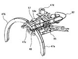
- the spill-off prevention rails 47a and 47b as support members are provided so as to face the inner peripheral surface in the upper part of the vertical ring lottery unit 40. 13).
- the lottery balls 73 conveyed above the vertical ring lottery device 40 can rotate around the vertical ring lottery device 40 by rotational driving while being supported by the spill-off prevention rails 47a and 47b. It has a configuration. Specifically, the conveyance direction rear edge of the opening of the lottery pocket functions as an extruding member and pushes the rear of the lottery ball 73 in the conveyance direction, so that the conveyance direction is controlled by both side edges in the conveyance direction of the opening that functions as a regulating member.
- the lottery balls 73 are conveyed while rolling or sliding on the spill-off preventing rails 47a and 47b while restricting the movement of the lottery balls 73 in a direction (lateral direction) perpendicular to the rails.
- the structure of the inclined ring lottery machine 50 is that the rotation axis thereof is inclined with respect to the vertical direction and the horizontal direction, and the entrance of the lottery pocket 51 is open to the outer peripheral surface side.
- the donut shape is configured to surround the hollow region with a part of the hollow region exposed to the outside as shown in FIGS.
- the configuration is the same as that of the vertical ring lottery device 40 in that it has the main body structure portion. More specifically, a plurality of lottery pockets 51 having an internal space that can accommodate about one lottery ball 73 is formed on the outer peripheral surface of the inclined ring lottery machine 50 in the circumferential direction.
- 20 lottery pockets 51 are provided at equal intervals on the outer peripheral surface of the inclined ring lottery machine 50.
- the inclined ring lottery machine 50 is provided with a partition member 52 for partitioning the lottery pockets 51 from each other on a base 54 fixed to the apparatus support base 60.
- the partition member 52 of the inclined ring lottery device 50 is rotationally driven on the base 54 in the counterclockwise direction in the drawing by a drive device (not shown) provided on the device support base 60. Thereby, the lottery pocket 51 of the inclined ring lottery machine 50 moves around.
- the lottery ball 73 is blocked by the shutter 83a in the ball insertion standby unit 83 and temporarily stored, and the shutter 83a moves as shown in FIG. On the slope 54a.
- the slope 54 a is disposed adjacent to the partition member 52 at a position below the inclined ring lottery device 50, and is formed to be inclined toward the partition member 52.
- the lottery balls 73 on the slope 54a receive a force that moves toward the partition member 52 due to gravity.
- the lottery ball 73 immediately after being thrown has a relatively high moving speed of the partition member 52 with respect to the lottery pocket 51, so that the lottery ball 73 cannot enter the lottery pocket 51 and moves on the slope 54 a along the circumferential direction of the inclined ring lottery machine 50.
- the vertical ring lottery device 40 and the inclined ring lottery device 50 are arranged so that a part of the other lottery device is located in the hollow area of each other. More specifically, in the present embodiment, the lottery units 40 and 50 are arranged so that the two lottery units 40 and 50 are connected to each other in a chain shape.
- the hollow area tends to become a dead space, and the physical lottery apparatus having such a configuration is likely to be enlarged.
- a plurality of dead spaces may exist, so that the physical lottery apparatus is likely to be larger.
- each lottery device 40, 50 is canceled by inserting each other's main body structure portion into the dead space.
- the physical lottery device center lottery device 3
- the physical lottery device is prevented from being unnecessarily increased in size, and the physical structure having a compact structure.
- a lottery apparatus can be realized.
- the vertical ring lottery device 40 and the inclined ring lottery device 50 in this embodiment are both donut-shaped with the loop of the main body structure portion closed, but a part of the loop of the main body structure portion is opened. It may be U-shaped or C-shaped.
- FIG. 11 is a block diagram showing a schematic configuration of a main part of the central control device 30 that controls the center lottery device 3.
- the central controller 30 includes a CPU 31, an input / output port 31a, a ROM 32, a RAM 33, a first rotation control unit 34a, a second rotation control unit 34b, a table drive control unit 35, a display control unit 36, a transport control unit 37, and a first sensor.
- a control unit 38a, a second sensor control unit 38b, and the like are included.
- the input / output port 31a is used for data communication with each station control device 20.
- the ROM 32 stores various programs used by the CPU 31 and data such as various databases, and outputs them to the CPU 31.
- the RAM 33 temporarily stores variable data calculated by the CPU 31, and stores various fluctuation data such as the number of jackpots stored.
- the first rotation control unit 34 a controls the first driving device 61 that rotates the vertical ring lottery device 40 under the control of the CPU 31.
- the second rotation control unit 34 b controls the second driving device 62 that rotates the inclined ring lottery device 50 under the control of the CPU 31.
- the table drive control unit 35 controls the table drive device 63 that rotationally drives the rotary table 64 under the control of the CPU 31.
- the display control unit 36 constitutes a display unit together with the first display device 71 for the vertical ring lottery device 40 and the second display device 72 for the inclined ring lottery device 50.
- the conveyance control unit 37 controls various driving devices such as a conveyance path switching device existing in the ball conveyance device 80 under the control of the CPU 31.
- the first sensor control unit 38a corresponds to a lottery pocket 41 containing a lottery ball 73 in accordance with output signals from a first ball sensor 45 and a first pattern sensor 46, which will be described later, provided in the vertical ring lottery unit 40.
- the winning pocket signal is output to the CPU 31.
- the second sensor control unit 38b corresponds to the lottery pocket 51 containing the lottery balls 73 in accordance with output signals from a second ball sensor 55 and a second pattern sensor 56, which will be described later, provided in the inclined ring lottery machine 50.
- the winning pocket signal is output to the CPU 31.
- FIG. 12 is a perspective view showing the entire configuration of the ball transport device 80 connected to the ball discharge portion provided in each of the vertical ring lottery device 40 and the inclined ring lottery device 50.
- FIG. 13 is a perspective view for explaining the ball transport device 80 and its peripheral configuration.
- FIG. 14 is a side view for explaining the ball transport device 80 and its peripheral configuration.
- the configuration of the ball transport device 80 will be described along the transport path of the lottery balls 73 discharged from the ball discharge unit of the vertical ring lottery device 40.
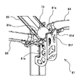
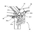
- Rails 47a and 47b are provided. As shown in FIG. 13, the spill-off preventing rails 47a and 47b are divided into two in the circumferential direction, and a gap through which the lottery ball 73 can pass is formed between them. This gap functions as a ball discharge portion (hereinafter referred to as “first ball discharge portion”) 48 of the vertical ring lottery device 40. That is, the lottery balls 73 conveyed by the rotational drive of the vertical ring lottery device 40 fall downward through the first ball discharge unit 48 by their own weight when they reach the position facing the first ball discharge unit 48.
- the first ball discharge unit 48 is provided with a shutter 47c serving as a discharge switching unit that functions as a discharge switching unit that is in a discharge state in which the lottery balls 73 are discharged from the first ball discharge unit 48 or in a non-discharge state in which the lottery balls 73 are not discharged. It has been.
- the shutter 47c is a view in which the driving device 47d controlled by the transport control unit 37 of the central controller 30 opens the first ball discharge unit 48 and the ball passing position shown in FIG. It can move to the ball discharge position shown in FIG. If the lottery balls 73 pass through the first ball discharge unit 48 when the shutter 47c is positioned at the ball passing position as shown in FIG.
- the lottery balls 73 do not fall from the first ball discharge unit 48, and lottery The vertical ring lottery device 40 is moved around one more round while remaining in the pocket 41 for use.
- the lottery balls 73 pass through the first ball discharge unit 48 when the shutter 47c is positioned at the ball discharge position as shown in FIG. 16, the lottery balls 73 fall from the first ball discharge unit 48.
- the lottery balls 73 that have entered the lottery pocket 41 are discharged from the first ball discharge portion 48 or without being discharged. It is possible to selectively execute whether or not the vertical ring lottery device 40 is moved once more by passing 48.
- the upper end portion of the first transfer rail 82 of the ball transfer device 80 is disposed below the first ball discharge portion 48. As shown in FIG. 14, the first transport rail 82 is gently inclined and its lower end is opened. Below the lower end of the first transport rail 82, a ball throwing standby unit 83 is used to transport the lottery balls 73 from the transport path switching device 81 (described later) to the ball throwing standby unit 83 of the inclined ring lottery device 50 by its own weight.
- the 2nd conveyance rail 84 which inclines toward is arrange
- the lottery ball 73 transported on the first transport rail 82 falls from the lower end portion of the first transport rail 82, the lottery ball 73 is received by the second transport rail 84, and the inclined ring lottery machine 50 along the second transport rail 84. To the ball throwing-in waiting section 83.
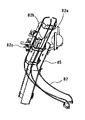
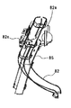
- a drop opening 82 a through which the lottery ball 73 can pass is formed in the middle of the first transport rail 82.
- the drop opening 82a is provided with a shutter 82b that is in a discharge state in which the lottery balls 73 are discharged from the drop opening 82a or in a non-discharge state in which the lottery balls 73 are not discharged.
- the shutter 82b is moved to the closed position shown in FIG. 17 where the drop opening 82a is closed by the driving device 82c controlled by the conveyance control unit 37 of the central control device 30, and the open position shown in FIG. 18 where the drop opening 82a is opened. It is movable.
- the upper end portion of the third transport rail 85 of the ball transport device 80 is disposed below the drop opening 82 a of the first transport rail 82.
- the third transport rail 85 is gently inclined as shown in FIG. 14, and its lower end is connected to the entrance of the transport path switching device 81.
- the lottery balls 73 are supplied to the vertical ring lottery device 40 or the inclined ring lottery device 50 by driving and controlling the transfer path switching device 81 as described later, and the vertical ring lottery device 40 or the inclined ring lottery device 50 is inclined. A physical lottery using the lottery balls 73 can be performed by the ring lottery machine 50.
- the lottery balls 73 to be supplied to the vertical ring lottery device 40 or the inclined ring lottery device 50 are stored in a state where they are aligned with the lower end side portion of the third transport rail 85 connected to the entrance side of the transport path switching device 81. Is done. That is, in the present embodiment, a ball storage section is configured by the lower end side portion of the third transport rail 85 and the transport path switching device 81. Therefore, in this embodiment, by controlling the operation of the shutter 82b, the lottery balls 73 discharged from the first ball discharge unit 48 are sent to the ball insertion standby unit 83 of the inclined ring lottery device 50, or the ball storage unit Can be selectively executed.
- FIG. 1 a notch portion through which the lottery ball 73 can pass is formed on the circumferential movement path of the lottery pocket 51 in the base 54 of the inclined ring lottery machine 50.
- This notch functions as a ball discharge portion (hereinafter referred to as “second ball discharge portion”) 58 of the inclined ring lottery device 50. That is, when the lottery balls 73 conveyed by the rotational drive of the inclined ring lottery device 50 reach the position facing the second ball discharge unit 58, the second ball discharge unit 58 is caused by its own weight as shown in FIG. It is discharged through.
- the second ball discharge unit 58 has a discharge state in which the lottery balls 73 are discharged from the second ball discharge unit 58 or a non-discharge state in which the lottery balls 73 are not discharged.
- a shutter 57 serving as a discharge switching unit that functions as a discharge switching unit is provided. The shutter 57 is driven by a driving device 47d and operates integrally with the shutter 47c of the vertical ring lottery device 40, and closes the second ball discharge portion 58, and the second ball discharge portion 58 shown in FIG. Can be moved to the ball discharge position shown in FIG.
- the lottery balls 73 pass through the second ball discharge unit 58 when the shutter 57 is positioned at the ball passing position as shown in FIG.
- the lottery balls 73 do not fall from the second ball discharge unit 58.
- the inclined ring lottery device 50 is moved around the other round in the lottery pocket 51.
- the lottery balls 73 pass through the second ball discharge portion 58 when the shutter 57 is positioned at the ball discharge position as shown in FIG. 16, the lottery balls 73 fall from the second ball discharge portion 58. .
- the lottery balls 73 that have entered the lottery pocket 51 are discharged from the second ball discharge portion 58 or without being discharged. It is possible to selectively execute whether or not the inclined ring lottery device 50 is moved once more by passing through 58.
- the lottery balls 73 discharged from the second ball discharge portion 58 of the second ball discharge portion 58 are guided to the upper end portion of the above-described third transfer rail 85 of the ball transfer device 80 by the discharge slope 58a. Therefore, the lottery balls 73 discharged from the second ball discharge unit 58 are transferred by the third transfer rail 85 to the entrance of the transfer path switching device 81, that is, the ball storage unit.
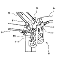
- the conveyance path switching device 81 mainly includes an eccentric rotating member 81a and a drive motor (not shown) that rotates the eccentric rotating member 81a.
- the eccentric rotation member 81a is a disk-shaped member, and a drive motor is connected to a rotation shaft provided at an eccentric position shifted from the center of the disk. The rotation direction and the rotation angle of the drive motor are controlled by the conveyance control unit 37 of the central controller 30.
- the eccentric rotating member 81a stops in a state in which the end portion on the long radius side farthest from the rotation axis of the eccentric rotating member 81a faces directly below in the vertical direction, as shown in FIG.
- the lottery ball 73 located on the most downstream side among the plurality of lottery balls 73 stored side by side at the lower end side portion of the third transport rail 85 connected to the entrance of the transport path switching device 81 is shown in FIG.
- the lottery ball 73 on the most downstream side is positioned above the eccentric rotating member 81a in the vertical direction.
- the transfer path switching device 81 includes a first outlet connected to the upper end portion of the fourth transfer rail 86 inclined toward the ball insertion position of the vertical ring lottery device 40, and a ball insertion standby unit 83 of the inclined ring lottery device 50. There are two outlets, a second outlet connected to the upper end of the second transport rail 84 inclined toward the front. Each bottom surface of these outlets is located at a position higher than the lower position of the lottery ball 73 positioned in the transport path switching device 81 in the standby state.
- the end portion on the long radius side of the eccentric rotating member 81a is rotated upward in the vertical direction. Accordingly, the lottery ball 73 is gradually moved from the lower part of the lottery ball 73 toward the first outlet connected to the upper end of the fourth transport rail 86 from the peripheral portion facing the rotation direction of the eccentric rotation member 81a. Push it up. Then, when the end portion on the long radius side of the eccentric rotating member 81a faces directly above the vertical direction, the lottery ball 73 is lifted to the height of the first outlet by the peripheral edge portion of the eccentric rotating member 81a and the fourth transport rail 86. The lottery balls 73 are pushed to the side and conveyed to the ball insertion position of the vertical ring lottery device 40 through the fourth conveyance rail 86 from the first outlet.
- the configuration and operation for detecting which lottery pocket 41, 51 the lottery ball 73 has entered will be described.
- the configuration and operation related to this detection are substantially the same in both the vertical ring lottery device 40 and the inclined ring lottery device 50. Therefore, in the following description, the inclined ring lottery device 50 is taken as an example. Description of the vertical ring lottery device 40 will be omitted.
- FIG. 22 is a perspective view showing the configuration of the second pattern sensor 56 provided in the inclined ring lottery machine 50.
- the partition member 52 forming the lottery pocket 51 is driven so as to go around.
- the central control device 30 is fixedly arranged inside the device support base 60. Therefore, if a sensor for detecting that a lottery ball 73 has entered each lottery pocket 51 is provided in the partition member 52 so as to move around together with the lottery pocket 51, the output signal of the sensor is stabilized. It is difficult to transmit to the central controller 30. Therefore, in the present embodiment, a configuration is adopted in which only the sensors that are fixedly arranged are used to detect which lottery ball 73 has entered in the orbiting lottery pocket.
- the second ball sensor 55 is fixedly disposed on a portion of the base 54 through which the lottery pocket 51 passes in the lower part of the inclined ring lottery unit 50.
- a total of seven second ball sensors 55 one at the bottom of the circulation path of the lottery pocket 51 and three on both sides in the circumferential direction, They are spaced apart by the same distance.
- Each of the seven second ball sensors 55 is a sensor constituted by a mechanical switch, and a switch piece of the second ball sensor 55 through which a lottery ball 73 entering one of the lottery pockets 51 passes first.
- the lottery balls 73 are detected by the second ball sensor 55 by pushing down with the own weight.
- the second pattern sensor 56 is fixedly disposed on the inner peripheral surface side of the inclined ring lottery device 50 and at a location facing the ball insertion standby portion 83 (a location indicated by symbol A in FIG. 9).
- the second pattern sensor 56 reads the mark pattern of the mark plate 52 a provided on the inner peripheral surface of the partition member 52 so as to be equally spaced from each other by the same number as the lottery pockets 51.
- Each mark plate 52a includes one trigger piece 52b and a maximum of five mark pieces 52c, and different mark patterns are formed depending on the combination of the presence or absence of the mark pieces 52c.
- the second pattern sensor 56 includes five mark sensors 56a for detecting the mark pieces 52c of the mark plate 52a and one trigger sensor 56b for detecting the trigger pieces 52b of the mark plate 52a.
- Each of the mark sensor 56a and the trigger sensor 56b is a transmissive optical sensor, and detects whether or not the optical path is blocked by the mark piece 52c or the trigger piece 52b.
- the second pattern sensor 56 Each time the second pattern sensor 56 detects the trigger piece 52b by the trigger sensor 56b, the second pattern sensor 56 outputs a pattern signal indicating a combination of output signals of the five mark sensors 56a at the time of the detection to the second sensor control unit 38b of the central controller 30. Is output to. Then, it is assumed that the lottery ball 73 enters the lottery pocket 51 and is detected by, for example, the second ball sensor 55 (second ball sensor 55 at the center in the circumferential direction) located at the bottom of the seven second ball sensors 55. . In this case, a ball detection signal is output from the second ball sensor 55, and this ball detection signal is input to the second sensor control unit 38 b of the central controller 30.
- the second sensor control unit 38b Upon receiving this ball detection signal, the second sensor control unit 38b receives the input of the pattern signal from the second pattern sensor 56 at the same time or immediately after the reception of the ball detection signal, so that the lottery pocket 51 corresponding to the pattern signal is displayed.
- the lottery ball 73 is specified as a lottery pocket.
- the positional relationship between the second pattern sensor 56 and the second ball sensor 55 located at the lowermost part is fixed. Specifically, when the lottery pocket 51 containing the lottery ball is located at the position facing the lowermost second ball sensor 55, the lottery pocket 51 is located downstream in the circumferential movement direction of the lottery pocket. The mark pattern of the mark plate 52 a provided on the inner peripheral surface side of the lottery pocket shifted by five is detected by the second pattern sensor 56. Therefore, when the lottery ball 73 is detected by the second ball sensor 55 located at the bottom, the mark pattern of the mark plate 52a detected by the second pattern sensor 56 is a lottery arranged at the position facing the mark plate 52a.
- the lottery pocket 51 corresponds to the lottery pockets that are shifted by five on the upstream side in the circumferential movement direction of the lottery pocket. Therefore, the second sensor control unit 38b that has received the ball detection signal from the lowermost second ball sensor 55 receives the pattern signal from the second pattern sensor 56 at the same time as or immediately after the reception, for example, With reference to the data table indicating the relationship, the lottery pocket containing the lottery ball 73 can be specified. Then, the second sensor control unit 38b outputs a winning pocket signal indicating the specified lottery pocket to the CPU 31.
- the positional relationship between each second ball sensor 55 and the second pattern sensor 56 is different from each other. Therefore, the correspondence between the pattern signal from the second pattern sensor 56 and the lottery pocket containing the lottery ball 73 differs for each second ball sensor 55 that detects the lottery ball 73.
- the mark pattern read by the second pattern sensor 56 when the second ball sensor 55 arranged on the most upstream side in the circumferential movement direction of the lottery pocket detects the lottery ball 73 is the mark plate 52a. This corresponds to the lottery pockets that are shifted by eight on the upstream side in the circumferential movement direction of the lottery pockets with respect to the lottery pockets 51 arranged at the opposite positions.
- the mark pattern read by the second pattern sensor 56 when the second ball sensor 55 disposed on the most downstream side in the circumferential movement direction of the lottery pocket detects the lottery ball 73 is the opposite position of the mark plate 52a. This corresponds to the lottery pockets shifted by two on the upstream side in the circumferential movement direction of the lottery pockets with respect to the lottery pockets 51 arranged in FIG.
- the lottery pocket 51 is specified as early as possible from the time when the lottery ball 73 enters the lottery pocket 51.
- the lottery ball 73 does not necessarily enter the bottom lottery pocket, and any of the lottery pockets in a range of five lottery pockets, two on each side of the bottom lottery pocket. There is a possibility of entering the lottery pocket 51.
- one second ball sensor 55 is provided only in the vicinity of the most downstream side in the circumferential movement direction of the lottery pocket within this range, the lottery pocket containing the lottery ball 73 can be specified.
- the lottery pocket 51 is specified until the lottery pocket 51 moves to the position of the second ball sensor 55. I can't. Therefore, for a while after the lottery ball 73 enters the lottery pocket 51, the lottery pocket 51 cannot be specified, and there is a case where the production is delayed.
- the maximum delay time from when the lottery ball 73 enters the lottery pocket 51 until it is detected can be reduced. Thereby, the lottery pocket 51 can be specified at an early stage from the time when the lottery ball 73 enters the lottery pocket 51, and adverse effects such as a delay in production can be reduced.
- the second sensor control unit 38b that has received the ball detection signal specifies the lottery pocket containing the lottery ball 73 based on the pattern signal received simultaneously with or immediately after the reception.
- the second sensor control unit 38b always stores the latest pattern signal, and the lottery pocket containing the lottery ball 73 based on the latest pattern signal stored when the ball detection signal is received. It is also possible to adopt a method for identifying This method is superior in that the lottery pocket 51 can be identified earlier.
- FIG. 23 is a flowchart showing the flow of one first center lottery.
- the CPU 31 of the central control device 30 as the specific control execution unit functioning as the specific control execution unit receives the first center lottery start request from any one of the station units 2 via the input / output port 31a (S21).
- the CPU 31 registers a station ID for identifying the station unit 2 in the lottery waiting database of the RAM 33 (S22).
- the first center lottery (specific control) for the two players of the station unit 2 is performed.
- the CPU 31 instructs the table drive control unit 35 to direct the front of the vertical ring lottery device 40 to the station unit 2 of the two players performing the first center lottery. Is output. Thereby, the table drive control unit 35 rotates the rotary table 64 so that the front of the vertical ring lottery unit 40 faces the station unit 2. Thereafter, the CPU 31 outputs a command for sending the lottery balls 73 to the ball insertion slot 86a to the transport control unit 37. In response to this command, the conveyance control unit 37 rotates the drive motor 81b of the conveyance path switching device 81 to rotate the eccentric cam 81a as shown in FIG. Thereby, the lottery balls 73 are thrown into the non-pocket region on the inner peripheral surface of the vertical ring lottery device 40 from the ball slot 86a through the fourth transport rail 86 (S23).
- the lottery balls 73 thrown into the non-pocket area reciprocate like a pendulum on the non-pocket area along the circumferential direction of the vertical ring lottery device 40 while being regulated by the projection wall 43a, and the momentum gradually decreases. .
- the lottery balls 73 move to the pocket region side through the gap between the projection walls 43a due to the inclination of the non-pocket region. Thereafter, the lottery ball 73 moved onto the pocket area drifts on the pocket area while receiving a certain external force from the surface of the moving pocket area, and enters the lottery pocket 41 when passing through any one of the lottery pockets 41. It will be.
- the rotation speed of the vertical ring lottery device 40 is always constant, the surface movement speed of the pocket area is also constant, and the external force that the lottery ball 73 receives from the surface of the pocket area is also constant. For this reason, the lottery ball 73 on the pocket area continues to roll on a track that avoids the lottery pocket 41, and the lottery ball 73 may not enter the lottery pocket 41 no matter how long. Therefore, in the present embodiment, a configuration is provided in which an elapsed time after the lottery ball 73 is thrown into the vertical ring lottery device 40 is measured by a timing unit (not shown). Then, the CPU 31 determines whether or not a predetermined time determined in advance has elapsed based on the elapsed time measured by the time measuring unit (S25).
- This specified time can be set arbitrarily.
- the specified time is as long as the lottery ball 73 on the pocket area does not fall into a situation where the lottery ball 73 keeps rolling on a track avoiding the lottery pocket 41 (in a normal case).
- the time period required for the lottery ball to sufficiently enter the lottery pocket 41 is set. Accordingly, in a normal case, the lottery ball 73 enters one of the lottery pockets 41 before the specified time elapses, and a winning pocket signal corresponding to the lottery pocket 41 is output from the first sensor control unit 38a to the CPU 31. (S24).
- the deceleration advance notice process is a process for displaying a countdown video on the first display device 71 and informing the player in advance when the rotation speed of the vertical ring lottery device 40 is decelerated.
- the CPU 31 that has determined that the specified time has elapsed sends a countdown effect command to the display control unit 36.
- the display control unit 36 performs display control for displaying the countdown video on the first display device 71.
- the first rotation control unit 34a performs a process of reducing the rotation speed of the vertical ring lottery device 40 (S27).
- the lottery ball 73 enters one of the lottery pockets 41 and the CPU 31 receives the winning pocket signal. In such a case, the countdown effect is canceled at that time, and the process of decelerating the rotation speed of the vertical ring lottery device 40 (S27) is not performed. In addition, it is assumed that even after the rotational speed of the vertical ring lottery device 40 is decelerated, the lottery ball 73 does not enter the lottery pocket 41, and a situation occurs where the lottery pocket 41 continues to avoid the lottery pocket 41.
- the elapsed time after deceleration is measured by the time measuring unit, and when the elapsed time exceeds a specified time (a period different from the specified time described above), the deceleration is performed.
- a specified time a period different from the specified time described above
- a configuration in which the rotation speed of the vertical ring lottery device 40 is further decelerated or conversely increased after the advance notice processing is performed can be employed.
- the surface movement speed of the pocket area changes, and therefore the external force received by the lottery ball 73 from the moving pocket area surface (rolling surface) is changed. be able to.
- the lottery ball 73 can be removed from the track. As a result, it is possible to prevent a situation in which the lottery ball 73 rolling on the pocket area does not enter the lottery pocket 41 for a long time.
- the CPU 31 stores it in the RAM 33.
- the prize corresponding to the winning pocket signal is determined with reference to the first prize determination table.
- the awards that can be won in the first center lottery are roughly divided into a payout award (dividend payout award) that pays out an amount of credit corresponding to the award to the player, and is executed by the station unit 2.
- the CPU 31 specifies a prize won in the current first center lottery based on the winning pocket signal received from the first sensor control unit 38a and the first prize determination table.
- the CPU 31 controls the first display device 71 and other effect units (such as an illumination unit and a sound output unit) to perform a predetermined effect. Then, the CPU 31 transmits a payout payout command according to the payout rate of the selected payout payout prize from the input / output port 31a to the station control device 20 of the station unit 2 (S29). That is, in the present embodiment, there are a plurality of types of dividend payout prizes with different payout rates in the dividend payout prize. For example, there are a payout award with a payout ratio of 20 times, a payout award with a payout ratio of 30 times, and a payout award with a payout ratio of 50 times, which are assigned to individual lottery pockets 41, respectively. . When the lottery ball 73 enters the lottery pocket 41 for the payout payout prize, a payout payout payout command including the payout rate assigned to the lottery pocket 41 is transmitted to the station control device 20 of the station unit 2. Is done.
- the CPU 21 constituting the payout processing unit 104A satisfies the start condition because the current first center lottery has recorded all the first lottery condition flags, for example. If so, the five bet histories stored in the first bet cumulative amount storage unit 109 corresponding to the first lottery condition flag are read out. Then, a payout process is performed in which the credit amount obtained by multiplying the accumulated value of the bet history by the payout rate included in the current payout payout command is added to the common credit data stored in the common credit data storage unit 105. Thereafter, the CPU 21 resets the five bet histories stored in the first bet cumulative amount storage unit 109.
- the CPU 31 controls the first display device 71 and other effect units (such as an illumination unit and a sound output unit) to perform a predetermined effect. Then, the CPU 31 transmits a free game start command from the input / output port 31a to the station control device 20 of the station unit 2 (S31).
- the CPU 21 of the station control device 20 that has received this free game start command executes a free game program and controls the progress of the free game until a predetermined free game end condition is satisfied.
- the free game of the present embodiment is a slot game that can be played without betting credits, and the content of the slot game may be the same as or different from a normal slot game.
- a bonus game award for starting a bonus game that is a special game may be employed.
- the CPU 31 controls the first display device 71 and other effect units (such as an illumination unit and a sound output unit) to perform a predetermined effect. . And CPU31 transfers to the operation mode which performs a 2nd center lottery (S40).
- FIG. 24 is a flowchart showing the flow of one second center lottery.
- the CPU 31 of the central control device 30 receives a second center lottery start request from any one of the station units 2 via the input / output port 31a, or whether the winning of the second center lottery is determined in the first center lottery
- the CPU 31 performs the second center lottery for the player of the station unit 2.
- the CPU 31 outputs, to the table drive control unit 35, a drive command for directing the front of the inclined ring lottery device 50 to the station unit 2 of the player who performs the second center lottery.
- the table drive control unit 35 rotates the rotary table 64 so that the front side of the inclined ring lottery device 50 faces the station unit 2.
- the CPU 31 outputs a command for sending the lottery balls 73 to the ball throwing standby unit 83 to the transport control unit 37.
- the conveyance control unit 37 performs different operations depending on the satisfied second center lottery start condition. Specifically, when the second center lottery start condition is satisfied by receiving the second center lottery start request from the station unit 2, the drive motor 81b of the transport path switching device 81 is driven to rotate, and the eccentric cam 81a. Is rotated as shown in FIG. As a result, the lottery balls 73 are transported to the ball throwing standby unit 83 through the second transport rail 84 (S42).
- the shutter 47c provided in the first ball discharge unit 48 of the vertical ring lottery unit 40 is satisfied. 16 is moved to the ball discharge position as shown in FIG. 16, and the shutter 82b provided at the drop port 82a of the first transport rail 82 is moved to the closed position as shown in FIG. As a result, the lottery balls 73 that have entered the lottery pocket 41 corresponding to the second center lottery of the first center lottery pass from the first ball discharge unit 48 to the ball insertion standby unit 83 through the first transport rail 82. It is conveyed (S42).
- the CPU 31 outputs a lottery ball 73 insertion instruction to the transport control unit 37.
- the conveyance control unit 37 performs drive control to move the shutter 83a that has blocked the lottery balls 73 by the ball insertion standby unit 83 as shown in FIG.
- the lottery ball 73 that has been blocked by the shutter 83a is thrown onto the slope 54a of the inclined ring lottery device 50 (S43).
- the relative movement speed of the lottery pocket 51 with respect to the slope 54a is also constant.
- the lottery ball 73 may be repelled by the opening edge portion (partition member 52) of the lottery pocket 51 in the same manner. Therefore, in the present embodiment, a configuration is provided in which the elapsed time after the lottery ball 73 is thrown into the inclined ring lottery device 50 is measured by a timing unit (not shown). Then, the CPU 31 determines whether or not a predetermined time determined in advance has elapsed based on the elapsed time measured by the time measuring unit (S45).
- This specified time can be set arbitrarily. In the present embodiment, this specified time is sufficient for the lottery ball to enter the lottery pocket 51 unless the lottery ball 73 on the slope 54a falls into the above situation (normally). It is set to a period that can be secured. Therefore, in the normal case, the lottery ball 73 enters one of the lottery pockets 51 before the specified time elapses, and a winning pocket signal corresponding to the lottery pocket 51 is output from the second sensor control unit 38b to the CPU 31. (S44).
- This deceleration advance notice process is a process for displaying a countdown video on the second display device 72 and notifying the player in advance when the rotational speed of the inclined ring lottery device 50 is decelerated.
- the CPU 31 that has determined that the specified time has elapsed sends a countdown effect command to the display control unit 36.
- the display control unit 36 Upon receiving this countdown effect command, the display control unit 36 performs display control for displaying the countdown video on the second display device 72.
- the second rotation control unit 34b performs a process of reducing the rotation speed of the inclined ring lottery device 50 (S47).
- the lottery ball 73 enters one of the lottery pockets 51, and the CPU 31 receives the winning pocket signal. In such a case, the countdown effect is canceled at that time, and the process of decelerating the rotation speed of the inclined ring lottery machine 50 (S47) is not performed.
- the lottery ball 73 does not enter the lottery pocket 51 even after the rotational speed of the inclined ring lottery machine 50 is decelerated, for example, after decelerating.
- the elapsed time is counted by the timer, and when the elapsed time has passed a specified time (which may be set to a period different from the above-mentioned specified time), the slope ring lottery unit 50 is subjected to the deceleration advance notice processing. It is also possible to adopt a configuration in which the rotational speed of the motor is further decelerated or conversely increased.
- the CPU 31 When the inserted lottery ball 73 enters one of the lottery pockets 51 and receives a winning pocket signal corresponding to the lottery pocket 51 from the second sensor control unit 38b (S44), the CPU 31 is stored in the RAM 33. The award corresponding to the winning pocket signal is determined with reference to the second award determination table. In this embodiment, the awards that can be won in the second center lottery are roughly divided into a payout award (dividend payout award) that pays out an amount of credit corresponding to the award to the player, and is executed by the station unit 2 There is a free game award for starting a free game which is a special game in the slot game. Then, the CPU 31 specifies a prize won in the current second center lottery based on the winning pocket signal received from the second sensor control unit 38b and the second prize determination table.
- the CPU 31 controls the second display device 72 and other effect units (such as an illumination unit and a sound output unit) to perform a predetermined effect. Then, the CPU 31 transmits a payout payout command corresponding to the payout rate of the selected payout payout to the station control device 20 of the station unit 2 from the input / output port 31a (S49). That is, in the present embodiment, the dividend payout awards in the second center lottery include a plurality of types of payout awards with different payout rates, as in the case of the first center lottery. However, it is desirable that the dividend payout rate in the second center lottery is set higher than the highest payout rate in the first center lottery even at the lowest payout rate.
- a payout award with a payout ratio of 100, a payout award with a payout ratio of 500, and a payout award with a payout ratio of 1000 are provided and assigned to individual lottery pockets 41, respectively.
- a payout payout command including the payout rate assigned to the lottery pocket 41 is transmitted to the station control device 20 of the station unit 2. Is done.
- the CPU 21 constituting the payout processing unit 104A satisfies the start condition because the current second center lottery has recorded, for example, all the first lottery condition flags. If so, the five bet histories stored in the first bet cumulative amount storage unit 109 corresponding to the first lottery condition flag are read out. Then, a payout process is performed in which the credit amount obtained by multiplying the accumulated value of the bet history by the payout rate included in the current payout payout command is added to the common credit data stored in the common credit data storage unit 105. Thereafter, the CPU 21 resets the five bet histories stored in the first bet cumulative amount storage unit 109.
- the first bet cumulative amount storage unit 109 and the second bet All bet histories stored in both of the accumulated amount storage units 111 are read out. Then, a payout process is performed in which the credit amount obtained by multiplying the accumulated value of the bet history by the payout rate included in the current payout payout command is added to the common credit data stored in the common credit data storage unit 105. In this case, the CPU 21 does not reset the five bet histories stored in the first bet cumulative amount storage unit 109 and the second bet cumulative amount storage unit 111.
- the CPU 31 controls the second display device 72 and other effect units (such as an illumination unit and a sound output unit) to perform a predetermined effect. Then, the CPU 31 transmits a free game start command from the input / output port 31a to the station control device 20 of the station unit 2 (S50). Upon receiving this free game start command, the CPU 21 of the station control device 20 executes the free game program, and until the predetermined free game end condition is satisfied, as in the case of the free game prize of the first center lottery, Control the progress of the free game.
- a bonus game award for starting a bonus game which may be a special game (may be a game other than a slot game) may be employed.
- the free game executed by winning the free game prize in the second center lottery ends more than the free game executed by winning the free game prize in the first center lottery. It is preferable to set conditions that are advantageous to the player, such as relaxing the conditions.
- FIG. 25 shows a game screen in the single play mode. In the dual play mode, two individual game screens 11j shown in FIG. 25 are displayed. In this game, when the door image displayed on the individual game screen 11j is touched, a process of subtracting one credit from the common credit data is performed, and the type of character corresponding to the door image is selected. The selected characters are sequentially stored in a predetermined selected character storage area. The character image corresponding to the selected character is displayed on the character display unit 11k at the top of the screen.
- the data for the three characters is deleted from the selected character storage area, and the images of the three characters are deleted from the character display unit 11k, Then, 3 which is the number of characters erased is added to the predetermined count value.
- the predetermined count value reaches a specified value, one or more first lottery condition flags or second lottery condition flags are recorded as a clear bonus.
- the center lottery apparatus 3 executes the first center lottery as in the case of the above embodiment.
- the independent games performed in the game units A and B of the station units 2 of the medal game machine 1 of the present embodiment are all the same game (slot game), but a plurality of types of games may be mixed.
- the slot game may be executed in each of the game units A and B of a certain station unit, and the above-described rescue game may be performed in the other station units.
- a slot game may be executed in the game unit A of the station unit 2, and a rescue game may be executed in the game unit B of the station unit 2.
- a medal game machine that controls the progress of a game on condition that a medal (betting object) is received from a player has been described as an example.
- a token other than a medal or money (money) is received.
- the present invention can be similarly applied to a game system installed in a casino or the like that controls the progress of the game according to conditions.
- the credit data used by the players who play in the game units A and B of the same station unit 2 is common credit data.
- individual credit data is used for each. Also good.
- a relationship is created where mutual credit data is increased in cooperation with each other.
- a conventional betting game device such as a medal game machine or a casino game machine that uses credit data as a bet object or a payout object
- each player plays an independent game using individual credit data. Therefore, there is no idea of cooperating with each other to increase common credit data. Therefore, the configuration of the present embodiment in which the common credit data is commonly used by a plurality of players can provide unprecedented game characteristics in the betting game apparatus.
- the effect of being able to provide unprecedented game characteristics in such a betting game device is that the configuration of this embodiment, that is, a plurality of players, is used as long as the common credit data is shared by a plurality of players. It is not limited to a configuration in which a common lottery condition flag is recorded according to the result of each independent game played by each player. That is, each betting object reception unit in a plurality of betting game devices that execute independent games that progress independently from each other using credit data as a betting object or a paying object is stored in the common credit data storage unit as a bet receiving process.
- a process of reducing the credit amount of the common credit data, and each payout processing unit of the plurality of betting game devices increasing the credit amount of the common credit data stored in the common credit data storage unit as the payout process With this configuration, a relationship in which common credit data is increased in cooperation with each other among a plurality of players is born, and an unprecedented game characteristic can be provided in the betting game device.
- the lottery balls 73 are thrown in multiple times while the shutter 47c provided in the first ball discharge portion 48 is moved to the ball passing position as shown in FIG. Since the lottery pocket 41 containing is closed by the lottery ball 73, the subsequent lottery balls will enter any of the remaining lottery pockets 41.
- the lottery ball 73 that is first introduced is a prize other than the second center lottery prize.
- This explanation is for the case of the vertical ring lottery machine 40, but the same applies to the case of the inclined ring lottery machine 50.
- the means realized by software such as a computer program may be realized by hardware such as a circuit and a chip, and the means realized by hardware such as a circuit and a chip are Alternatively, it may be realized by software such as a computer program.
Landscapes
- Physics & Mathematics (AREA)
- General Physics & Mathematics (AREA)
- Slot Machines And Peripheral Devices (AREA)
- Game Rules And Presentations Of Slot Machines (AREA)
Abstract
Description
このゲーム装置においては、特定制御開始条件に関わる特定制御開始条件カウント値が、ゲーム進行制御部により制御されるゲームの進行結果に応じてカウントされる。そして、特定制御開始条件を満たして特定制御が開始された場合には、その特定制御開始条件を満たすための特定制御開始条件カウント値をカウントしたゲームでベットされたベット対象の累積量に応じた量の払出対象が払い出される。これにより、プレイヤーは、例えば、より多くのベット対象をベットしながらゲームをプレイすることで、特定制御により払い出される払出対象の量が多くなり、特定制御によるハイリスクハイリターンを実現できる。また、プレイヤーは、例えば、より少ないベット対象をベットしながらゲームをプレイすることで、特定制御により払い出される払出対象の量が少なくなり、特定制御によるローリスクローリターンを実現できる。このように、本ゲーム装置によれば、特定制御によるハイリスクハイリターンを望むプレイヤーと特定制御によるローリスクローリターンを望むプレイヤーの両者の要望を、単一のゲーム装置で満たすことが可能となる。
そしてさらに、プレイヤーに対して、毎回のゲームにおいてローリスクローリターンとハイリスクハイリターンを組み合わせて、戦略的にベット量を考えさせてゲームをプレイさせることができる。
本ゲーム装置は、いわゆる賭けゲーム装置であるため、特定制御開始条件を満たして開始された抽選で所定の賞に当選したときの払出対象の払出量を、その特定制御開始条件を満たすための特定制御開始条件カウント値をカウントしたゲームでベットされたベット対象の累積量に応じて決める場合、その累積量が異なっていても払出対象の払出率の期待値がほぼ一定となるようにすることが望まれる。ベット対象の累積量によって払出率の期待値に大きな差があると、最も払出率の期待値が高い量でしかベット対象がベットされることがなくなるからである。本ゲーム装置によれば、ベット対象の累積量が異なっていても特定制御による抽選で所定の賞に入賞したときに払い出される払出対象の払出率の期待値が大きく変動することがないようにすることが可能となる。
このゲーム装置においては、コンピュータ抽選よりも、プレイヤーの信頼が得やすい物理抽選で特定制御による抽選を行うことができるので、特定制御による抽選の信頼性を高めることができる。
通常、入賞ライン数が多いとプレイヤーは入賞しやすくなるように感じる。よって、本ゲーム装置によれば、プレイヤーに対し、ベット対象の量が多くすれば特定制御が開始されやすくなり、その特定制御による払出対象の払い出しを受けやすくなると感じさせることができる。よって、より多くのベット対象をプレイヤーにベットしてもらうことが期待できる。
特定制御開始条件に関わる特定制御開始条件カウント値が1種類しか存在しない場合、特定制御開始条件を満たしてその特定制御開始条件カウント値がリセットされると、再び特定制御開始条件を満たすまで最初からその特定制御開始条件カウント値をカウントさせる必要が生じる。そのため、プレイヤーは再び特定制御開始条件を満たすまでにゲームを数多く繰り返す必要があると推測するので、特定制御開始条件を満たしたタイミングでゲームプレイを終えてしまうことが多い。これに対し、このゲーム装置においては、特定制御開始条件カウント値及び第2特定制御開始条件カウント値のいずれか一方について所定の特定制御開始条件が満たされても、他方のカウント値は維持される。これにより、特定制御開始条件を満たしたタイミングでゲームプレイを終えてしまうプレイヤーを引き留めることを期待できる。
なお、各図は本発明の内容を理解でき得る程度に形状、大きさ及び位置関係を概略的に示してあるに過ぎず、従って、本発明は各図で例示された形状、大きさ及び位置関係のみに限定されるものではない。また、各図では、構成の明瞭化のため、断面におけるハッチングの一部が省略されている。さらに、後述において例示する数値は、本発明の好適な例に過ぎず、従って、本発明は例示された数値に限定されるものではない。
本メダルゲーム機1は、抽選手段として機能する抽選部としての物理抽選装置であるセンター抽選装置3を囲うように8つのステーション部2を備えている。本実施形態においては、1つのステーション部2において、互いに独立して進行される2つの独立ゲームが実行可能に構成されており、最大16人のプレイヤーが同時にプレイすることができる。
ステーション部2は、筺体の上部に、表示手段及び操作受付手段として機能する表示部及び操作受付部としてのタッチパネル11と、操作受付手段として機能する操作受付部としての2つのスタートボタン12及びベットモード選択ボタン13と、メダル投入口14などが設けられている。タッチパネル11には、図3に示すように、互いに独立して進行される2つの独立ゲームについてのゲーム画面が横並びで表示され、2人のプレイヤーはそれぞれのゲーム画面の表示を見ながらタッチパネル11や各種ボタン12,13を操作することによりゲームをプレイする。本実施形態では、ステーション部2で実行される2つの独立ゲームがスロットゲーム(図柄合わせ遊技)である場合を例に挙げて説明するが、ステーション部2で実行される独立ゲームの種類はこれに限られない。なお、スロットゲームとは、複数種類のシンボル(図柄)を変動表示させ、その後にその変動表示を停止させたときに停止表示されるシンボルが、又は停止表示された複数シンボルによる組み合わせが、予め決められた賞に対応していると、プレイヤーへ所定の特典が付与されるゲームをいう。
タッチパネル11に表示される2つのゲーム画面には、それぞれ、所定順序で配列する2種以上の複数のシンボルが、3つのシンボル表示域11a~11c,11d~11fそれぞれに表示される。また、タッチパネル11には、このほかに、ゲーム画面下部に、プレイヤーがメダル投入口5aから投入したメダルの枚数に相当するクレジットの量を表示するクレジット表示部などの、ゲームに必要な各種情報を表示する表示部11gも表示される。本実施形態では、後述するように、1つのステーション部2でプレイする2人のプレイヤーは、お互いに共通のクレジットを用いてプレイするので、表示部11gに表示されるクレジット表示部は、1つだけしかない。ただし、各プレイヤーがプレイするスロットゲーム自体はそれぞれ独立して進行する独立ゲームであるため、ベット(BET)量を表示するベット量表示部、入賞時の払出量を表示するクレジット獲得量表示部等は、それぞれ個別に設けられている。
ステーション制御装置20は、CPU21、入出力ポート21a、ROM22、RAM23、乱数発生回路24、表示制御部25、音響制御部26、払戻制御部27などから構成されている。入出力ポート21aは、後述する中央制御装置30との間でデータ通信を行うために利用される。ROM22は、CPU21が利用する各種プログラムや各種データベース等のデータを格納しており、これらをCPU21に出力する。RAM23は、CPU21によって演算された変数データなどを一時的に格納したり、クレジットデータ等の各種変動データを記憶したりする。乱数発生回路24は、所定のタイミングで乱数を発生させてそのデータをCPU21に出力する。表示制御部25は、タッチパネル11とともに表示部を構成し、CPU21の制御の下、ゲーム画面等を表示するタッチパネル11の表示制御を行う。音響制御部26は、CPU21の制御の下、スピーカー15から出力する音声によるアナウンスや演出音等を制御する。払戻制御部27は、CPU21の制御の下、メダルを払い戻すためにメダル払戻装置16を制御する。また、CPU21は、メダル投入口に投入されたメダル枚数をカウントする図示しないメダルカウンターや、LED等の照明を制御する照明制御部などにも接続されている。
本実施形態において、1つのステーション部2には、互いに独立して進行される2つの独立ゲームをそれぞれ実行するゲーム部Aとゲーム部Bとが存在する。これらのゲーム部A,Bは、それぞれの独立ゲームの進行を制御するゲーム進行制御手段として機能するゲーム進行制御部としてのゲーム進行制御部101A,101Bを備えている。これらの2つのゲーム進行制御部101A,101Bは、ゲーム基板等のハードウェアを物理的に異ならせて構成してもよいし、同一のハードウェア上で独立して動作する2つのソフトウェアにより仮想的に構成したものであってもよい。あるいは、同一のハードウェア上で動作する単一のソフトウェアにより仮想的に2つのゲーム進行制御部101A,101Bを構成してもよい。なお、各ゲーム部A,Bの構成は同一のものである。
本実施形態のゲーム進行制御部101A,101Bがそれぞれ進行制御する独立ゲームは、スロットゲームである。具体的には、操作受付部102A,102Bがベット操作を受け付けたときに、ベット受付部103A,103Bがそのベット操作に応じたベット量を共通クレジットデータ記憶部105に記憶されている共通クレジットデータが示すクレジット量から減じることで、スロットゲームを開始する。そして、スロットゲームの結果に応じてクレジットを払い出すことを決定する制御を含むスロットゲームの進行制御を行う。また、本実施形態におけるゲーム進行制御部101A,101Bは、ゲーム進行に応じて、第1抽選条件カウント部108及び第2抽選条件カウント部110に、特定制御開始条件カウント値である複数(本実施形態では5つ)の抽選条件フラグを1つずつ順次カウントさせるようにゲーム進行を制御する。
ベット受付部103A,103Bは、CPU21、ROM22、RAM23等により構成され、対応する操作受付部102A,102Bがベット操作(ベット量操作)が受け付けたとき、そのベット操作に応じたベット量を共通クレジットデータ記憶部105に記憶されている共通クレジットデータが示すクレジット量から減じるベット受付処理を行う。
払出処理部104A,104Bは、CPU21、ROM22、RAM23等により構成され、対応するゲーム進行制御部101A,101Bが制御するゲームの進行結果に従い、対応するベット受付部103A,103Bが受け付けたクレジットの量に応じたクレジットを共通クレジットデータ記憶部105に記憶されている共通クレジットデータが示すクレジット量に加算する払出処理を行う。
共通表示部106は、表示制御部25及びタッチパネル11等により構成され、各ゲーム進行制御部101A,101Bによりそれぞれ制御される各独立ゲームの進行に応じた2つのゲーム画面を表示する。この2つのゲーム画面は、タッチパネル11上の画面領域を左右に2分割し、それぞれの画面領域に表示される。また、後述するモード切換部107により、シングルプレイモードに切り換えられた場合、図6に示すように、いずれか一方のゲーム進行制御部101A,101Bにより制御される独立ゲームの進行に応じた1つのゲーム画面のみ表示する。この場合、このゲーム画面は、タッチパネル11上の画面領域全体に表示される。
ステーション部2でプレイする2人のプレイヤーのいずれかによって図示しないメダルがメダル投入口5aに投入されると、そのメダル等はメダルカウンターによりカウントされる。そして、メダルカウンターは、ステーション制御装置20のCPU21に投入メダルデータを出力する。この投入メダルデータを受け取ったCPU21は、投入メダルデータに相当するクレジット量を共通クレジットデータ記憶部105の共通クレジットデータに加算する処理を行う。なお、予めゲーム施設に預けておいたクレジットをクレジット引出処理を行うことにより引き出して使用する場合には、引き出した分の共通クレジットデータが共通クレジットデータ記憶部105に記憶される。
図8は、センター抽選装置3の斜視図である。
図9は、センター抽選装置3を図8とは別の角度から見たときの斜視図である。
本実施形態のセンター抽選装置3は、主に、第1抽選機構である鉛直リング抽選器40と、第2抽選機構である傾斜リング抽選器50と、これらの抽選器40,50を鉛直方向下側から支持する装置支持台60と、2つのディスプレイ装置71,72と、抽選用転動体としての抽選ボール73を各抽選器40,50へ投入しかつ各抽選器40,50から回収するボール搬送装置80とから構成されている。第1ディスプレイ装置71は、鉛直リング抽選器40の中空領域を通じてプレイヤーが視認できるように配置されており、第2ディスプレイ装置72は、傾斜リング抽選器50の中空領域内にその一部が配置されている。
なお、本実施形態における鉛直リング抽選器40及び傾斜リング抽選器50は、いずれも本体構造部分のループが閉じているドーナツ形状のものであったが、本体構造部分のループの一部が開いたU字形状やC字形状のものとしてもよい。
中央制御装置30は、CPU31、入出力ポート31a、ROM32、RAM33、第1回転制御部34a、第2回転制御部34b、テーブル駆動制御部35、表示制御部36、搬送制御部37、第1センサ制御部38a、第2センサ制御部38bなどから構成されている。入出力ポート31aは、各ステーション制御装置20との間でデータ通信を行うために利用される。ROM32は、CPU31が利用する各種プログラムや各種データベース等のデータを格納しており、これらをCPU31に出力する。RAM33は、CPU31によって演算された変数データなどを一時的に格納したり、ジャックポット貯留枚数等の各種変動データを記憶したりする。第1回転制御部34aは、CPU31の制御の下、鉛直リング抽選器40を回転駆動させる第1駆動装置61を制御する。第2回転制御部34bは、CPU31の制御の下、傾斜リング抽選器50を回転駆動させる第2駆動装置62を制御する。テーブル駆動制御部35は、CPU31の制御の下、回転テーブル64を回転駆動させるテーブル駆動装置63を制御する。表示制御部36は、鉛直リング抽選器40用の第1ディスプレイ装置71と、傾斜リング抽選器50用の第2ディスプレイ装置72とともに表示部を構成し、CPU31の制御の下、抽選の説明や演出用の画面等を表示するこれらのディスプレイ装置71,72の表示制御を行う。搬送制御部37は、CPU31の制御の下、ボール搬送装置80に存在する搬送経路切替装置等の各種駆動装置を制御する。第1センサ制御部38aは、鉛直リング抽選器40に設けられた後述する第1ボールセンサ45及び第1パターンセンサ46からの出力信号に応じて、抽選ボール73が入った抽選用ポケット41に対応する当選ポケット信号をCPU31へ出力する。第2センサ制御部38bは、傾斜リング抽選器50に設けられた後述する第2ボールセンサ55及び第2パターンセンサ56からの出力信号に応じて、抽選ボール73が入った抽選用ポケット51に対応する当選ポケット信号をCPU31へ出力する。
図13は、ボール搬送装置80及びその周辺構成を説明するための斜視図である。
図14は、ボール搬送装置80及びその周辺構成を説明するための側面図である。
本実施形態では、上述したように、鉛直リング抽選器40の上方部分に、抽選用ポケット41に入ったまま周回移動する抽選ボール73が抽選用ポケット41からこぼれ落ちるのを防止するためのこぼれ落ち防止レール47a,47bが設けられている。このこぼれ落ち防止レール47a,47bは、図13に示すように、その周方向に2つに分割されており、その間には抽選ボール73が通過可能な空隙が形成されている。この空隙が鉛直リング抽選器40のボール排出部(以下「第1ボール排出部」という。)48として機能する。すなわち、鉛直リング抽選器40の回転駆動により搬送されてきた抽選ボール73は、この第1ボール排出部48との対向位置に到達すると、自重により第1ボール排出部48を通じて下方へ落下する。
よって、本実施形態では、シャッター82bの動作を制御することで、第1ボール排出部48から排出された抽選ボール73を、傾斜リング抽選器50のボール投入待機部83へ送るか、ボール貯留部へ送るかを、選択的に実行することができる。
本実施形態では、上述したように、傾斜リング抽選器50の基台54における抽選用ポケット51の周回移動経路上に、抽選ボール73が通過可能な切欠部が形成されている。この切欠部が傾斜リング抽選器50のボール排出部(以下「第2ボール排出部」という。)58として機能する。すなわち、傾斜リング抽選器50の回転駆動により搬送されてきた抽選ボール73は、この第2ボール排出部58との対向位置に到達すると、図12に示すように、自重により第2ボール排出部58を通じて排出される。
搬送経路切替装置81は、主に、偏心回転部材81aと、偏心回転部材81aを回転させる図示しない駆動モータとから構成されている。偏心回転部材81aは、円盤状部材で構成されており、その円盤中心からズレた偏心位置に設けられる回転軸に駆動モータが接続されている。駆動モータは、中央制御装置30の搬送制御部37により、その回転方向や回転角が制御される。本実施形態において、偏心回転部材81aは、スタンバイ状態では、図19に示すように、偏心回転部材81aの回転軸から最も離れた長半径側端部が鉛直方向真下を向く状態で停止する。このスタンバイ状態では、搬送経路切替装置81の入口に接続された第3搬送レール85の下端側部分に並んで貯留される複数の抽選ボール73のうち最下流側に位置する抽選ボール73が、図19に示すように搬送経路切替装置81内に入り込む。このとき、最下流側の抽選ボール73は、偏心回転部材81aの鉛直方向上方に位置決めされる。
なお、本実施形態において、この検知に関わる構成及び動作は、鉛直リング抽選器40も傾斜リング抽選器50もほぼ同様の構成であるため、以下の説明では、傾斜リング抽選器50を例に挙げて説明し、鉛直リング抽選器40についての説明は省略する。
本実施形態では、上述したように、抽選用ポケット51を周回移動させるために、その抽選用ポケット51を形成する仕切り部材52が周回移動するように駆動させている。一方で、中央制御装置30は、装置支持台60の内部に固定配置されている。そのため、各抽選用ポケット51に抽選ボール73が入ったことを検知するためのセンサを抽選用ポケット51と一緒に周回移動するように仕切り部材52に設けると、そのセンサの出力信号を安定して中央制御装置30へ伝達することが困難である。
そこで、本実施形態では、固定配置されるセンサだけを用いて、周回移動する抽選用ポケットのいずれに抽選ボール73が入ったかを検知する構成を採用している。
第1に、抽選ボール73が抽選用ポケット51に入った時点からなるべく早い時期にその抽選用ポケット51を特定するためである。すなわち、本実施形態においては、抽選ボール73は必ず最下部の抽選用ポケットに入るとは限らず、最下部の抽選用ポケットの両側2つずつの合計5つの抽選用ポケットの範囲で、いずれかの抽選用ポケット51に入る可能性がある。この場合、この範囲内における抽選用ポケットの周回移動方向最下流側付近にのみ1つの第2ボールセンサ55を設ければ、抽選ボール73が入った抽選用ポケットを特定できる。しかし、この場合、抽選ボール73が入った抽選用ポケット51に入った後、その抽選用ポケット51がその第2ボールセンサ55の位置まで移動してくるまでは、その抽選用ポケット51を特定することができない。したがって、抽選用ポケット51に抽選ボール73が入ってからしばらくの間、その抽選用ポケット51を特定できず、演出が遅れるなどの弊害をもたらす場合がある。これに対し、本実施形態のように複数の第2ボールセンサ55を設けることで、抽選用ポケット51に抽選ボール73が入ってからこれが検知されるまでの最大遅延時間を小さくすることができる。これにより、抽選用ポケット51に抽選ボール73が入った時点から早期にその抽選用ポケット51を特定でき、演出が遅れるなどの弊害を軽減することができる。
第2に、例えば、第2ボールセンサ55が故障したり、抽選ボール73による第2ボールセンサ55のスイッチ片の押し込みが経時変化するなどして検知が不安定になったりした場合でも、ダウンタイムを発生させずに、ゲーム進行(物理抽選)を継続可能とするためである。すなわち、本実施形態のように複数の第2ボールセンサ55を設けることで、抽選用ポケット51に抽選ボール73が入った直後に到達する第2ボールセンサ55でボール検知ができない場合であっても次の第2ボールセンサ55でボール検知が可能となり、ダウンタイムを発生させずに、ゲーム進行(物理抽選)を継続することが可能となる。
図23は、1回の第1センター抽選の流れを示すフローチャートである。
特定制御実行手段として機能する特定制御実行部としての中央制御装置30のCPU31は、入出力ポート31aを介して、いずれかのステーション部2から第1センター抽選開始要求を受信した場合(S21)、CPU31は、RAM33の抽選待ちデータベースに当該ステーション部2を特定するためのステーションIDを登録する(S22)。そして、第1センター抽選開始要求を受信した順番で、順次、そのステーション部2の2人のプレイヤーに対する第1センター抽選(特定制御)を行う。第1センター抽選を開始する場合、まず、CPU31は、テーブル駆動制御部35に対し、第1センター抽選を行う2人のプレイヤーのステーション部2に、鉛直リング抽選器40の正面を向かせる駆動命令を出力する。これにより、テーブル駆動制御部35は、そのステーション部2に鉛直リング抽選器40の正面が向くように、回転テーブル64を回転駆動させる。その後、CPU31は、搬送制御部37に対し、抽選ボール73をボール投入口86aへ送る命令を出力する。搬送制御部37は、この命令を受けて、搬送経路切替装置81の駆動モータ81bを回転駆動させ、偏心カム81aを図20に示したように回転させる。これにより、抽選ボール73は、第4搬送レール86を通ってボール投入口86aから鉛直リング抽選器40の内周面上の非ポケット領域へ投入される(S23)。
また、鉛直リング抽選器40の回転速度を減速した後も、抽選ボール73が抽選用ポケット41に入らず、抽選用ポケット41を避け続ける別の軌道に乗ってしまうような事態が生じることが想定される場合には、例えば、減速してからの経過時間を計時部により計時し、その経過時間が規定時間(上記の規定時間とは異なる期間に設定してもよい。)を経過したら、減速予告報知処理を行った後に鉛直リング抽選器40の回転速度を更に減速させたり、逆に増速させたりするような構成も採用できる。
図24は、1回の第2センター抽選の流れを示すフローチャートである。
中央制御装置30のCPU31は、入出力ポート31aを介していずれかのステーション部2から第2センター抽選開始要求を受信するか、第1センター抽選において第2センター抽選賞の当選が決定するかの第2センター抽選開始条件が満たされた場合(S41)、CPU31は、そのステーション部2のプレイヤーに対する第2センター抽選を行う。第2センター抽選を開始する場合、CPU31は、テーブル駆動制御部35に対し、第2センター抽選を行うプレイヤーのステーション部2に、傾斜リング抽選器50の正面を向かせる駆動命令を出力する。これにより、テーブル駆動制御部35は、そのステーション部2に傾斜リング抽選器50の正面が向くように、回転テーブル64を回転駆動させる。
また、傾斜リング抽選器50の回転速度を減速した後も、抽選ボール73が抽選用ポケット51に入らずに上記のような状況に陥ることが想定される場合には、例えば、減速してからの経過時間を計時部により計時し、その経過時間が規定時間(上記の規定時間とは異なる期間に設定してもよい。)を経過したら、減速予告報知処理を行った後に傾斜リング抽選器50の回転速度を更に減速させたり、逆に増速させたりするような構成も採用できる。
2 ステーション部
3 センター抽選装置
11 タッチパネル
20 ステーション制御装置
30 中央制御装置
101A,101B ゲーム進行制御部
102A,102B 操作受付部
103A,103B ベット受付部
104A,104B 払出処理部
105 共通クレジットデータ記憶部
106 共通表示部
107 モード切換部
108 第1抽選条件カウント部
109 第1ベット累積量記憶部
110 第2抽選条件カウント部
111 第2ベット累積量記憶部
Claims (5)
- プレイヤーの操作を受け付ける操作受付部と、
該操作受付部が受け付けたベット量操作に応じて変更可能な量のベット対象を受け付けるベット受付処理を行うベット対象受付部と、
所定のゲーム進行プログラムを実行することにより、該ベット対象受付部がベット受付処理を行うことをゲーム開始条件として繰り返し行われるゲームの進行を制御するゲーム進行制御部と、
該ゲーム進行制御部が制御するゲームの進行結果に従い、所定量の払出対象をプレイヤーへ払い出す払出処理を行う払出処理部とを備えたゲーム装置において、
上記ゲーム進行制御部が制御するゲームの進行結果に応じて、特定制御開始条件カウント値をカウントするカウント部と、
該カウント部が特定制御開始条件カウント値をカウントしたときのゲームでベットされたベット対象の累積量を記憶するベット累積量記憶部と、
該特定制御開始条件カウント値が所定の特定制御開始条件を満たすことにより特定制御を開始する特定制御実行部と、
上記払出処理部は、該特定制御実行部による特定制御に従い、該ベット累積量記憶部に記憶されているベット対象の累積量に応じた量の払出対象を払い出す払出処理を行うゲーム装置。 - 請求項1のゲーム装置において、
上記特定制御実行部が行う特定制御は、所定の賞へ当選するか否かを決定するための抽選を行う制御であり、
上記払出処理部は、該特定制御実行部による該抽選で該所定の賞へ当選するという結果が出たら、該ベット累積量記憶部に記憶されているベット対象の累積量に応じた量の払出対象を払い出す払出処理を行うゲーム装置。 - 請求項2のゲーム装置において、
上記抽選は、抽選用物体を用いた物理抽選であるゲーム装置。 - 請求項1のゲーム装置において、
上記ゲーム進行制御部は、所定の表示部に複数種類の図柄を変動表示させ、その後にその変動表示を停止させたときに、所定の図柄の組み合わせが入賞ライン上に停止表示すると、その図柄の組み合わせに応じた量の払出対象をプレイヤーへ払い出すスロットゲームの進行を、上記ベット対象受付部が受け付けたベット対象の量が多いほど入賞ラインの数が多くなるように制御するものであり、
上記カウント部は、入賞ライン上に特別な図柄の組み合わせが停止表示するというスロットゲームの進行結果に応じて、特定制御開始条件カウント値をカウントしていくゲーム装置。 - 請求項1のゲーム装置において、
上記ゲーム進行制御部が制御するゲームの進行結果に応じて、第2特定制御開始条件カウント値をカウントする第2カウント部と、
該第2カウント部が第2特定制御開始条件カウント値をカウントしたときのゲームでベットされたベット対象の累積量を記憶する第2ベット累積量記憶部とを有し、
上記特定制御実行部は、上記特定制御開始条件カウント値又は上記第2特定制御開始条件カウント値のいずれかが所定の特定制御開始条件を満たすことにより上記特定制御を開始し、
該特定制御開始条件カウント値が所定の特定制御開始条件を満たした場合には、該第2特定制御開始条件カウント値を維持しつつ、該特定制御開始条件カウント値をリセットする処理を行い、
該第2特定制御開始条件カウント値が所定の特定制御開始条件を満たした場合には、該特定制御開始条件カウント値を維持しつつ、該第2特定制御開始条件カウント値をリセットする処理を行うゲーム装置。
Priority Applications (3)
| Application Number | Priority Date | Filing Date | Title |
|---|---|---|---|
| AU2010216855A AU2010216855A1 (en) | 2009-02-19 | 2010-01-18 | Game device |
| US13/148,529 US20110306406A1 (en) | 2009-02-19 | 2010-01-18 | Game apparatus |
| CN2010800087151A CN102325568A (zh) | 2009-02-19 | 2010-01-18 | 游戏装置 |
Applications Claiming Priority (2)
| Application Number | Priority Date | Filing Date | Title |
|---|---|---|---|
| JP2009-037106 | 2009-02-19 | ||
| JP2009037106A JP5017294B2 (ja) | 2009-02-19 | 2009-02-19 | ゲーム装置 |
Publications (1)
| Publication Number | Publication Date |
|---|---|
| WO2010095481A1 true WO2010095481A1 (ja) | 2010-08-26 |
Family
ID=42633768
Family Applications (1)
| Application Number | Title | Priority Date | Filing Date |
|---|---|---|---|
| PCT/JP2010/050469 Ceased WO2010095481A1 (ja) | 2009-02-19 | 2010-01-18 | ゲーム装置 |
Country Status (6)
| Country | Link |
|---|---|
| US (1) | US20110306406A1 (ja) |
| JP (1) | JP5017294B2 (ja) |
| CN (1) | CN102325568A (ja) |
| AU (1) | AU2010216855A1 (ja) |
| TW (1) | TW201032878A (ja) |
| WO (1) | WO2010095481A1 (ja) |
Cited By (2)
| Publication number | Priority date | Publication date | Assignee | Title |
|---|---|---|---|---|
| US8157636B2 (en) | 2008-05-30 | 2012-04-17 | Konami Digital Entertainment Co., Ltd. | Game system, and game apparatus and management apparatus constituting the same |
| CN112691364A (zh) * | 2020-10-30 | 2021-04-23 | 上海酷量信息技术有限公司 | 一种在直播中利用转盘进行互动的系统和方法 |
Families Citing this family (12)
| Publication number | Priority date | Publication date | Assignee | Title |
|---|---|---|---|---|
| JP2864784B2 (ja) | 1991-04-08 | 1999-03-08 | トヨタ自動車株式会社 | 砂型造形機 |
| GB201117329D0 (en) * | 2011-10-07 | 2011-11-23 | Waterleaf Ltd | Gaming systems, apparatus and method with dual game play |
| JP5994072B2 (ja) * | 2011-12-22 | 2016-09-21 | 株式会社オリンピア | 遊技機 |
| US11024128B2 (en) | 2012-01-16 | 2021-06-01 | Interblock D.D. | Drop element gaming systems, apparatus, methods and games |
| JP6081595B2 (ja) * | 2012-08-31 | 2017-02-15 | コナミゲーミング インコーポレーテッド | ゲームマシン、それに用いる制御方法、およびコンピュータプログラム |
| USD705363S1 (en) | 2013-03-14 | 2014-05-20 | Konami Gaming, Inc. | Game machine |
| USD707301S1 (en) | 2013-03-14 | 2014-06-17 | Konami Gaming, Inc. | Game machine |
| USD707302S1 (en) | 2013-03-14 | 2014-06-17 | Konami Gaming, Inc. | Game machine |
| WO2016194916A1 (ja) * | 2015-06-05 | 2016-12-08 | 旭硝子株式会社 | 車載表示装置 |
| US10140806B2 (en) * | 2016-05-31 | 2018-11-27 | Interblock D.D. | Wide area roulette display system with group arena play |
| JP6437485B2 (ja) * | 2016-06-16 | 2018-12-12 | 株式会社カプコン | 物理抽選ゲーム機 |
| SG11202111203PA (en) * | 2019-04-11 | 2021-11-29 | Marvelous Inc | Image display device and operation control method thereof |
Citations (6)
| Publication number | Priority date | Publication date | Assignee | Title |
|---|---|---|---|---|
| JPH11253608A (ja) * | 1998-03-11 | 1999-09-21 | Nippon Kaidoushiki Tokkyo Kk | スロットマシン |
| JP2002239088A (ja) * | 2001-02-22 | 2002-08-27 | Daito Giken:Kk | 遊技台 |
| JP2007215650A (ja) * | 2006-02-15 | 2007-08-30 | Konami Digital Entertainment:Kk | 抽選装置及びこれを用いた遊技機 |
| JP2008206654A (ja) * | 2007-02-26 | 2008-09-11 | Konami Digital Entertainment:Kk | 記憶情報管理装置、ゲーム媒体預かり装置、ゲーム装置及びゲームシステム |
| JP2008206645A (ja) * | 2007-02-26 | 2008-09-11 | Konami Digital Entertainment:Kk | ゲームシステム |
| JP3147545U (ja) * | 2008-10-21 | 2009-01-08 | 株式会社ポラリス | 電子ルーレットゲーム装置 |
Family Cites Families (9)
| Publication number | Priority date | Publication date | Assignee | Title |
|---|---|---|---|---|
| US8747205B2 (en) * | 2002-02-15 | 2014-06-10 | Wms Gaming Inc. | Gaming machine with block wagering |
| JP2003290423A (ja) * | 2002-04-03 | 2003-10-14 | Abilit Corp | スロットマシンおよびゲーム制御方法 |
| US20070060316A1 (en) * | 2003-04-09 | 2007-03-15 | Stargames Corporation Party Limited | Communal slot system and method for operating same |
| US7578739B2 (en) * | 2003-09-05 | 2009-08-25 | Atronic International Gmbh | Multiple progressive jackpots for a gaming device |
| CA2576506A1 (en) * | 2004-08-03 | 2006-02-16 | Wagerworks, Inc. | Gaming method and device involving progressive wagers |
| US7530896B2 (en) * | 2004-12-01 | 2009-05-12 | Atronic International Gmbh | Gaming device gives player award when jackpot meets a trigger threshold |
| WO2007030632A2 (en) * | 2005-09-06 | 2007-03-15 | Wms Gaming Inc. | Wagering game with group free-spin bonus |
| US8172685B2 (en) * | 2006-03-07 | 2012-05-08 | Wms Gaming Inc. | Wagering game with persistent state of game assets affecting other players |
| JP2008161379A (ja) * | 2006-12-27 | 2008-07-17 | Aruze Corp | 遊技機 |
-
2009
- 2009-02-19 JP JP2009037106A patent/JP5017294B2/ja active Active
-
2010
- 2010-01-18 CN CN2010800087151A patent/CN102325568A/zh active Pending
- 2010-01-18 AU AU2010216855A patent/AU2010216855A1/en not_active Abandoned
- 2010-01-18 WO PCT/JP2010/050469 patent/WO2010095481A1/ja not_active Ceased
- 2010-01-18 US US13/148,529 patent/US20110306406A1/en not_active Abandoned
- 2010-02-04 TW TW099103330A patent/TW201032878A/zh unknown
Patent Citations (6)
| Publication number | Priority date | Publication date | Assignee | Title |
|---|---|---|---|---|
| JPH11253608A (ja) * | 1998-03-11 | 1999-09-21 | Nippon Kaidoushiki Tokkyo Kk | スロットマシン |
| JP2002239088A (ja) * | 2001-02-22 | 2002-08-27 | Daito Giken:Kk | 遊技台 |
| JP2007215650A (ja) * | 2006-02-15 | 2007-08-30 | Konami Digital Entertainment:Kk | 抽選装置及びこれを用いた遊技機 |
| JP2008206654A (ja) * | 2007-02-26 | 2008-09-11 | Konami Digital Entertainment:Kk | 記憶情報管理装置、ゲーム媒体預かり装置、ゲーム装置及びゲームシステム |
| JP2008206645A (ja) * | 2007-02-26 | 2008-09-11 | Konami Digital Entertainment:Kk | ゲームシステム |
| JP3147545U (ja) * | 2008-10-21 | 2009-01-08 | 株式会社ポラリス | 電子ルーレットゲーム装置 |
Cited By (2)
| Publication number | Priority date | Publication date | Assignee | Title |
|---|---|---|---|---|
| US8157636B2 (en) | 2008-05-30 | 2012-04-17 | Konami Digital Entertainment Co., Ltd. | Game system, and game apparatus and management apparatus constituting the same |
| CN112691364A (zh) * | 2020-10-30 | 2021-04-23 | 上海酷量信息技术有限公司 | 一种在直播中利用转盘进行互动的系统和方法 |
Also Published As
| Publication number | Publication date |
|---|---|
| JP5017294B2 (ja) | 2012-09-05 |
| JP2010188014A (ja) | 2010-09-02 |
| AU2010216855A1 (en) | 2011-09-22 |
| CN102325568A (zh) | 2012-01-18 |
| US20110306406A1 (en) | 2011-12-15 |
| TW201032878A (en) | 2010-09-16 |
Similar Documents
| Publication | Publication Date | Title |
|---|---|---|
| JP5049986B2 (ja) | ゲームシステム | |
| JP5017294B2 (ja) | ゲーム装置 | |
| JP4535511B2 (ja) | 物理抽選装置及びこれを備えたゲーム装置 | |
| JP4681036B2 (ja) | 物理抽選装置及びこれを備えたゲーム装置 | |
| JP4681037B2 (ja) | 物理抽選装置及びこれを備えたゲーム装置 | |
| JP4847507B2 (ja) | 物理抽選装置及びこれを備えたゲーム装置 | |
| JP4724741B2 (ja) | 物理抽選装置及びこれを備えたゲーム装置 | |
| JP4728379B2 (ja) | 物理抽選装置及びこれを備えたゲーム装置 | |
| JP4847506B2 (ja) | 搬送路選択装置、物理抽選装置及びゲーム装置 | |
| HK1164199A (en) | Game device | |
| HK1164198A (en) | Game system | |
| HK1160811A (en) | Physical lottery equipment and game equipment equipped lottery equipment |
Legal Events
| Date | Code | Title | Description |
|---|---|---|---|
| WWE | Wipo information: entry into national phase |
Ref document number: 201080008715.1 Country of ref document: CN |
|
| 121 | Ep: the epo has been informed by wipo that ep was designated in this application |
Ref document number: 10743610 Country of ref document: EP Kind code of ref document: A1 |
|
| WWE | Wipo information: entry into national phase |
Ref document number: 13148529 Country of ref document: US |
|
| NENP | Non-entry into the national phase |
Ref country code: DE |
|
| WWE | Wipo information: entry into national phase |
Ref document number: 2010216855 Country of ref document: AU |
|
| ENP | Entry into the national phase |
Ref document number: 2010216855 Country of ref document: AU Date of ref document: 20100118 Kind code of ref document: A |
|
| 122 | Ep: pct application non-entry in european phase |
Ref document number: 10743610 Country of ref document: EP Kind code of ref document: A1 |