WO2010095421A1 - 吐出ヘッドおよび吐出装置 - Google Patents
吐出ヘッドおよび吐出装置 Download PDFInfo
- Publication number
- WO2010095421A1 WO2010095421A1 PCT/JP2010/000956 JP2010000956W WO2010095421A1 WO 2010095421 A1 WO2010095421 A1 WO 2010095421A1 JP 2010000956 W JP2010000956 W JP 2010000956W WO 2010095421 A1 WO2010095421 A1 WO 2010095421A1
- Authority
- WO
- WIPO (PCT)
- Prior art keywords
- wall
- tubular member
- flat
- nozzle opening
- actuator
- Prior art date
Links
Images


Classifications
-
- B—PERFORMING OPERATIONS; TRANSPORTING
- B41—PRINTING; LINING MACHINES; TYPEWRITERS; STAMPS
- B41J—TYPEWRITERS; SELECTIVE PRINTING MECHANISMS, i.e. MECHANISMS PRINTING OTHERWISE THAN FROM A FORME; CORRECTION OF TYPOGRAPHICAL ERRORS
- B41J2/00—Typewriters or selective printing mechanisms characterised by the printing or marking process for which they are designed
- B41J2/005—Typewriters or selective printing mechanisms characterised by the printing or marking process for which they are designed characterised by bringing liquid or particles selectively into contact with a printing material
- B41J2/01—Ink jet
- B41J2/135—Nozzles
- B41J2/14—Structure thereof only for on-demand ink jet heads
- B41J2/14201—Structure of print heads with piezoelectric elements
- B41J2/1429—Structure of print heads with piezoelectric elements of tubular type
-
- B—PERFORMING OPERATIONS; TRANSPORTING
- B41—PRINTING; LINING MACHINES; TYPEWRITERS; STAMPS
- B41J—TYPEWRITERS; SELECTIVE PRINTING MECHANISMS, i.e. MECHANISMS PRINTING OTHERWISE THAN FROM A FORME; CORRECTION OF TYPOGRAPHICAL ERRORS
- B41J2/00—Typewriters or selective printing mechanisms characterised by the printing or marking process for which they are designed
- B41J2/005—Typewriters or selective printing mechanisms characterised by the printing or marking process for which they are designed characterised by bringing liquid or particles selectively into contact with a printing material
- B41J2/01—Ink jet
- B41J2/015—Ink jet characterised by the jet generation process
- B41J2/04—Ink jet characterised by the jet generation process generating single droplets or particles on demand
- B41J2/045—Ink jet characterised by the jet generation process generating single droplets or particles on demand by pressure, e.g. electromechanical transducers
-
- B—PERFORMING OPERATIONS; TRANSPORTING
- B05—SPRAYING OR ATOMISING IN GENERAL; APPLYING FLUENT MATERIALS TO SURFACES, IN GENERAL
- B05B—SPRAYING APPARATUS; ATOMISING APPARATUS; NOZZLES
- B05B17/00—Apparatus for spraying or atomising liquids or other fluent materials, not covered by the preceding groups
- B05B17/04—Apparatus for spraying or atomising liquids or other fluent materials, not covered by the preceding groups operating with special methods
- B05B17/06—Apparatus for spraying or atomising liquids or other fluent materials, not covered by the preceding groups operating with special methods using ultrasonic or other kinds of vibrations
- B05B17/0607—Apparatus for spraying or atomising liquids or other fluent materials, not covered by the preceding groups operating with special methods using ultrasonic or other kinds of vibrations generated by electrical means, e.g. piezoelectric transducers
-
- B—PERFORMING OPERATIONS; TRANSPORTING
- B05—SPRAYING OR ATOMISING IN GENERAL; APPLYING FLUENT MATERIALS TO SURFACES, IN GENERAL
- B05B—SPRAYING APPARATUS; ATOMISING APPARATUS; NOZZLES
- B05B5/00—Electrostatic spraying apparatus; Spraying apparatus with means for charging the spray electrically; Apparatus for spraying liquids or other fluent materials by other electric means
- B05B5/001—Electrostatic spraying apparatus; Spraying apparatus with means for charging the spray electrically; Apparatus for spraying liquids or other fluent materials by other electric means incorporating means for heating or cooling, e.g. the material to be sprayed
-
- B—PERFORMING OPERATIONS; TRANSPORTING
- B05—SPRAYING OR ATOMISING IN GENERAL; APPLYING FLUENT MATERIALS TO SURFACES, IN GENERAL
- B05B—SPRAYING APPARATUS; ATOMISING APPARATUS; NOZZLES
- B05B5/00—Electrostatic spraying apparatus; Spraying apparatus with means for charging the spray electrically; Apparatus for spraying liquids or other fluent materials by other electric means
- B05B5/025—Discharge apparatus, e.g. electrostatic spray guns
- B05B5/053—Arrangements for supplying power, e.g. charging power
- B05B5/0533—Electrodes specially adapted therefor; Arrangements of electrodes
-
- B—PERFORMING OPERATIONS; TRANSPORTING
- B05—SPRAYING OR ATOMISING IN GENERAL; APPLYING FLUENT MATERIALS TO SURFACES, IN GENERAL
- B05C—APPARATUS FOR APPLYING FLUENT MATERIALS TO SURFACES, IN GENERAL
- B05C5/00—Apparatus in which liquid or other fluent material is projected, poured or allowed to flow on to the surface of the work
-
- B—PERFORMING OPERATIONS; TRANSPORTING
- B41—PRINTING; LINING MACHINES; TYPEWRITERS; STAMPS
- B41J—TYPEWRITERS; SELECTIVE PRINTING MECHANISMS, i.e. MECHANISMS PRINTING OTHERWISE THAN FROM A FORME; CORRECTION OF TYPOGRAPHICAL ERRORS
- B41J2/00—Typewriters or selective printing mechanisms characterised by the printing or marking process for which they are designed
- B41J2/005—Typewriters or selective printing mechanisms characterised by the printing or marking process for which they are designed characterised by bringing liquid or particles selectively into contact with a printing material
- B41J2/01—Ink jet
- B41J2/015—Ink jet characterised by the jet generation process
- B41J2/04—Ink jet characterised by the jet generation process generating single droplets or particles on demand
- B41J2/045—Ink jet characterised by the jet generation process generating single droplets or particles on demand by pressure, e.g. electromechanical transducers
- B41J2/055—Devices for absorbing or preventing back-pressure
-
- B—PERFORMING OPERATIONS; TRANSPORTING
- B41—PRINTING; LINING MACHINES; TYPEWRITERS; STAMPS
- B41J—TYPEWRITERS; SELECTIVE PRINTING MECHANISMS, i.e. MECHANISMS PRINTING OTHERWISE THAN FROM A FORME; CORRECTION OF TYPOGRAPHICAL ERRORS
- B41J2/00—Typewriters or selective printing mechanisms characterised by the printing or marking process for which they are designed
- B41J2/005—Typewriters or selective printing mechanisms characterised by the printing or marking process for which they are designed characterised by bringing liquid or particles selectively into contact with a printing material
- B41J2/01—Ink jet
- B41J2/135—Nozzles
- B41J2/14—Structure thereof only for on-demand ink jet heads
- B41J2/14201—Structure of print heads with piezoelectric elements
- B41J2/14233—Structure of print heads with piezoelectric elements of film type, deformed by bending and disposed on a diaphragm
-
- B—PERFORMING OPERATIONS; TRANSPORTING
- B41—PRINTING; LINING MACHINES; TYPEWRITERS; STAMPS
- B41J—TYPEWRITERS; SELECTIVE PRINTING MECHANISMS, i.e. MECHANISMS PRINTING OTHERWISE THAN FROM A FORME; CORRECTION OF TYPOGRAPHICAL ERRORS
- B41J2/00—Typewriters or selective printing mechanisms characterised by the printing or marking process for which they are designed
- B41J2/005—Typewriters or selective printing mechanisms characterised by the printing or marking process for which they are designed characterised by bringing liquid or particles selectively into contact with a printing material
- B41J2/01—Ink jet
- B41J2/17—Ink jet characterised by ink handling
- B41J2/175—Ink supply systems ; Circuit parts therefor
Definitions
- the present invention relates to a discharge head suitable for a device for discharging a liquid, a substance containing liquid and particles, and the like.
- Japanese Patent Application Laid-Open No. 2007-296817 applies a voltage to a pressure generator composed of a laminate of a piezoelectric element using PZT (lead zirconate titanate) and the like, a metal plate, and ceramics.
- a method of generating a liquid and discharging a liquid is described.
- Document 1 uses this method to provide an elongated cylindrical piezoelectric body having a diameter of about 0.1 to 1 mm in the middle from the tank to the discharge port, and this portion functions as a pressure pump to provide droplets.
- a method of discharging the ink is described.
- This is called a Gould type ink jet head, and electrodes are formed on the inner surface and outer surface of a cylindrical piezoelectric body, and lead wires for applying a driving voltage are connected.
- the inner electrode of the cylindrical piezoelectric body is fixed to a hollow pipe that penetrates the piezoelectric element by adhesion.
- the hollow pipe is made of an insulating material such as glass in order to avoid electrical contact with the cylindrical piezoelectric body.
- An ink tube for supplying ink from an ink tank or the like is connected to one end of the hollow pipe and the other end Are formed with ejection openings for ejecting ink droplets.
- ink-jet technology developed as a printing device, it has been studied to eject ink and other things onto printing paper and alternatives.
- an actuator such as a piezo element
- the application range is wide because liquid can be discharged without heating.
- Substances to be ejected are not limited to liquids, but a wide variety of substances such as mixtures of liquids and fine particles (liquid substances), aqueous solutions, solvents, reagents, and substances containing biological (biological) materials such as cells and genes. It is being considered.
- the discharge head is also required to be compatible with a liquid having a low viscosity to a high viscosity, compatible with a high surface tension capable of being discharged even with pure water, and resistant to an acidic liquid or a solvent.
- Tubular members including glass tubes, resin tubes, ceramic tubes, and metal tubes, especially glass tubes, are widely used in experiments using reagents as pipettes, etc., and are suitable for handling a wide variety of solutions. Is. Therefore, a Gould type ink jet head in which a glass tube and a cylindrical piezoelectric body are combined is one of the above-mentioned requirements.
- One aspect of the present invention is a tubular member including a flattened flat portion in which a cross section of a pipe line extends in a first direction, and the flat portion is a flat first member to which an actuator is attached on the outside.
- a tubular member including a wall and shaped to be a cavity whose inner volume varies according to the displacement of the first wall, and a nozzle opening provided at one end of the tubular member, wherein the inner volume of the cavity varies
- a discharge head having a nozzle opening for discharging a liquid substance.
- the discharge head provided with this tubular member can discharge the liquid substance from the nozzle opening by changing the internal volume of the cavity by attaching a flat actuator to the flat first wall. Therefore, it is possible to provide a discharge head in which a portion including a cavity is formed by a tubular member such as a glass tube, which can be driven by a flat-plate actuator instead of a cylindrical actuator. For this reason, the discharge head provided with the tubular member can be easily provided at a low cost by a method such as attaching a plate-like piezoelectric element.
- the cavity where the pressure fluctuates in order to discharge the liquid substance from the nozzle opening is a place where bubbles are likely to be generated. Since this discharge head includes a flattened flat portion in which the cross section of the pipe passage of the tubular member extends in the first direction, the cross section of the flow path of the cavity has few corners or no corners (not square). It can be formed in a flat shape (oval shape) or a shape close thereto. Therefore, it is possible to prevent bubbles and liquid substances from adhering due to bubbles or substances contained in the liquid material, and to prevent the liquid material from being clogged, and an ejection head suitable for ejecting a wide variety of liquid materials. Can provide.
- the nozzle opening of this discharge head is formed by narrowing one end of the tubular member. It can be formed from a single tubular member from the cavity to the nozzle opening, for example, a glass tube, has chemical resistance such as acid resistance, is less susceptible to stagnation and clogging due to bubbles, etc., and is used to discharge a wide variety of liquid substances.
- a suitable discharge head can be provided.
- this discharge head has a part of the opposite side of the nozzle opening restricted to the cavity of the tubular member.
- a pressure change due to variation in the internal volume of the cavity can be transmitted to the nozzle opening more efficiently, and can be formed by a single tubular member up to the cavity including the throttle and further to the nozzle opening. For this reason, stagnation and clogging due to bubbles and the like are less likely to occur, and a discharge head suitable for discharging a wide variety of liquid substances can be provided.
- a typical tubular member of the discharge head is a glass tube, a resin tube, a ceramic tube, or a metal tube. Instead of matching the shape of the actuator to these tubular members, a part of the tubular member is formed into a flat plate-shaped first member. By combining with one actuator, a discharge head having the advantages of a tubular member can be provided at low cost.
- the tubular member can be molded to include a flat second wall facing the first wall.
- the outside of the second wall is a flat plate-like second actuator, and a second actuator that is driven independently of the first actuator attached to the outside of the first wall may be attached.
- the pressure in the nozzle (in the ejection head) can be controlled through the cavity under various conditions.
- a planar heater to the outside of the second wall.
- a heater wound in a coil shape may be provided on at least a part of the outer surface of the tubular member.
- the flat second wall can be used as a place for connecting electrodes. Furthermore, by providing a voltage application electrode connected to the connection electrode and extending to the vicinity of the nozzle opening, in addition to a discharge method using an actuator such as a piezo element, a liquid substance using an electrostatic suction method and / or an electrostatic assist method Can be provided.
- the discharge head can adjust the direction of the nozzle opening by curving the first tube section from the cavity of the tubular member to the nozzle opening, and conversely, the mounting position of the actuator with respect to the direction of the nozzle opening can be adjusted. be changed. Therefore, it is suitable for configuring a head block by combining a plurality of ejection heads.
- One of the different aspects of the present invention is an ejection device having the above-described ejection head, a flat plate-like first actuator attached to the outside of the first wall, and a drive device for driving the first actuator.
- the tubular member includes a flat second wall facing the first wall, and further includes a flat plate-like second actuator attached to the outside of the second wall, and a driving device. May drive the first actuator and the second actuator independently.
- the discharge device may further include a voltage application electrode extending to the vicinity of the nozzle opening and an electrostatic drive device for applying a voltage to the voltage application electrode.
- the tubular member includes a flat second wall facing the first wall, and further includes a connection electrode attached to the outside of the second wall, and an electrode for voltage application. Is connected to the electrode for connection, and the electrostatic drive device preferably applies a voltage to the electrode for connection.
- the discharge device may further include a mounting portion on which a container for storing the liquid material can be mounted, and a supply path for supplying the liquid material from the container mounted on the mounting portion to the tubular member.
- a discharge device suitable for discharging various liquid materials such as water-based or biological liquid materials. Can provide.
- One of the different aspects of the present invention includes a flattened flat portion in which a cross section of the pipe extends in the first direction, and a flat first wall to which an actuator is attached to the outside of the flat portion
- the flat member is a tubular member formed so as to be a cavity whose inner volume varies due to the displacement of the first wall, and a liquid substance is discharged to one end of the tubular member due to the variation of the inner volume of the cavity. It is a tubular member provided with a nozzle opening.
- the nozzle opening is preferably formed by narrowing one end of the tubular member. Further, it is desirable that the tubular member is partially narrowed on the opposite side of the nozzle opening with respect to the cavity.
- FIG. 7 is a diagram illustrating different examples of the ejection head, and a cross-sectional view showing a part of the ejection head extracted in order to show different shapes of the flat portion of the ejection head.
- Sectional drawing which shows the further different example of a discharge head Sectional drawing which shows the further different example of a discharge head.
- the figure which shows the further different example of an ejection head Sectional drawing which shows the further different example of a discharge head.
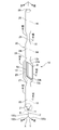
- FIG. 1 shows a schematic configuration of a discharge device according to the first embodiment of the present invention.
- the discharge apparatus 1 includes a discharge head (a head, a nozzle head, a nozzle head driven by an ink jet method) 10 including a glass tube 20 that is a tubular member, and a container 5 that stores a liquid substance 9 discharged from the discharge head 10. And a driving device (driving unit, driver, controller) 2 for driving the first actuator 6 for discharging the liquid substance 9 from the discharge head 10.
- the discharge head 10 has a glass tube (tubular member) 20 extending substantially linearly.
- the front end portion 21 becomes the nozzle opening 11
- the portion (flat portion) 23 that is retracted from the front end portion 21 becomes a flat (flat) cavity (pressure chamber) 13
- the end (rear end) 29 is connected to the container 5 via the supply pipe 4.
- the tubular member 20 having the flat portion 23 can be formed from a single glass tube by an appropriate method, for example, using a mold, and a seamless flow path from the cavity 13 to the nozzle opening 11 is formed inside. ing.
- the portion of the cavity 13 of the glass tube 20 includes the first wall 23a that is flat on the outside.
- the supply tube 4 may be a glass tube, a flexible silicon tube, a resin tube such as a rubber tube, a metal tube, or the like.
- the discharge head 10 includes a plate-like piezoelectric element (piezo element, actuator) 6 attached to an outer surface (outer surface) 23b of the flat first wall 23a of the cavity 13 of the glass tube 20, and includes an actuator (first element). 1), the internal pressure of the cavity 13 is changed, and the liquid substance 9 is discharged from the nozzle opening 11 communicating with the cavity 13.
- the piezoelectric element 6 is attached to the glass tube 20 together with a thin film electrode 6e made of ITO, metal, etc., and expands and contracts by receiving a driving pulse (voltage driving pulse) through the electrode 6e, thereby changing the internal volume of the cavity 13.
- a typical piezoelectric element 6 is a piezo element, and the piezo element 6 has a known configuration including electrodes and the like.
- the driver 2 receives an instruction (signal) from a host device such as a personal computer, and the driver 2 drives the actuator 6 with a drive pulse.
- the actuator 6 displaces the first wall 23a provided with the flat outer surface 23b of the cavity 13 provided in the glass tube 20, and the internal volume of the cavity 13 changes, so that the internal pressure of the cavity 13 changes. Due to the change in the internal pressure, the liquid substance 9 supplied from the container 5 is discharged from the nozzle opening 11 provided at the tip 21 of the glass tube 20.
- the discharge device 1 of this example includes a container 5 attached to the mounting portion 3 of the discharge head 10 and is suitable for discharging and dispensing various liquid substances 9 by the inkjet discharge head 10. Yes.
- the liquid substance 9 is an aqueous solution containing biological samples such as reagents and cells, for example. Since the main part of the ejection head 10 including the cavity 13 is formed by a single glass tube 20, it is a liquid that easily generates bubbles under various conditions, or a liquid substance 9 that easily closes, such as cells. However, it is possible to discharge without causing such a problem. That is, the discharge device 1 can cope with a liquid having a low viscosity to a high viscosity, and can discharge a liquid having a high surface tension such as pure water. Furthermore, since the glass tube 20 is hardly melted, the discharge device 1 can easily discharge an acidic liquid or a solvent.
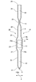
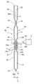
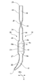
- FIG. 2 shows an enlarged configuration (shape) of the glass tube 20 of the discharge head 10.
- the schematic configuration of the glass tube 20 is shown in a first direction 100x (hereinafter referred to as X direction) orthogonal to the longitudinal direction (central axis) 100z (hereinafter referred to as Z direction), and in the Z direction and X direction.
- the cross section includes a second direction 100y (hereinafter referred to as Y direction) orthogonal to each other.
- the typical size of the glass tube 20 is 1 to 4 mm in outer diameter and 0.05 to 1 mm in thickness, and may be a hard glass tube, a heat-resistant glass tube, a precision glass tube, or the like.
- the outer diameter of the glass tube 20 is more preferably 1 to 3 mm.
- the glass tube 20 includes a front end portion 21 that is gradually narrowed toward the front end nozzle opening 11 from the front end nozzle opening 11 toward the rear end 29, and a first cylindrical portion having a substantially cylindrical cross section behind the front end portion 21. 22 and a first connecting portion 27 for deforming the first cylindrical portion 22 into a flat portion 23 formed in a flat shape in which the cross section is wide in the X direction and narrow in the Y direction.
- a flat portion 23 flattened into a flat shape (oval) or a shape close thereto, a second connecting portion 28 for connecting the flat portion 23 to the second cylindrical portion 24 having a cylindrical cross section behind the flat portion 23, and thereafter
- the narrowed portion 25 is formed by narrowing the cylinder in order to reduce the cross-sectional area, and the third cylindrical portion 26 having a substantially cylindrical cross section for connecting the glass tube 20 to the supply tube 4 at the rear thereof.
- the flat portion 23 may be formed flat in a different direction, for example, in the Y direction and narrow in the X direction.
- the oblate shape is an elongated circle shape excluding a square shape (circular shape) excluding a square shape or a square shape, and excluding a regular circle shape (circular shape).
- the concept includes various shapes such as a shape in which a semicircular shape having a diameter of a distance between opposite sides (interval between opposite sides) is added to each of opposite sides of a rectangle or a square.
- the tip portion 21 of the glass tube 20 is formed into a shape in which the tip of the glass tube 20 is narrowed down to an appropriate size with the nozzle opening 11 as shown in FIG. Yes.
- the typical inner diameter of the nozzle opening 11 is 15 to 200 ⁇ m, and the length of the tip portion 21 tapered toward the tip is, for example, 0.5 to 10 mm. That is, the length of the tip portion 21 is about 1 to 20 times the inner diameter (0.5 to 2.8 mm) of the straight tube portion of the glass tube 20.
- One method of forming the tip portion 21 is to pull the heated glass tube 20, but various methods of known glass processing can be used, and the processing method is not limited.
- the tip portion 21 is desirably provided with a straight portion (straight pipe portion) of about 10 to 500 ⁇ m reaching the nozzle opening 11. Further, the inner diameter of the nozzle opening 11 is more preferably 20 to 200 ⁇ m.
- the first cylindrical portion 22 behind the tip portion 21 is a portion constituting the communication path 12 for communicating the cavity 13 and the nozzle opening 11, and its cross section is shown in an enlarged manner in FIG. 6.
- the length of the first cylindrical portion 22 constituting the communication path 12 is, for example, 1 to 50 mm, and more preferably 1 to 20 mm. That is, the length of the first cylindrical portion 22 is about 2 to 100 times the inner diameter, and more preferably about 2 to 50 times.
- the first cylindrical portion 22 may be a straight pipe or may be bent at an appropriate angle. For example, by bending the first cylindrical portion 22 by 90 degrees, the nozzle opening 11 can be directed in a direction bent by 90 degrees with respect to the longitudinal direction of the glass tube 20, and the liquid substance 9 can be discharged in the direction bent by 90 degrees.
- the flat part 23 behind the first cylindrical part 22 is a part that forms a flat flat cylindrical or long cylindrical space inside and constitutes a cavity 13 that is a pressure chamber.
- the cavity 13 is a place where bubbles are easily generated because the pressure fluctuates in order to discharge the liquid substance 9 from the nozzle opening 11.
- the flat portion 23 is a flat shape (oval shape) in which the cross section of the flow path of the glass tube 20 extends in the first direction (X direction), and the cross section has few or no corners (not square). It is formed in a circle (oval). For this reason, the cross section of the flow path of the cavity 13 can be formed in a smooth shape with little or no step, protrusion, or dent. Therefore, it is possible to prevent bubbles or substances contained in the liquid substance 9 from adhering to the flow of the liquid substance 9 or clogging of the liquid substance 9, and to discharge a wide variety of liquid substances 9.
- a suitable ejection head 10 and ejection apparatus 1 can be provided.
- the typical size of the cavity 13 is such that the maximum height (maximum inner diameter) h in the Y direction is 0.05 to 1.0 mm and the maximum width Wi in the X direction is about 0.5 to 5 mm.
- the length in the longitudinal direction (Z direction) is 2 to 20 mm.
- One method for forming the flat portion 23 is to heat the glass tube 20 and then press it from the vertical direction (direction perpendicular to the longitudinal direction, Y direction). By press-molding the glass tube 20 in a state in which it is expanded not only in the one-dimensional direction (front-rear direction, longitudinal direction, Z direction) but also in the two-dimensional direction (vertical direction, direction orthogonal to the longitudinal direction, Y direction), A flat space 13 is formed inside.
- a flat surface 23 b is formed outside the wall 23 a of the flat portion 23 of the glass tube 20.
- This molding method is an example, and a glass tube 20 having a predetermined shape can be formed by blowing a tubular member such as glass or resin into a mold (mold) as in injection molding.
- a tubular member having a predetermined shape may be obtained.
- the maximum height (maximum inner diameter) h in the Y direction inside the cavity 13 is more preferably 0.05 to 0.5 mm, and the length in the longitudinal direction (Z direction) inside is 2 to 15 mm. More desirable.
- the wall 23a of the flat portion 23, in particular, the wall (first wall) 23a on which the actuator 6 is mounted is plate-like, and the wall thickness t is preferably about 10 to 500 ⁇ m, and more preferably about 10 to 300 ⁇ m.
- the wall thickness t is more preferably about 50 to 500 ⁇ m, and more preferably about 50 to 300 ⁇ m.
- the flat portion 23 is formed so that the maximum external width Wo is about 0.55 to 7 mm, and the width Ws is about 0.5 to 5 mm, more preferably 1.0 to 3.5 mm on the outer surface 23b of the wall 23a. It is desirable to have a substantially flat surface of the order.
- the width Ws of the outer surface 23b of the wall 23a is more preferably about 1.0 to 2.5 mm.
- the wall 23 a By attaching a flat actuator (piezo element) 6 to the flat outer surface 23 b of the wall 23 a of the flat portion 23, the wall 23 a can be vibrated or deformed (displaced) by the actuator 6. Further, by flattening the glass tube 20, the wall 23 a to which the actuator 6 is attached can be made as thin as the above thickness t, and can function as a diaphragm that vibrates or displaces by the actuator 6. By driving the piezoelectric actuator 6 to vibrate the thin wall 23a, the liquid in the communication path 12 can be discharged from the nozzle opening 11 as a droplet.
- the second cylindrical part 24 behind the flat part 23 has a second communication path 14 for communicating (communication) between the cavity 13 and a narrow flow path 15 functioning as an orifice with a narrowed opening area behind the flat part 23. It is a component part.
- the communication path 14 also functions as a buffer for supplying the liquid substance 9 to the cavity 13, and the length of the second cylindrical portion 24 constituting the communication path 14 is, for example, 1 to 50 mm, and more preferably 1 to 20 mm. That is, the length of the second cylindrical portion 24 is about 2 to 100 times the inner diameter, and more preferably about 2 to 50 times.
- the second cylindrical portion 24 may be a straight pipe or may be bent at an appropriate angle.
- the throttle part 25 behind the second cylindrical part 24 is a part for configuring the flow path 15 having a narrow opening area
- FIG. 8 shows a cross section thereof.
- the inner diameter of the flow path 15 is, for example, 15 to 200 ⁇ m, so that the pressure fluctuation of the cavity 13 is efficiently transmitted to the nozzle opening 11 side, and the pressure fluctuation of the cavity 13 is difficult to propagate to the supply pipe 4 and the container 5. It has become.
- One method of forming the narrowed portion 25 is to pull the heated glass tube 20 in the front-rear direction (longitudinal direction), and the length of the tapered portion toward the portion with the smallest opening area is For example, the length is 0.5 to 10 mm, and the entire length of the narrowed portion 25 is about 1 to 20 mm. That is, the length of the tapered portion is about 1 to 20 times the inner diameter (0.5 to 2.8 mm) of the straight tube portion of the glass tube 20, respectively. Further, the inner diameter of the flow path 15 is more preferably 20 to 200 ⁇ m
- the third cylindrical part 26 behind the throttle part 25 is a part constituting the third communication path 16 for communicating with the supply pipe 4.
- a pump connected to the tip of the supply pipe 4 or the like with the nozzle opening 11 placed in the liquid material 9 to be discharged.
- the liquid substance 9 can be discharged toward a target (not shown) such as a substrate.
- the length of the cylindrical portion 26 for sucking and storing the liquid substance 9 is desirably about 5 to 100 mm. It is possible to suck up and discharge a desired amount of the liquid substance 9 without sucking the liquid substance 9 into the supply pipe 4.
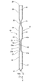
- the first cylindrical portion 22, the flat portion 23, and the second cylindrical portion 24 are formed by processing (forming) one glass tube 20.
- the flat part 23 is formed into a smooth shape via the first cylindrical part 22 and the first connection part 27, and the flat part 23 is further connected via the second cylindrical part 24 and the second connection part 28. Molded into a smooth shape. Therefore, as shown in FIGS. 3 and 4, the cavity 13 having a flat cross section inside the flat portion 23 is connected to the first connecting portion 27 and the first connection portion 27 with respect to the connecting passages 12 and 14 having a cylindrical cross section.
- the flow paths 13a and 13b formed inside the two connecting portions 28 are smoothly connected to each other, so that it is possible to prevent the appearance of minute steps, protrusions, or dents that are likely to occur when different parts are connected. .
- the discharge head 10 using the glass tube 20 can discharge a liquid having a low viscosity to a high viscosity, and can discharge a liquid having a high surface tension such as pure water.
- the end 15 and the middle of one glass tube 20 are squeezed to form a nozzle opening 11 and a flow path 15 serving as a rear orifice. Therefore, the flow path from the orifice 15 to the nozzle opening 11 can be constituted by one of the glass tubes 20, and the entire inner surface of the flow paths having different cross-sectional shapes can be smoothly connected. For this reason, it is possible to prevent the appearance of minute steps, protrusions, or dents that are likely to occur when different parts are connected to the flow path from the rear orifice 15 to the nozzle opening 11 at the tip.
- the capacity of the flat portion 23 constituting the cavity 13 can be easily adjusted by changing the length of the flattened portion 23 of the glass tube 20. Therefore, it is possible to form the cavity 13 having a sufficiently large capacity with respect to the nozzle opening 11, and further, by forming the cavity 13 into a flat space, the outer surface 23 b of the wall 23 a along the cavity 13 is formed.
- the actuator 6 that is sufficiently large with respect to the maximum width Wi and length inside the cavity 13 can be attached (attached). For this reason, by moving the thin wall 23a by the actuator 6 to be expanded or contracted or displaced vertically, the capacity of the cavity 13 can be greatly varied, and the internal pressure of the cavity 13 can be greatly varied. Therefore, it is possible to provide the ejection head 10 and the ejection device 1 that can easily eject various liquid substances 9 from the nozzle openings 11.
- the liquid material 9 is discharged using a seamless glass tube 20, so that a corrosive liquid that can be handled by a glass container or a highly soluble liquid material 9 is safe. Moreover, it can discharge stably. For this reason, the range of the liquid substance 9 that can be ejected is further widened, and it is possible to provide the ejection head 10 and the ejection apparatus 1 that eject the various liquid substances 9 required for various experiments, inspections, and other industrial applications.
- the discharge head 10 since the flat portion 23 is formed in a part of the glass tube 20 to constitute the cavity 13, the internal pressure of the cavity 13 can be varied by the flat piezoelectric actuator 6. Therefore, a seamless discharge head using the glass tube 20 by the piezoelectric actuator 6 such as a flat plate piezoelectric element, which is a general-purpose product and more easily available, without using the cylindrical actuator in accordance with the cylindrical glass tube 20. 10 can be driven. That is, the Gould-type discharge head requires a piezoelectric actuator having a special configuration or shape in accordance with, for example, a glass tube. In this discharge head 10, a part of the glass tube 20 is formed as a general-purpose flat plate. The piezoelectric actuator 6 can be used at a low cost by forming it into a shape that matches the actuator. For this reason, the discharge apparatus 1 which can discharge various liquid substances 9 stably at low cost can be provided.
- FIG. 9 shows a different example of the ejection head 10.
- the flat portion 23 is formed into a shape in which the glass tube 20 is pressed from both sides. As shown in FIG. 9, it is possible to form a flat portion 23 having a shape in which a glass tube 20 is pressed from one side.
- the cavity 13 for obtaining the pressure fluctuation for discharging the liquid substance 9 from the nozzle opening 11 is a place where bubbles are most likely to be generated because the pressure applied to the liquid substance 9 fluctuates, and communication before and after the cavity 13 is included.
- a nozzle opening or the like is configured with another member, or a member that reduces the opening area instead of forming the nozzle opening by narrowing the tip of the glass tube 20 is a glass tube 20. You may attach to the tip of.
- the configuration in which the glass tube 20 is formed into a flat shape and pressurizes the liquid substance 9 is not limited to the discharge head, and a pump in the middle of the path for transporting the liquid substance 9 can also be used.
- the glass tube 20 is used in the above, discharge that can be driven by a flat plate-like piezoelectric actuator is seamless by forming into a similar form using a resin tube, a ceramic tube, and a metal tube instead of the glass tube 20
- the head 10 can be provided.
- the discharge head 10 that discharges the liquid substance 9 from one nozzle opening 11 using one glass tube 20 is shown, but a plurality of nozzle openings 11 may be provided. Further, the number of glass tubes 20 is not limited to one, and may be a discharge head and a discharge device including a plurality of glass tubes.
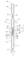
- FIG. 10 is a sectional view showing still another example of the ejection head 10.
- the cavity 13 of the ejection head 10 is formed in a state where the walls on both sides are narrowed, at a position facing (on the opposite side) the first wall 23a of the flat outer surface 23b to which the piezo element 6 is attached.
- a second wall 23c having a flat outer surface 23d on the opposite side is provided.
- the ejection head 10 is driven independently of the piezo element (first piezo element, first actuator) 6 attached to the first wall 23a on the outer surface 23d of the second wall 23c.
- a second piezo element (second actuator) 7 is attached.
- the first piezo element 6 and the second piezo element 7 can be supplied with drive pulses 2p1 and 2p2 having different timing, pulse width, pulse height, and the like from the drive device 2, respectively.
- the cavity 13 can be deformed as if the displacements of the piezoelectric elements 6 and 7 that are deformed (displaced) by the drive pulses 2p1 and 2p2 are synthesized.
- the cavity 13 can be expanded by the piezo element 6 and the cavity 13 can be compressed by the piezo element 7 at different timings, and the liquid substance 9 is discharged by varying the pressure inside the discharge head 10 under various conditions. Can be made.
- a large droplet can be ejected.
- a highly viscous liquid can be discharged by the same method.
- the piezo element When discharging a low-viscosity liquid by using a single piezo element, the piezo element is displaced so as to push out the meniscus after the liquid is drawn from the meniscus by pressure fluctuation caused by the piezo element. Thereafter, if the pressure wave generated inside is reflected in the nozzle and reaches the meniscus after ejection, and the pressure wave is not sufficiently attenuated, there is a possibility of re-ejection.
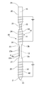
- FIG. 11 is a cross-sectional view showing still another example of the ejection head.
- the cavity 13 of the discharge head 10 is also shaped so that the walls on both sides are narrowed, and is located at a position facing (opposite side) the first wall 23a of the flat outer surface 23b to which the piezo element 6 is attached. And a second wall 23c having a flat outer surface 23d on the opposite side.
- a second piezo element that is driven independently of the piezo element (first piezo element) 6 attached to the first wall 23a on the outer surface 23d of the second wall 23c. 7 is attached to the first piezo element 6 so as not to face the Y direction.
- the first piezo element 6 and the second piezo element 7 can be supplied with drive pulses 2p1 and 2p2 having different timing, pulse width, pulse height, and the like from the drive device 2, respectively.
- the drive pulses 2p1 and 2p2 having different timings are supplied, or the time during which the piezo elements 6 and 7 are deformed (displaced) by the drive pulses 2p1 and 2p2 is changed to be held inside the ejection head 10.
- a traveling wave propagating from the cavity 13 toward the nozzle opening 11 can be created using the liquid substance 9 as a medium. Therefore, the traveling wave can easily move the liquid substance 9 including a biological sample such as a cell that is easily blocked inside the glass tube 20 toward the nozzle opening 11. For this reason, in the discharge head 10, it is possible to further prevent cells and the like from adhering and the flow of the liquid material 9 from being delayed or clogging the liquid material 9.
- the first piezo element 6 and the second piezo element 7 may be attached to either the first wall 23a or the second wall 23c while shifting the position in the longitudinal direction (Z direction).
- FIG. 12 shows still another example of the ejection head.
- an electric heater 60 is wound around the outer surface of the glass tube 20 in a coil shape so that the liquid substance 9 inside the glass tube 20 can be heated.
- the discharge head 10 can discharge the liquid material 9 that is preferably heated to a predetermined temperature or heated and dispensed.
- FIG. 13 shows still another example of the ejection head.
- an electric heater 61 is attached to the outer surface 23 d of the second wall 23 c of the flat portion 23 of the glass tube 20. Since the outer surface 23d of the second wall 23c is flat, the planar heater 61 can be attached, and the liquid material 9 inside the glass tube 20 can be heated at a low cost.
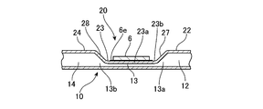
- FIG. 14 shows still another example of the ejection head.
- an electrode 71 for connection is provided on the outer surface 23 d of the second wall 23 c of the flat portion 23 of the glass tube 20.
- a voltage applying electrode 72 is provided on the outside of the glass tube 20 from the connection electrode 71 of the flat portion 23 toward the opening 11 of the tip 21.
- the connection electrode 71 is connected to an electrostatic drive controller (device) 75 so that a pulsed potential for electrostatic suction or electrostatic assist can be applied in the vicinity of the nozzle opening 11.
- a target not shown
- the liquid material 9 can be discharged from the nozzle opening 11 using an electrostatic force.
- the electrostatic drive controller 75 can operate in cooperation with the piezo drive controller 2. For example, after moving the meniscus of the liquid substance 9 to the nozzle opening 11 by the piezo element 6, the liquid substance 9 can be discharged by an electrostatic suction method by applying an electric potential by the electrostatic drive controller 75.
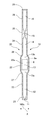
- FIG. 15 shows still another example of the ejection head.
- the nozzle tip 21 and the narrowed portion 25 that forms the narrow flow path 15 are formed by thickening the glass tube 20. Therefore, in this discharge head 10, the part where stress such as constriction tends to concentrate on the glass tube 20 can be reduced, and breakage can be suppressed.
- the rear end 29 is chamfered in a tapered shape, and has a shape in which a step is unlikely to occur when the supply pipe 4 is connected. Therefore, in the discharge head 10 including the connection portion of the supply pipe 4, the generation of bubbles can be suppressed and the clogging of the liquid substance 9 can be suppressed.
- FIG. 16 shows still another example of the ejection head.
- the cylindrical portion 22 that connects the nozzle tip 21 and the flat portion 23 is bent in a 45 ° direction so that the nozzle opening 11 faces in a direction that is approximately 45 ° different from the direction of the central axis of the glass tube 20. ing. Therefore, the liquid substance 9 can be discharged in different directions from the central axis of the discharge head 10.
- the cylindrical portion 22 can be bent at an arbitrary angle as long as there is no problem with the strength of the glass tube 20 and the pressure loss caused by bending the connecting path 12, and the nozzle opening 11 can be directed in an arbitrary direction.
- FIG. 17 shows an example of a head block 80 provided with a plurality of ejection heads 10.
- the head block 80 includes a nozzle tube fixture 81 for fixing the tips 21 of the plurality of ejection heads 10 at predetermined positions or arrangements.
- Each of the plurality of ejection heads 10 has a cylindrical portion 22 bent at an appropriate angle so that the plurality of nozzle openings 11 can be arranged in a small area.
- the piezo elements 6 of the respective discharge heads 10 are arranged in a distributed manner, wiring and the like are easy, and it is shown that a multi-nozzle type discharge head can be constituted by the discharge head 10 using the glass tube 20.
- the plurality of nozzle openings 11 are not limited to a plate-like fixture, and the tip portion 21 of the glass tube 20 may be joined by a joining member or fixed by an adhesive.
- an object to which the liquid substance 9 is discharged by the discharge head 10 for example, a pellet, a test tube, a test recording paper, and a mechanism for moving the discharge head 10 or the object are not shown.
- a discharge device including a mechanism known to those skilled in the art is also included in the scope of the present invention.
Landscapes
- Coating Apparatus (AREA)
- Nozzles (AREA)
- Particle Formation And Scattering Control In Inkjet Printers (AREA)
Abstract
Description
Claims (20)
- 管路の断面が第1の方向に延びた扁円状の扁平部を含む管状部材であって、前記扁平部が、外側にアクチュエータを取り付けられる平坦な第1の壁を含み、前記第1の壁の変位により内容積が変動するキャビティとなるように成形された管状部材と、
前記管状部材の一方の端に設けられたノズル開口であって、前記キャビティの内容積の変動により液状物質を吐出するノズル開口とを有する、吐出ヘッド。 - 請求項1において、
前記ノズル開口は、前記管状部材の前記一方の端が絞られて成形されている、吐出ヘッド。 - 請求項1において、
前記管状部材の前記キャビティに対して前記ノズル開口の反対側の一部が絞られている、吐出ヘッド。 - 請求項1において、
前記管状部材は、ガラス管、樹脂管、セラミックス管または金属管である、吐出ヘッド。 - 請求項1において、
前記第1の壁の外側に取り付けられた平板状の第1のアクチュエータをさらに有する、吐出ヘッド。 - 請求項5において、
前記管状部材は、前記第1の壁に対向した平坦な第2の壁を含み、
前記第2の壁の外側に取り付けられた平板状の第2のアクチュエータであって、前記第1のアクチュエータと独立して駆動される第2のアクチュエータをさらに有する、吐出ヘッド。 - 請求項6において、
前記管状部材は、前記第1の壁に対向した平坦な第2の壁を含み、
前記第2の壁の外側に取り付けられた面状のヒーターをさらに有する、吐出ヘッド。 - 請求項5において、
前記管状部材の外面の少なくとも一部にコイル状に巻かれたヒーターをさらに有する、吐出ヘッド。 - 請求項5において、
前記管状部材は、前記第1の壁に対向した平坦な第2の壁を含み、
前記第2の壁の外側に取り付けられた接続用の電極と、
前記接続用の電極と繋がり前記ノズル開口の近傍まで延びた電圧印加用の電極とをさらに有する、吐出ヘッド。 - 請求項5において、
前記管状部材の前記キャビティから前記ノズル開口に至る第1の管部が湾曲している、吐出ヘッド。 - 請求項5に記載の吐出ヘッドを複数有するヘッドブロック。
- 請求項11において、
当該ヘッドブロックに含まれる複数の吐出ヘッドの少なくともいずれかの吐出ヘッドの前記管状部材の前記キャビティから前記ノズル開口に至る第1の管部が湾曲している、ヘッドブロック。 - 請求項1に記載の吐出ヘッドと、
前記第1の壁の外側に取り付けられた平板状の第1のアクチュエータと、
前記第1のアクチュエータを駆動させる駆動装置とを有する、吐出装置。 - 請求項13において、
前記管状部材は、前記第1の壁に対向した平坦な第2の壁を含み、
さらに、前記第2の壁の外側に取り付けられた平板状の第2のアクチュエータを有し、
前記駆動装置は、前記第1のアクチュエータおよび前記第2のアクチュエータを独立して駆動させる、吐出装置。 - 請求項13において、
前記ノズル開口の近傍まで延びた電圧印加用の電極と、
前記電圧印加用の電極に電圧を印加する静電駆動装置とをさらに有する、吐出装置。 - 請求項15において、
前記管状部材は、前記第1の壁に対向した平坦な第2の壁を含み、
さらに、前記第2の壁の外側に取り付けられた接続用の電極を有し、
前記電圧印加用の電極は、前記接続用の電極と繋がり、
前記静電駆動装置は、前記接続用の電極に電圧を印加する、吐出装置。 - 請求項13において、
液状物質を貯蔵する容器を装着可能な装着部と、
前記装着部に装着された前記容器から液状物質を前記管状部材に供給する供給路とをさらに有する、吐出装置。 - 管路の断面が第1の方向に延びた扁円状の扁平部と、前記扁平部の外側にアクチュエータを取り付けられる平坦な第1の壁とを含み、前記扁平部が、前記第1の壁の変位により内容積が変動するキャビティとなるように成形された管状部材であって、
当該管状部材の一方の端に、前記キャビティの内容積の変動により液状物質を吐出するノズル開口が設けられている、管状部材。 - 請求項18において、
前記ノズル開口は、当該管状部材の前記一方の端が絞られて成形されている、管状部材。 - 請求項18において、
前記キャビティに対して前記ノズル開口の反対側の一部が絞られている、管状部材。
Priority Applications (5)
| Application Number | Priority Date | Filing Date | Title |
|---|---|---|---|
| JP2011500506A JP5504508B2 (ja) | 2009-02-17 | 2010-02-16 | 吐出ヘッドおよび吐出装置 |
| CN201080003917.7A CN102271921B (zh) | 2009-02-17 | 2010-02-16 | 喷出头及喷出装置 |
| SG2011051042A SG172987A1 (en) | 2009-02-17 | 2010-02-16 | Discharge head and discharge device |
| US13/144,536 US8794742B2 (en) | 2009-02-17 | 2010-02-16 | Discharge head and discharge apparatus |
| EP10743551.3A EP2399747B1 (en) | 2009-02-17 | 2010-02-16 | Discharge head and discharge device |
Applications Claiming Priority (2)
| Application Number | Priority Date | Filing Date | Title |
|---|---|---|---|
| JP2009034290 | 2009-02-17 | ||
| JP2009-034290 | 2009-02-17 |
Publications (1)
| Publication Number | Publication Date |
|---|---|
| WO2010095421A1 true WO2010095421A1 (ja) | 2010-08-26 |
Family
ID=42633709
Family Applications (1)
| Application Number | Title | Priority Date | Filing Date |
|---|---|---|---|
| PCT/JP2010/000956 WO2010095421A1 (ja) | 2009-02-17 | 2010-02-16 | 吐出ヘッドおよび吐出装置 |
Country Status (7)
| Country | Link |
|---|---|
| US (1) | US8794742B2 (ja) |
| EP (1) | EP2399747B1 (ja) |
| JP (1) | JP5504508B2 (ja) |
| KR (1) | KR101623807B1 (ja) |
| CN (1) | CN102271921B (ja) |
| SG (1) | SG172987A1 (ja) |
| WO (1) | WO2010095421A1 (ja) |
Cited By (3)
| Publication number | Priority date | Publication date | Assignee | Title |
|---|---|---|---|---|
| KR101836375B1 (ko) | 2010-02-09 | 2018-03-08 | 가부시키가이샤 마이크로제트 | 입상체를 포함하는 액상체의 토출장치 |
| JP2018047429A (ja) * | 2016-09-23 | 2018-03-29 | 東芝テック株式会社 | 液滴噴射装置 |
| JP7367370B2 (ja) | 2019-07-31 | 2023-10-24 | セイコーエプソン株式会社 | 液体噴射装置および液体噴射装置の制御方法 |
Families Citing this family (1)
| Publication number | Priority date | Publication date | Assignee | Title |
|---|---|---|---|---|
| US20200086640A1 (en) * | 2016-10-13 | 2020-03-19 | Panasonic Intellectual Property Management Co., Ltd. | Liquid discharge device, inspection device having liquid discharge device, and cell culture device having liquid discharge device |
Citations (8)
| Publication number | Priority date | Publication date | Assignee | Title |
|---|---|---|---|---|
| JPS57193374A (en) * | 1981-05-07 | 1982-11-27 | Philips Nv | Manufacture of jet-nozzle-duct |
| JPS60180849A (ja) * | 1984-02-29 | 1985-09-14 | Nec Corp | インクジエツトプリントヘツド |
| JPS6125849A (ja) * | 1984-07-17 | 1986-02-04 | Canon Inc | インクジエツト記録装置 |
| JPS62199451A (ja) * | 1986-02-27 | 1987-09-03 | Toshiba Corp | インクジエツト式記録装置 |
| JPS6353049A (ja) * | 1986-08-22 | 1988-03-07 | Hitachi Ltd | 液体噴射式記録ヘツド |
| JPH01285355A (ja) * | 1988-05-13 | 1989-11-16 | Canon Inc | インクジェット記録装置 |
| JPH0564885A (ja) * | 1991-09-09 | 1993-03-19 | Marktec Corp | インクジエツトノズル加振装置 |
| JP2001277520A (ja) * | 2000-03-31 | 2001-10-09 | Seiko Instruments Inc | 記録ヘッド並びに該記録ヘッドを用いた画像記録装置 |
Family Cites Families (5)
| Publication number | Priority date | Publication date | Assignee | Title |
|---|---|---|---|---|
| JPH04251750A (ja) | 1991-01-28 | 1992-09-08 | Fuji Electric Co Ltd | インクジェット記録ヘッド |
| US6367925B1 (en) | 2000-02-28 | 2002-04-09 | Microfab Technologies, Inc. | Flat-sided fluid dispensing device |
| JP2002022614A (ja) | 2000-07-03 | 2002-01-23 | Watanabe Denki Kogyo Kk | 自動車用ヘッドライトのすれ違い灯測定装置 |
| CN101415567B (zh) * | 2006-04-04 | 2011-06-15 | 皇家飞利浦电子股份有限公司 | 书写工具及其书写方法、计算机装置 |
| JP2007296817A (ja) | 2006-05-08 | 2007-11-15 | Canon Inc | 液体吐出ヘッド |
-
2010
- 2010-02-16 SG SG2011051042A patent/SG172987A1/en unknown
- 2010-02-16 EP EP10743551.3A patent/EP2399747B1/en active Active
- 2010-02-16 JP JP2011500506A patent/JP5504508B2/ja active Active
- 2010-02-16 KR KR1020117015095A patent/KR101623807B1/ko active IP Right Grant
- 2010-02-16 CN CN201080003917.7A patent/CN102271921B/zh active Active
- 2010-02-16 US US13/144,536 patent/US8794742B2/en active Active
- 2010-02-16 WO PCT/JP2010/000956 patent/WO2010095421A1/ja active Application Filing
Patent Citations (8)
| Publication number | Priority date | Publication date | Assignee | Title |
|---|---|---|---|---|
| JPS57193374A (en) * | 1981-05-07 | 1982-11-27 | Philips Nv | Manufacture of jet-nozzle-duct |
| JPS60180849A (ja) * | 1984-02-29 | 1985-09-14 | Nec Corp | インクジエツトプリントヘツド |
| JPS6125849A (ja) * | 1984-07-17 | 1986-02-04 | Canon Inc | インクジエツト記録装置 |
| JPS62199451A (ja) * | 1986-02-27 | 1987-09-03 | Toshiba Corp | インクジエツト式記録装置 |
| JPS6353049A (ja) * | 1986-08-22 | 1988-03-07 | Hitachi Ltd | 液体噴射式記録ヘツド |
| JPH01285355A (ja) * | 1988-05-13 | 1989-11-16 | Canon Inc | インクジェット記録装置 |
| JPH0564885A (ja) * | 1991-09-09 | 1993-03-19 | Marktec Corp | インクジエツトノズル加振装置 |
| JP2001277520A (ja) * | 2000-03-31 | 2001-10-09 | Seiko Instruments Inc | 記録ヘッド並びに該記録ヘッドを用いた画像記録装置 |
Cited By (3)
| Publication number | Priority date | Publication date | Assignee | Title |
|---|---|---|---|---|
| KR101836375B1 (ko) | 2010-02-09 | 2018-03-08 | 가부시키가이샤 마이크로제트 | 입상체를 포함하는 액상체의 토출장치 |
| JP2018047429A (ja) * | 2016-09-23 | 2018-03-29 | 東芝テック株式会社 | 液滴噴射装置 |
| JP7367370B2 (ja) | 2019-07-31 | 2023-10-24 | セイコーエプソン株式会社 | 液体噴射装置および液体噴射装置の制御方法 |
Also Published As
| Publication number | Publication date |
|---|---|
| EP2399747A1 (en) | 2011-12-28 |
| JP5504508B2 (ja) | 2014-05-28 |
| KR101623807B1 (ko) | 2016-05-24 |
| EP2399747A4 (en) | 2013-06-26 |
| EP2399747B1 (en) | 2014-08-27 |
| SG172987A1 (en) | 2011-08-29 |
| US8794742B2 (en) | 2014-08-05 |
| KR20110126587A (ko) | 2011-11-23 |
| JPWO2010095421A1 (ja) | 2012-08-23 |
| CN102271921B (zh) | 2014-04-16 |
| CN102271921A (zh) | 2011-12-07 |
| US20110298864A1 (en) | 2011-12-08 |
Similar Documents
| Publication | Publication Date | Title |
|---|---|---|
| EP2613889B1 (en) | A liquid droplet dispenser | |
| EP2371545B1 (en) | Jetting device with reduced crosstalk | |
| JP6301470B2 (ja) | 液滴吐出のためのメニスカス制御を有するマルチパルス波形を提供する方法、装置及びシステム | |
| KR101603807B1 (ko) | 펌핑 챔버 내의 압력을 완충하여 가변적인 드롭 크기 분사를 제공하기 위한 방법 및 장치 | |
| WO2017130695A1 (ja) | インクジェット駆動装置およびインクジェット駆動方法 | |
| JP5504508B2 (ja) | 吐出ヘッドおよび吐出装置 | |
| CN107107614B (zh) | 液滴排出头的驱动方法及液滴排出装置 | |
| JP6650588B2 (ja) | 液体吐出装置と液体吐出装置を有する検査装置、液体吐出装置を有する細胞培養装置 | |
| US20060176341A1 (en) | Device for dispensing drops of a liquid | |
| US6422684B1 (en) | Resonant cavity droplet ejector with localized ultrasonic excitation and method of making same | |
| CN111267490B (zh) | 喷墨头、喷墨涂敷装置以及喷墨涂敷方法 | |
| CN109689373B (zh) | 液滴排出头和液滴排出装置 | |
| KR102330135B1 (ko) | 노즐 영역이 고점도 재료로 재충전되도록 구성되는 프린트헤드 | |
| JP2011098560A (ja) | インクジェットヘッド | |
| WO2019116929A1 (ja) | 液体吐出装置と液体吐出装置を有するセンサ製造装置、液体吐出装置を有する細胞培養装置 | |
| KR20210145239A (ko) | 음향영동 인쇄를 위한 서브파장 공진기 | |
| JP2014184682A (ja) | 液体噴射装置の制御方法および液体噴射装置の制御装置 | |
| JP5266456B2 (ja) | 吐出ヘッド | |
| US20230150262A1 (en) | Efficient Ink Jet Printing | |
| JP2012213957A (ja) | 液体噴射ヘッド及びその製造方法 | |
| US20020127014A1 (en) | Fluid dispensing method and apparatus employing piezoelectric transducer | |
| JP4967609B2 (ja) | 液滴吐出ヘッドの駆動方法 | |
| JP2013006333A (ja) | 液体噴射装置 | |
| JP2010030218A (ja) | ヘッドおよび吐出装置 | |
| JP2002361859A (ja) | インクジェットヘッド |
Legal Events
| Date | Code | Title | Description |
|---|---|---|---|
| WWE | Wipo information: entry into national phase |
Ref document number: 201080003917.7 Country of ref document: CN |
|
| 121 | Ep: the epo has been informed by wipo that ep was designated in this application |
Ref document number: 10743551 Country of ref document: EP Kind code of ref document: A1 |
|
| ENP | Entry into the national phase |
Ref document number: 2011500506 Country of ref document: JP Kind code of ref document: A |
|
| ENP | Entry into the national phase |
Ref document number: 20117015095 Country of ref document: KR Kind code of ref document: A |
|
| WWE | Wipo information: entry into national phase |
Ref document number: 2010743551 Country of ref document: EP |
|
| WWE | Wipo information: entry into national phase |
Ref document number: 13144536 Country of ref document: US |
|
| NENP | Non-entry into the national phase |
Ref country code: DE |