WO2010092978A2 - フィルムラベル缶 - Google Patents
フィルムラベル缶 Download PDFInfo
- Publication number
- WO2010092978A2 WO2010092978A2 PCT/JP2010/051959 JP2010051959W WO2010092978A2 WO 2010092978 A2 WO2010092978 A2 WO 2010092978A2 JP 2010051959 W JP2010051959 W JP 2010051959W WO 2010092978 A2 WO2010092978 A2 WO 2010092978A2
- Authority
- WO
- WIPO (PCT)
- Prior art keywords
- neck
- film label
- molding
- overlap
- axis direction
- Prior art date
- Legal status (The legal status is an assumption and is not a legal conclusion. Google has not performed a legal analysis and makes no representation as to the accuracy of the status listed.)
- Ceased
Links
Images
Classifications
-
- B—PERFORMING OPERATIONS; TRANSPORTING
- B65—CONVEYING; PACKING; STORING; HANDLING THIN OR FILAMENTARY MATERIAL
- B65D—CONTAINERS FOR STORAGE OR TRANSPORT OF ARTICLES OR MATERIALS, e.g. BAGS, BARRELS, BOTTLES, BOXES, CANS, CARTONS, CRATES, DRUMS, JARS, TANKS, HOPPERS, FORWARDING CONTAINERS; ACCESSORIES, CLOSURES, OR FITTINGS THEREFOR; PACKAGING ELEMENTS; PACKAGES
- B65D25/00—Details of other kinds or types of rigid or semi-rigid containers
- B65D25/34—Coverings or external coatings
- B65D25/36—Coverings or external coatings formed by applying sheet material
Definitions
- the present invention relates to a film label can that suitably suppresses a dent (hereinafter referred to as neck-in wrinkle) inside the can that occurs in the overlap portion of the film label in necking molding of the can body.
- a dent hereinafter referred to as neck-in wrinkle
- the film label is cut slightly longer than the can body length so that various beautiful decorations can be applied to the surface of the can body portion regardless of the shape of the can body portion and the forming material.
- the overlap part is formed by superimposing both ends of the film label obtained by winding and cutting the film label on the outer peripheral surface of the cylinder.
- a film label is stuck on the can body by a heat roller or the like.
- molding in the can body edge part is known (for example, refer patent document 1 and patent document 2).
- the mouth portion of the can body is gradually reduced in diameter by pushing the mouth portion of the can body into a tapered neck forming die, and the neck portion of the can body is formed. At that time, the can body is pushed into the neck forming die with the cylindrical core inserted therein so that the axis between the can body and the “neck forming die” is not misaligned. Diameter molding is performed (see, for example, Patent Document 3).
- the present invention has been developed in view of the above circumstances, and an object thereof is to provide a film label can that suitably suppresses the occurrence of neck-in wrinkles in necking molding of a can body.
- the film label can according to claim 1 is a can body in which both ends of the film label are overlapped and wound around an outer peripheral surface of the can body, and the overlap portion is attached.
- the direction of the overlap portion of the can body portion where neck-in molding is scheduled is inclined with respect to the can axis direction.
- the inventor of the present application diligently researched a method for suppressing the occurrence of neck-in wrinkles of the film label during neck-in molding of the can body, and the direction of the overlap portion of the can body where neck-in molding is planned is It has been found that by inclining with respect to the axial direction, an unstable phenomenon caused by compression molding to the material that occurs during neck-in molding is less likely to occur, and as a result, the occurrence of neck-in wrinkles is suitably suppressed. . More specifically, neck-in wrinkles occur parallel to the can axis direction. In the overlap part, since the film label is doubled, it rises from the outer periphery of the can.
- the overlap portion is strongly pressed from the neck-in die, rises in the inner direction of the can, and becomes a neck-in wrinkle.
- the neck-in wrinkle is generated in a direction parallel to the can axis direction, and the overlap portion is parallel to the can axis direction.
- a large neck-in wrinkle occurs.
- the occurrence of neck-in wrinkles is suppressed as a result of the direction of the overlapped portion being shifted from the can axis direction and inclined. Inferring from the above, it is considered that the greater the inclination, the greater the wrinkle suppression effect.
- the direction of the overlap portion where the neck-in molding is scheduled is defined as an inclination angle at which an effect is recognized with respect to the can axis direction. If the angle of inclination is small, the effect of suppressing the occurrence of neck-in wrinkles is small, and if the angle of inclination is large, the effect of suppressing the occurrence of neck-in wrinkles is large, but the punching operation and sticking operation of the film label are difficult. Therefore, it is determined that an inclination of 10 ° to 60 ° with respect to the can axis direction is practical.
- the overlap portion is formed in a zigzag shape with respect to the can axis direction, making it easy to punch and apply the film label while maintaining a large inclination angle. Therefore, the occurrence of neck-in wrinkles in necking molding of the can body can be suitably suppressed.
- the occurrence of neck-in wrinkles in necking molding of the can body can be suitably suppressed.
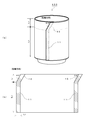
- FIG. 1 is an explanatory view showing a film label can 100 according to the present invention.
- 1A shows a form in which a film label is attached to a can body
- FIG. 1B shows a form in which the film label is developed.
- the overlap portion 10 scheduled for neck-in molding is inclined at an angle ⁇ , for example, 30 ° with respect to the can axis direction
- the can body overlap portion 11 is parallel to the can axis direction. It is configured.
- FIG. 1 (b) is a development view of the can body film label of FIG. 1 (a).
- L 1 15 mm
- L 2 109 mm
- L 3 2 mm.
- the said dimension example is a case of the can diameter 211.
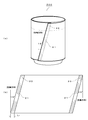
- FIG. 2 is an explanatory view showing the film label can 200 according to the first embodiment of the present invention.
- 2A shows a form in which a film label is attached to a can body
- FIG. 2B shows a form in which the film label is developed.
- the can body film label 200 is inclined not only at the overlap portion 20 where neck-in molding is planned, but also at the overlap portion 21 of the can body portion with respect to the can axis direction by an angle ⁇ , for example, 15 °. It is configured.
- FIG. 2B is a development view of the film label in which the direction of the overlap portion 20 where the neck-in molding is scheduled and the overlap portion 21 of the can body portion is inclined by 15 ° with respect to the can axis direction.
- L 4 2 mm.
- the said dimension example is a case of the can diameter 211.
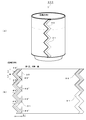
- FIG. 3 is an explanatory view showing a film label can 300 according to Embodiment 2 of the present invention.
- Fig.3 (a) shows the form which stuck the film label to the can body, and the same (b) shows the form which expand
- the can body film label 300 has a predetermined angle ⁇ or ⁇ in a zigzag manner with respect to the direction of the can axis not only in the overlap portion 30 where neck-in molding is scheduled, but also in the direction of the overlap portion 31 of the can body portion.
- ⁇ is alternately inclined. For example, ⁇ is 45 °.
- the direction of the overlap portion 31 of the can body portion is inclined alternately at a predetermined angle ⁇ or ⁇ with respect to the can axis direction. Therefore, the unstable phenomenon caused by the compression molding to the material that occurs at the time of neck-in molding is less likely to occur in the overlap portion 30, and the occurrence of neck-in wrinkles is suitably suppressed in the necking molding of the can body.
- FIG. 3 (b) shows the development of the can body film label in which the direction of the overlap portion 30 and the overlap portion 31 of the can body portion, which are scheduled to be neck-in-molded, are alternately inclined by 45 ° with respect to the can axis direction.
- L 5 3 mm
- L 6 3 mm
- L 7 2 mm.
- the said dimension example is a case of the can diameter 211.
- the film label can of the present invention can be applied to a film label can that suitably suppresses generation of neck-in wrinkles in necking molding of a can body.
Landscapes
- Engineering & Computer Science (AREA)
- Mechanical Engineering (AREA)
- Details Of Rigid Or Semi-Rigid Containers (AREA)
- Labeling Devices (AREA)
- Lining Or Joining Of Plastics Or The Like (AREA)
- Containers Having Bodies Formed In One Piece (AREA)
- Blow-Moulding Or Thermoforming Of Plastics Or The Like (AREA)
Abstract
缶胴のネッキング成形におけるネックインしわの発生を好適に抑制するフィルムラベル缶を提供するために、 フィルムラベルを缶胴に貼着する際に、ネックイン成形が予定されているオーバーラップ部分10について、缶軸方向に対し例えば30°傾斜するようにフィルムラベルを貼着することによって、缶胴のネッキング成形におけるネックインしわの発生を好適に抑制することが出来るようにした。
Description
本発明は、缶胴のネッキング成形においてフィルムラベルのオーバーラップ部に発生する缶内側への凹み(以後ネックインしわ)を好適に抑制するフィルムラベル缶に関するものである。
従来、缶胴部の形状や形成材料の如何に拘わらず、その缶胴部の表面に種々の美しい加飾を施すことが出来るように、缶胴長より若干長めにフィルムラベルをカットし、缶胴の外周面にフィルムラベルを巻きカットしたフィルムラベルの両端部を重ね合わせてオーバーラップ部を形成する。次に、熱ローラ等によってフィルムラベルを缶胴部に貼着する。その後、缶胴端部にネックイン成形を施すことによって、2ピース缶用の缶本体を製造する技術が知られている(例えば、特許文献1および特許文献2を参照。)。
缶胴のネックイン成形では、テーパ形状のネック成形ダイに缶胴の口部を押し込むことによって、缶胴の口部が徐々に縮径されて缶胴のネック部が成形される。その際、缶胴と「ネック成形ダイ」との軸芯がズレないように、缶胴は内部に円柱状中子が挿入された状態で、ネック成形ダイ中に押し込まれ缶胴ネック部が縮径成形される(例えば、特許文献3を参照。)。
缶胴のネックイン成形では、テーパ形状のネック成形ダイに缶胴の口部を押し込むことによって、缶胴の口部が徐々に縮径されて缶胴のネック部が成形される。その際、缶胴と「ネック成形ダイ」との軸芯がズレないように、缶胴は内部に円柱状中子が挿入された状態で、ネック成形ダイ中に押し込まれ缶胴ネック部が縮径成形される(例えば、特許文献3を参照。)。
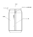
上記従来の缶胴のフィルムラベルのオーバーラップ部の長手方向(以下オーバーラップの方向)は、缶軸方向に対して平行に構成されているため、ネッキング成形において、その部位に縮径に伴う圧縮成分が作用すると、オーバーラップの段差部で、シワが発生する問題があった。
そこで、本発明は、上記実情に鑑み創案されたものであって、その目的は、缶胴のネッキング成形におけるネックインしわの発生を好適に抑制するフィルムラベル缶を提供することである。
そこで、本発明は、上記実情に鑑み創案されたものであって、その目的は、缶胴のネッキング成形におけるネックインしわの発生を好適に抑制するフィルムラベル缶を提供することである。
前記目的を達成するために、請求項1に記載のフィルムラベル缶は、缶胴の外周面にフィルムラベルの両端部をオーバーラップさせて巻き付けて貼着した缶胴であって、前記オーバーラップ部の内、少なくともネックイン成形が予定されている缶胴部分のオーバーラップ部の方向を、缶軸方向に対し傾斜させることを特徴とする。
本願発明者は、缶胴のネックイン成形時においてフィルムラベルのネックインしわの発生を抑制する方法について鋭意研究したところ、ネックイン成形が予定されている缶胴のオーバーラップ部の方向が、缶軸方向に対して傾斜していることによって、ネックイン成形時に生じる、材料への圧縮成形による不安定現象が発生し難くなりその結果、ネックインしわの発生が好適に抑制されることを見出した。
さらに詳述すると、ネックインしわは缶軸方向に平行に発生する。オーバーラップ部では、フィルムラベルが二重になっているため、缶外周から盛り上がっている。このため、オーバーラップ部はネックインダイから強く押されて、缶内側方向に盛り上がり、ネックインしわとなる。前述したように、ネックインしわが発生する方向は缶軸方向に平行であり、さらにオーバーラップ部の方向が缶軸方向に平行である従来の構成では、ネックインしわが助長され、オーバーラップ部に大きなネックインしわが発生する。本件では、オーバーラップ部の方向を、缶軸方向からずらせて、傾斜させた結果、ネックインしわの発生が抑制されることが判明した。上記より推察すると、傾斜の大きい方が、しわの抑制効果は大きくなると考えられる。
本願発明者は、缶胴のネックイン成形時においてフィルムラベルのネックインしわの発生を抑制する方法について鋭意研究したところ、ネックイン成形が予定されている缶胴のオーバーラップ部の方向が、缶軸方向に対して傾斜していることによって、ネックイン成形時に生じる、材料への圧縮成形による不安定現象が発生し難くなりその結果、ネックインしわの発生が好適に抑制されることを見出した。
さらに詳述すると、ネックインしわは缶軸方向に平行に発生する。オーバーラップ部では、フィルムラベルが二重になっているため、缶外周から盛り上がっている。このため、オーバーラップ部はネックインダイから強く押されて、缶内側方向に盛り上がり、ネックインしわとなる。前述したように、ネックインしわが発生する方向は缶軸方向に平行であり、さらにオーバーラップ部の方向が缶軸方向に平行である従来の構成では、ネックインしわが助長され、オーバーラップ部に大きなネックインしわが発生する。本件では、オーバーラップ部の方向を、缶軸方向からずらせて、傾斜させた結果、ネックインしわの発生が抑制されることが判明した。上記より推察すると、傾斜の大きい方が、しわの抑制効果は大きくなると考えられる。
請求項2に記載のフィルムラベル缶では、前記ネックイン成形が予定されているオーバーラップ部の方向を、缶軸方向に対し効果が認められる傾斜角度の規定をした。傾斜角度は小さいとネックインしわの発生を抑制する効果は少なく、又傾斜角度が大きいと、ネックインしわの発生を抑制する効果は大きいが、フィルムラベルの打ち抜き操作や、貼着操作が困難になるため、缶軸方向に対し10°~60°の傾斜が実用的であると判断している。
又別のフィルムラベルの貼着方法では、オーバーラップ部分を缶軸方向に対しジグザグ状に形成することによって、大きな傾斜角度でありながら、フィルムラベルの打ち抜きや貼着操作を容易にすることを両立しており、缶胴のネッキング成形におけるネックインしわの発生を好適に抑制することが出来るようにした。
又別のフィルムラベルの貼着方法では、オーバーラップ部分を缶軸方向に対しジグザグ状に形成することによって、大きな傾斜角度でありながら、フィルムラベルの打ち抜きや貼着操作を容易にすることを両立しており、缶胴のネッキング成形におけるネックインしわの発生を好適に抑制することが出来るようにした。
本発明のフィルムラベル缶によれば、缶胴のネッキング成形におけるネックインしわの発生を好適に抑制することが出来る。
以下、図に示す実施の形態により本発明をさらに詳細に説明する。なお、これにより本発明が限定されるものではない。
図1は、本発明に係るフィルムラベル缶100を示す説明図である。なお、図1(a)は缶胴にフィルムラベルを貼着した形態を示し、同(b)は前記フィルムラベルを展開した形態を示す。
このフィルムラベル缶100は、ネックイン成形が予定されているオーバーラップ部10が缶軸方向に対し角度θ、例えば30°で傾斜し、缶胴部オーバーラップ部11が缶軸方向に対し平行に構成されている。
このフィルムラベル缶100は、ネックイン成形が予定されているオーバーラップ部10が缶軸方向に対し角度θ、例えば30°で傾斜し、缶胴部オーバーラップ部11が缶軸方向に対し平行に構成されている。
このように、ネックイン成形が予定されているオーバーラップ部10の方向が缶軸方向に対して傾斜していることによって、ネックイン成形時に生じる、材料への圧縮成形による不安定現象がオーバーラップ部10に発生し難くなり、缶胴のネッキング成形においてネックインしわの発生が好適に抑制される。
図1(b)は、図1(a)の缶胴フィルムラベルの展開図である。
寸法例を挙げると、例えば、L1=15mm、L2=109mm、L3=2mmである。なお、上記寸法例は、缶径211の場合である。
寸法例を挙げると、例えば、L1=15mm、L2=109mm、L3=2mmである。なお、上記寸法例は、缶径211の場合である。
図2は、本発明の実施例1に係るフィルムラベル缶200を示す説明図である。なお、図2(a)は缶胴にフィルムラベルを貼着した形態を示し、同(b)は前記フィルムラベルを展開した形態を示す。
上記缶胴フィルムラベル200は、ネックイン成形が予定されているオーバーラップ部20だけでなく、缶胴部のオーバーラップ部21の方向についても缶軸方向に対し角度θ、例えば15°傾斜して構成されている。
上記缶胴フィルムラベル200は、ネックイン成形が予定されているオーバーラップ部20だけでなく、缶胴部のオーバーラップ部21の方向についても缶軸方向に対し角度θ、例えば15°傾斜して構成されている。
このように、ネックイン成形が予定されているオーバーラップ部20だけでなく、缶胴部のオーバーラップ部21の方向についても缶軸方向に対し傾斜していることにより、ネックイン成形時に生じる、材料への圧縮成形による不安定現象がオーバーラップ部20に発生し難くなり、缶胴のネッキング成形においてネックインしわの発生が好適に抑制される。
図2(b)は、ネックイン成形が予定されているオーバーラップ部20及び缶胴部のオーバーラップ部21の方向が缶軸方向に対し15°傾斜した前記フィルムラベルの展開図である。
寸法例を挙げると、例えば、L4=2mmである。なお、上記寸法例は、缶径211の場合である。
寸法例を挙げると、例えば、L4=2mmである。なお、上記寸法例は、缶径211の場合である。
図3は、本発明の実施例2に係るフィルムラベル缶300を示す説明図である。なお、図3(a)は缶胴にフィルムラベルを貼着した形態を示し、同(b)はそれを展開した形態を示す。
この缶胴フィルムラベル300は、ネックイン成形が予定されているオーバーラップ部30だけでなく、缶胴部のオーバーラップ部31の方向についても缶軸方向に対してジグザクに所定の角度θ又は-θ交互に傾斜して形成されている。なお、θとしては、例えば45°である。
この缶胴フィルムラベル300は、ネックイン成形が予定されているオーバーラップ部30だけでなく、缶胴部のオーバーラップ部31の方向についても缶軸方向に対してジグザクに所定の角度θ又は-θ交互に傾斜して形成されている。なお、θとしては、例えば45°である。
このように、ネックイン成形が予定されているオーバーラップ部30だけでなく、缶胴部のオーバーラップ部31の方向についても缶軸方向に対しジグザクに所定の角度θ又は-θ交互に傾斜して構成されていることにより、ネックイン成形時に生じる、材料への圧縮成形による不安定現象がオーバーラップ部30に発生し難くなり、缶胴のネッキング成形においてネックインしわの発生が好適に抑制される。
図3(b)は、ネックイン成形が予定されているオーバーラップ部30及び缶胴部のオーバーラップ部31の方向が缶軸方向に対しジグザクに45°交互に傾斜した缶胴フィルムラベルの展開図である。
寸法例を挙げると、例えば、L5=3mm、L6=3mm、L7=2mmである。なお、上記寸法例は、缶径211の場合である。
寸法例を挙げると、例えば、L5=3mm、L6=3mm、L7=2mmである。なお、上記寸法例は、缶径211の場合である。
本発明のフィルムラベル缶は、缶胴のネッキング成形におけるネックインしわの発生を好適に抑制するフィルムラベル缶に適用され得る。
10,20,30 ネックイン成形予定オーバーラップ部
11,21,31 缶胴部オーバーラップ部
100,200,300 フィルムラベル缶
500 従来のフィルムラベル缶
11,21,31 缶胴部オーバーラップ部
100,200,300 フィルムラベル缶
500 従来のフィルムラベル缶
Claims (2)
- フィルムラベルの両端部をオーバーラップさせて缶胴の外周面にフィルムラベルを貼着した缶胴であって、
前記オーバーラップ部の内、少なくともネックイン成形が予定されている缶胴部分のオーバーラップ部の長手方向が、缶軸方向に対し傾斜していることを特徴とするフィルムラベル缶。 - 前記オーバーラップ部分の長手方向が、缶軸方向に対し10°~60°傾斜していることを特徴とする請求項1に記載のフィルムラベル缶。
Priority Applications (1)
| Application Number | Priority Date | Filing Date | Title |
|---|---|---|---|
| CN201080007386.9A CN102317170B (zh) | 2009-02-12 | 2010-02-10 | 薄膜标签式罐 |
Applications Claiming Priority (2)
| Application Number | Priority Date | Filing Date | Title |
|---|---|---|---|
| JP2009-029474 | 2009-02-12 | ||
| JP2009029474A JP4911328B2 (ja) | 2009-02-12 | 2009-02-12 | フィルムラベル缶 |
Publications (2)
| Publication Number | Publication Date |
|---|---|
| WO2010092978A2 true WO2010092978A2 (ja) | 2010-08-19 |
| WO2010092978A3 WO2010092978A3 (ja) | 2011-02-24 |
Family
ID=42562140
Family Applications (1)
| Application Number | Title | Priority Date | Filing Date |
|---|---|---|---|
| PCT/JP2010/051959 Ceased WO2010092978A2 (ja) | 2009-02-12 | 2010-02-10 | フィルムラベル缶 |
Country Status (3)
| Country | Link |
|---|---|
| JP (1) | JP4911328B2 (ja) |
| CN (1) | CN102317170B (ja) |
| WO (1) | WO2010092978A2 (ja) |
Family Cites Families (9)
| Publication number | Priority date | Publication date | Assignee | Title |
|---|---|---|---|---|
| JPS58187342A (ja) * | 1982-04-28 | 1983-11-01 | 東洋製罐株式会社 | レトルト殺菌可能なプラスチツク罐胴及びその製法 |
| JPH0457747A (ja) * | 1990-06-19 | 1992-02-25 | Kuwabara Yasunaga | 端部加工性に優れた金属缶胴体及びその製造方法 |
| JP3365902B2 (ja) * | 1996-02-09 | 2003-01-14 | 大和製罐株式会社 | フイルム貼着缶体およびその製造方法 |
| JPH11157545A (ja) * | 1997-11-26 | 1999-06-15 | Fuji Seal Inc | 2ピース缶用の缶本体 |
| JPH11157546A (ja) * | 1997-11-27 | 1999-06-15 | Fuji Seal Inc | 缶及びその製造方法 |
| JP2000229642A (ja) * | 1999-02-15 | 2000-08-22 | Fuji Seal Inc | 金属缶用ラベル及びその金属缶用ラベルを装着した金属缶 |
| JP4478287B2 (ja) * | 2000-04-12 | 2010-06-09 | 東罐興業株式会社 | コップ状容器 |
| US6818271B2 (en) * | 2002-02-12 | 2004-11-16 | Spear Usa, Llc | Adhesive coated thin film label |
| WO2008018546A1 (en) * | 2006-08-09 | 2008-02-14 | Dai Nippon Printing Co., Ltd. | In-mold label container |
-
2009
- 2009-02-12 JP JP2009029474A patent/JP4911328B2/ja active Active
-
2010
- 2010-02-10 CN CN201080007386.9A patent/CN102317170B/zh not_active Expired - Fee Related
- 2010-02-10 WO PCT/JP2010/051959 patent/WO2010092978A2/ja not_active Ceased
Also Published As
| Publication number | Publication date |
|---|---|
| JP2010184723A (ja) | 2010-08-26 |
| WO2010092978A3 (ja) | 2011-02-24 |
| CN102317170B (zh) | 2015-07-01 |
| CN102317170A (zh) | 2012-01-11 |
| JP4911328B2 (ja) | 2012-04-04 |
Similar Documents
| Publication | Publication Date | Title |
|---|---|---|
| CN102712026A (zh) | 制造具有卷曲端的罐的方法和装置、这种罐以及罐体 | |
| JP2013103250A (ja) | 管端成形方法 | |
| JP2019025541A (ja) | 缶製造方法、缶製造装置、缶、缶製造工具セット | |
| US8516682B2 (en) | Manufacturing method of a stator core of rotating electrical machine | |
| JP4911328B2 (ja) | フィルムラベル缶 | |
| JP4906849B2 (ja) | 鋼管の拡管成形方法および鋼管の拡管成形装置 | |
| CN105555431B (zh) | 罐体端部的制造 | |
| JP2013188319A (ja) | ストローの製造方法 | |
| JP5457151B2 (ja) | 溶接用部材の製造方法 | |
| JP4746655B2 (ja) | パイプ曲げ加工装置及びパイプ曲げ加工方法 | |
| JP4978775B2 (ja) | 管状部材 | |
| JP5661312B2 (ja) | 巻芯 | |
| JP6381377B2 (ja) | 印刷用版 | |
| JP6620721B2 (ja) | 管の曲げ装置 | |
| JP2019051532A (ja) | 金属パイプの回転引き曲げ加工方法 | |
| JP6373106B2 (ja) | 金属帯巻取方法 | |
| JP2010158712A (ja) | パイプの接合方法 | |
| JP6433301B2 (ja) | ブシュ及びその製造方法 | |
| JP2007021564A (ja) | タブの製造方法およびタブ並びに缶蓋 | |
| JP4116011B2 (ja) | 角缶の製造方法 | |
| JP2008177338A (ja) | 偏平素子の製造方法 | |
| JP2012162286A (ja) | 金属線材梱包体および切断用ワイヤ | |
| JP2007008419A (ja) | ボディーサイドアウター及びその成形方法 | |
| JP2022065732A (ja) | 金属メッシュ成形体の製造方法 | |
| JP5824484B2 (ja) | パネル部材の成形方法及びパネル部材成形用アウタ部材 |
Legal Events
| Date | Code | Title | Description |
|---|---|---|---|
| WWE | Wipo information: entry into national phase |
Ref document number: 201080007386.9 Country of ref document: CN |
|
| 121 | Ep: the epo has been informed by wipo that ep was designated in this application |
Ref document number: 10741255 Country of ref document: EP Kind code of ref document: A2 |
|
| NENP | Non-entry into the national phase |
Ref country code: DE |
|
| 122 | Ep: pct application non-entry in european phase |
Ref document number: 10741255 Country of ref document: EP Kind code of ref document: A2 |