WO2010090288A1 - 冷凍サイクル用容器と冷凍サイクル装置 - Google Patents
冷凍サイクル用容器と冷凍サイクル装置 Download PDFInfo
- Publication number
- WO2010090288A1 WO2010090288A1 PCT/JP2010/051719 JP2010051719W WO2010090288A1 WO 2010090288 A1 WO2010090288 A1 WO 2010090288A1 JP 2010051719 W JP2010051719 W JP 2010051719W WO 2010090288 A1 WO2010090288 A1 WO 2010090288A1
- Authority
- WO
- WIPO (PCT)
- Prior art keywords
- refrigeration cycle
- container
- refrigerant pipe
- container body
- brazing
- Prior art date
- Legal status (The legal status is an assumption and is not a legal conclusion. Google has not performed a legal analysis and makes no representation as to the accuracy of the status listed.)
- Ceased
Links
Images






Classifications
-
- B—PERFORMING OPERATIONS; TRANSPORTING
- B23—MACHINE TOOLS; METAL-WORKING NOT OTHERWISE PROVIDED FOR
- B23K—SOLDERING OR UNSOLDERING; WELDING; CLADDING OR PLATING BY SOLDERING OR WELDING; CUTTING BY APPLYING HEAT LOCALLY, e.g. FLAME CUTTING; WORKING BY LASER BEAM
- B23K1/00—Soldering, e.g. brazing, or unsoldering
-
- B—PERFORMING OPERATIONS; TRANSPORTING
- B23—MACHINE TOOLS; METAL-WORKING NOT OTHERWISE PROVIDED FOR
- B23K—SOLDERING OR UNSOLDERING; WELDING; CLADDING OR PLATING BY SOLDERING OR WELDING; CUTTING BY APPLYING HEAT LOCALLY, e.g. FLAME CUTTING; WORKING BY LASER BEAM
- B23K1/00—Soldering, e.g. brazing, or unsoldering
- B23K1/0008—Soldering, e.g. brazing, or unsoldering specially adapted for particular articles or work
- B23K1/0012—Brazing of heat exchangers
-
- B—PERFORMING OPERATIONS; TRANSPORTING
- B23—MACHINE TOOLS; METAL-WORKING NOT OTHERWISE PROVIDED FOR
- B23K—SOLDERING OR UNSOLDERING; WELDING; CLADDING OR PLATING BY SOLDERING OR WELDING; CUTTING BY APPLYING HEAT LOCALLY, e.g. FLAME CUTTING; WORKING BY LASER BEAM
- B23K9/00—Arc welding or cutting
- B23K9/02—Seam welding; Backing means; Inserts
- B23K9/028—Seam welding; Backing means; Inserts for curved planar seams
- B23K9/0288—Seam welding; Backing means; Inserts for curved planar seams for welding of tubes to tube plates
-
- B—PERFORMING OPERATIONS; TRANSPORTING
- B23—MACHINE TOOLS; METAL-WORKING NOT OTHERWISE PROVIDED FOR
- B23K—SOLDERING OR UNSOLDERING; WELDING; CLADDING OR PLATING BY SOLDERING OR WELDING; CUTTING BY APPLYING HEAT LOCALLY, e.g. FLAME CUTTING; WORKING BY LASER BEAM
- B23K9/00—Arc welding or cutting
- B23K9/16—Arc welding or cutting making use of shielding gas
- B23K9/173—Arc welding or cutting making use of shielding gas and of a consumable electrode
-
- B—PERFORMING OPERATIONS; TRANSPORTING
- B23—MACHINE TOOLS; METAL-WORKING NOT OTHERWISE PROVIDED FOR
- B23K—SOLDERING OR UNSOLDERING; WELDING; CLADDING OR PLATING BY SOLDERING OR WELDING; CUTTING BY APPLYING HEAT LOCALLY, e.g. FLAME CUTTING; WORKING BY LASER BEAM
- B23K9/00—Arc welding or cutting
- B23K9/23—Arc welding or cutting taking account of the properties of the materials to be welded
- B23K9/232—Arc welding or cutting taking account of the properties of the materials to be welded of different metals
-
- F—MECHANICAL ENGINEERING; LIGHTING; HEATING; WEAPONS; BLASTING
- F25—REFRIGERATION OR COOLING; COMBINED HEATING AND REFRIGERATION SYSTEMS; HEAT PUMP SYSTEMS; MANUFACTURE OR STORAGE OF ICE; LIQUEFACTION SOLIDIFICATION OF GASES
- F25B—REFRIGERATION MACHINES, PLANTS OR SYSTEMS; COMBINED HEATING AND REFRIGERATION SYSTEMS; HEAT PUMP SYSTEMS
- F25B43/00—Arrangements for separating or purifying gases or liquids; Arrangements for vaporising the residuum of liquid refrigerant, e.g. by heat
- F25B43/006—Accumulators
-
- B—PERFORMING OPERATIONS; TRANSPORTING
- B23—MACHINE TOOLS; METAL-WORKING NOT OTHERWISE PROVIDED FOR
- B23K—SOLDERING OR UNSOLDERING; WELDING; CLADDING OR PLATING BY SOLDERING OR WELDING; CUTTING BY APPLYING HEAT LOCALLY, e.g. FLAME CUTTING; WORKING BY LASER BEAM
- B23K2101/00—Articles made by soldering, welding or cutting
- B23K2101/04—Tubular or hollow articles
- B23K2101/12—Vessels
-
- B—PERFORMING OPERATIONS; TRANSPORTING
- B23—MACHINE TOOLS; METAL-WORKING NOT OTHERWISE PROVIDED FOR
- B23K—SOLDERING OR UNSOLDERING; WELDING; CLADDING OR PLATING BY SOLDERING OR WELDING; CUTTING BY APPLYING HEAT LOCALLY, e.g. FLAME CUTTING; WORKING BY LASER BEAM
- B23K2101/00—Articles made by soldering, welding or cutting
- B23K2101/34—Coated articles ; Surface treated articles
-
- B—PERFORMING OPERATIONS; TRANSPORTING
- B23—MACHINE TOOLS; METAL-WORKING NOT OTHERWISE PROVIDED FOR
- B23K—SOLDERING OR UNSOLDERING; WELDING; CLADDING OR PLATING BY SOLDERING OR WELDING; CUTTING BY APPLYING HEAT LOCALLY, e.g. FLAME CUTTING; WORKING BY LASER BEAM
- B23K2103/00—Materials to be soldered, welded or cut
- B23K2103/18—Dissimilar materials
- B23K2103/22—Ferrous alloys and copper or alloys thereof
Definitions
- the present invention relates to a refrigeration cycle container that includes a refrigeration cycle container together with a refrigeration cycle container, such as an accumulator, a refrigerant tank, and an oil separator, and a refrigeration cycle container.
- a refrigeration cycle container such as an accumulator, a refrigerant tank, and an oil separator
- brazing is a joining method in which a brazing material melted into a gap (0.05 to 0.1 mm) between a pair of heated joint parts is poured using a capillary phenomenon. As a result, a thin alloy layer is formed by diffusion reaction between the joint metal and the brazing material, and joint parts are joined to each other.
- the pipe connection structure of the compressor which includes a compressor that compresses the refrigerant, an accumulator (a refrigeration cycle container) that stores the refrigerant, and a suction pipe that connects the compressor and the accumulator and guides the refrigerant
- a technique for connecting parts together by brazing or welding is disclosed (for example, see Japanese Patent Application Laid-Open No. 2004-360476).
- Brazing used in the invention of Japanese Patent Application Laid-Open No. 2004-360476 is difficult to mechanize as compared with welding, and relies heavily on the manual work and skill of the operator. Therefore, in the case of a container for a refrigeration cycle with many brazing points, it takes a lot of time and affects the man-hours.
- the base material and the wire are heated, and copper, which is the main component of the wire, is melted in an inert gas atmosphere, and this is introduced into the gap between the base materials to be brazed.
- This type of welding method is characterized in that it generates less spatter and is excellent in appearance.
- the present invention has been made on the basis of the above circumstances.
- the purpose of the present invention is to reduce labor and work by adopting an optimum means other than brazing when joining the refrigerant pipe to the container body.
- An object of the present invention is to provide a container for a refrigeration cycle that shortens the time and contributes to cost reduction.
- an object of the present invention is to provide a refrigeration cycle apparatus that is provided with the above-described refrigeration cycle container and can be improved in reliability by constituting a refrigeration cycle.
- the container for refrigeration cycle and the refrigeration cycle apparatus of the present invention are configured as follows.
- ⁇ A refrigerant pipe is joined to the container body by MIG (metal inert gas) brazing. Further, the refrigeration cycle apparatus configures a refrigeration cycle by connecting a compressor, a condenser, an expansion device, an evaporator, and the refrigeration cycle container described above via a refrigerant pipe.
- MIG metal inert gas
- FIG. 1 is a front view of a refrigeration cycle container according to a first embodiment of the present invention.
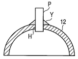
- FIG. 2 is a cross-sectional view showing a joint structure between the upper end plate of the container body and the refrigerant pipe constituting the container for the refrigeration cycle.
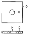
- FIG. 3A is an explanatory view showing a process of processing the upper end plate.
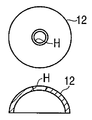
- FIG. 3B is an explanatory view showing a process of processing the upper end plate.
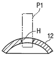
- FIG. 3C is an explanatory diagram showing a process of processing the upper end plate.
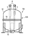
- FIG. 4 is a front view of the refrigeration cycle container according to the second embodiment of the present invention.
- FIG. 5A is a cross-sectional view showing a joint structure between a container main body and a refrigerant pipe constituting the container for the refrigeration cycle.
- FIG. 5B is a cross-sectional view showing a joint structure between the container body and the refrigerant pipe.
- FIG. 6A is a front view showing a container for a refrigeration cycle according to a third embodiment of the present invention.
- FIG. 6B is a side view showing the refrigeration cycle container.
- FIG. 7 is a front view showing a refrigeration cycle container according to a fourth embodiment of the present invention.
- FIG. 8A is a cross-sectional view showing a joint structure between a container body and a refrigerant pipe according to a fifth embodiment of the present invention.
- FIG. 8B is a plan view showing a joint structure between a container body and a refrigerant pipe according to a fifth embodiment of the present invention.
- FIG. 6A is a front view showing a container for a refrigeration cycle according to a third embodiment of the present invention.
- FIG. 6B is a side view showing the refrigeration cycle container.
- FIG. 7 is a front view showing a refrigeration cycle container according to
- FIG. 9A is a plan view showing a joint structure between a container body and a refrigerant pipe according to a sixth embodiment of the present invention.
- FIG. 9B is a cross-sectional view showing a joint structure between a container body and a refrigerant pipe according to a sixth embodiment of the present invention.
- FIG. 10 is a configuration diagram of the refrigeration cycle of the refrigeration cycle apparatus according to the seventh embodiment of the present invention.
- FIG. 10 is a configuration diagram of a refrigeration cycle of a refrigeration cycle apparatus, for example, an air conditioner.
- reference numeral 1 denotes a compressor that compresses the sucked refrigerant into a high-temperature and high-pressure gas refrigerant and discharges it to the refrigerant pipe P.
- the condenser 2 is communicated with the refrigerant pipe P to condense the guided gas refrigerant and convert it into a liquid refrigerant.
- the expansion valve 3 which is an expansion device is communicated with the condenser 2 through a refrigerant pipe P to adiabatically expand the led liquid refrigerant. Further, an evaporator 4 is communicated with the expansion valve 3 via a refrigerant pipe P to evaporate the refrigerant, and the latent heat of vaporization at this time is taken from the heat exchange air and changed into cold air. That is, a freezing (cooling) action is obtained.
- the accumulator 5 communicates with the evaporator 4 via a refrigerant pipe P to separate the introduced evaporated refrigerant into a gas and liquid. Only the separated gas refrigerant is sucked into the compressor 1 through the refrigerant pipe P, and the above-described refrigeration cycle is repeated again. By providing the accumulator 5, liquid compressor is not sucked by the compressor 1, and liquid compression is prevented.
- an oil separator, a liquid tank, etc. (not shown) are also used, and together with the accumulator 5 are collectively referred to as a “refrigeration cycle container R”.
- a refrigeration cycle container R an oil separator, a liquid tank, etc. (not shown) are also used, and together with the accumulator 5 are collectively referred to as a “refrigeration cycle container R”.
- refrigeration cycle container R a joining structure between the refrigeration cycle container R and the refrigerant pipe P will be described.
- FIG. 1 is a front view of a refrigeration cycle container Ra according to a first embodiment.
- the refrigeration cycle container Ra includes a container body 10 provided with a separation plate 10a therein, a first refrigerant pipe P1 joined to the upper end of the container body 10, and one end joined to the bottom surface of the container body 10 and the other end. Is formed to rise inside the container body 10, one end is joined to the second refrigerant pipe P ⁇ b> 2 via the bottom surface of the container body 10, and the other end is substantially U-shaped outside the container body 10. It comprises a bent third refrigerant pipe P3.
- the first refrigerant pipe P1 is connected to the evaporator 4, and the refrigerant evaporated here is guided into the container body 10 through the first refrigerant pipe P1.
- a separation plate 10a is provided inside the container body 10 that faces the opening end of the first refrigerant pipe P1, and the vaporized refrigerant passes through the separator plate 10a to be separated into a gas refrigerant and a liquid refrigerant.
- the liquid refrigerant accumulates in the bottom of the container body 10, and the gas refrigerant is sucked from the open end of the second refrigerant pipe P2 and led to the third refrigerant pipe P3, and further sucked into the compressor 1 and compressed.
- the liquid refrigerant accumulated at the inner bottom of the container body 10 evaporates as time elapses or under the influence of the temperature of the external air, becomes a gas refrigerant, and is sucked from the open end of the second refrigerant pipe P2.
- the container body 10 includes a cylindrical lens barrel 11 having upper and lower ends opened and a separation plate 10a fitted in the upper end, and an upper end opening of the lens barrel 11.
- the upper end plate 12 is welded so as to be closed, and the lower end plate 13 is welded so as to close the lower end opening of the barrel 11.
- a plurality of support legs 14 are attached to the peripheral surface of the lower end plate 13 with a predetermined interval by welding. All the components of the container body 10 are made of iron, and the entire peripheral surface including the support legs 14 is painted.
- a copper pipe is used for the first refrigerant pipe P1.
- coolant pipe P1 with respect to the upper end plate 12 which comprises the container main body 10 is as showing in FIG.
- a mounting hole H is provided in the central portion of the upper end plate 12, and the lower end portion of the first refrigerant pipe P1 is inserted and temporarily held therein. In this state, the peripheral surface of the first refrigerant pipe P1 and the peripheral portion of the mounting hole H are processed by MIG brazing Y.
- brazing material used for MIG brazing Y is mainly composed of copper and the brazing material itself serves as an electrode, it is also called “consumable electrode type arc brazing”. In other words, brazing is performed by arc heat, and there is a relatively low distortion and pinhole generation due to local heating, and the processing speed is high.
- the processing sequence as the refrigeration cycle container Ra is such that when the upper end plate 12 is in a single state before the upper end plate 12 is joined to the end tube 11, the first refrigerant pipe P1 is attached to the upper end plate 12 by MIG brazing Y. Join.
- the second refrigerant pipe P2 may be an iron pipe, but the third refrigerant pipe P3 is a copper pipe.
- the second refrigerant pipe P2 and the third refrigerant pipe P3 are joined to the lower end plate 13 by MIG brazing Y.
- the second refrigerant pipe P2 and the lower end plate 13 are joined by MIG brazing Y, and then one end of the third refrigerant pipe P3 is connected to the end of the lower end plate 13 and the second refrigerant pipe P2. And is joined by MIG brazing Y.
- the upper end plate 12 joined with the first refrigerant pipe P1 is welded to the upper end portion of the lens barrel 11, and the upper end opening of the lens barrel 11 is closed.
- the lower end plate 13 in which the second refrigerant pipe P2 and the third refrigerant pipe P3 are joined is welded to the lower end portion of the lens barrel 11, and the lower end opening of the lens barrel 11 is closed. Therefore, the container body 10 is assembled.
- the processing time required for joining at one location is about 40 seconds for silver brazing and about 10 seconds for MIG brazing Y.
- the cost of the brazing material is 27 thousand yen for silver brazing per kilogram (at the time of filing), and the copper brazing material used for the MIG brazing Y can be purchased for 5,000 yen (same as above).
- MIG brazing Y has many advantages over silver brazing, and therefore, the labor required for joining the container body 10 and the refrigerant pipes P1 to P3 can be reduced and the processing time can be shortened. Can contribute to cost reduction.
- FIG. 3A, FIG. 3B, and FIG. 3C are diagrams for explaining the manufacturing sequence of the upper end plate 12 constituting the container body 11 and the joining of the first refrigerant pipe P1. Although not particularly illustrated, the same applies to the joining of the lower end plate 13 and the second refrigerant pipe P2.
- a rectangular plate body D is prepared in plan view, and a mounting hole H is provided at the center.
- a rectangular plate D provided with a mounting hole H at the center is formed into a semicircular cross section by drawing. The peripheral end portion is aligned at the same position to form a substantially bowl-shaped upper end plate 12.
- the mounting hole H provided earlier has a cross-sectional taper shape in which the outer surface side diameter of the upper end plate 12 is larger than the inner surface side diameter.
- This is a cross-sectional shape that is inevitably formed by drawing a rectangular plate D having a predetermined plate thickness, and when the first refrigerant pipe P1 is inserted, a mounting hole on the outer surface side of the upper end plate 12 A certain amount of gap is generated from the H periphery.
- the mounting hole H has a tapered cross section.
- a conspicuous gap is formed on the outer surface side of the upper end plate 12 between the refrigerant pipe P1 and the periphery of the mounting hole H.
- the brazing material of MIG brazing Y can easily enter the gap, so that the bonding strength between the upper end plate 12 and the first refrigerant pipe P1 is increased.
- the iron material is selected for the barrel 11, the upper end plate 12, and the lower end plate 13 constituting the container body 10.
- the present invention is not limited to this.
- the refrigerant pipes P1 to P3 made of copper pipes are joined to the container body 10 by MIG brazing Y. There is no change in using a copper-based material as the brazing material, and the refrigerant pipes P1 to P3 can be firmly joined to the container body 10.
- FIG. 4 is a front view of the refrigeration cycle container Rb in the second embodiment. Although the overall height and diameter of the container main body 10 are different from those described above with reference to FIG.
- the refrigerant pipe is joined by two connecting refrigerant pipes P4 and P5 protruding upward from the upper end plate 12 constituting the container body 10 and MIG brazing Y through the connecting refrigerant pipes P4 and P5 and the upper end plate 12.
- the U-shaped refrigerant pipe P ⁇ b> 6 is accommodated in the container body 10.
- the connecting refrigerant pipes P4 and P5 are copper pipes
- the U-shaped refrigerant pipe P6 is an iron pipe. That is, the refrigerant pipe connected to the outside from the container main body 10 is a copper material, and the U-shaped refrigerant pipe P6 accommodated in the container main body 10 is the same iron material as the container main body 10.
- the iron material is used only for the U-shaped refrigerant pipe P6, but this refrigerant pipe P6 is housed inside the container body 10 and does not come into contact with external air, so that rust is hardly generated. By using inexpensive iron, it contributes to cost reduction. Naturally, there is no functional problem as the refrigeration cycle container Rb.
- FIG. 5A or FIG. 5B In order to join the two upper and lower refrigerant pipes P through the container body 10, a joining structure as shown in FIG. 5A or FIG. 5B is used.
- FIG. 5A the end portion of the upper refrigerant pipe Pa made of a copper pipe is inserted into the mounting hole H from the upper part of the container body 10. And the upper side refrigerant
- a brazing material mainly composed of copper is used, strong bonding can be obtained in a short time.
- the opening end of the lower refrigerant pipe Pb made of an iron pipe is applied so as to face the mounting hole H from the lower side of the container main body 10, and the lower refrigerant pipe Pb and the container main body 10 are joined by welding U. .
- the joining process is in two stages.
- the lower side refrigerant pipe Pb which is an iron pipe
- the container body 10 made of an iron material are usually welded U. That's okay. Since the inside of the completed container body 10 is free of oxygen, rust is unlikely to occur in the lower refrigerant pipe Pb.
- FIG. 5B shows another example of the joint structure.
- the opening end of the lower refrigerant pipe Pd is inserted into the mounting hole H from the lower part of the container body 10 and protrudes to the upper surface side of the container body 10 to some extent. This state is temporarily held and the opening end of the upper refrigerant pipe Pc is opposed to the opening end of the lower refrigerant pipe Pd from the upper part of the container body 10.
- the MIG brazing Y is performed simultaneously on the container body 10 and the upper end side refrigerant pipe Pc end portion and the lower side refrigerant pipe Pd end portion. As a joining process, only one step is required, and MIG brazing Y can ensure airtightness. And it remains unchanged that rust hardly occurs in the lower refrigerant pipe Pd inside the container body 10.
- FIG. 6 shows a horizontal refrigeration cycle container Rc as a third embodiment of the present invention.
- a plurality (at least two) of refrigerant pipes P are joined together by MIG brazing Y at intervals L along the axial direction of the horizontally placed container body 10A.
- the interval L must be set to about 150 mm or more.
- the MIG brazing Y can be automated. Specifically, a torch for holding the brazing material is necessary, and MIG brazing Y is performed while moving the torch along the periphery of the refrigerant pipe P.
- the second refrigerant pipe P and the second refrigerant pipe P are close to each other in order to perform the MIG brazing Y.
- the MIG brazing Y of the second refrigerant pipe P cannot be performed.
- FIG. 7 is a front view of a refrigeration cycle container according to a fourth embodiment of the present invention.
- the container body 10B is formed by joining the upper end plate 12 and the lower end plate 13 directly by welding. That is, the container main body 10B is configured without using the lens barrel 11 shown in FIG. 1, but there is no problem even if the lens barrel 11 is interposed between the upper and lower end plate 12 and 13.
- a stainless steel wire (SUS wire) 15 is wound around a joint portion between the upper end plate 12 and the lower end plate 13 constituting the container body 10B, and welding is performed from above the stainless steel wire 15.
- the joint portion is covered with a stainless material having an anticorrosive effect, and at least the repair coating on the joint portion becomes unnecessary.
- FIG. 8A and 8B are views for explaining a joining means according to the fifth embodiment of the present invention.
- FIG. 8A is a sectional view of the upper end plate 12 and
- FIG. 8B is a plan view thereof.
- the upper end plate 12 and the refrigerant pipe P are at normal temperature at the start of the operation, and are not heated, so it is difficult to join them. If it ends with incomplete joining, the refrigerant gas tends to leak from this part, and the reliability is lacking.
- the brazing material is applied to a part that is spaced apart from the peripheral surface of the refrigerant pipe P and heated. So-called preheating is performed, and the temperature rise of the upper end plate 12 is awaited.
- FIGS. 9A and 9B are views for explaining the joining means according to the sixth embodiment of the present invention.
- FIG. 9A is a plan view of the lower end plate 13 and
- FIG. 9B is a cross-sectional view.
- the opening end of the refrigerant pipe P is inserted into the mounting hole H provided in the lower end plate 13 and the opening end of the refrigerant pipe P is protruded to the inner surface side of the lower end plate 13 to some extent. Temporarily holding this state, the opening end portion peripheral surface of the refrigerant pipe P protruding from the inner surface side of the lower end plate 13 is MIG brazed to the lower end plate 13 to join the lower end plate 13 and the refrigerant pipe P.
- the lower end plate 13 is joined to the end tube 11 or the upper end plate 12 to constitute the container body 10 and completed as the container R for the refrigeration cycle. Then, it is subjected to a leak inspection for inspecting whether or not there is a leak from the joint portion.
- the length of the straight portion along the axial direction of the refrigerant pipe P joined to the lower end plate 13 is very short, and there is also one that is bent in a substantially L shape without a sufficient distance from the lower end plate 13. is there.
- a copper-aluminum-based brazing material is used for MIG brazing between the container body and the refrigerant pipe.
- the present invention it is possible to obtain a container for a refrigeration cycle that contributes to cost reduction by reducing the labor required for joining the container body and the refrigerant pipe and shortening the processing time. Furthermore, according to the present invention, there is obtained a refrigeration cycle apparatus provided with the above refrigeration cycle container and capable of improving reliability.
Landscapes
- Engineering & Computer Science (AREA)
- Mechanical Engineering (AREA)
- Physics & Mathematics (AREA)
- Plasma & Fusion (AREA)
- Chemical & Material Sciences (AREA)
- Materials Engineering (AREA)
- Analytical Chemistry (AREA)
- Power Engineering (AREA)
- Thermal Sciences (AREA)
- General Engineering & Computer Science (AREA)
- Arc Welding In General (AREA)
Abstract
Description
Claims (5)
- 容器本体と、
この容器本体に、メタルイナートガスブレージングにより接合される冷媒パイプと、
を具備することを特徴とする冷凍サイクル用容器。 - 前記容器本体は、高耐食性メッキ鋼板からなり、
前記冷媒パイプは複数本接合されていて、
そのうちの少なくとも一部は、銅パイプからなり、
前記メタルイナートガスブレージングは、銅を主成分とするろう材が用いられる
ことを特徴とする請求項1記載の冷凍サイクル用容器。 - 前記容器本体から外部に突出する冷媒パイプとして、銅パイプが用いられ、
前記容器本体の内部に収容される冷媒パイプとして、鉄パイプが用いられる
ことを特徴とする請求項2記載の冷凍サイクル用容器。 - 前記容器本体から外部に突出する銅パイプからなる冷媒パイプは、端部が容器本体を貫通してこの内面側に突出され、かつこの突出端部が容器本体の内面側からメタルイナートガスブレージングにより接合されることを特徴とする請求項2及び請求項3のいずれかに記載の冷凍サイクル用容器。
- 圧縮機と、凝縮器と、膨張装置と、蒸発器と、上記請求項1ないし請求項4のいずれかに記載の冷凍サイクル用容器とを冷媒パイプを介して連通し、冷凍サイクルを構成することを特徴とする冷凍サイクル装置。
Priority Applications (2)
| Application Number | Priority Date | Filing Date | Title |
|---|---|---|---|
| CN2010800043558A CN102272539A (zh) | 2009-02-06 | 2010-02-05 | 制冷循环用容器和制冷循环装置 |
| JP2010549524A JPWO2010090288A1 (ja) | 2009-02-06 | 2010-02-05 | 冷凍サイクル用容器と冷凍サイクル装置 |
Applications Claiming Priority (2)
| Application Number | Priority Date | Filing Date | Title |
|---|---|---|---|
| JP2009026278 | 2009-02-06 | ||
| JP2009-026278 | 2009-02-06 |
Publications (1)
| Publication Number | Publication Date |
|---|---|
| WO2010090288A1 true WO2010090288A1 (ja) | 2010-08-12 |
Family
ID=42542179
Family Applications (1)
| Application Number | Title | Priority Date | Filing Date |
|---|---|---|---|
| PCT/JP2010/051719 Ceased WO2010090288A1 (ja) | 2009-02-06 | 2010-02-05 | 冷凍サイクル用容器と冷凍サイクル装置 |
Country Status (3)
| Country | Link |
|---|---|
| JP (1) | JPWO2010090288A1 (ja) |
| CN (1) | CN102272539A (ja) |
| WO (1) | WO2010090288A1 (ja) |
Cited By (5)
| Publication number | Priority date | Publication date | Assignee | Title |
|---|---|---|---|---|
| JP2015081760A (ja) * | 2013-10-24 | 2015-04-27 | 木村化工機株式会社 | 熱交換装置 |
| JP2016068146A (ja) * | 2014-10-01 | 2016-05-09 | 株式会社キーレックス | ミグろう付け装置及びミグろう付け方法 |
| JP2020008241A (ja) * | 2018-07-11 | 2020-01-16 | 三菱重工サーマルシステムズ株式会社 | アキュムレータ |
| JP2020008240A (ja) * | 2018-07-11 | 2020-01-16 | 三菱重工サーマルシステムズ株式会社 | アキュムレータ及び冷凍サイクル |
| US20230082318A1 (en) * | 2020-05-21 | 2023-03-16 | Daikin Industries, Ltd. | Pressure vessel and refrigeration apparatus |
Citations (8)
| Publication number | Priority date | Publication date | Assignee | Title |
|---|---|---|---|---|
| JPS6083872U (ja) * | 1983-11-17 | 1985-06-10 | 松下電器産業株式会社 | アキユ−ムレ−タの取付装置 |
| JPS61164967U (ja) * | 1985-04-02 | 1986-10-13 | ||
| JPS62117479U (ja) * | 1986-01-20 | 1987-07-25 | ||
| JP2002130874A (ja) * | 2000-10-19 | 2002-05-09 | Denso Corp | 冷凍サイクル装置 |
| JP2002361469A (ja) * | 2001-06-12 | 2002-12-18 | Mitsubishi Heavy Ind Ltd | 溶接方法 |
| JP2004116343A (ja) * | 2002-09-25 | 2004-04-15 | Toshikazu Okuno | 冷却機コンプレッサー用アキュームレーター |
| JP2005308293A (ja) * | 2004-04-21 | 2005-11-04 | Matsushita Electric Ind Co Ltd | 熱交換器およびその製造方法 |
| JP2008082906A (ja) * | 2006-09-28 | 2008-04-10 | Hitachi-Ge Nuclear Energy Ltd | 放射性物質収納容器 |
-
2010
- 2010-02-05 JP JP2010549524A patent/JPWO2010090288A1/ja active Pending
- 2010-02-05 WO PCT/JP2010/051719 patent/WO2010090288A1/ja not_active Ceased
- 2010-02-05 CN CN2010800043558A patent/CN102272539A/zh active Pending
Patent Citations (8)
| Publication number | Priority date | Publication date | Assignee | Title |
|---|---|---|---|---|
| JPS6083872U (ja) * | 1983-11-17 | 1985-06-10 | 松下電器産業株式会社 | アキユ−ムレ−タの取付装置 |
| JPS61164967U (ja) * | 1985-04-02 | 1986-10-13 | ||
| JPS62117479U (ja) * | 1986-01-20 | 1987-07-25 | ||
| JP2002130874A (ja) * | 2000-10-19 | 2002-05-09 | Denso Corp | 冷凍サイクル装置 |
| JP2002361469A (ja) * | 2001-06-12 | 2002-12-18 | Mitsubishi Heavy Ind Ltd | 溶接方法 |
| JP2004116343A (ja) * | 2002-09-25 | 2004-04-15 | Toshikazu Okuno | 冷却機コンプレッサー用アキュームレーター |
| JP2005308293A (ja) * | 2004-04-21 | 2005-11-04 | Matsushita Electric Ind Co Ltd | 熱交換器およびその製造方法 |
| JP2008082906A (ja) * | 2006-09-28 | 2008-04-10 | Hitachi-Ge Nuclear Energy Ltd | 放射性物質収納容器 |
Cited By (9)
| Publication number | Priority date | Publication date | Assignee | Title |
|---|---|---|---|---|
| JP2015081760A (ja) * | 2013-10-24 | 2015-04-27 | 木村化工機株式会社 | 熱交換装置 |
| JP2016068146A (ja) * | 2014-10-01 | 2016-05-09 | 株式会社キーレックス | ミグろう付け装置及びミグろう付け方法 |
| JP2020008241A (ja) * | 2018-07-11 | 2020-01-16 | 三菱重工サーマルシステムズ株式会社 | アキュムレータ |
| JP2020008240A (ja) * | 2018-07-11 | 2020-01-16 | 三菱重工サーマルシステムズ株式会社 | アキュムレータ及び冷凍サイクル |
| JP7156841B2 (ja) | 2018-07-11 | 2022-10-19 | 三菱重工サーマルシステムズ株式会社 | アキュムレータ及び冷凍サイクル |
| JP2022173565A (ja) * | 2018-07-11 | 2022-11-18 | 三菱重工サーマルシステムズ株式会社 | アキュムレータ及び冷凍サイクル |
| JP7235451B2 (ja) | 2018-07-11 | 2023-03-08 | 三菱重工サーマルシステムズ株式会社 | アキュムレータ |
| JP7430759B2 (ja) | 2018-07-11 | 2024-02-13 | 三菱重工サーマルシステムズ株式会社 | アキュムレータ及び冷凍サイクル |
| US20230082318A1 (en) * | 2020-05-21 | 2023-03-16 | Daikin Industries, Ltd. | Pressure vessel and refrigeration apparatus |
Also Published As
| Publication number | Publication date |
|---|---|
| JPWO2010090288A1 (ja) | 2012-08-09 |
| CN102272539A (zh) | 2011-12-07 |
Similar Documents
| Publication | Publication Date | Title |
|---|---|---|
| CN107131366B (zh) | 一种管件连接结构及不锈钢管件与铜管的连接结构 | |
| US6701598B2 (en) | Joining and forming of tubular members | |
| CN103025479B (zh) | 用于铝制热交换器的可钎焊的流体通道 | |
| CN101363554B (zh) | 常开型电磁阀及空调机 | |
| WO2010090288A1 (ja) | 冷凍サイクル用容器と冷凍サイクル装置 | |
| CN107110624B (zh) | 制冷剂分配器、其制造方法、其制造装置 | |
| JP4878288B2 (ja) | 高温半田づけされた排ガス熱交換器 | |
| CN101666568A (zh) | 储液器及其制作方法以及空调器 | |
| KR20080071518A (ko) | 프로젝션 용접 및 프로젝션 용접을 형성하기 위한 방법 | |
| JP2022116694A (ja) | プレート型冷媒配管、空気調和機、及びプレート型冷媒配管の製造方法 | |
| KR20160020313A (ko) | 열교환기용 입출 파이프의 고정구조 | |
| CN106270915A (zh) | 一种空调储液器焊接保护装置及其使用方法 | |
| KR101467226B1 (ko) | 냉동공조 분배관용 용접결합방법 | |
| CN101992331A (zh) | 超级镍叠层材料与Cr18-Ni8不锈钢的真空钎焊工艺 | |
| JP2017002341A (ja) | クラッド材、パイプの製造方法、パイプおよびパイプを用いた熱交換器 | |
| CN105171259A (zh) | 复合管、复合管的制造方法及应用 | |
| CN103406627B (zh) | 一种铝水箱沙漏管氮气保护的钎焊方法 | |
| KR101608493B1 (ko) | 어큐뮬레이터의 튜브 연결구조 | |
| JP2012000644A (ja) | アルミニウム管と銅管の接合方法および接合構造ならびにこの接合構造を有する熱交換器 | |
| CN102049667B (zh) | 用于产生空心型材接头的方法和空心型材接头 | |
| KR20160073746A (ko) | 열교환기용 입출 파이프 | |
| KR20100071509A (ko) | 용접 구조물 형성 방법 | |
| EP1906112B1 (en) | Aluminium-coil and copper fitting evaporator construction | |
| JP2011202672A (ja) | 接合体とそれを有する熱交換器 | |
| JP2011079003A (ja) | めっき処理製品のろう付方法 |
Legal Events
| Date | Code | Title | Description |
|---|---|---|---|
| WWE | Wipo information: entry into national phase |
Ref document number: 201080004355.8 Country of ref document: CN |
|
| 121 | Ep: the epo has been informed by wipo that ep was designated in this application |
Ref document number: 10738619 Country of ref document: EP Kind code of ref document: A1 |
|
| ENP | Entry into the national phase |
Ref document number: 2010549524 Country of ref document: JP Kind code of ref document: A |
|
| NENP | Non-entry into the national phase |
Ref country code: DE |
|
| 122 | Ep: pct application non-entry in european phase |
Ref document number: 10738619 Country of ref document: EP Kind code of ref document: A1 |