WO2010089985A1 - 基礎用鋼製部材、基礎用鋼製部材の打設方法、及び基礎用鋼製連続壁 - Google Patents
基礎用鋼製部材、基礎用鋼製部材の打設方法、及び基礎用鋼製連続壁 Download PDFInfo
- Publication number
- WO2010089985A1 WO2010089985A1 PCT/JP2010/000577 JP2010000577W WO2010089985A1 WO 2010089985 A1 WO2010089985 A1 WO 2010089985A1 JP 2010000577 W JP2010000577 W JP 2010000577W WO 2010089985 A1 WO2010089985 A1 WO 2010089985A1
- Authority
- WO
- WIPO (PCT)
- Prior art keywords
- foundation
- steel
- water jet
- steel member
- sheet pile
- Prior art date
- Legal status (The legal status is an assumption and is not a legal conclusion. Google has not performed a legal analysis and makes no representation as to the accuracy of the status listed.)
- Ceased
Links
Images








Classifications
-
- E—FIXED CONSTRUCTIONS
- E02—HYDRAULIC ENGINEERING; FOUNDATIONS; SOIL SHIFTING
- E02D—FOUNDATIONS; EXCAVATIONS; EMBANKMENTS; UNDERGROUND OR UNDERWATER STRUCTURES
- E02D5/00—Bulkheads, piles, or other structural elements specially adapted to foundation engineering
- E02D5/02—Sheet piles or sheet pile bulkheads
- E02D5/03—Prefabricated parts, e.g. composite sheet piles
- E02D5/04—Prefabricated parts, e.g. composite sheet piles made of steel
Definitions
- the present invention relates to a steel member for a foundation applied to a foundation structure that supports a structure in a vertical direction in the field of civil engineering and construction, a method for placing a steel member for a foundation, and a continuous steel wall for a foundation.
- steel sheet piles used as structural members for retaining walls, foundation structures, harbor river revetments and quay walls, and still water walls have joints at both ends in the width direction.
- a continuous wall is formed by placing a plurality of steel sheet piles on the ground so that the joint portions of adjacent steel sheet piles fit together.
- Examples of methods for placing steel sheet piles into the ground include the vibro hammer method and the press-fitting method.
- the vibro hammer method is a method of facilitating the penetration of the steel sheet pile by causing the ground to vibrate through the steel sheet pile and causing fluidization or sensitization to the ground when the steel sheet pile penetrates into the ground.
- the press-in method is a method in which a steel material to be placed is gripped by a chuck of a press-fitting machine and a static load is applied by a cylinder of the press-fitting machine to push the steel material into the ground.
- the present invention has been devised in view of the above-described problems, and the object of the present invention is to use a water jet when placing a steel sheet pile into the ground by using a water jet.
- the steel member for foundations which can improve the ease of placing by the above, and can reliably form the closed end of the tip to exert the vertical supporting force, the method for placing the steel member for foundations, and the steel for the foundation To provide a continuous wall.
- the present invention uses the following means in order to solve the above problems.
- a web portion a pair of flange portions connected to both ends of the web portion, a pair of joint portions provided at side end portions of the pair of flange portions, And a first water jet pipe attached along the longitudinal direction of the steel sheet pile only on the outside of the steel sheet pile.
- the first water jet pipe is configured such that B is a distance from the joint fitting center position of the joint portion, W is an effective width of the steel sheet pile, H is the effective height of the steel sheet pile, It may be provided so as to satisfy.
- the steel member for foundations according to (1) or (2) may further include a closing member having both ends joined to the inside of the steel sheet pile.
- the basic steel member according to (3) may further include a second water jet pipe provided along the longitudinal direction of the closing member only on the outside of the closing member.
- the second water jet pipe is configured such that B is a distance from the joint fitting center position of the joint portion, W is an effective width of the steel sheet pile, H is the effective height of the steel sheet pile, It may be provided so as to satisfy.
- the steel member for foundations according to (1) or (2) may further include a control device that controls the ejection output of the first water jet pipe.
- a second aspect of the present invention is a foundation steel member placement method in which the foundation steel member according to (1) or (2) is placed in the ground.
- the placing method includes a step of embedding the foundation steel member in the ground while ejecting water from the water jet; and a lower end of the foundation steel member is 1 to 3 m of the support layer in the ground.
- a third aspect of the present invention is a foundation steel member placing method in which the foundation steel member according to the above (1) or (2) is placed in the ground.
- the placing method includes a step of embedding the foundation steel member in the ground while ejecting water from the water jet pipe; and a lower end of the foundation steel member is 1 to 1 of the underground support layer. Reducing the water jet pressure from the water jet pipe to 5 MPa or less before reaching the support layer from 3 m above.
- a fourth aspect of the present invention is a continuous steel base wall configured by connecting at least two basic steel members according to (1) or (2) above with joint portions. Yes, the lower ends of the at least two foundation steel members penetrate into the support layer.
- a fifth aspect of the present invention is a continuous steel wall for foundation constituted by connecting at least two foundation steel members according to the above (1) or (2) with mutual joint portions.
- the at least two foundation steel members include a first foundation steel member whose lower end penetrates to the intermediate layer and a second foundation steel member whose lower end penetrates to the support layer. .
- a 1st water jet pipe is attached to the outer side of a steel sheet pile. For this reason, formation of a front-end
- the joint portion is particularly clogged by the ejection from the first water jet pipe. It becomes possible to eliminate earth and sand. For this reason, a high vertical support force and ease of placing can be exhibited.
- step 1 of the placement method of the steel member for foundations to which this invention is applied It is a figure for demonstrating step 2 of the placement method. It is a figure for demonstrating step 3 of the placement method. It is a figure for demonstrating step 4 of the placement method. It is a figure for demonstrating step 1 'of the other placing method of the steel member for foundations to which this invention is applied. It is a figure for demonstrating step 2 'of the placement method. It is a figure for demonstrating step 3 'of the placement method. It is a figure for demonstrating step 4 'of the placement method. It is a figure which shows the specific example in the case of stopping the ejection of water by a water jet pipe, or weakening ejection. It is a figure for demonstrating a prior art.
- the water jet tube is defined by the following equation (1).
- the fitting portion is attached within the range of the distance B from the joint fitting center position, so that it does not interfere with the gripping mechanism in the press-fitting machine, and can be used in either the vibro method or the press-in method. It was found that excavation can be performed without clogging earth and sand in the joint.
- a joint fitting center position is a center position of the fitting part in sectional drawing which shows the state which the joint parts of adjacent steel sheet piles fitted.
- W effective width of the steel sheet pile
- H effective height of the steel sheet pile
- the water jet is often applied at a pressure of about 10 MPa or more, but the present inventors reduce the water jet pressure to less than half of 10 MPa, that is, 5 MPa or less before and after the lower end of the steel sheet pile reaches the support layer.
- the disturbance of the support layer due to the water jet can be suppressed. That is, it is possible to firmly create the tip closing portion at the tip portion of the steel sheet pile, and as a result, it is possible to ensure the vertical support force.
- the inventors have also found that if the pressure of the water jet is 2.5 MPa or more, it is possible to prevent soil and sand from entering the nozzle of the jet. (First embodiment)
- a steel member for a foundation used in a foundation structure that supports a structure in the vertical direction in the field of civil engineering and construction, a method for press-fitting a steel member for a foundation, and a steel product for a foundation
- the continuous wall will be described in detail with reference to the drawings.
- a is the longitudinal direction of the foundation steel member (the direction in which the foundation steel member is embedded)
- b is the width direction of the foundation steel member
- c is the thickness direction of the foundation steel member.
- the cross-sectional recessed part side (valley side) in a steel member for foundations is called an inner side
- a cross-sectional convex part side (peak side) is called an outer side.
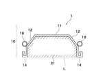
- FIG. 1A is a cross-sectional view of a steel member for foundation 1 according to the first embodiment 2 of the present invention, and FIG. 2 shows a perspective view thereof.
- the steel member for foundation 1 has a steel sheet pile 10 and a water jet pipe 18.
- the steel sheet pile 10 is integrally provided with a flange portion 12 so as to be inclined inward in the figure on both sides of the web portion 11, and a joint portion 14 is provided from the tip of the flange portion 12.
- a joint portion 14 is provided from the tip of the flange portion 12.
- one joint portion 14 and the other joint portion 14 are symmetrical to each other and are designed to have a shape opened upward in the drawing.
- This joint part 14 has a shape which can be mutually fitted with the other joint part 14 in the other adjacent steel member 1 for foundations.
- the joint portion 14 includes a portion extending in a substantially vertical direction with respect to the web portion 11 in addition to the joint having a shape that is actually symmetrical with respect to the left and right lines.
- the water jet pipe 18 is attached along the longitudinal direction A of the steel sheet pile, and is provided with a nozzle 19 for ejecting water at the first end 18a.
- the mountain side of the steel sheet pile 10 shown in FIG. 1A is defined as the outside, and the valley side is defined as the inside. That is, the water jet pipe 18 is attached on the outer side of the steel sheet pile 10.
- the water jet pipe 18 is attached in the vicinity of the boundary position between the flange portion 12 and the joint portion 14.
- the inner diameter of the water jet pipe 18 is assumed to be about 5 cm, but is not limited to this.
- the second end 18b of the water jet pipe 18 is connected to a control device and a water supply pump (not shown).
- High-pressure water sent from the water pump (not shown) is sent to the nozzle 19 through the water jet pipe 18 and is jetted through the nozzle 19.
- the ground By jetting high-pressure water through the nozzle 19, the ground can be excavated directly below the steel sheet pile 10, and can be buried in the ground with less force.
- FIG. 1B shows a cross-sectional view in a state where the lower end of the foundation steel member 1 is driven up to the underground support layer.
- the L line is a virtual line connecting the pair of joint portions 14 of the steel sheet pile 10.
- a closed cross section 31 is formed by the cross section surrounded by the steel sheet pile 10 and the L line. Due to the presence of the closed cross section 31, the earth and sand of the support layer can be compacted. Accordingly, a high vertical support force can be obtained.
- FIG. 3 shows an example in which the mounting position of the water jet pipe 18 is changed. In the modification of FIG. 3, the water jet pipe 18 is attached on the flange portion 12.
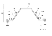
- FIG. 4A shows an example in which the shape of the steel sheet pile 10 is changed.
- the flange portion 12 is integrally provided on both sides of the web portion 11 so as to incline inward in the figure, and the joint portion 14 is provided at the tip of the flange portion 12.
- the steel sheet pile 10 has a hat-shaped cross section, and one joint portion 14 and the other joint portion 14 are symmetrical with respect to each other.
- the joint portion 14a is formed so as to face upward in the drawing
- the joint portion 14b is formed so as to face downward in the drawing.
- water jet pipes 18 are attached to the steel sheet pile 10. Two of these water jet tubes 18 are arranged on the left and right in FIG. 4A. About the left side, one each is arrange
- FIG. 4B shows an example in which the arrangement of the water jet pipe 18 is changed in the steel sheet pile 10 having a hat-shaped cross section shown in FIG. 4A. Also in this example, four water jet pipes 18 are attached to the steel sheet pile 10. Two water jet pipes 18 are arranged on the flange 12a and the flange 12b, two each on the left and right, and the water jet pipe 18 is not particularly arranged on the joint portions 14a and 14b.
- it can comprise as a steel continuous wall for foundation by mutually connecting the joint part 14 of the steel member 1 for foundations adjacent to each other.
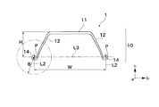
- the mounting position of the water jet pipe 18 is preferably within a range of a distance B from the joint fitting center position P of the joint portion 14 as shown in FIG. 5A.
- the joint fitting center position P here refers to the intersection of the center line L1 in the thickness direction of the arm portion 13 constituting the joint portion 14 in the hat-shaped steel sheet pile 10 and the line L2 indicating the effective width W. Defined.
- the effective width W is a distance between the fitting center positions PP of each of the pair of joint portions.
- FIG. 5B is a diagram for explaining the distance B in the steel sheet pile 10 having a U-shaped cross section.
- the joint fitting center position P is determined by the intersection of a straight line L3 parallel to the web portion 11 and at an effective height from the web portion 11 and a line L2 having an effective width W. Defined.
- the distance B is defined by the above equation (1).
- W effective width of the steel sheet pile 10
- H effective height of the steel sheet pile 10 are shown.
- the effective height H of the hat-shaped steel sheet pile 10 corresponds to the height from the bottom surface of the arm portion 13 to the top surface of the web portion 11.
- FIG. 6A shows the configuration of the press-fitting machine 4 used when press-fitting the steel member 1 for foundation by the press-fitting method.
- the press-fitting machine 4 includes a clamp 41, a saddle 42, a main cylinder 43, a mast 44, and a chuck 45.
- the clamp 41 is mounted with a mechanism for gripping the already-found foundation steel member 1.
- the clamp 41 also has a function for self-propelling on the foundation steel member 1.
- the saddle 42 is provided with a moving mechanism for moving the mast 44 in the front-rear direction, and is often equipped with a power source for the press-fitting machine 4 to perform various operations.
- the main cylinder 43 is configured to be movable in the vertical direction in the figure, and press-fits the foundation steel member 1 gripped by the chuck 45 into the ground. That is, the chuck 45 is lowered by the power of the main cylinder 43 to press-fit the base steel member 1 into the ground.
- Such a press-fitting machine 4 uses the pulling resistance force of the steel member for foundation 1 already pushed into the ground, and pushes the next steel member for foundation 1 into the ground by hydraulic pressure.
- FIG. 6B is a view of the chuck 45 in the press-fitting machine 4 as viewed from above.
- the chuck 45 can grip the joint portion 14 by pressing the joint portion 14 in the direction indicated by the arrow D3 in the drawing by the joint gripping mechanism 47.
- An opening 46 is provided inside the chuck 45.
- the opening 46 is usually set with a margin so as not to contact the web portion or the flange portion of a normal steel sheet pile.
- the interval between the opening 46 and the joint gripping mechanism 47 becomes very narrow as shown in a region H1 in FIG. 6B.
- the water jet pipe 18 is desirably provided at a position further away from the joint fitting center position P, that is, at a position away from the region H1.
- the distance B has a lower limit value of 90 mm so that the water jet pipe 18 is not positioned at this gripping portion. It is more preferable that it is within the range defined as the upper limit defined in (1).
- regulated by Formula (1) mentioned above should just be at least one.
- the reason is that the discharge of earth and sand from the joint portion 14 can be realized by the arrangement of at least one water jet pipe 18. Two or more water jet pipes 18 may be provided.
- the water jet pipe 18 As a result, the earth and sand clogged in the joint portion 14 cannot be excluded, and the ease of placing is reduced. Even when the distance B from the joint fitting center position P to the attachment position of the water jet pipe 18 is attached at a position exceeding the value on the right side of the equation (1), the placement is performed by increasing the water jet pressure. It is conceivable to ensure the ease, but this increases the construction cost and is uneconomical, and further disturbs the intermediate layer and the support layer, thereby hindering the use of the vertical support force. For this reason, in the present invention, as described above, the distance B is defined to be equal to or less than the right side of the equation (1).
- the attachment position of the water jet pipe 18 can be set closer to the joint fitting center position P.
- the distance C from the joint fitting center position P may be a range defined by the equation (2).
- the water jet pipe 18 As a result, the earth and sand clogged in the joint portion 14 cannot be excluded, and the ease of placing is reduced. Further, even when the distance B from the joint fitting center position P to the attachment position of the water jet pipe 18 is attached at a position exceeding the value on the right side of the equation (1), the water jet pressure can be increased. It is conceivable to increase the size of the vibro hammer. However, this increases the construction cost and is uneconomical. Further, the middle layer and the support layer are greatly disturbed, and the vertical support force is hindered. . Therefore, in the present invention, in the vibro hammer method, as described above, the distance C is defined to be equal to or less than the right side of the equation (2).
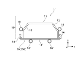
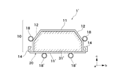
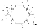
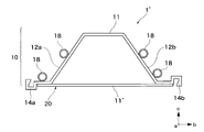
- the steel member for base 1 ′ according to the second embodiment of the present invention will be described with reference to FIGS. 7A to 9B.
- the same reference numerals are assigned to the same members in order to omit redundant description of matters described in the above-described embodiments.
- the inner side of the closing member 20 refers to the surface side which faces the closing cross-section part 31 'in the closing member 20.
- the closing member 20 is provided with respect to the joint part of the steel sheet pile 10 demonstrated in 1st Example mentioned above.
- the closing member may be provided on the flange portion. In the example shown in FIG.
- a U-shaped steel sheet pile 20U that is joined so as to be plane-symmetric with respect to the steel sheet pile 10 provided with the water jet pipe 18 is used as the closing member 20. That is, the steel member 1 'for foundations is comprised by making the steel sheet pile 10 which has a U-shaped cross section face the U-shaped steel sheet pile 20U which functions as the closing member 20, and joining these.
- a second water jet pipe 18 ′ may be provided outside the closing member 20. The position where the second water jet pipe 18 ′ is provided may be within the range described in the first embodiment.
- welding, bonding, bolts, rivets, screws, scissors, or the like may be applied.
- joining of the steel sheet pile 10 and the closing member 20 may be performed at a factory, or may be performed at the construction site before or during placement.
- a steel plate 20B may be provided as a closing member 20 for the steel sheet pile 10 having a U-shaped cross section.
- the closing member 20 may also be joined through the above-described welding or adhesion.
- FIG. 8B it is possible to form a closed section 31 'inside the steel sheet pile 10 and the steel plate 20B. Then, by pressing the base steel member 1 ′ into the ground, it becomes possible to allow the soil mass to enter the closed cross-section 31 ′. Therefore, the basic steel member 1 ′ can be firmly closed.
- a second water jet pipe may be provided outside the closing member 20 (steel plate 20B).
- the steel member 1 ′ for the foundation may be configured.
- a steel sheet pile 10 is used as a steel sheet pile 10.
- You may comprise member 1 '.
- the second water jet pipe 18 ′ can be installed on the closing member side.
- the earth lump enters the closed cross-sectional part 31' by press-fitting the base steel member 1 'into the ground. It becomes possible to make it. Therefore, the basic steel member 1 ′ can be firmly closed.
- the foundation steel member 1 is placed while water is ejected from the nozzle 19 through the water jet pipe 18 (step 1). This placement may be performed using the above-described press-fitting machine 4 or may be performed by a vibro hammer method.
- the foundation steel member 1 is placed in the intermediate layer 61. During this time, it is possible to easily place the foundation steel member 1 in the intermediate layer 61 by continuously ejecting water through the water jet pipe 18.
- Step 2 after the water jet pipe 18 ejects water until the lower end of the foundation steel member 1 approaches the vicinity of the support layer 62, the water jet pipe 18 stops the water jet.
- Step 3 the lower end of the foundation steel member 1 is penetrated into the support layer 62 while continuing the water stop.
- step 4 The placement on the support layer 62 is further continued, and the placement is completed as shown in FIG. 10D (step 4). Until this completion, the ejection of water by the water jet pipe 18 remains stopped.
- FIG. 11A to FIG. 11D show another placing method of the steel member for the foundation to which the present invention is applied.
- the foundation steel member 1 is placed while water is ejected from the nozzle 19 through the water jet pipe 18 (step 1 ').
- FIG. 11B after water is ejected by the water jet pipe 18 until the lower end of the basic steel member 1 approaches the vicinity of the support layer 62, the water jet pressure of the water jet in the water jet pipe 18 Is reduced to reduce water ejection (step 2 ').
- FIG. 11B shows after water is ejected by the water jet pipe 18 until the lower end of the basic steel member 1 approaches the vicinity of the support layer 62.
- step 3 the lower end of the foundation steel member 1 is penetrated into the support layer 62 while the water ejection is weakened.
- the placement on the support layer 62 is further continued, and the placement is completed as shown in FIG. 11D (step 4 '). Until the completion, the jet of water through the water jet pipe 18 is stopped, or the water jet pressure of the water jet is reduced.
- FIG. 12 shows a specific example in the case where the water jet is stopped or weakened by the water jet pipe 18.
- the water jet is stopped until the lower end of the foundation steel member 1 placed in the ground (intermediate layer 61) reaches the support layer from 3 m above the support layer 62, or Reduce water jet pressure. Then, from the time of reduction until the end of placing, the water jet stop or jetting of water by the water jet pipe 18 is continued to be weakened.
- the depth from the upper end of the support layer 62 at the lower end of the foundation steel member 1 at the end of the placement is ⁇ m
- the operation of stopping or weakening the ejection of water by the water jet pipe 18 is (3 + ⁇ ) It will continue to run for m.
- the water jet is stopped until the lower end of the foundation steel member 1 press-fitted into the ground (intermediate layer 61) reaches the support layer from 1 m above the support layer 62,
- the water ejection pressure may be reduced and then continued until the end of placement.
- the operation to stop or weaken the ejection of water by the water jet pipe 18 is continuously performed for (1 + ⁇ ) m.
- the water jet is stopped until the lower end of the foundation steel member 1 placed in the ground (intermediate layer 61) reaches the support layer 62 from 1 to 3 m above the support layer 62. Or reduce the water jet pressure. Thereby, it is possible to prevent the support layer 62 from being disturbed by the ejection of water through the water jet pipe 18. And by embedding the base steel member 1 in the support layer 62 in an undisturbed state, when applied to a foundation structure that supports the structure in the vertical direction, a high vertical support force can be exhibited. It becomes possible.
- the water jet pipe 18 continues to eject water until just before the lower end of the base steel member 1 reaches the support layer 62.
- excavation in the intermediate layer 61 can be performed very easily.
- the workability by the water jet is improved when the foundation steel member 1 is placed in the ground by using the jet by the water jet together. At the same time, it is possible to reliably form the tip closing portion and to exert a vertical supporting force.
- the water jet pressure by the water jet pipe 18 is often applied at a pressure of 10 MPa or more.
- the water jet pressure is set to half of 10 MPa, that is, 5 MPa or less. Therefore, while suppressing disturbance of the support layer 61, it is possible to facilitate the rise of the water jet pressure again by preventing the entry of earth and sand into the nozzle 19, and further, the support force at the lower end portion of the foundation steel member 1 is increased. It can be secured.
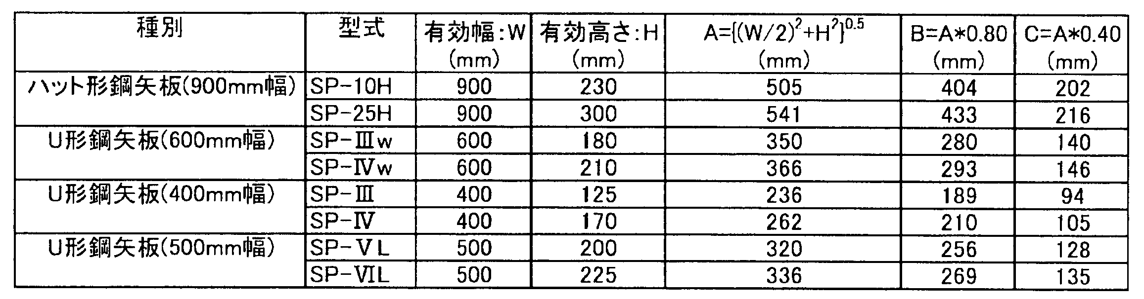
- Table 1 shows the effective width W, the effective height H, and the distances B and C calculated based on the formulas (1) and (2) for each model in the steel member for foundation 1 to which the present invention is applied. Show. In Table 1, ⁇ (W / 2) 2 + H 2 ⁇ 1/2 on the right side of the expressions (1) and (2) is A.
- the workability by the water jet is improved and the tip closing portion is reliably formed to exert the vertical support force. It is possible to provide a foundation steel member, a foundation steel member placement method, and a foundation steel continuous wall. Therefore, industrial applicability is great.
Landscapes
- Engineering & Computer Science (AREA)
- Structural Engineering (AREA)
- Chemical & Material Sciences (AREA)
- Composite Materials (AREA)
- Life Sciences & Earth Sciences (AREA)
- General Life Sciences & Earth Sciences (AREA)
- Mining & Mineral Resources (AREA)
- Paleontology (AREA)
- Civil Engineering (AREA)
- General Engineering & Computer Science (AREA)
- Bulkheads Adapted To Foundation Construction (AREA)
- Placing Or Removing Of Piles Or Sheet Piles, Or Accessories Thereof (AREA)
Abstract
Description
本願は、2009年2月4日に、日本に出願された特願2009-023655号に基づき優先権を主張し、その内容をここに援用する。
(1)本発明の第1の態様は、ウェブ部と、前記ウェブ部の両端に連設される一対のフランジ部と、前記一対のフランジ部の側端部に設けられる一対の継手部と、を有する鋼矢板と; 前記鋼矢板の外側のみにおいて、前記鋼矢板の長手方向に沿って取り付けられる第1のウォータージェット管と;を備える基礎用鋼製部材である。
(2)上記(1)に記載の基礎用鋼製部材では、前記第1のウォータージェット管が、Bを前記継手部の継手嵌合中心位置からの距離、Wを前記鋼矢板の有効幅、Hを前記鋼矢板の有効高さとして、

(3)上記(1)又は(2)に記載の基礎用鋼製部材は、前記鋼矢板の内側に接合する両端部を有する閉合部材を更に備えてもよい。
(4)上記(3)に記載の基礎用鋼製部材では、前記閉合部材の外側のみにおいて前記閉合部材の長手方向に沿って設けられる第2のウォータージェット管を更に備えてもよい。
(5)上記(4)に記載の基礎用鋼製部材では、前記第2のウォータージェット管が、Bを前記継手部の継手嵌合中心位置からの距離、Wを前記鋼矢板の有効幅、Hを前記鋼矢板の有効高さとして、

(6)上記(1)又は(2)に記載の基礎用鋼製部材は、前記第1のウォータージェット管の噴出出力を制御する制御装置を更に備えてもよい。
(7)上記(6)に記載の基礎用鋼製部材では、前記制御装置は、地中に圧入した前記基礎用鋼製部材の下端が、支持層の1~3m上から前記支持層に到達するまでに、前記ウォータージェットの水噴出圧力を5MPa以下に低減させるように制御してもよい。
(8)上記(1)又は(2)に記載の基礎用鋼製部材では、前記第1のウォータージェット管の下端部が、鉛直下向きに液体を噴出可能なノズルを更に備えてもよい。
(9)本発明の第2の態様は、上記(1)又は(2)に記載の基礎用鋼製部材を地中に打設する基礎用鋼製部材の打設方法である。この打設方法は、前記ウォータージェットから水を噴出させながら前記基礎用鋼製部材を前記地中に埋め込む工程と;前記基礎用鋼製部材の下端が、前記地中の支持層の1~3m上から前記支持層に到達するまでに、前記水の噴出を停止させる工程と;を備える。
(10)本発明の第3の態様は、上記(1)又は(2)に記載の基礎用鋼製部材を地中に打設する基礎用鋼製部材の打設方法である。この打設方法は、前記ウォータージェット管から水を噴出させながら前記基礎用鋼製部材を前記地中に埋め込む工程と;前記基礎用鋼製部材の下端が、前記地中の支持層の1~3m上から前記支持層に到達するまでに、前記ウォータージェット管からの水噴出圧力を5MPa以下に低減させる工程と;を備える。
(11)上記(10)に記載の基礎用鋼製部材の打設方法は、前記水噴出圧力を5MPa以下に低減させる工程の後に、前記ウォータージェット管からの水噴出圧力が2.5MPa以上5MPa以下に保持する工程を更に備えてもよい。
(12)本発明の第4の態様は、上記(1)又は(2)に記載の少なくとも2つの基礎用鋼製部材を互いの継手部で連結して構成される基礎用鋼製連続壁であり、前記少なくとも2つの基礎用鋼製部材の下端が支持層まで貫入される。
(13)本発明の第5の態様は、上記(1)又は(2)に記載の少なくとも2つの基礎用鋼製部材を互いの継手部で連結して構成される基礎用鋼製連続壁であり、前記少なくとも2つの基礎用鋼製部材は、下端が中間層まで貫入される第1の基礎用鋼製部材と、下端が支持層まで貫入される第2の基礎用鋼製部材とを含む。
上記(2)に記載の本発明の構成によれば、第1のウォータージェット管が所定の距離Bの範囲内に取り付けられるため、第1のウォータージェット管による噴出により、特に継手部に詰まった土砂を排除することが可能となる。このため、高い鉛直支持力と打設容易性を発揮することができる。
上記(3)に記載の本発明の構成によれば、鋼矢板の断面と閉合部材の断面とで囲まれる断面閉塞部が形成されるため、更に確実に鉛直支持力を発揮することができる。
上記(4)に記載の本発明の構成によれば、第2のウォータージェット管が閉合部材の外側に取り付けられるため、高い鉛直支持力と打設容易性とを発揮することができる。
上記(5)に記載の本発明の構成によれば、更に高い打設容易性を発揮することができる。
上記(6)~(8)に記載の本発明の構成によれば、高い鉛直支持力と打設容易性とを発揮することができる。
上記(11)に記載の本発明の構成によれば、上記(10)の構成による場合よりも確実に高い鉛直支持力を発揮させることができる。
上記(12)に記載の本発明の構成によれば、上記(1)~(2)の構成による基礎用鋼製部材を連ねるため、高い鉛直支持力を有する連続壁を得ることができる。
上記(13)に記載の本発明の構成によれば、上記(1)~(2)の構成による基礎用鋼製部材のみで連続壁を形成する場合と比べて安価且つ容易に、高い鉛直支持力を有する連続壁を得ることができる。

(第1実施形態)

(第2実施形態)
第2の実施形態においては、前述した第1実施例で説明した鋼矢板10の継手部に対し、閉合部材20が設けられる。なお、閉合部材はフランジ部に設けられてもよい。図7Aに示す例では、閉合部材20として、ウォータージェット管18が設けられた鋼矢板10に対して面対称となるように接合される断面U形鋼矢板20Uが用いられている。即ち、断面U形を有する鋼矢板10に、閉合部材20として機能する断面U形鋼矢板20Uを対面させて、これらを接合することにより、基礎用鋼製部材1’が構成される。この閉合部材20の外側に第2のウォータージェット管18’を設けてもよい。第2のウォータージェット管18’を設ける位置は、上述した第1の実施形態において説明した範囲内であってもよい。これらの鋼矢板10と閉合部材20との接合は、例えば、溶接、接着、ボルト、リベット、ビス、鋲等の何れかを適用してもよい。また、鋼矢板10と閉合部材20との接合は、工場で行ってもよいし、施工現場で打設前あるいは打設時に行ってもよい。
10 鋼矢板
11 ウェブ部
12 フランジ部
14 継手部
18 ウォータージェット管
19 ノズル
Claims (13)
- ウェブ部と、前記ウェブ部の両端に連設される一対のフランジ部と、前記一対のフランジ部の側端部に設けられる一対の継手部と、を有する鋼矢板と;
前記鋼矢板の外側のみにおいて、前記鋼矢板の長手方向に沿って取り付けられる第1のウォータージェット管と;
を備えることを特徴とする基礎用鋼製部材。 - 前記第1のウォータージェット管が、Bを前記継手部の継手嵌合中心位置からの距離、Wを前記鋼矢板の有効幅、Hを前記鋼矢板の有効高さとして、
を満たすように設けられていることを特徴とする請求項1に記載の基礎用鋼製部材。
- 前記鋼矢板の内側に接合する両端部を有する閉合部材を更に備えることを特徴とする請求項1又は2に記載の基礎用鋼製部材。
- 前記閉合部材の外側のみにおいて前記閉合部材の長手方向に沿って設けられる第2のウォータージェット管を更に備えることを特徴とする請求項3に記載の基礎用鋼製部材。
- 前記第2のウォータージェット管が、Bを前記継手部の継手嵌合中心位置からの距離、Wを前記鋼矢板の有効幅、Hを前記鋼矢板の有効高さとして、
を満たすように設けられていることを特徴とする請求項4に記載の基礎用鋼製部材。
- 前記第1のウォータージェット管の噴出出力を制御する制御装置を更に備えることを特徴とする請求項1又は2に記載の基礎用鋼製部材。
- 前記制御装置は、地中に圧入した前記基礎用鋼製部材の下端が、支持層の1~3m上から前記支持層に到達するまでに、前記ウォータージェットの水噴出圧力を5MPa以下に低減させるように制御することを特徴とする請求項6に記載の基礎用鋼製部材。
- 前記第1のウォータージェット管の下端部が、鉛直下向きに液体を噴出可能なノズルを更に備えることを特徴とする請求項1又は2に記載の基礎用鋼製部材。
- 請求項1又は2に記載の基礎用鋼製部材を地中に打設する基礎用鋼製部材の打設方法であって、
前記ウォータージェット管から水を噴出させながら前記基礎用鋼製部材を前記地中に埋め込む工程と;
前記基礎用鋼製部材の下端が、前記地中の支持層の1~3m上から前記支持層に到達するまでに、前記水の噴出を停止させる工程と;
を備えることを特徴とする基礎用鋼製部材の打設方法。 - 請求項1又は2に記載の基礎用鋼製部材を地中に打設する基礎用鋼製部材の打設方法であって、
前記ウォータージェット管から水を噴出させながら前記基礎用鋼製部材を前記地中に埋め込む工程と;
前記基礎用鋼製部材の下端が、前記地中の支持層の1~3m上から前記支持層に到達するまでに、前記ウォータージェット管からの水噴出圧力を5MPa以下に低減させる工程と;
を備えることを特徴とする基礎用鋼製部材の打設方法。 - 前記水噴出圧力を5MPa以下に低減させる工程の後に、前記ウォータージェット管からの水噴出圧力が2.5MPa以上5MPa以下に保持する工程を更に備えることを特徴とする請求項10に記載の基礎用鋼製部材の打設方法。
- 請求項1又は2に記載の少なくとも2つの基礎用鋼製部材を互いの継手部で連結して構成される基礎用鋼製連続壁であって、
前記少なくとも2つの基礎用鋼製部材の下端が支持層まで貫入されることを特徴とする基礎用鋼製連続壁。 - 請求項1又は2に記載の少なくとも2つの基礎用鋼製部材を互いの継手部で連結して構成される基礎用鋼製連続壁であって、 前記少なくとも2つの基礎用鋼製部材は、下端が中間層まで貫入される第1の基礎用鋼製部材と、下端が支持層まで貫入される第2の基礎用鋼製部材とを含むことを特徴とする基礎用鋼製連続壁。
Priority Applications (2)
| Application Number | Priority Date | Filing Date | Title |
|---|---|---|---|
| JP2010549386A JP4885313B2 (ja) | 2009-02-04 | 2010-02-01 | 基礎用鋼製部材、基礎用鋼製部材の打設方法、及び基礎用鋼製連続壁 |
| CN2010800038314A CN102272384A (zh) | 2009-02-04 | 2010-02-01 | 基础用钢制部件、基础用钢制部件的打设方法以及基础用钢制连续壁 |
Applications Claiming Priority (2)
| Application Number | Priority Date | Filing Date | Title |
|---|---|---|---|
| JP2009023655 | 2009-02-04 | ||
| JP2009-023655 | 2009-02-04 |
Publications (1)
| Publication Number | Publication Date |
|---|---|
| WO2010089985A1 true WO2010089985A1 (ja) | 2010-08-12 |
Family
ID=42541896
Family Applications (1)
| Application Number | Title | Priority Date | Filing Date |
|---|---|---|---|
| PCT/JP2010/000577 Ceased WO2010089985A1 (ja) | 2009-02-04 | 2010-02-01 | 基礎用鋼製部材、基礎用鋼製部材の打設方法、及び基礎用鋼製連続壁 |
Country Status (4)
| Country | Link |
|---|---|
| JP (1) | JP4885313B2 (ja) |
| CN (1) | CN102272384A (ja) |
| TW (1) | TW201033442A (ja) |
| WO (1) | WO2010089985A1 (ja) |
Cited By (6)
| Publication number | Priority date | Publication date | Assignee | Title |
|---|---|---|---|---|
| JP2013155570A (ja) * | 2012-01-31 | 2013-08-15 | Sumitomo Forestry Co Ltd | 液状化抑制構造 |
| JP2013163901A (ja) * | 2012-02-09 | 2013-08-22 | Sumitomo Forestry Co Ltd | 鋼板地中隔壁の形成方法 |
| JP2013204273A (ja) * | 2012-03-28 | 2013-10-07 | Nippon Steel & Sumitomo Metal | 鋼矢板基礎の施工方法及び鋼矢板基礎 |
| JP2015145558A (ja) * | 2014-01-31 | 2015-08-13 | ミツワ興業株式会社 | 矢板用管体配設装置及び矢板への管体配設方法 |
| JP2015229843A (ja) * | 2014-06-04 | 2015-12-21 | 新日鐵住金株式会社 | 先端加工鋼矢板及びその打設方法 |
| EP4089235A1 (en) * | 2021-05-11 | 2022-11-16 | Ørsted Wind Power A/S | A method of installing a foundation and a foundation for a structure |
Families Citing this family (2)
| Publication number | Priority date | Publication date | Assignee | Title |
|---|---|---|---|---|
| TWI510695B (zh) * | 2012-07-16 | 2015-12-01 | Jfe Steel Corp | 帽型鋼板樁 |
| JP7569049B2 (ja) * | 2020-10-26 | 2024-10-17 | 日本製鉄株式会社 | 鋼矢板および鋼矢板の施工方法 |
Citations (7)
| Publication number | Priority date | Publication date | Assignee | Title |
|---|---|---|---|---|
| JPS5478813A (en) * | 1977-12-07 | 1979-06-23 | Kawasaki Steel Co | Method of construction of combination steel sheet pile |
| JPH11350484A (ja) * | 1998-06-04 | 1999-12-21 | Giken Seisakusho Co Ltd | 鋼管杭のウォータジェット工法及び同工法用の杭圧入引抜機 |
| JP2002129561A (ja) * | 2000-10-23 | 2002-05-09 | Tomec Corp | 圧力水噴射併用振動打込み杭工法 |
| JP2008057171A (ja) * | 2006-08-30 | 2008-03-13 | Giken Seisakusho Co Ltd | 鋼矢板用圧入機 |
| JP2008069631A (ja) * | 2007-11-30 | 2008-03-27 | Nippon Steel Corp | ハット型鋼矢板およびその形状設定方法 |
| JP2008175029A (ja) * | 2007-01-22 | 2008-07-31 | Nippon Steel Corp | 地中連続壁体用鋼製部材、地中連続壁体 |
| JP2008248503A (ja) * | 2007-03-29 | 2008-10-16 | Nippon Steel Corp | 鋼矢板および鋼矢板基礎構造 |
-
2010
- 2010-02-01 CN CN2010800038314A patent/CN102272384A/zh active Pending
- 2010-02-01 WO PCT/JP2010/000577 patent/WO2010089985A1/ja not_active Ceased
- 2010-02-01 JP JP2010549386A patent/JP4885313B2/ja active Active
- 2010-02-02 TW TW99103000A patent/TW201033442A/zh unknown
Patent Citations (7)
| Publication number | Priority date | Publication date | Assignee | Title |
|---|---|---|---|---|
| JPS5478813A (en) * | 1977-12-07 | 1979-06-23 | Kawasaki Steel Co | Method of construction of combination steel sheet pile |
| JPH11350484A (ja) * | 1998-06-04 | 1999-12-21 | Giken Seisakusho Co Ltd | 鋼管杭のウォータジェット工法及び同工法用の杭圧入引抜機 |
| JP2002129561A (ja) * | 2000-10-23 | 2002-05-09 | Tomec Corp | 圧力水噴射併用振動打込み杭工法 |
| JP2008057171A (ja) * | 2006-08-30 | 2008-03-13 | Giken Seisakusho Co Ltd | 鋼矢板用圧入機 |
| JP2008175029A (ja) * | 2007-01-22 | 2008-07-31 | Nippon Steel Corp | 地中連続壁体用鋼製部材、地中連続壁体 |
| JP2008248503A (ja) * | 2007-03-29 | 2008-10-16 | Nippon Steel Corp | 鋼矢板および鋼矢板基礎構造 |
| JP2008069631A (ja) * | 2007-11-30 | 2008-03-27 | Nippon Steel Corp | ハット型鋼矢板およびその形状設定方法 |
Cited By (8)
| Publication number | Priority date | Publication date | Assignee | Title |
|---|---|---|---|---|
| JP2013155570A (ja) * | 2012-01-31 | 2013-08-15 | Sumitomo Forestry Co Ltd | 液状化抑制構造 |
| JP2013163901A (ja) * | 2012-02-09 | 2013-08-22 | Sumitomo Forestry Co Ltd | 鋼板地中隔壁の形成方法 |
| JP2013204273A (ja) * | 2012-03-28 | 2013-10-07 | Nippon Steel & Sumitomo Metal | 鋼矢板基礎の施工方法及び鋼矢板基礎 |
| JP2015145558A (ja) * | 2014-01-31 | 2015-08-13 | ミツワ興業株式会社 | 矢板用管体配設装置及び矢板への管体配設方法 |
| JP2015229843A (ja) * | 2014-06-04 | 2015-12-21 | 新日鐵住金株式会社 | 先端加工鋼矢板及びその打設方法 |
| EP4089235A1 (en) * | 2021-05-11 | 2022-11-16 | Ørsted Wind Power A/S | A method of installing a foundation and a foundation for a structure |
| WO2022238332A1 (en) * | 2021-05-11 | 2022-11-17 | Ørstedwindpower A/S | A method of installing a foundation and a foundation for a structure |
| US12584284B2 (en) | 2021-05-11 | 2026-03-24 | Ørsted Wind Power A/S | Method of installing a foundation and a foundation for a structure |
Also Published As
| Publication number | Publication date |
|---|---|
| JPWO2010089985A1 (ja) | 2012-08-09 |
| JP4885313B2 (ja) | 2012-02-29 |
| TW201033442A (en) | 2010-09-16 |
| CN102272384A (zh) | 2011-12-07 |
Similar Documents
| Publication | Publication Date | Title |
|---|---|---|
| JP4885313B2 (ja) | 基礎用鋼製部材、基礎用鋼製部材の打設方法、及び基礎用鋼製連続壁 | |
| CN102159769B (zh) | 钢管板桩、钢管板桩的接头构造和壁构造、以及钢管板桩的拉拔方法 | |
| JP5495706B2 (ja) | 既設港湾岸壁の補強構造 | |
| JP6093923B2 (ja) | 鋼管杭及び鋼管杭の施工法 | |
| TW201139791A (en) | Steel wall and construction method for steel wall | |
| JP7017541B2 (ja) | 既存矢板式岸壁の改良構造及び改良方法 | |
| EP2848739A1 (en) | Steel wall | |
| CN105672316A (zh) | 钢桩下沉减阻装置及施工方法 | |
| CN205591205U (zh) | 一种钢板桩基坑支护结构 | |
| JP3733533B2 (ja) | 既存構造物の被圧水下の基礎補強方法 | |
| JP2009167734A (ja) | 耐震補強工事における補強鋼板の地中貫入方法及び補強鋼板貫入装置 | |
| JP2015052212A (ja) | 桟橋構築方法および鋼管杭施工方法 | |
| JP2014051820A (ja) | 組合せ鋼製壁 | |
| JPWO2010089966A1 (ja) | 組合せ鋼矢板、組合せ鋼矢板を利用した連続壁、及び組合せ鋼矢板の圧入方法 | |
| JP2013177787A (ja) | 鋼管矢板基礎の施工法 | |
| JP5471381B2 (ja) | 盛土の補強工法 | |
| JP2006200174A (ja) | 橋脚等の補強工法およびその補強装置 | |
| JP3871937B2 (ja) | 水中骨組構造物の施工方法 | |
| JP2007297826A (ja) | 橋脚の鋼板を用いた補強方法 | |
| HK1161322A (en) | Steel member for foundation, method of driving steel member for foundation, and continuous steel wall for foundation | |
| JP2019056231A (ja) | 岸壁構造 | |
| JP6138192B2 (ja) | 鋼管杭施工方法 | |
| JP3870146B2 (ja) | 岩盤への杭打用杭とその杭打工法 | |
| KR0149397B1 (ko) | 무용접 장대 강판 말뚝 및 그 시공방법 | |
| JP2022175684A (ja) | 土留壁 |
Legal Events
| Date | Code | Title | Description |
|---|---|---|---|
| WWE | Wipo information: entry into national phase |
Ref document number: 201080003831.4 Country of ref document: CN |
|
| 121 | Ep: the epo has been informed by wipo that ep was designated in this application |
Ref document number: 10738328 Country of ref document: EP Kind code of ref document: A1 |
|
| ENP | Entry into the national phase |
Ref document number: 2010549386 Country of ref document: JP Kind code of ref document: A |
|
| NENP | Non-entry into the national phase |
Ref country code: DE |
|
| 122 | Ep: pct application non-entry in european phase |
Ref document number: 10738328 Country of ref document: EP Kind code of ref document: A1 |