WO2010087448A1 - 画像形成装置 - Google Patents
画像形成装置 Download PDFInfo
- Publication number
- WO2010087448A1 WO2010087448A1 PCT/JP2010/051263 JP2010051263W WO2010087448A1 WO 2010087448 A1 WO2010087448 A1 WO 2010087448A1 JP 2010051263 W JP2010051263 W JP 2010051263W WO 2010087448 A1 WO2010087448 A1 WO 2010087448A1
- Authority
- WO
- WIPO (PCT)
- Prior art keywords
- nip portion
- transfer
- image forming
- secondary transfer
- speed
- Prior art date
- Legal status (The legal status is an assumption and is not a legal conclusion. Google has not performed a legal analysis and makes no representation as to the accuracy of the status listed.)
- Ceased
Links
Images





Classifications
-
- G—PHYSICS
- G03—PHOTOGRAPHY; CINEMATOGRAPHY; ANALOGOUS TECHNIQUES USING WAVES OTHER THAN OPTICAL WAVES; ELECTROGRAPHY; HOLOGRAPHY
- G03G—ELECTROGRAPHY; ELECTROPHOTOGRAPHY; MAGNETOGRAPHY
- G03G15/00—Apparatus for electrographic processes using a charge pattern
- G03G15/65—Apparatus which relate to the handling of copy material
- G03G15/6555—Handling of sheet copy material taking place in a specific part of the copy material feeding path
- G03G15/657—Feeding path after the transfer point and up to the fixing point, e.g. guides and feeding means for handling copy material carrying an unfused toner image
-
- G—PHYSICS
- G03—PHOTOGRAPHY; CINEMATOGRAPHY; ANALOGOUS TECHNIQUES USING WAVES OTHER THAN OPTICAL WAVES; ELECTROGRAPHY; HOLOGRAPHY
- G03G—ELECTROGRAPHY; ELECTROPHOTOGRAPHY; MAGNETOGRAPHY
- G03G15/00—Apparatus for electrographic processes using a charge pattern
- G03G15/01—Apparatus for electrographic processes using a charge pattern for producing multicoloured copies
- G03G15/0105—Details of unit
- G03G15/0131—Details of unit for transferring a pattern to a second base
-
- G—PHYSICS
- G03—PHOTOGRAPHY; CINEMATOGRAPHY; ANALOGOUS TECHNIQUES USING WAVES OTHER THAN OPTICAL WAVES; ELECTROGRAPHY; HOLOGRAPHY
- G03G—ELECTROGRAPHY; ELECTROPHOTOGRAPHY; MAGNETOGRAPHY
- G03G15/00—Apparatus for electrographic processes using a charge pattern
- G03G15/14—Apparatus for electrographic processes using a charge pattern for transferring a pattern to a second base
- G03G15/16—Apparatus for electrographic processes using a charge pattern for transferring a pattern to a second base of a toner pattern, e.g. a powder pattern, e.g. magnetic transfer
- G03G15/1605—Apparatus for electrographic processes using a charge pattern for transferring a pattern to a second base of a toner pattern, e.g. a powder pattern, e.g. magnetic transfer using at least one intermediate support
-
- G—PHYSICS
- G03—PHOTOGRAPHY; CINEMATOGRAPHY; ANALOGOUS TECHNIQUES USING WAVES OTHER THAN OPTICAL WAVES; ELECTROGRAPHY; HOLOGRAPHY
- G03G—ELECTROGRAPHY; ELECTROPHOTOGRAPHY; MAGNETOGRAPHY
- G03G15/00—Apparatus for electrographic processes using a charge pattern
- G03G15/20—Apparatus for electrographic processes using a charge pattern for fixing, e.g. by using heat
- G03G15/2003—Apparatus for electrographic processes using a charge pattern for fixing, e.g. by using heat using heat
- G03G15/2014—Apparatus for electrographic processes using a charge pattern for fixing, e.g. by using heat using heat using contact heat
- G03G15/2017—Structural details of the fixing unit in general, e.g. cooling means, heat shielding means
- G03G15/2028—Structural details of the fixing unit in general, e.g. cooling means, heat shielding means with means for handling the copy material in the fixing nip, e.g. introduction guides, stripping means
-
- G—PHYSICS
- G03—PHOTOGRAPHY; CINEMATOGRAPHY; ANALOGOUS TECHNIQUES USING WAVES OTHER THAN OPTICAL WAVES; ELECTROGRAPHY; HOLOGRAPHY
- G03G—ELECTROGRAPHY; ELECTROPHOTOGRAPHY; MAGNETOGRAPHY
- G03G2215/00—Apparatus for electrophotographic processes
- G03G2215/00362—Apparatus for electrophotographic processes relating to the copy medium handling
- G03G2215/00367—The feeding path segment where particular handling of the copy medium occurs, segments being adjacent and non-overlapping. Each segment is identified by the most downstream point in the segment, so that for instance the segment labelled "Fixing device" is referring to the path between the "Transfer device" and the "Fixing device"
- G03G2215/00413—Fixing device
-
- G—PHYSICS
- G03—PHOTOGRAPHY; CINEMATOGRAPHY; ANALOGOUS TECHNIQUES USING WAVES OTHER THAN OPTICAL WAVES; ELECTROGRAPHY; HOLOGRAPHY
- G03G—ELECTROGRAPHY; ELECTROPHOTOGRAPHY; MAGNETOGRAPHY
- G03G2215/00—Apparatus for electrophotographic processes
- G03G2215/01—Apparatus for electrophotographic processes for producing multicoloured copies
- G03G2215/0151—Apparatus for electrophotographic processes for producing multicoloured copies characterised by the technical problem
- G03G2215/0158—Colour registration
Definitions
- the present invention relates to an image forming apparatus for forming an image on a transfer material by an electrophotographic method.
- image forming apparatuses such as laser printers and copiers are required to have high speed and high image quality. Therefore, in the image forming apparatus, a toner image formed on an image carrier such as a photosensitive drum is transferred to an intermediate transfer member such as a belt, and then the toner image is transferred from the intermediate transfer member to a transfer material such as a sheet. Is often adopted.
- Tandem-type full-color machines are widely used as image forming apparatuses capable of forming color images at high speed and high image quality.
- image forming apparatuses capable of forming color images at high speed and high image quality.
- four image forming units of yellow (Y), magenta (M), cyan (C), and black (Bk) are arranged in parallel, and the photosensitive drum of the image forming unit contacts an intermediate transfer belt that is an intermediate transfer member. This is the configuration.
- the intermediate transfer belt is pressed against and brought into contact with the photosensitive drum.
- an image forming apparatus capable of forming a full-color image has a full-color mode in which the image forming units of all colors function while all the photosensitive drums are in contact with the intermediate transfer belt. Further, there may be two mono-color modes in which at least one (for example, black) image forming unit functions while at least one photosensitive drum and the intermediate transfer belt are separated from each other.
- the purpose of providing these two modes is mainly to extend the life of the photosensitive drum of the image forming unit and to reduce toner consumption.
- the mono color mode using only black it is possible to prevent the photosensitive drum surface from being worn and to extend the life of the photosensitive drum by preventing the photosensitive drum of the image forming unit that does not function and the intermediate transfer belt from contacting each other.
- the rotation of the photosensitive drum is stopped, so there is no need to use toner as a lubricant for preventing the blade from turning up, and the toner consumption is reduced. It is possible to reduce the amount.
- the mono-color mode has a smaller number of photosensitive drums in contact with the intermediate transfer belt than the full-color mode. That is, there are few restraining points for clamping the intermediate transfer belt between the photosensitive drum and the primary transfer member, and the clamping force for the intermediate transfer belt is reduced.
- the mono-color mode in which the holding force of the belt is reduced the leading edge of the sheet as the transfer material enters the secondary transfer nip portion formed by the intermediate transfer belt and the secondary transfer member, or the trailing edge is When it comes off, the load on the intermediate transfer belt fluctuates.
- the load fluctuations generated in this way may affect the drive member that drives the intermediate transfer belt, and may change the speed of the intermediate transfer belt.
- a density difference occurs in the toner image being transferred at the primary transfer nip due to the influence of the speed fluctuation in the intermediate transfer belt.
- Patent Document 1 proposes a configuration in which the pressing force against the intermediate transfer belt of the primary transfer member that contacts the intermediate transfer belt in the mono color mode is larger than the pressing force in the full color mode in the full color mode and the mono color mode. ing.
- the present invention has been made paying attention to the above points, and suppresses fluctuations in the speed of the intermediate transfer belt that occur when the transfer material comes out of the secondary transfer nip formed by the secondary transfer member and the intermediate transfer belt.
- An object of the present invention is to provide an image forming apparatus capable of obtaining a high-quality image.
- the present invention provides a rotatable intermediate transfer belt, a plurality of image carriers that are arranged in a rotation direction of the intermediate transfer belt, and that carries a toner image, and the plurality of image carriers.
- a plurality of primary transfer members that are opposed to each other via the intermediate transfer belt and can form a primary transfer nip portion with the opposing image carrier, and transfer to the intermediate transfer belt by the primary transfer member
- a secondary transfer member that transfers the toner image transferred to the transfer material at the secondary transfer nip
- a fixing unit that fixes the toner image transferred by the secondary transfer member to the transfer material at the fixing nip
- the secondary A primary control member that controls a transfer speed of the transfer material in the transfer nip portion and a speed control circuit that controls a transfer speed of the transfer material in the fixing nip portion, and the primary transfer member and the primary transfer that each of the plurality of image carriers face each other.
- a first image forming mode in which image formation is performed in a state where a nip portion is formed, and the primary transfer member and the primary transfer nip portion at least one of the plurality of image carriers facing each other are formed.
- the speed control circuit includes the secondary transfer nip portion when the second image forming mode is executed.
- the loop amount of the transfer material between the fixing nip portion is larger than the loop amount of the transfer material between the secondary transfer nip portion and the fixing nip portion when the first image forming mode is executed.
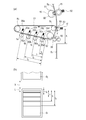
- FIG. 1 schematically shows an image forming apparatus according to the present invention.
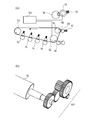
- the figure explaining the speed control circuit and drive part which concern on this invention The figure explaining the positional relationship between the secondary transfer nip portion and the primary transfer nip portion when executing the second image forming mode and the second image forming mode.
- FIG. 6 is a diagram illustrating an outline of an intermediate transfer nip portion according to a second embodiment.
- the image forming apparatus has a configuration of a color laser printer (hereinafter referred to as a printer unit) 100 as a main body of the image forming apparatus, and FIG. 1 is a longitudinal sectional view showing the overall configuration.
- a printer unit a color laser printer
- the printer unit 100 shown in FIG. 1 includes process cartridges 3a, 3b, 3c, and 3d that are detachable from the apparatus main body. These four process cartridges 3a, 3b, 3c, and 3d have the same structure, but images of toners of different colors, that is, yellow (Y), magenta (M), cyan (C), and black (Bk) are displayed. It differs in the point to form.
- the process cartridges 3a, 3b, 3c, 3d have developing units 4a, 4b, 4c, 4d and cleaner units 5a, 5b, 5c, 5d.
- the developing units 4a, 4b, 4c, and 4d include developing rollers 6a, 6b, 6c, and 6d, developer application rollers 7a, 7b, 7c, and 7d, and a toner container.
- the cleaner units 5a, 5b, 5c and 5d are photosensitive drums 1a, 1b, 1c and 1d which are image carriers, charging rollers 2a, 2b, 2c and 2d, and drum cleaning blades 8a, 8b, 8c and 8d. And a waste toner container.
- a scanner unit 9 is arranged vertically below the process cartridges 3a, 3b, 3c, 3d, and exposes the photosensitive drums 1a, 1b, 1c, 1d based on image signals.
- the photosensitive drums 1a, 1b, 1c, and 1d are charged to a predetermined negative potential by the charging rollers 2a, 2b, 2c, and 2d, and then electrostatic latent images are formed by the scanner unit 9, respectively.
- the electrostatic latent image is attached with negative toner by developing units 4a, 4b, 4c, and 4d, and Y, M, C, and Bk toner images are developed.
- the intermediate transfer belt unit 10 includes a driving roller 52, a tension roller 53, a secondary transfer counter roller 54, primary transfer rollers 50a to 50d, and an intermediate transfer belt 51.
- the primary transfer rollers 50a to 50d are primary transfer members.
- An endless intermediate transfer belt 51 as an intermediate transfer member is stretched around a driving roller 52, a tension roller 53, and a secondary transfer counter roller 54 as stretch rollers.
- the intermediate transfer belt can be rotated as the driving roller 52 rotates.
- the tension roller 53 applies tension (in the direction of arrow T) from the inner side to the outer side of the intermediate transfer belt 51.
- primary transfer rollers 50a, 50b, 50c, and 50d which are primary transfer members, are installed on the inner surface side of the intermediate transfer belt 51 so as to face the photosensitive drums 1a, 1b, 1c, and 1d.
- a transfer voltage is applied to the primary transfer rollers 50a, 50b, 50c, and 50d by a bias applying unit (not shown).
- Each primary transfer roller can form a primary transfer nip portion with each photosensitive drum opposed via the intermediate transfer belt.
- the photosensitive drums 1 a, 1 b, 1 c, and 1 d that are image carriers are arranged along the rotation direction of the intermediate transfer belt 51.
- the photosensitive drums 1a to 1d rotate clockwise in FIG. 1, and rotate the intermediate transfer belt 51 counterclockwise.
- the toner images formed on the photosensitive drums 1a, 1b, 1c, 1d are sequentially applied from the toner images on the photosensitive drum 1a by applying a positive transfer voltage to the primary transfer rollers 50a, 50b, 50c, 50d.
- the primary transfer is performed on the intermediate transfer belt 51.
- the four-color toner images are conveyed to the secondary transfer nip portion 13 in a state where the toner images are superimposed on the intermediate transfer belt 51.
- the toner remaining on the surface of the photosensitive drums 1a, 1b, 1c, 1d after the toner image transfer is removed by the drum cleaning blades 8a, 8b, 8c, 8d. Further, the toner remaining on the intermediate transfer belt 51 after the secondary transfer onto the sheet S as a transfer material is removed by the transfer belt cleaning device 11. The removed toner passes through a waste toner conveyance path (not shown) and is collected in a waste toner collection container (not shown) disposed on the back surface of the apparatus.
- the image forming apparatus includes two sheet feeding devices (sheet feeding units).
- the first sheet feeding unit is a main body sheet feeding unit 20 provided inside the printer unit 100
- the second sheet feeding unit is a manual sheet feeding unit 30 provided on the side of the printer unit 100.
- the main body sheet feeding unit 20 is inserted so that the paper feeding cassette 21 abuts against the positioning unit of the main body of the image forming apparatus. In the present embodiment, it abuts against a front side plate (not shown) installed in front of FIG. Positioning of the sheet in the direction perpendicular to the conveyance direction (sheet width direction) in the sheet feeding cassette 21 is on the front side in the figure attached to the sheet feeding cassette 21 so as to be movable according to the size of the sheet. This is performed by the side regulating plate 19a and the side regulating plate 19b on the back side in the figure. Thus, the sheets S are stacked in a state where only the upper surface side is opened, and are positioned with high accuracy with respect to the image forming apparatus main body.
- the sheet feeding unit 20 also includes a sheet feeding roller 22 that feeds the sheet S from the sheet feeding cassette 21 that stores the sheet S, and a separation roller 23 that is a separating unit.
- the sheets S stored in the paper feed cassette 21 are pressed against the paper feed roller 22 and are separated and conveyed one by one by the separation roller 23. Then, the separated sheet S is conveyed to the registration roller pair 38 through the main body sheet feeding conveyance path 25.
- the manual sheet feeding unit 30 includes a middle plate 31 on which the sheets S are stacked, a paper feeding roller 32 that feeds the uppermost sheet S of the middle plate 31, and a separation pad 33 as a separation unit. Further, the manual sheet feeding unit 30 includes a side regulating plate 37a on the front side in the figure and a side regulating plate 37b on the back side in the figure for regulating the position in the direction (sheet width direction) perpendicular to the conveyance direction.
- the intermediate plate 31 is lifted, and the sheets S stacked on the intermediate plate 31 are pressed against the paper feed roller 32 and separated and conveyed one by one by the separation pad 33. Then, the separated sheet S is conveyed to the refeed roller pair 35 through the manual sheet feed conveyance path 34, passes through the refeed conveyance path 36, and is conveyed to the registration roller pair 38.
- the two conveying paths are joined at the upstream side of the registration roller pair 38 of the printer unit 100.
- the sheet S is conveyed to the secondary transfer nip portion 13 by the registration roller pair 38.
- the secondary transfer nip portion 13 is formed by a secondary transfer roller 60 that is a secondary transfer member and an intermediate transfer belt 51.
- a positive transfer voltage to the secondary transfer roller 60, which is a secondary transfer member, in the secondary transfer nip portion 13, the four color toner images on the intermediate transfer belt 51 are transferred to the conveyed sheet S. Secondary transfer.
- the fixing unit includes a heating rotator 16 and a pressure member 15.
- Reference numeral 15 denotes an elastic pressure roller (hereinafter referred to as a pressure roller) as a pressure member, and a fixing nip portion is formed by pressure contact between the heating rotator 16 and the pressure roller 15.
- the heating rotator 16 includes a heater 90 and a thermistor 91, and is heated to a predetermined temperature while monitoring the temperature of the heater 90 with the thermistor 91 (see FIG. 2).
- the sheet S carrying the unfixed toner image is conveyed to the fixing nip portion and is nipped and conveyed at the fixing nip portion, whereby the unfixed toner image is heated and thermally fixed.
- the sheet S that has passed through the fixing nip is discharged to a discharge tray 18 by a discharge roller 17 installed in the discharge unit.
- the image forming apparatus can execute at least two modes of the first image forming mode and the second image forming mode.
- FIG. 2A shows a schematic diagram of the full-color mode in which images are formed on the photosensitive drums of all four colors, which is the first image forming mode, and two continuous images printed at that time are shown.
- the first image forming mode is a mode in which image formation is performed in a state in which each of the plurality of photosensitive drums 1a to 1d forms the primary transfer nip portion with the opposing primary transfer rollers 50a to 50d. . Therefore, if all the photosensitive drums form the primary transfer nip portion, it is not necessary to form a full color image.
- a mode in which only one color image is formed in a state where all the photosensitive drums form the primary transfer nip portion is also included in the first image forming mode.
- the primary transfer rollers 50 a to 50 d can be brought into contact with and separated from the intermediate transfer belt 51. Further, the primary transfer rollers 50a to 50d are pressed toward the intermediate transfer belt 51 by compression springs 56a to 56d, respectively, when contacting the intermediate transfer belt 51. In the primary transfer nip portion, a primary transfer roller pressed by a compression spring 56 and an opposing photosensitive drum are formed via an intermediate transfer belt.
- the secondary transfer roller 60 can be brought into contact with and separated from the intermediate transfer belt.
- the secondary transfer roller 60 is pressed against the intermediate transfer belt 51 and the secondary transfer counter roller 54 with a predetermined contact pressure by a compression spring 61 to form a secondary transfer nip 99.
- the sheet S fed by the main body sheet feeding unit 20 or the manual sheet feeding unit 30 shown in FIG. At that time, the thickness of the sheet S is detected by the thickness detection sensor 55 which is a thickness detection member. Thereafter, the toner images formed on the photosensitive drums 1a to 1d are sequentially transferred onto the intermediate transfer belt 51 in the primary transfer nip portions 80a to 80d, respectively.
- the toner image on the intermediate transfer belt 51 is transferred to the sheet S conveyed in time.
- the unfixed toner image transferred to the sheet S is heat-fixed at a fixing nip portion formed by the heating rotator 16 and the pressure roller 15.
- Reference numeral 92 denotes a fixing pressure spring, and the pressure roller 15 is pressed against the heating rotator 16 by the fixing pressure spring 92 to form a fixing nip portion.
- a speed control circuit 101 having, for example, a CPU, RAM, and ROM. Further, as shown in FIG. 3A, the speed control circuit 101 can control the rotation speed of the driving roller 52 that drives the intermediate transfer belt 51 and the rotation speed of the pressure roller 15 of the fixing unit 15. It is. There may be a plurality of speed control circuits 101 as long as they can control the transfer speed of the transfer material in the secondary transfer nip and the transfer speed of the transfer material in the fixing nip.
- FIG. 3B is a schematic diagram of the belt driving unit 102 that drives the driving roller 52.
- the load on the gear is generated which constitutes the belt drive 102, the speed fluctuation in the intermediate transfer belt 51 is generated.
- This phenomenon is an image defect called "sheet trailing edge omission blur" the trailing edge of the sheet S 0 is generated for the next sheet S 1 when passed through the secondary transfer nip.
- a driving roller 52 is disposed between the primary transfer nip portion and the secondary transfer nip portion, and the intermediate transfer belt 51 in the region where the primary transfer nip portion is formed is driven. This problem is more likely to occur when the structure is pulled by a roller.
- FIG. 2 (b) is in the timing when the trailing end of the sheet S 0 has passed through the secondary transfer nip, it is a schematic view illustrating the position of the primary transfer for the next sheet S 1. Subsequent continuous print handsome, and the distance to Y (FIGS. 2 (a) Medium dashed arrows) from the belt rotating direction downstream of the primary transfer nip portion 80d to the secondary transfer nip 99, the sheet S 0 and the sheet S Let X be the interval between 1 sheet. Further, when the leading edge margin of the sheet S 1 is L, if filled with Y + l 3> X + L , the effect when the preceding sheet S o is passed through the secondary transfer nip, not subject the next sheet S 1 . However, to satisfy the condition, it is necessary to increase X, that is, to increase the sheet-to-sheet conveyance interval. If the sheet-to-sheet conveyance interval is increased, the throughput is significantly reduced.
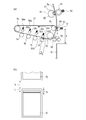
- FIG. 4A shows a schematic diagram of the intermediate transfer belt unit 10 in the second image forming mode
- FIG. 4B shows two consecutive images printed at that time.
- the second image forming mode is a mode in which image formation is performed in a state in which at least one of the plurality of photosensitive drums 1 is opposed to the primary transfer roller and the primary transfer nip portion.
- the primary transfer roller is configured to contact and be separated from the intermediate transfer belt. By separating the primary transfer roller from the intermediate transfer belt, a state where the primary transfer nip portion is not formed can be formed.
- FIG. 4A among the primary transfer rollers 50a to 50d, the primary transfer rollers 50a to 50c other than Bk located on the most downstream side in the rotation direction of the intermediate transfer belt are separated from the intermediate transfer belt 51.
- An image forming mode is shown.
- FIG. 4B illustrates the primary transfer position for the next sheet S 1 at the timing when the trailing edge of the sheet S 0 has passed through the secondary transfer nip portion in the second image forming mode of FIG. is doing.
- the monochrome mode which is the second image forming mode described in this image forming apparatus, is a state in which at least one of the plurality of photosensitive drums 1 is not opposed to the primary transfer roller and the primary transfer nip portion. This means that a monochrome image is formed. As described above, when a single color image is formed in a state where all the photosensitive drums form the primary transfer nip portion, the first image forming mode is used.
- the first image forming mode is described as a full color mode
- the second image forming mode is described as a monochrome mode.
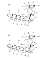
- the feature of this embodiment is that the mono color mode (between the secondary transfer nip portion 99 and the fixing nip portion immediately before the trailing edge of the sheet S 0 passes through the secondary transfer nip portion 99.
- FIG. 5A a loop larger than the full color mode (FIG. 5B) is formed.
- loop A to the virtual straight line connecting the fixing nip portion and T2 nip 99 is the deflection of the sheet S 0.
- loop amount deflection amount
- the length of the sheet S 0 between the fixing nip and T2 nip portion 99 becomes longer.
- the large loop as in the mono color mode is not formed for the following reason.
- the full color mode if a loop more than necessary is formed in accordance with the mono color mode, there is a possibility that the color shift between stations may be influenced by the pushing force to the intermediate transfer belt 51. .
- FIG. 6B shows a balance of tangential forces acting on the intermediate transfer belt 51 immediately before the trailing edge of the sheet S 0 comes out of the secondary transfer nip 99 when the loop amount is large.
- f 54 is a tangential force received from the secondary transfer counter roller 54
- f pl is a tangential force received from the sheet S 0
- f 52l is a tangential force received from the drive roller 52.
- FIG. 6C shows the moment when the trailing edge of the sheet S 0 has passed through the secondary transfer nip 99.
- the sheet S 0 and the secondary transfer roller 60 are separated from the intermediate transfer belt 51. Therefore, the tangential force received by the intermediate transfer belt 51 from the secondary transfer counter roller 54 is f 54 ′, and the tangential force received from the drive roller 52 is f 52 ′.
- the tangential force received by the intermediate transfer belt 51 from the secondary transfer counter roller 54 is the second transfer at the instant f 54 ′ when the intermediate transfer belt 51 passes through the secondary transfer nip 99 and the second transfer f 54. Since the sliding load of the bearing (not shown) of the opposing roller 54 increases, the following magnitude relationship is obtained. f 54 > f 54 '(6)
- FIG. 6D shows a case where the sheet S 0 is not in the T2 nip portion 99 and the secondary transfer roller 60 is in pressure contact with the intermediate transfer belt 51.
- the tangential force received by the intermediate transfer belt 51 from the secondary transfer roller 60 is f 60
- the tangential force received from the secondary transfer counter roller 54 is f 54 ′′
- the tangential force received from the drive roller 52 is f 52 ′′.
- Sheet S 0 is not in the secondary transfer nip portion 99, when the secondary transfer roller 60 is pressed against the intermediate transfer belt 51, wherein the tangential force acting on the intermediate transfer belt 51 balancing is as follows.
- f 54 '' + f 60 + f 0 f 52 '' ⁇ (8)
- the secondary transfer roller 60 is an intermediate transfer belt 51 Smaller when pressed against. Therefore, than the tangential force by the sheet S 0 when the sheet S 0 is in the secondary transfer nip portion 99, the smaller tangential force by the secondary transfer roller 60 when not in the secondary transfer nip 99. Therefore, the following magnitude relationship holds. f p > f 60 (9)
- the tangential force that the intermediate transfer belt 51 receives from the secondary transfer counter roller 54 is f 54 ′ when the sheet S 0 is not in the secondary transfer nip 99 and the secondary transfer roller 60 is in pressure contact with the intermediate transfer belt 51.
- f 54 ′ that passes through the secondary transfer nip 99. That is, since the secondary transfer roller 60 towards the case f 54 '' are pressed against the intermediate transfer belt 51 is larger by an amount corresponding to the sliding load increases the bearing of the secondary transferring opposed roller 54 (not shown), The following magnitude relationship holds.
- the tangential force that the intermediate transfer belt 51 receives from the secondary transfer counter roller 54 is f 54 when the sheet S 0 is in the T2 nip 99, and the secondary transfer roller 60 does not have the sheet S 0 in the secondary transfer nip 99.
- f 54 '' are pressed against the intermediate transfer belt 51 becomes following relationship. That is, when the sheet S 0 is in the secondary transfer nip 99, f 54 is increased by an increase in the sliding load of a bearing (not shown) of the secondary transfer counter roller 54, and therefore, when combined with (10).
- the following magnitude relationship holds.
- the gear which is a drive member shall deform
- ⁇ t is a time during which the trailing edge of the sheet S 0 passes through the secondary transfer nip 99 and the intermediate transfer belt 51 is not in contact with the sheet S 0 and the secondary transfer roller 60.
- FIG. 7 (b-1) When increasing the amount of loop, FIG. 7 (b-1), exits (b-2) at time t 1 shown in starting to increase the loop amount, the rear end is a secondary transfer nip portion 99 of the sheet S 0 until time t 2 to reach the loop amount required.
- the amount of deformation of the drive member of the intermediate transfer belt 51 immediately before the trailing edge of the sheet S 0 passes through the secondary transfer nip 99 is proportional to the tangential force applied to the intermediate transfer belt 51. Therefore, if the absolute deformation amount of the gear when the loop amount is large and when the loop amount is small are expressed as Z 2 and Z 1 , respectively, Z 2 > Z 1 is satisfied.
- the change in the rotational speed of the intermediate transfer belt 51 is considered as follows. Time absolute deformation amount of a driving member gear to converge again Z 0, the gear is not transmitted force from the driving unit 102 constituting the driving roller 52, the speed reduction of the intermediate transfer belt 51 by the influence It is thought to occur. Therefore, it is considered again as the absolute deformation amount is large variations lightweight gear to converge to Z 0, the time the force from the drive unit 102 which gear constituting the driving roller 52 is not transmitted becomes long.
- the relationship between the deformation amounts is ⁇ Z 2 ′ ⁇ Z 1 ′.
- the speed decrease amount is ⁇ V 1 ′
- the speed decrease amount is Becomes ⁇ V 2 ′. From the relationship ⁇ Z 2 ′ ⁇ Z 1 ′, the relationship between the speed changes is ⁇ V 2 ′ ⁇ V 1 ′.
- FIG. 8 is a schematic diagram showing the progress of the deformation of the gear that is the driving member. 8 (a-1), (a-2), and (a-3), the gear deformation process when the loop amount is small, and (b-1), (b-2), and (b-3) the loop It shows the deformation of the gear when the amount is large.
- Figure 8 shows a state before the gear trailing edge of the sheet S 0 escapes (a-1), a comparison of (b-1), towards the gear when the loop amount is large has to be deformed.
- Figure 8 speed is a degraded state of the intermediate transfer belt 51 exits the trailing edge of the sheet S 0 (a-2), the (b-2) comparing, in the case where large amount of loop shown in (b-2) Gear Is more deformed.
- FIG intermediate rotary speed of the transfer belt 51 shows how the state of the gear converges to the speed V 0 again 8 (a-3), the (b-3) comparing the deformation of the gear variants of the same degree become.
- FIG. 9 and FIG. 10 (a) show a flow chart of the loop formation sequence and a graph showing temporal changes in the fixing motor (not shown) speed, respectively.
- the loop is formed by controlling the fixing motor speed with respect to the speed of the intermediate transfer belt by the speed control circuit 101. That is, the loop can be formed by relatively controlling the rotational speeds of the intermediate transfer belt and the fixing motor by the speed control circuit 101. For example, the rotation speed of the intermediate transfer belt may be changed with respect to the rotation speed of the fixing motor.
- the speed control circuit 101 sets the fixing motor speed relative to the intermediate transfer belt speed in the mono color mode to be slower than the fixing motor speed relative to the intermediate transfer belt speed in the full color mode. Can be formed.
- a CPU of a controller unit confirms the presence or absence of a print job (step 1 (hereinafter referred to as S1)).
- the CPU detects the thickness of the sheet by the thickness detection sensor 55, the intermediate transfer belt speed (belt speed), the fixing motor speed (N 1). ) Is acquired (S2).
- the CPU confirms whether or not the state of the image forming apparatus is a mono color mode (S3).
- the mono color mode and the full color mode have different loop amount tables depending on the thickness of the sheet (e.g., evaluated by basis weight, etc.) as shown in FIG.
- the loop amount table as shown in FIG. 11 is held in, for example, a ROM included in a controller unit (not shown), and the CPU refers to the loop amount table and detects it by the thickness detection sensor 55 that is a thickness detection member. Information regarding the loop amount corresponding to the sheet thus obtained can be obtained.
- the basis weight (g / m 2 ) of the sheet is divided into predetermined regions of 105 g / m 2 or less, 105 to 120 g / m 2 , 120 to 160 g / m 2 , 160 g / m 2 or more.
- the loop amounts in the mono color mode are A 1 , A 2 , A 3 and A 4 , respectively, and the loop amounts in the full color mode are B 1 , B 2 , B 3 and B 4 , respectively.
- a 1 > B 1 , A 2 > B 2 , A 3 > B 3 , and A 4 > B 4 are satisfied.
- a sheet position detection sensor near the registration roller pair 38 detects the trailing edge of the sheet (S6), and after a predetermined time has elapsed (S7 Yes), the speed control circuit 101 sets the fixing motor speed. , switching from N 1 to N 2 (S8). That is, the control of the speed control circuit ends after the trailing edge of the transfer material has passed through the secondary transfer nip portion.
- time t 1 in FIG. 10A is the time when the trailing edge of the sheet is detected by the sheet position detection sensor near the registration roller pair 38.
- the time t 2 in FIG. 10 (a) at the time after a lapse of a predetermined time by detecting the trailing edge of the sheet by the sheet position detection sensor, a time when the fixing motor speed is switched from N 1 to N 2, This is the time at which the fixing speed control according to this embodiment is started (ON).
- the speed control circuit 101 After exit the trailing edge of the sheet secondary transfer nip (S9 Yes), the speed control circuit 101, undo the fixing motor speed, i.e., returning from N 2 to N 1 (S10).
- the time t 3 in FIG. 10 (a) is the time when the sheet rear end leaves the T2 nip
- the time t 4 is the time after time t 3.
- V f1 is a value substantially equal to the transfer speed V b of the transfer material in the secondary transfer nip portion, and satisfies V f1 > V f2 .
- the time required to form a predetermined loop amount can be changed by changing two parameters t 2 and V f2 .
- a loop is formed over time (t 2 is decreased and V f2 is increased).
- the change rate of the pushing force against the intermediate transfer belt 51 due to the loop formation can be reduced, and the load fluctuation applied to the intermediate transfer belt 51 can be reduced.
- t 2 can be changed within the range of t 1 ⁇ t 2 ⁇ t 3 .
- V f2 can also be changed within the allowable torque range of the fixing motor.
- the intermediate transfer that occurs when the transfer material is removed from the secondary transfer nip portion is reduced. It is possible to obtain high-quality images by suppressing belt speed fluctuations.
- Example 1 the sheet loop amount when passing through the T2 nip portion in the mono color mode was controlled to be larger than the loop amount in the full color mode. Even in the same mode, when the sheet is thin, the loop amount is controlled to be larger than when the sheet is thick.
- the second embodiment in addition to the first embodiment, a method corresponding to a temperature change in the diameter of the heating rotator 16 and the pressure roller 15 will be described.
- the transfer speed of the transfer material in the fixing nip portion varies when it is affected by expansion and contraction due to temperature changes in the diameters of the heating rotator 16 and the pressure roller 15, and as a result, between the T2 nip portion and the fixing nip portion. There may be variations in the amount of loop formed.
- the design is such that when the sheet trailing edge passes through the T2 nip portion, the loop amount is greater than or equal to a predetermined amount under conditions where the conveyance speed at the fixing nip is the fastest (conditions where the loop tends to be the smallest). There is no problem to do. However, there may be restrictions such as the space of the paper conveyance path from the secondary transfer nip portion to the fixing nip portion. If the variation in the loop amount due to temperature changes in the diameters of the heating rotator 16 and the pressure roller 15 cannot be allowed due to such a restriction, the loop is formed by changing to the optimum fixing motor speed according to the temperature. It is necessary to stabilize the amount.
- a configuration in which a non-contact sensor 95 (loop amount detection member) for measuring the sheet position is considered.
- the CPU of the controller unit adjusts the fixing motor speed so that the loop amount becomes constant (predetermined loop amount) based on the measurement result (detection result). Change.
- a configuration in which a temperature detection sensor (not shown) that is a temperature detection member is attached to the pressure roller 15 is conceivable.
- the temperature detection sensor detects the temperature of the pressure roller 15, and based on the detection result of the temperature detection member, the speed control circuit controls the fixing motor to keep the loop amount constant. It can also be considered.
- a thermistor 91 that monitors the temperature of the heater 90 of the heating rotator 16 is used as a temperature detection member.
- the CPU of the controller unit (not shown) cuts the heater 90 at a predetermined timing, monitors the rate of decrease of the heater 90 per unit time by the thermistor 91, and estimates the temperature of the pressure roller 15 so that the fixing nip unit Determine the transport speed.
- a method in which the speed control circuit changes the fixing motor speed according to the determined transport speed can be considered. This makes the amount of loop formed constant.
Landscapes
- Physics & Mathematics (AREA)
- General Physics & Mathematics (AREA)
- Electrostatic Charge, Transfer And Separation In Electrography (AREA)
- Control Or Security For Electrophotography (AREA)
- Fixing For Electrophotography (AREA)
Abstract
転写材が二次転写部材と中間転写体で形成される二次転写ニップ部から抜けた際に生じる中間転写体の速度変動による画像不良を課題とする。 一次転写ローラ50a~50cが中間転写ベルト51から離間して画像形成を行うモノカラーモードが実行される場合における二次転写ニップ部と定着ニップ部の間の転写材のループ量が、感光ドラム1a~1dによって画像形成を行うフルカラーモードが実行される場合における二次転写ニップ部と定着ニップ部の間の転写材のループ量よりも大きくなるように、二次転写ニップ部と定着ニップ部の間の転写材にループを形成する。
Description
本発明は、電子写真方式によって転写材上に画像を形成する画像形成装置に関するものである。
近年、レーザプリンタや複写機などの画像形成装置は、高速・高画質化が求められている。そのために、画像形成装置では、感光ドラム等の像担持体に形成されたトナー像をベルトなどの中間転写体に転写し、その後、トナー像を中間転写体からシートなどの転写材に転写する構成が多く採用されている。
カラー画像を高速、且つ、高画質に形成することの可能な画像形成装置として、タンデム方式のフルカラー機が普及している。例えば、イエロー(Y)、マゼンタ(M)、シアン(C)、ブラック(Bk)の4つの画像形成部が並列に配置され、画像形成部の感光ドラムが中間転写体である中間転写ベルトに接触している構成である。ここでは、一次転写部材を使って、中間転写ベルトを感光ドラムに押圧し、接触させる。
上記のような各画像形成部によって、中間転写ベルト上にトナー像を重畳させた後に、中間転写ベルトから転写材上に二次転写し、定着によってトナー像を定着させることで、フルカラー画像を形成する。
ところで、フルカラーの画像を形成可能な画像形成装置では、全ての感光ドラムを中間転写ベルトに接触させた状態で、全ての色の画像形成部を機能させるフルカラーモードを有する。さらに、少なくとも一つの感光ドラムと中間転写ベルトを離間させた状態で、少なくとも一つ(例えば黒)の画像形成部を機能させるモノカラーモードの2つを持っている場合がある。
このような2つのモードを備える目的は、主に、画像形成部の感光ドラムの寿命を延ばすことと、トナーの消費量を減らすことである。例えば黒のみを使用するモノカラーモードでは、機能させない画像形成部の感光ドラムと中間転写ベルトを離間によって接触させないことで、感光ドラム表面の摩耗を防ぎ、感光ドラムの寿命を延ばすことが可能である。また、感光ドラムのクリーニングでブレードを使用しているものでは、感光ドラムが回転を停止しているので、ブレードのめくれ防止のための潤滑の役割としてのトナーを使用する必要がなく、トナーの消費量を減らすことが可能である。
しかしながら、モノカラーモードは、フルカラーモードと比較して、中間転写ベルトに接触している感光ドラムの数が少ない。即ち、感光ドラムと一次転写部材で中間転写ベルトを挟持する拘束点が少なく、中間転写ベルトに対する挟持力が小さくなる。このようにベルトの狭持力が小さくなるモノカラーモードでは、中間転写ベルトと二次転写部材で形成される二次転写ニップ部に、転写材であるシートの先端が突入、又は、後端が抜けるときに、中間転写ベルトに対する負荷が変動する。このようにして生じた負荷変動が、中間転写ベルトを駆動する駆動部材に影響を与え、中間転写ベルトの速度を変動させてしまう可能性がある。その結果、中間転写ベルトに速度変動が発生した影響で、一次転写ニップ部で転写中のトナー像に、濃度差が生じる課題が生じる。
特許文献1では、フルカラーモードとモノカラーモードで、モノカラーモードで中間転写ベルトに接触する一次転写部材の中間転写ベルトに対する押圧力を、フルカラーモードの時の押圧力よりも大きくする構成が提案されている。
しかしながら、特許文献1記載の提案では、中間転写ベルトの拘束点の数は変わらないので、十分なレベルまで拘束力を上げるには、相当な一次転写部材による押圧力が必要になる。押圧力を上げすぎると、一次転写部材と中間転写ベルトのニップ幅が大きくなりすぎて、画像不良が発生する可能性がある。
本発明は以上の点に着目してなされたもので、転写材が二次転写部材と中間転写ベルトで形成される二次転写ニップ部から抜けた際に生じる中間転写ベルトの速度変動を抑制し、高画質の画像を得ることができる画像形成装置を提供することを目的とする。
上述の課題を解決するために、本発明は、回転可能な中間転写ベルトと、前記中間転写ベルトの回転方向に配列されトナー像を担持する複数の像担持体と、前記複数の像担持体に対して前記中間転写ベルトを介して対向しており、夫々が対向する前記像担持体と1次転写ニップ部を形成可能な複数の一次転写部材と、前記一次転写部材によって前記中間転写ベルトに転写されたトナー像を二次転写ニップ部で転写材に転写する二次転写部材と、前記二次転写部材によって転写されたトナー像を定着ニップ部で転写材に定着する定着部と、前記二次転写ニップ部における転写材の搬送速度と前記定着ニップ部における転写材の搬送速度を制御する速度制御回路と、を有し、前記複数の像担持体夫々が対向する前記一次転写部材と前記一次転写ニップ部を形成している状態で画像形成を行なう第一の画像形成モードと、前記複数の像担持体のうちの少なくとも一つが対向する前記一次転写部材と前記一次転写ニップ部を形成していない状態で画像形成を行なう第二の画像形成モードと、を実行可能な画像形成装置において、前記速度制御回路は、前記第二の画像形成モードが実行される場合における前記二次転写ニップ部と前記定着ニップ部の間の転写材のループ量が、前記第一の画像形成モードが実行される場合における前記二次転写ニップ部と前記定着ニップ部の間の転写材のループ量よりも大きくなるように、前記第二の画像形成モードが実行される場合に前記二次転写ニップ部における転写材の搬送速度と前記定着ニップ部における転写材の搬送速度を制御することを特徴とする。
本発明によれば、転写材が二次転写部材と中間転写ベルトで形成される二次転写ニップ部から抜けた際に生じる中間転写ベルトの速度変動を抑制する効果がある。
以下に、本発明に係る画像形成装置の実施形態について図面により詳しく説明する。
画像形成装置の全体構成について、図1を参照して概要説明する。なお、本発明に係る画像形成装置は、画像形成装置本体であるカラーレーザプリンタ(以下、プリンタ部)100の構成であり、図1はその全体構成を示す縦断面図である。
図1に示すプリンタ部100は、装置本体に対して着脱自在なプロセスカートリッジ3a,3b,3c,3dを備えている。これら4個のプロセスカートリッジ3a,3b,3c,3dは、同一構造であるが、異なる色、すなわち、イエロー(Y),マゼンタ(M),シアン(C),ブラック(Bk)のトナーによる画像を形成する点で相違している。プロセスカートリッジ3a,3b,3c,3dは、現像ユニット4a,4b,4c,4dと、クリーナユニット5a,5b,5c,5dを有している。
現像ユニット4a,4b,4c,4dは、現像ローラ6a,6b,6c,6dと、現像剤塗布ローラ7a,7b,7c,7d、及びトナー容器を有している。一方、クリーナユニット5a,5b,5c,5dは、像担持体である感光ドラム1a,1b,1c,1dと、帯電ローラ2a,2b,2c,2dと、ドラムクリーニングブレード8a,8b,8c,8dと、廃トナー容器と、を有している。
プロセスカートリッジ3a,3b,3c,3dの鉛直下方にはスキャナユニット9が配置され、感光ドラム1a,1b,1c,1dに対して画像信号に基づいて露光する。感光ドラム1a,1b,1c,1dは、帯電ローラ2a,2b,2c,2dによって所定の負極性の電位に帯電された後、スキャナユニット9によってそれぞれ静電潜像が形成される。この静電潜像は現像ユニット4a,4b,4c,4dによって負極性のトナーが付着され、それぞれY、M、C、Bkのトナー像が現像される。
中間転写ベルトユニット10は、駆動ローラ52、テンションローラ53、二次転写対向ローラ54、一次転写ローラ50a~50d、中間転写ベルト51から構成される。一次転写ローラ50a~50dは一次転写部材である。中間転写体である無端状の中間転写ベルト51は、張架ローラである駆動ローラ52、テンションローラ53、二次転写対向ローラ54に張架されている。中間転写ベルトは、駆動ローラ52が回転することで回転可能である。さらに、テンションローラ53が中間転写ベルト51の内側から外側に向かって、(矢印T方向に)張力をかけている。また、各感光ドラム1a,1b,1c,1dに対向して、中間転写ベルト51の内面側に一次転写部材である一次転写ローラ50a,50b,50c,50dが設置されている。一次転写ローラ50a,50b,50c,50dには、不図示のバイアス印加手段により転写電圧が印加される構成となっている。各一次転写ローラは、中間転写ベルトを介して対向する各感光ドラムと1次転写ニップ部を形成可能である。像担持体である感光ドラム1a,1b,1c,1dは、中間転写ベルト51の回転方向に沿って、配列されている。
感光ドラム1a~1dは、図1における時計周りに回転し、中間転写ベルト51を反時計周りに回転させる。感光ドラム1a,1b,1c,1d上に形成されたトナー像は、さらに一次転写ローラ50a,50b,50c,50dに正極性の転写電圧を印加することにより、感光ドラム1a上のトナー像から順次、中間転写ベルト51上に一次転写される。そして、中間転写ベルト51上に4色のトナー像が重なった状態で二次転写ニップ部13まで搬送される。
一方、トナー像転写後に、感光ドラム1a,1b,1c,1d表面に残ったトナーは、ドラムクリーニングブレード8a,8b,8c,8dによって除去される。また、転写材であるシートSへの二次転写後に中間転写ベルト51上に残ったトナーは、転写ベルトクリーニング装置11によって除去される。そして、除去されたトナーは、廃トナー搬送路(不図示)を通過し、装置奥面部に配置された廃トナー回収容器(不図示)へと回収される。
本実施例の画像形成装置では、2つのシート給紙装置(シート給紙部)を有する。第1のシート給紙部はプリンタ部100内部に設けられた本体シート給紙部20、第2のシート給紙部はプリンタ部100側面に設けられた手差しシート給紙部30である。
本体シート給紙部20は、給紙カセット21が画像形成装置本体の位置決め部に対して、突き当てるように挿入される。本実施例では、図1の手前に設置されている前側板(不図示)に対して突き当てている。給紙カセット21での、搬送方向に対して直角な方向(シートの幅方向)のシートの位置決めは、シートの大きさに合わせて給紙カセット21に移動可能に取り付けられている図上手前側のサイド規制板19a及び図上奥側のサイド規制板19bによって行われる。これらによって、シートSはその上面側だけを開放した状態にて位置決めされた状態で積載され、画像形成装置本体に対して、高精度に位置決めされている。
シート給紙部20はまた、シートSを収納する給紙カセット21内からシートSを給紙する給紙ローラ22と、分離手段である分離ローラ23を有する。給紙カセット21に収納されたシートSは、給紙ローラ22に圧接され、分離ローラ23によって一枚ずつ分離され搬送される。そして、分離されたシートSは、本体給紙搬送路25を経てレジストローラ対38に搬送される。
手差しシート給紙部30は、シートSを積載する中板31と、中板31の最上のシートSを給紙する給紙ローラ32と、分離手段である分離パット33を有する。さらに手差しシート給紙部30は、搬送方向に対して直角な方向(シートの幅方向)の位置を規制する図上手前側のサイド規制板37a及び図上奥側のサイド規制板37bを有する。中板31が持ち上がり、中板31上に積載されたシートSが給紙ローラ32に圧接され、分離パット33によって一枚ずつ分離され搬送される。そして、分離されたシートSは手差し給紙搬送路34を経て、再給紙ローラ対35に搬送され、再給紙搬送路36を通過してレジストローラ対38に搬送される。
以上、説明したように、プリンタ部100のレジストローラ対38上流側では、2つの搬送路が合流する構成である。
レジストローラ対38によりシートSは二次転写ニップ部13に搬送される。二次転写ニップ部13は、二次転写部材である二次転写ローラ60と中間転写ベルト51によって形成される。二次転写ニップ部13において、二次転写部材である二次転写ローラ60に正極性の転写電圧を印加することにより、搬送されたシートSに、中間転写ベルト51上の4色のトナー像を二次転写する。
定着部は、加熱回転体16と、加圧部材15を有する。15は加圧部材としての弾性加圧ローラ(以下、加圧ローラ)であり、この加熱回転体16と加圧ローラ15との圧接により定着ニップ部が形成されている。
加熱回転体16は、ヒータ90とサーミスタ91を内蔵しており、ヒータ90の温度をサーミスタ91によってモニタしながら、所定の温度に加熱している(図2参照)。未定着トナー像を担持したシートSが、定着ニップ部に搬送され、定着ニップ部にて挟持搬送されることで、未定着トナー像が加熱されて熱定着される。定着ニップ部を通過したシートSは排紙ユニットに設置された排紙ローラ17によって排出トレイ18に排出される。
本実施例の画像形成装置は、第一の画像形成モードと第二の画像形成モードの二つのモードを少なくとも実行可能である。
次に、第一の画像形成モードであり、4色全ての感光ドラムに画像が形成されるフルカラーモードの概略図を図2(a)に、その際にプリントされる連続2枚の画像を図2(b)に示す。ここで、第一の画像形成モードとは、複数の感光ドラム1a~1d夫々が、対向する一次転写ローラ50a~50dと1次転写ニップ部を形成している状態で画像形成を行うモードである。よって、全ての感光ドラムが一次転写ニップ部を形成していればフルカラーの画像を形成しなくてもよい。例えば、全ての感光ドラムが一次転写ニップ部を形成している状態で、1色のみの画像を形成するモードも、第一の画像形成モードに含まれる。
一次転写ローラ50a~50dは、中間転写ベルト51に対して当接離間可能である。さらに、一次転写ローラ50a~50dは、中間転写ベルト51に対して当接した際に、それぞれ圧縮バネ56a~56dで中間転写ベルト51に向かって押圧されている。一次転写ニップ部は、圧縮バネ56によって押圧されている一次転写ローラと、対向する感光ドラムとが、中間転写ベルトを介して形成している。
二次転写ローラ60は、中間転写ベルトに対して当接離間可能である。二次転写ローラ60は、圧縮バネ61によって中間転写ベルト51と二次転写対向ローラ54に所定の接触圧で圧接され、二次転写ニップ部99を形成している。図1で示した本体シート給紙部20又は手差しシート給紙部30で給紙されたシートSは、レジストローラ対38で一時停止する。その際に、厚み検知部材である厚さ検知センサ55によって、シートSの厚さを検知する。その後、感光ドラム1a~1d上に形成されたトナー像は、それぞれ、一次転写ニップ部80a~80dにおいて、順次、中間転写ベルト51上に重ねて転写される。その後、二次転写ニップ部において、中間転写ベルト51上のトナー像にタイミングを合わせて搬送さるシートSに転写される。シートSに転写された未定着トナー像は、加熱回転体16と加圧ローラ15で形成される定着ニップ部で熱定着される。なお、92は定着加圧バネであり、加圧ローラ15は定着加圧バネ92によって加熱回転体16に圧接され、定着ニップ部を形成する。
各ローラの駆動、定着温度等の制御は、例えばCPUやRAM、ROMを有する速度制御回路101により行われる。さらに、図3(a)で示すように、速度制御回路101は、中間転写ベルト51を駆動させる駆動ローラ52の回転速度と、定着部15の加圧ローラ15の回転速度を制御することが可能である。速度制御回路101は、複数でもよく、二次転写ニップ部における転写材の搬送速度と、定着ニップ部における転写材の搬送速度を制御することができる構成であればよい。
図2(a)のシートS0が二次転写ニップ部を抜けた際に生じる中間転写ベルト51の負荷変動について説明する。図3(b)に、駆動ローラ52を駆動するベルト駆動部102の概略図を示す。シートS0が二次転写ニップ部を抜けると、ベルト駆動部102を構成するギアに負荷が発生し、中間転写ベルト51に速度変動が発生する。それによって、シートS0の次に給紙されるシートS1に転写するためのトナー像が一次転写部ニップ部で乱れる現象が発生する。この現象が、シートS0の後端が二次転写ニップ部を抜けた際に次のシートS1に対して発生する「シート後端抜けブレ」と呼ばれる画像不良である。
この現象は、図1で示すように、一次転写ニップ部と二次転写ニップ部の間に、駆動ローラ52が配置されており、一次転写ニップ部を形成する領域にある中間転写ベルト51が駆動ローラによって引っ張られる構成の時に、より発生し易い課題である。
図2(b)は、シートS0の後端が二次転写ニップ部を抜けたタイミングにおける、次のシートS1に対する一次転写の位置を説明する概略図である。連続プリントの二枚目以降、且つ、ベルト回転方向最下流の一次転写ニップ部80dから二次転写ニップ部99までの距離をY(図2(a)中破線矢印)、シートS0とシートS1の紙間をXとする。さらに、シートS1の先端余白をLとすると、Y+l3>X+Lを満たした場合は、先のシートSoが二次転写ニップ部を抜けた時の影響を、次のシートS1が受けない。しかしながら、その条件を満たすにはXを大きくする、即ち、シートとシートの搬送間隔を大きくする必要が生じる。シートとシートの搬送間隔を大きくしてしまうと、大幅にスループットを低下させてしまう。
「シート後端抜けブレ」と呼ばれる画像不良は、第2の画像形成モードを実行する時により発生し易い。第2の画像形成モードは、第1の画像形成モードの場合に比べて、一次転写部材と感光ドラムで中間転写ベルト51を挟持する拘束点の数が少ないため、先のシートSoが二次転写ニップ部を抜けた時の影響を強く受け易い。第2の画像形成モード時の中間転写ベルトユニット10の概略図を図4(a)に、その際にプリントされる連続2枚の画像を図4(b)に示す。
ここで、第2の画像形成モードとは、複数の感光ドラム1のうちの少なくとも一つが対向する一次転写ローラと1次転写ニップ部を形成していない状態で画像形成を行なうモードである。一次転写ローラは、中間転写ベルトに対して当接離間可能な構成である。一次転写ローラを中間転写ベルトに対して離間させることで、1次転写ニップ部を形成していない状態を形成可能である。図4(a)では、一次転写ローラ50a~50dのうちの中間転写ベルトの回転方向における最下流に位置するBk以外の一次転写ローラ50a~50cが中間転写ベルト51から離間している第2の画像形成モードを示している。図4(b)では、図4(a)の第2の画像形成モードにおける、シートS0の後端が二次転写ニップ部を抜けたタイミングにおける次のシートS1に対する一次転写の位置を説明している。
尚、本画像形成装置で説明する第2の画像形成モードであるモノクロモードとは、複数の感光ドラム1のうちの少なくとも一つが対向する一次転写ローラと1次転写ニップ部を形成していない状態で単色の画像を形成することを意味している。上述したように、全ての感光ドラムが一次転写ニップ部を形成している状態で単色画像を形成する場合は第1の画像形成モードである。
以下の説明では、第一の画像形成モードをフルカラーモード、第二の画像形成モードをモノクロモード、として説明する。
本実施例の特徴は、図5に示すように、シートS0の後端が二次転写ニップ部99を抜ける直前に、二次転写ニップ部99と定着ニップ部の間で、モノカラーモード(図5(a))においてフルカラーモード(図5(b))よりも大きいループを形成することである。
二次転写ニップ部99と定着ニップ部の間で大きなループを形成し、中間転写ベルト51に対して転写材からより大きな押し込み力を発生させることで、中間転写ベルト51の狭持力の弱さによる画像不良を抑制する。ここで、ループとは、T2ニップ部99と定着ニップ部を結んだ仮想の直線に対する、シートS0の撓みである。ループ量(撓み量)が大きいほど、二次転写ニップ部99と定着ニップ部の直線距離に対する、T2ニップ部99と定着ニップ部の間のシートS0の長さが長くなる。
ここで、フルカラーモードにおいて、モノカラーモードのような大きなループを形成しないのは次の理由による。すなわち、フルカラーモードにおいて、モノカラーモードに合わせて、必要以上のループを形成してしまうと、中間転写ベルト51への押し込み力によって、ステーション間の色ずれに影響を与える可能性があるからである。
よって、モノカラーモード、及び、フルカラーモードにおいて、それぞれの中間転写ベルト51の狭持力に応じた必要最小限のループを形成することが重要であり、本実施例は、それを可能にする。
図6(a)は、ループ量が小さい場合における、シートS0の後端が二次転写ニップ部99から抜ける直前の中間転写ベルト51に働く接線力のつり合いを表している。f54は、二次転写ニップ部99にシートS0がある場合に、二次転写対向ローラ54から受ける接線力、fpは、シートS0から受ける接線力、f52は駆動ローラ52から受ける接線力である。また、f0はその他(ブレードや一次転写ローラ(不図示))などから受ける接線力である。
ループ量が小さい場合における、シートS0の後端が二次転写ニップ部99から抜ける直前の中間転写ベルト51に働く接線力の釣り合いの式は以下のようになる。
f54+fp+f0=f52・・・(1)
f54+fp+f0=f52・・・(1)
図6(b)は、ループ量が大きい場合における、シートS0の後端が二次転写ニップ部99から抜ける直前の中間転写ベルト51に働く接線力のつり合いを表している。f54は、二次転写対向ローラ54から受ける接線力、fplは、シートS0から受ける接線力、f52lは駆動ローラ52から受ける接線力である。ループ量が大きい場合における、シートS0の後端が二次転写ニップ部99から抜ける直前の中間転写ベルト51に働く接線力の釣り合いの式は以下のようになる。
f54+fpl+f0=f52l・・・(2)
f54+fpl+f0=f52l・・・(2)
シートS0のループが大きいほど、シートS0による中間転写ベルト51への押し込み力が大きいので、以下の大小関係が成り立つ。
fpl>fp・・・(3)
fpl>fp・・・(3)
(1)、(2)、(3)より、駆動ローラ52から中間転写ベルト51が受ける接線力に関して、以下の大小関係が成り立つ。
f52l>f52・・・(4)
f52l>f52・・・(4)
ただし、同じループ量でも、シートS0の厚みが薄い程、転写材による中間転写ベルト51に対する押し込み力が小さくなる。よって、シート後端ブレを改善するために必要な押し込み力を得るためには、シートS0の厚みが薄い程、ループ量を増やす必要がある。
次に、図6(c)は、シートS0の後端が二次転写ニップ部99を抜けた瞬間を表している。この瞬間は、シートS0、及び、二次転写ローラ60は、中間転写ベルト51に対して離間している状態である。そこで、中間転写ベルト51が、二次転写対向ローラ54から受ける接線力をf54’、駆動ローラ52から受ける接線力をf52’とする。シートS0の後端が二次転写ニップ部99を抜けた瞬間の中間転写ベルト51に働く接線力の釣り合いの式は以下のようになる。
f54’+f0=f52’・・・(5)
f54’+f0=f52’・・・(5)
中間転写ベルト51が二次転写対向ローラ54から受ける接線力は、二次転写ニップ部99を抜けた瞬間f54’と二次転写時f54では、二次転写時の方が、二次転写対向ローラ54の軸受け(不図示)の摺動負荷が増えるため、以下の大小関係となる。
f54>f54’・・・(6)
f54>f54’・・・(6)
(1)、(5)、(6)から、中間点転写ベルト51が、駆動ローラ52から受ける接線力に関して、以下の大小関係が成り立つ。
f52l>f52>f52’・・・(7)
f52l>f52>f52’・・・(7)
次に、図6(d)は、シートS0がT2ニップ部99になく、二次転写ローラ60が中間転写ベルト51に圧接している場合を表している。ここで、中間転写ベルト51が、二次転写ローラ60から受ける接線力をf60、二次転写対向ローラ54から受ける接線力をf54’’、駆動ローラ52から受ける接線力をf52’’とする。シートS0が二次転写ニップ部99になく、二次転写ローラ60が中間転写ベルト51に圧接している場合に、中間転写ベルト51に働く接線力の釣り合いの式は以下のようになる。
f54’’+f60+f0=f52’’・・・(8)
f54’’+f60+f0=f52’’・・・(8)
ここで、圧縮バネ61の付勢力は、二次転写ニップ部99にシートS0がある場合よりも、シートS0が二次転写ニップ部99になく、二次転写ローラ60が中間転写ベルト51に圧接している場合の方が小さい。このため、シートS0が二次転写ニップ部99にある場合のシートS0による接線力よりも、二次転写ニップ部99にない場合の二次転写ローラ60による接線力の方が小さい。よって、次の大小関係が成り立つ。
fp>f60・・・(9)
fp>f60・・・(9)
また、中間転写ベルト51が二次転写対向ローラ54から受ける接線力は、シートS0が二次転写ニップ部99になく二次転写ローラ60が中間転写ベルト51に圧接している場合f54’’と二次転写ニップ部99を抜けた瞬間f54’では次のような関係となる。すなわち、二次転写ローラ60が中間転写ベルト51に圧接している場合f54’’の方が、二次転写対向ローラ54の軸受け(不図示)の摺動負荷が増える分だけ大きくなるため、以下の大小関係が成り立つ。
f54’’>f54’・・・(10)
f54’’>f54’・・・(10)
中間転写ベルト51が二次転写対向ローラ54から受ける接線力は、シートS0がT2ニップ部99にある場合f54と、シートS0が二次転写ニップ部99になく二次転写ローラ60が中間転写ベルト51に圧接している場合f54’’では次のような関係となる。すなわち、シートS0が二次転写ニップ部99にある場合f54の方が二次転写対向ローラ54の軸受け(不図示)の摺動負荷が増える分だけ大きくなるため、(10)と合わせると、以下の大小関係が成り立つ。
f54>f54’’>f54’・・・(11)
f54>f54’’>f54’・・・(11)
(5)、(8)、(11)から、中間点転写ベルト51が駆動ローラ52よって受ける接線力に関して、以下の大小関係が成り立つ。
f52’’>f52’・・・(12)
f52’’>f52’・・・(12)
(1)、(8)、(9)、(11)と(12)を合わせると、駆動ローラ52による接線力に関して、以下の大小関係が成り立つ。
f52l>f52>f52’’>f52’・・・(13)
f52l>f52>f52’’>f52’・・・(13)
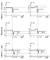
図7に、シートS0の後端が抜ける直前から直後までの中間転写ベルト51に働く接線力の時間変化について、それぞれ、ループ量が小さい場合(a-1)、ループ量が大きい場合(b-1)について示す。また、中間転写ベルト51の駆動部材(不図示)の変形量の時間変化を、それぞれ、ループ量が小さい場合(a-2)、ループ量が大きい場合(b-2)について示す。また、中間転写ベルト51の速度の時間変化を、それぞれ、ループ量が小さい場合(a-3)、ループ量が大きい場合(b-3)について示す。
ここでは、式(13)にある駆動ローラ52による中間転写ベルト51に働く接線力が大きい程、駆動ローラ52の駆動負荷が大きく、駆動部102を構成する各駆動部材であるギアの変形量は接線力に比例すると考える。尚、駆動部材であるギアは弾性限度を超えない範囲で変形するものとする。また、Δtは、シートS0の後端が二次転写ニップ部99を抜けて、中間転写ベルト51がシートS0、及び、二次転写ローラ60に触れていない時間とする。
ループ量を大きくする場合には、図7(b-1)、(b-2)に示す時刻t1でループ量を大きくし始めて、シートS0の後端が二次転写ニップ部99を抜ける時刻t2までに必要なループ量に達するようにする。
前述したように、シートS0の後端が二次転写ニップ部99を抜ける時刻t2の直前では、中間転写ベルト51に働く接線力は、ループ量を大きくした場合の方が、ループ量が小さいよりも転写材による押し込み力の差分だけ大きい(f52l>f52)。しかし、シートS0の後端が二次転写ニップ部99を抜けた時刻t2からΔtの間は、瞬間的に同じ接線力f52’に下がる。一方、シートS0の後端が二次転写ニップ部99を抜ける直前の中間転写ベルト51の駆動部材の変形量は、中間転写ベルト51にかかる接線力に比例する。よって、ループ量が大きい場合と、ループ量が小さい場合のギアの絶対変形量を、それぞれ、Z2、Z1と表すと、Z2>Z1となる。
図7(a-1)、(b-1)に示すように、シートSの後端が二次転写ニップ部99を抜け、時間Δt経過するまでは、中間転写ベルトにかかる接線力(f52’)は急激に減少する。中間転写ベルトにかかる接線力が減少すると、ギアに対する負荷が減るためギアの絶対変形量は減少していく。
接線力が再び増加し始める時刻t2+Δtにおいて、ループ量が大きい場合のギアの絶対変形量をZ2’、ループ量が小さい場合のギアの絶対変形量をZ1’とする。そうすると、t2からt2+Δtまでのギアの変形量の減少量はほぼ等しいと考えられるため、Z1-Z1’=Z2-Z2’が成り立つ。以上から、Z2’>Z1’となる。
その後は、図7(a-2)、(b-2)に示すように、ギアの絶対変形量は、両方ともZ0に収束する。図7(a-3)、(b-3)に示すように、ループ量が大きい場合も、ループ量が小さい場合も、中間転写ベルト51の回転速度は、シートS0の後端が二次転写ニップ部99を抜けるまでは、速度V0に収束している。シートSの後端が二次転写ニップ部99を抜けると、中間転写ベルト51には、速度変化が生じる。速度変化の発生した後に、中間転写ベルト51の回転速度は、再び速度V0に収束する。
以上から、中間転写ベルト51の回転速度の変化は、以下のように考えられる。駆動部材であるギアの絶対変形量が再びZ0に収束するまでの時間は、ギアが構成する駆動部102から駆動ローラ52に力が伝達されなくなり、その影響で中間転写ベルト51の速度低下が発生すると考えられる。よって、再び絶対変形量がZ0に収束するまでのギアの変軽量が大きいほど、ギアが構成する駆動部102から駆動ローラ52に力が伝達されない時間が長くなると考えられる。
ループ量が大きい場合と、ループ量が小さい場合で、シートS0の後端が二次転写ニップ部99を抜けて、駆動部材の変形量が最も減少したところから、再び増加するまでの駆動部材の変形量を、ぞれぞれ、ΔZ2’、ΔZ1’とする。
そうすると変形量の関係は、ΔZ2’<ΔZ1’となる。図7(a-3)、(b-3)に示すように、変形量がΔZ1’の場合は、速度低下量はΔV1’となり、変形量がΔZ2’の場合は、速度低下量はΔV2’となる。ΔZ2’<ΔZ1’という関係から、速度変化量の関係は、ΔV2’<ΔV1’となる。
よって、ループ量を大きくする場合の方が、駆動部材の変形量が小さく、したがって中間転写ベルト51の速度低下は小さいということになる。図8は、駆動部材であるギアの変形の経過を表す概略図である。図8(a-1)、(a-2)、(a-3)にループ量が小さい場合のギアの変形経過、(b-1)、(b-2)、(b-3)にループ量が大きい場合のギアの変形経過を示している。シートS0の後端が抜ける前のギアの様子を示している図8(a-1)、(b-1)を比較すると、ループ量が大きい場合のギアのほうが、より変形している。シートS0の後端が抜け中間転写ベルト51の速度が低下した状態の図8(a-2)、(b-2)を比較すると、(b-2)で示すループ量が大きい場合のギアのほうが、より変形している。中間転写ベルト51の回転速度が、再び速度V0に収束した状態のギアの様子を示している図8(a-3)、(b-3)を比較すると、ギアの変形は同じ程度の変形になる。
以上から、シートS0の後端が二次転写ニップ部を抜ける直前にループ量を大きくして、中間転写ベルト51に対して、押し込み力を発生させた状態で抜けるようにすることで、負荷変動による中間転写ベルト51の速度低下を緩和することができる。そして、画像不良の発生を抑制することが可能になる。
尚、ギアの材質を金属製のものにしてギアの変形を抑える方法では、ギアの剛性を上げていくと発生する走査線間隔のずれ等の画像不良が生じ易い。樹脂製で高剛性でないギアを駆動部材によって、走査線間隔のずれ等の画像不良を抑制することが可能である。
次に、二次転写ニップ部から定着ニップの間で転写材にループを形成するシーケンスについて説明する。ループ形成シーケンスのフローチャートと、定着モータ(不図示)速度の時間変化を表したグラフをそれぞれ、図9、図10(a)に示す。本実施例では、ループの形成を、速度制御回路101によって、中間転写ベルトの速度に対する定着モータ速度を制御することにより行う。即ち、ループの形成は、速度制御回路101によって、中間転写ベルトと定着モータの回転速度を相対的に制御することで可能である。例えば、中間転写ベルトの回転速度を、定着モータの回転速度に対して変更させる構成であっても良い。形成されるループ量は、中間転写ベルトの速度に対する定着モータ速度を遅くすると、例えば中間転写ベルトの速度に対する定着モータ速度が同等の場合よりも大きくなる。本実施例では、速度制御回路101によって、モノカラーモードにおける中間転写ベルトの速度に対する定着モータ速度は、フルカラーモードにおける中間転写ベルトの速度に対する定着モータ速度よりも遅く設定されているため、大きなループ量を形成できる。
まず、不図示のコントローラ部のCPUがプリントジョブの有無を確認(ステップ1(以下S1のように記す))する。ここで、CPUはプリントジョブが「有り」の場合には(S1 Yes)、シートの厚さを厚さ検知センサ55により検知して、中間転写ベルト速度(ベルト速度)、定着モータ速度(N1)の情報を取得する(S2)。次に、CPUは画像形成装置の状態がモノカラーモードであるかどうかを確認する(S3)。
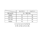
ここで、モノカラーモード、及び、フルカラーモードは、図11に示すような、シートの厚み(例えば坪量等で評価する)によって、別々のループ量テーブルを持っている。なお、図11に示すようなループ量テーブルは、例えば不図示のコントローラ部が有するROMに保持されており、CPUはループ量テーブルを参照し、厚さ検知部材である厚さ検知センサ55により検知したシートに対応するループ量に関する情報を得ることができる。
まず、シートの坪量(g/m2)を105g/m2以下、105~120g/m2、120~160g/m2、160g/m2以上の所定の領域に分ける。モノカラーモードの場合のループ量は、それぞれ、A1、A2、A3、A4、フルカラーモードの場合のループ量は、それぞれ、B1、B2、B3、B4とする。前述したように、モノカラーモードでは、フルカラーモードよりも大きいループが必要なため、A1>B1、A2>B2、A3>B3、A4>B4を満たす。また、シートの厚み(坪量)が薄い程転写材の剛性が弱いため、必要な押し込み力を得るには、より大きいループが必要になる。よって、A1>A2>A3>A4、B1>B2>B3>B4の関係である。
前述したループ量テーブルから、モノカラーモードの場合は(S3 Yes)ループ量Aを選択し(S4a)、フルカラーモードの場合は(S3 No)ループ量Bを選択する(S4b)。その後、速度制御回路101によって、定着モータ速度は、図10(a)のグラフに示した定着モータ速度(N=N1)に決定される(S5)。
次に、レジストローラ対38近傍にあるシート位置検知センサ(不図示)で、シートの後端を検知し(S6)、所定時間経過した後(S7 Yes)、速度制御回路101によって定着モータ速度を、N1からN2に切り替える(S8)。つまり、転写材の後端が前記二次転写ニップ部を抜けた後に速度制御回路の制御は終了する。
ここで、図10(a)の時刻t1はレジストローラ対38近傍のシート位置検知センサによりシートの後端を検知した時刻である。また、図10(a)の時刻t2はシート位置検知センサでシートの後端を検知して所定時間経過した後の時刻で、定着モータ速度をN1からN2に切り替えた時刻であり、本実施例に係る定着速度制御を開始(ON)した時刻である。レジストローラ対38を基準にすることで、転写材のサイズによらず所定のループ量を形成できる。
シート後端が二次転写ニップ部を抜けたら(S9 Yes)、速度制御回路101は、定着モータ速度を元に戻す、すなわち、N2からN1に戻す(S10)。ここで、図10(a)の時刻t3はシート後端がT2ニップ部を抜けた時刻、時刻t4は時刻t3よりも後の時刻である。速度制御回路101は、時刻t4で定着モータ速度を元に戻す、すなわち定着モータの速度をN2からN1に戻す。図10(a)において、定着モータ速度がN1、N2のときの定着ニップ部における転写材(シート)の搬送速度(定着搬送速度)を、それぞれVf1、Vf2とすると、ループ量は、(t3-t2)(Vf1-Vf2)で表すことができる(図中、斜線部)。ここでのVf1は、二次転写ニップ部における転写材の搬送速度Vbにほぼ等しい値でありVf1>Vf2を満たす。
同じループ量でも、t2、Vf2の2つのパラメータを変更することで、所定のループ量を形成するまでの時間を変えることができる。
例えば、図10(b)に示すように、時間をかけてループを形成する(t2を小さくして、Vf2を大きくする)。図10(b)のようにすることで、ループ形成による中間転写ベルト51に対する押し込み力の変化率を小さくし、中間転写ベルト51へ与える負荷変動を小さくすることができる。t2は、t1≦t2<t3の範囲で変更可能である。また、Vf2についても、定着モータのトルク許容範囲で変更可能である。
以上説明したように、本実施例によれば、中間転写ベルト51に対する拘束点の数が減少した第2の画像形成モードにおいても、転写材が二次転写ニップ部から抜けた際に生じる中間転写ベルトの速度変動を抑制し高画質の画像を得ることができる。
実施例1では、モノカラーモードの場合のT2ニップ部を抜ける際のシートのループ量を、フルカラーモードの場合のループ量よりも大きくなるように制御した。また、同じモードでもシートが薄い場合には厚い場合よりもループ量を大きくなるように制御した。実施例2においては、実施例1に加えて、加熱回転体16、及び、加圧ローラ15の径の温度変化に対応する方法を示す。
定着ニップ部における転写材の搬送速度は、加熱回転体16、及び、加圧ローラ15の径の温度変化による膨張収縮の影響を受けるとばらつきが生じ、その結果T2ニップ部と定着ニップ部間に形成されるループ量にばらつきが出る場合がある。
基本的には、定着ニップ部における搬送速度が最も速い条件(ループが最も小さくなりやすい条件)において、シート後端がT2ニップ部を抜けるときに、所定量以上のループ量になるように設計を行うことで問題はない。しかしながら、二次転写ニップ部から定着ニップ部までの紙搬送経路のスペースなどの制約がある場合がある。このような制約により、加熱回転体16、及び、加圧ローラ15の径の温度変化によるループ量のばらつきが許容できない場合は、温度に合わせて最適な定着モータ速度に変更し、形成されるループ量を安定させる必要がある。
例えば、図12に示すように、シート位置を測定する非接触センサ95(ループ量検知部材)を設ける構成が考えられる。非接触センサ95により形成されたループ量を測定することで、不図示のコントローラ部のCPUは、測定結果(検知結果)に基づきループ量が一定(所定のループ量)になるよう定着モータ速度を変化させる。
また、加圧ローラ15に温度検知部材である温度検知センサ(不図示)を取り付ける構成が考えられる。この場合、温度検知センサ(不図示)により加圧ローラ15の温度を検知し、その温度検知部材の検知結果を元に、速度制御回路が定着モータを制御することで形成されるループ量を一定にすることも考えられる。
また、加熱回転体16のヒータ90の温度をモニタしているサーミスタ91を温度検知部材に利用する方法もある。不図示のコントローラ部のCPUは、ヒータ90を所定のタイミングで切り、サーミスタ91によりヒータ90の単位時間当たりの低下率をモニタし、加圧ローラ15の温度を推測することで、定着ニップ部での搬送速度を割り出す。そして、割り出した搬送速度に応じて速度制御回路が、定着モータ速度を変更する方法が考えられる。これにより形成されるループ量を一定にする。
これらの実施例においても、シートが二次転写ニップ部から抜けた際に生じる中間転写ベルトの速度変動を抑制し高画質の画像を得ることができる。
1a~1d 感光ドラム(像担持体)
50a~50d 一次転写ローラ
51 中間転写ベルト
52 駆動ローラ
53 テンションローラ
54 二次転写対向ローラ
55 シート厚さ検知センサ
56 圧縮バネ
60 二次転写ローラ
61 圧縮バネ
80a~80d 一次転写ニップ部
99 二次転写ニップ部
50a~50d 一次転写ローラ
51 中間転写ベルト
52 駆動ローラ
53 テンションローラ
54 二次転写対向ローラ
55 シート厚さ検知センサ
56 圧縮バネ
60 二次転写ローラ
61 圧縮バネ
80a~80d 一次転写ニップ部
99 二次転写ニップ部
Claims (6)
- 回転可能な中間転写ベルトと、前記中間転写ベルトの回転方向に配列されトナー像を担持する複数の像担持体と、前記複数の像担持体に対して前記中間転写ベルトを介して対向しており、夫々が対向する前記像担持体と1次転写ニップ部を形成可能な複数の一次転写部材と、前記一次転写部材によって前記中間転写ベルトに転写されたトナー像を二次転写ニップ部で転写材に転写する二次転写部材と、前記二次転写部材によって転写されたトナー像を定着ニップ部で転写材に定着する定着部と、前記二次転写ニップ部における転写材の搬送速度と前記定着ニップ部における転写材の搬送速度を制御する速度制御回路と、を有し、前記複数の像担持体夫々が対向する前記一次転写部材と前記一次転写ニップ部を形成している状態で画像形成を行なう第一の画像形成モードと、前記複数の像担持体のうちの少なくとも一つが対向する前記一次転写部材と前記一次転写ニップ部を形成していない状態で画像形成を行なう第二の画像形成モードと、を実行可能な画像形成装置において、
前記速度制御回路は、前記第二の画像形成モードが実行される場合における前記二次転写ニップ部と前記定着ニップ部の間の転写材のループ量が、前記第一の画像形成モードが実行される場合における前記二次転写ニップ部と前記定着ニップ部の間の転写材のループ量よりも大きくなるように、前記第二の画像形成モードが実行される場合に前記二次転写ニップ部における転写材の搬送速度と前記定着ニップ部における転写材の搬送速度を制御することを特徴とする画像形成装置。 - 前記二次転写ニップ部と前記定着ニップ部の間に形成される転写材のループは、前記速度制御回路が前記定着ニップ部における転写材の搬送速度を前記二次転写ニップ部における転写材の搬送速度よりも小さくすることで形成されることを特徴とする請求項1に記載の画像形成装置。
- 前記二次転写ニップ部と前記定着ニップ部の間に形成される転写材のループは、転写材の後端が前記二次転写ニップ部を抜ける前に前記速度制御回路の制御によって開始され、転写材の後端が前記二次転写ニップ部を抜けた後に前記速度制御回路の制御によって終了することを特徴とする請求項1に記載の画像形成装置。
- 前記第二の画像形成モードは、前記中間転写ベルトの回転方向において最も下流に位置する像担持体と対向する一次転写部材のみが一次転写ニップ部を形成し、それ以外の像担持体と一次転写部材が一次転写ニップ部を形成しないモードであることを特徴とする請求項1に記載の画像形成装置。
- 転写材の厚みを検知する厚み検知部材を有し、前記厚み検知部材によって検知された転写材の厚みが小さい場合は、大きい場合よりも前記二次転写ニップ部と前記定着ニップ部の間の転写材のループ量が大きくなるように、前記速度制御回路は、前記二次転写ニップ部における転写材の搬送速度と前記定着ニップ部における転写材の搬送速度を制御することを特徴とする請求項1に記載の画像形成装置。
- 前記定着部の温度を検知する温度検知部材を備え、前記温度検知部材により検知した前記定着部の温度に応じて、前記二次転写ニップ部と前記定着ニップ部の間の転写材のループ量が所定のループ量となるように、前記速度制御回路は、前記二次転写ニップ部における転写材の搬送速度と前記定着ニップ部における転写材の搬送速度を制御することを特徴とする請求項1に記載の画像形成装置。
Priority Applications (2)
| Application Number | Priority Date | Filing Date | Title |
|---|---|---|---|
| US12/827,100 US8219019B2 (en) | 2009-01-30 | 2010-06-30 | Image forming apparatus |
| US13/490,027 US8798490B2 (en) | 2009-01-30 | 2012-06-06 | Image forming apparatus |
Applications Claiming Priority (4)
| Application Number | Priority Date | Filing Date | Title |
|---|---|---|---|
| JP2009-019688 | 2009-01-30 | ||
| JP2009019688 | 2009-01-30 | ||
| JP2010016267A JP4587190B2 (ja) | 2009-01-30 | 2010-01-28 | 画像形成装置 |
| JP2010-016267 | 2010-01-28 |
Related Child Applications (1)
| Application Number | Title | Priority Date | Filing Date |
|---|---|---|---|
| US12/827,100 Continuation US8219019B2 (en) | 2009-01-30 | 2010-06-30 | Image forming apparatus |
Publications (1)
| Publication Number | Publication Date |
|---|---|
| WO2010087448A1 true WO2010087448A1 (ja) | 2010-08-05 |
Family
ID=42395703
Family Applications (1)
| Application Number | Title | Priority Date | Filing Date |
|---|---|---|---|
| PCT/JP2010/051263 Ceased WO2010087448A1 (ja) | 2009-01-30 | 2010-01-29 | 画像形成装置 |
Country Status (3)
| Country | Link |
|---|---|
| US (2) | US8219019B2 (ja) |
| JP (1) | JP4587190B2 (ja) |
| WO (1) | WO2010087448A1 (ja) |
Families Citing this family (5)
| Publication number | Priority date | Publication date | Assignee | Title |
|---|---|---|---|---|
| JP5710054B1 (ja) * | 2014-06-20 | 2015-04-30 | グラフテック株式会社 | ラベルプリンタ |
| JP6724360B2 (ja) * | 2015-12-24 | 2020-07-15 | 富士ゼロックス株式会社 | 画像形成装置 |
| US11007059B2 (en) | 2016-05-06 | 2021-05-18 | Transmural Systems Llc | Annuloplasty procedures, related devices and methods |
| JP7585619B2 (ja) * | 2020-04-15 | 2024-11-19 | コニカミノルタ株式会社 | 画像形成装置およびプログラム |
| JP2025070842A (ja) * | 2023-10-20 | 2025-05-02 | キヤノン株式会社 | 画像形成装置 |
Citations (5)
| Publication number | Priority date | Publication date | Assignee | Title |
|---|---|---|---|---|
| JP2004191398A (ja) * | 2002-12-06 | 2004-07-08 | Sharp Corp | 多色画像形成装置 |
| JP2005115075A (ja) * | 2003-10-08 | 2005-04-28 | Sharp Corp | 画像形成装置 |
| JP2006115075A (ja) * | 2004-10-13 | 2006-04-27 | Matsushita Electric Ind Co Ltd | スクランブル放送システム |
| JP2006309189A (ja) * | 2005-03-30 | 2006-11-09 | Canon Inc | 画像形成装置 |
| JP2008233196A (ja) * | 2007-03-16 | 2008-10-02 | Kyocera Mita Corp | 転写ユニット及びこれを備えた画像形成装置 |
Family Cites Families (14)
| Publication number | Priority date | Publication date | Assignee | Title |
|---|---|---|---|---|
| JP3186610B2 (ja) * | 1996-07-08 | 2001-07-11 | 富士ゼロックス株式会社 | 画像形成装置 |
| US6081680A (en) * | 1997-01-31 | 2000-06-27 | Seiko Epson Corporation | Image forming apparatus which prevents permanent deformation and excessive vibration of the image supporter and image formation unit using the same |
| JP2001209232A (ja) * | 1999-11-19 | 2001-08-03 | Sharp Corp | カラー画像形成装置 |
| JP2004220006A (ja) * | 2002-12-26 | 2004-08-05 | Ricoh Co Ltd | 転写装置及び画像形成装置とベルト移動速度補正方法 |
| US7561840B2 (en) * | 2003-10-08 | 2009-07-14 | Sharp Kabushiki Kaisha | Transfer endless belt device applied to image forming apparatus |
| JP2006098712A (ja) * | 2004-09-29 | 2006-04-13 | Canon Inc | 画像形成装置 |
| JP2006106257A (ja) * | 2004-10-04 | 2006-04-20 | Canon Inc | 画像形成装置のシート搬送制御装置 |
| US7409172B2 (en) * | 2005-03-29 | 2008-08-05 | Canon Kabushiki Kaisha | Image forming apparatus |
| US7398027B2 (en) * | 2005-03-30 | 2008-07-08 | Canon Kabushiki Kaisha | Image forming apparatus with conveyance speed control based in part on loop detection |
| JP4701900B2 (ja) | 2005-07-27 | 2011-06-15 | 富士ゼロックス株式会社 | 画像形成装置 |
| JP2007102131A (ja) * | 2005-10-07 | 2007-04-19 | Canon Inc | 画像形成装置 |
| JP4876816B2 (ja) * | 2006-09-20 | 2012-02-15 | コニカミノルタビジネステクノロジーズ株式会社 | 画像形成装置 |
| JP5233112B2 (ja) * | 2006-11-30 | 2013-07-10 | コニカミノルタビジネステクノロジーズ株式会社 | 画像形成装置 |
| JP5251740B2 (ja) * | 2008-06-23 | 2013-07-31 | 株式会社リコー | 画像形成装置、感光体の駆動制御方法、及び駆動制御プログラム |
-
2010
- 2010-01-28 JP JP2010016267A patent/JP4587190B2/ja active Active
- 2010-01-29 WO PCT/JP2010/051263 patent/WO2010087448A1/ja not_active Ceased
- 2010-06-30 US US12/827,100 patent/US8219019B2/en not_active Expired - Fee Related
-
2012
- 2012-06-06 US US13/490,027 patent/US8798490B2/en active Active
Patent Citations (5)
| Publication number | Priority date | Publication date | Assignee | Title |
|---|---|---|---|---|
| JP2004191398A (ja) * | 2002-12-06 | 2004-07-08 | Sharp Corp | 多色画像形成装置 |
| JP2005115075A (ja) * | 2003-10-08 | 2005-04-28 | Sharp Corp | 画像形成装置 |
| JP2006115075A (ja) * | 2004-10-13 | 2006-04-27 | Matsushita Electric Ind Co Ltd | スクランブル放送システム |
| JP2006309189A (ja) * | 2005-03-30 | 2006-11-09 | Canon Inc | 画像形成装置 |
| JP2008233196A (ja) * | 2007-03-16 | 2008-10-02 | Kyocera Mita Corp | 転写ユニット及びこれを備えた画像形成装置 |
Also Published As
| Publication number | Publication date |
|---|---|
| US8219019B2 (en) | 2012-07-10 |
| US8798490B2 (en) | 2014-08-05 |
| JP2010198013A (ja) | 2010-09-09 |
| JP4587190B2 (ja) | 2010-11-24 |
| US20100266305A1 (en) | 2010-10-21 |
| US20120243898A1 (en) | 2012-09-27 |
Similar Documents
| Publication | Publication Date | Title |
|---|---|---|
| JP6045634B2 (ja) | 画像形成装置及び記録媒体搬送制御方法 | |
| JP6124515B2 (ja) | シート搬送装置、画像形成装置、シート搬送距離算出装置及びシート長算出装置 | |
| JP4587190B2 (ja) | 画像形成装置 | |
| US8655251B2 (en) | Image processing apparatus including a gloss applying device | |
| JP2012093593A (ja) | 画像形成装置 | |
| JP2012177863A (ja) | 画像形成装置 | |
| JP2010204510A (ja) | 定着装置及び画像形成装置 | |
| JP2014178633A (ja) | 定着装置、および画像形成装置 | |
| JP6032471B2 (ja) | 画像形成装置 | |
| JP2013105105A (ja) | 画像形成装置 | |
| US8781382B2 (en) | Fixing unit and image forming apparatus | |
| JP2012003011A (ja) | 画像形成装置 | |
| JP6237088B2 (ja) | 画像形成装置 | |
| US8565666B2 (en) | Image forming apparatus | |
| JP5471648B2 (ja) | 画像形成装置 | |
| JP6111834B2 (ja) | 転写装置および画像形成装置 | |
| JP2010117470A (ja) | 画像形成装置 | |
| JP2023145860A (ja) | 媒体搬送装置および画像形成装置 | |
| CN120993692A (zh) | 成像设备 | |
| JP4670728B2 (ja) | シート供給装置及びこれを用いた画像形成装置、シート供給方法 | |
| JP5195347B2 (ja) | 用紙搬送装置及びこれを用いた画像形成装置 | |
| JP2012133084A (ja) | 画像形成装置 | |
| JPH09114306A (ja) | 画像形成装置 | |
| JP2014149434A (ja) | 定着装置および画像形成装置 | |
| JP2012058470A (ja) | 画像形成装置 |
Legal Events
| Date | Code | Title | Description |
|---|---|---|---|
| 121 | Ep: the epo has been informed by wipo that ep was designated in this application |
Ref document number: 10735910 Country of ref document: EP Kind code of ref document: A1 |
|
| NENP | Non-entry into the national phase |
Ref country code: DE |
|
| 122 | Ep: pct application non-entry in european phase |
Ref document number: 10735910 Country of ref document: EP Kind code of ref document: A1 |