WO2010087343A1 - 駆動制御装置、噴流はんだ槽及び自動はんだ付け装置 - Google Patents
駆動制御装置、噴流はんだ槽及び自動はんだ付け装置 Download PDFInfo
- Publication number
- WO2010087343A1 WO2010087343A1 PCT/JP2010/050983 JP2010050983W WO2010087343A1 WO 2010087343 A1 WO2010087343 A1 WO 2010087343A1 JP 2010050983 W JP2010050983 W JP 2010050983W WO 2010087343 A1 WO2010087343 A1 WO 2010087343A1
- Authority
- WO
- WIPO (PCT)
- Prior art keywords
- solder
- jet
- unit
- adjustment
- jet flow
- Prior art date
- Legal status (The legal status is an assumption and is not a legal conclusion. Google has not performed a legal analysis and makes no representation as to the accuracy of the status listed.)
- Ceased
Links
Images




Classifications
-
- B—PERFORMING OPERATIONS; TRANSPORTING
- B23—MACHINE TOOLS; METAL-WORKING NOT OTHERWISE PROVIDED FOR
- B23K—SOLDERING OR UNSOLDERING; WELDING; CLADDING OR PLATING BY SOLDERING OR WELDING; CUTTING BY APPLYING HEAT LOCALLY, e.g. FLAME CUTTING; WORKING BY LASER BEAM
- B23K1/00—Soldering, e.g. brazing, or unsoldering
- B23K1/008—Soldering within a furnace
-
- B—PERFORMING OPERATIONS; TRANSPORTING
- B23—MACHINE TOOLS; METAL-WORKING NOT OTHERWISE PROVIDED FOR
- B23K—SOLDERING OR UNSOLDERING; WELDING; CLADDING OR PLATING BY SOLDERING OR WELDING; CUTTING BY APPLYING HEAT LOCALLY, e.g. FLAME CUTTING; WORKING BY LASER BEAM
- B23K1/00—Soldering, e.g. brazing, or unsoldering
- B23K1/0008—Soldering, e.g. brazing, or unsoldering specially adapted for particular articles or work
- B23K1/0016—Soldering of electronic components
-
- B—PERFORMING OPERATIONS; TRANSPORTING
- B23—MACHINE TOOLS; METAL-WORKING NOT OTHERWISE PROVIDED FOR
- B23K—SOLDERING OR UNSOLDERING; WELDING; CLADDING OR PLATING BY SOLDERING OR WELDING; CUTTING BY APPLYING HEAT LOCALLY, e.g. FLAME CUTTING; WORKING BY LASER BEAM
- B23K1/00—Soldering, e.g. brazing, or unsoldering
- B23K1/08—Soldering by means of dipping in molten solder
- B23K1/085—Wave soldering
-
- B—PERFORMING OPERATIONS; TRANSPORTING
- B23—MACHINE TOOLS; METAL-WORKING NOT OTHERWISE PROVIDED FOR
- B23K—SOLDERING OR UNSOLDERING; WELDING; CLADDING OR PLATING BY SOLDERING OR WELDING; CUTTING BY APPLYING HEAT LOCALLY, e.g. FLAME CUTTING; WORKING BY LASER BEAM
- B23K3/00—Tools, devices or special appurtenances for soldering, e.g. brazing, or unsoldering, not specially adapted for particular methods
- B23K3/06—Solder feeding devices; Solder melting pans
- B23K3/0646—Solder baths
- B23K3/0653—Solder baths with wave generating means, e.g. nozzles, jets, fountains
-
- B—PERFORMING OPERATIONS; TRANSPORTING
- B23—MACHINE TOOLS; METAL-WORKING NOT OTHERWISE PROVIDED FOR
- B23K—SOLDERING OR UNSOLDERING; WELDING; CLADDING OR PLATING BY SOLDERING OR WELDING; CUTTING BY APPLYING HEAT LOCALLY, e.g. FLAME CUTTING; WORKING BY LASER BEAM
- B23K3/00—Tools, devices or special appurtenances for soldering, e.g. brazing, or unsoldering, not specially adapted for particular methods
- B23K3/08—Auxiliary devices therefor
-
- B—PERFORMING OPERATIONS; TRANSPORTING
- B23—MACHINE TOOLS; METAL-WORKING NOT OTHERWISE PROVIDED FOR
- B23K—SOLDERING OR UNSOLDERING; WELDING; CLADDING OR PLATING BY SOLDERING OR WELDING; CUTTING BY APPLYING HEAT LOCALLY, e.g. FLAME CUTTING; WORKING BY LASER BEAM
- B23K2101/00—Articles made by soldering, welding or cutting
- B23K2101/36—Electric or electronic devices
- B23K2101/42—Printed circuits
Definitions
- the present invention relates to a drive control device that controls drive means such as a motor, a jet solder bath, and an automatic soldering device.
- soldering of a printed circuit board to be incorporated into a home appliance such as a display device such as a television device and a recording / reproducing device such as a video deck is performed by a flow method in order to produce the printed circuit board in large quantities and at low cost.
- a flow method in order to produce the printed circuit board in large quantities and at low cost.
- the flow method is a soldering method that is superior in mass production compared to other soldering methods because it can perform soldering on the entire printed circuit board at once.
- An automatic soldering apparatus that performs soldering by a flow method is provided with various processing devices such as a preheater, a jet solder bath, and a cooler. Further, these processing apparatuses are provided with a conveyor for conveying the printed circuit board. Such an automatic soldering apparatus performs preheating with a preheater while conveying a printed circuit board coated with flux by a fluxer or the like with a conveyor, adheres solder in a solder bath, and cools the printed circuit board with a cooling machine. Solder can be formed on a predetermined portion of the printed circuit board.
- the jet solder bath is one of the most important components of each automatic soldering equipment.
- a jet solder bath is a device for soldering by spraying molten solder onto a printed circuit board, and the molten solder is pumped into a duct by a pump, etc., flows from the duct into the nozzle body, and then jets from the nozzle tip. ing.
- the jet solder bath is used for the purpose of removing the primary jet nozzle used for the purpose of securely soldering electronic components and the like, and the solder attached to other than the predetermined locations attached by the primary jet nozzle.
- a secondary jet nozzle is used for the purpose of removing the primary jet nozzle used for the purpose of securely soldering electronic components and the like, and the solder attached to other than the predetermined locations attached by the primary jet nozzle.
- the amount of solder to be attached to the printed circuit board is determined by the height of the solder jetted from the primary jet nozzle and the secondary jet nozzle of the jet solder tank. It is determined whether or not there is an unsoldering defect in which solder does not adhere to the location.
- the solder jet height is set with a gauge or the like while adjusting the solder jet flow with the jet volume provided in the jet solder bath after setting the solder jet flow with an input display device such as a touch panel display. The jet height is set.
- Patent Document 1 discloses a soldering apparatus that manually adjusts the jet height of solder. According to this automatic soldering apparatus, the jet volume for manually adjusting the solder jet height is provided in the jet solder tank.
- the jet volume provided in the jet solder bath is erroneously moved in a direction to increase the solder jet flow before adjusting the solder height, and the power of the jet solder bath is turned on. If so, there is a problem that a large solder jet flows and the solder overflows.
- an object of the present invention is to solve the above-described problems and to provide an automatic soldering apparatus that can prevent the solder from overflowing from the solder bath.
- the drive control device includes a drive unit that drives with a predetermined drive amount, a first setting unit that sets a drive amount that is driven by the drive unit, and a drive amount that is set by the first setting unit.
- An adjustment reception unit that receives an adjustment request that is a request for adjustment, a second setting unit that sets the drive amount of the drive unit based on the adjustment request received by the adjustment reception unit, and an adjustment request received by the adjustment reception unit
- a controller that calculates the driving amount set by the second setting unit to the driving amount set by the first setting unit and outputs the calculated driving amount to the driving unit when received. It is a feature.
- the drive unit is driven with a predetermined drive amount
- the first setting unit sets the drive amount of the drive unit
- the adjustment receiving unit is set by the first setting unit.
- the adjustment request which is a request for adjusting the drive amount
- the second setting unit sets the drive amount of the drive unit based on the adjustment request received by the adjustment reception unit.
- the control unit calculates the driving amount set by the second setting unit to the driving amount set by the first setting unit, and The calculated drive amount is output to the drive unit.
- the drive amount set by the second setting unit is calculated to the drive amount set by the first setting unit, and the calculated drive amount is driven. If the control unit does not accept an adjustment request from the adjustment accepting unit, even if the second setting unit is erroneously operated in a direction to increase the driving amount of the driving unit, the operation is performed by the first setting unit. It is possible to prevent the drive unit from being driven with a drive amount that is greater than the set drive amount.
- the jet solder bath according to the present invention is set by a jet part for jetting solder at a predetermined jet flow rate, a first setting part for setting the jet flow rate of solder jetted by the jet part, and a first setting part.
- An adjustment receiving unit that receives an adjustment request that is a request for adjusting the solder jet flow rate, and a second setting unit that sets the solder flow rate of the jet unit based on the adjustment request received by the adjustment receiving unit;
- the solder jet flow set by the second setting unit is calculated to the solder jet flow set by the first setting unit, and the calculated solder flow rate is calculated. It has a control part which outputs a jet flow to a jet part.
- the jet portion jets solder at a predetermined jet flow rate
- the first setting portion sets the jet flow rate of the solder jetted by the jet portion
- the adjustment receiving portion is the first
- the second setting unit sets the solder jet flow rate of the jet part based on the adjustment request received by the adjustment receiving unit.
- the control unit calculates the solder jet flow set by the second setting unit to the solder jet flow set by the first setting unit. Then, the calculated solder jet flow rate is output to the jet section.
- the solder jet flow set by the second setting unit is calculated to the solder jet flow set by the first setting unit, and the calculation is performed. If the control unit does not accept the adjustment request from the adjustment receiving unit, even if the second setting unit is operated in error in the direction of increasing the solder jet flow rate, It becomes possible to prevent the solder from overflowing from the jet solder bath.
- An automatic soldering apparatus is provided in a jet solder bath for jetting solder, and a first jet that sets a jet flow rate of solder jetted by the jet portion and a jet flow portion that jets solder at a predetermined jet flow rate.
- a setting unit an adjustment receiving unit that receives an adjustment request that is a request for adjusting the jet flow rate of the solder set by the first setting unit, and provided near the jet solder bath and received by the adjustment receiving unit
- the second setting unit sets the second flow rate to the solder jet flow rate set by the first setting unit.
- the apparatus includes a control unit that calculates the solder jet flow set by the setting unit and outputs the calculated solder jet flow to the jet unit.
- the jet portion is provided in the jet solder bath for jetting the solder, the solder is jetted at a predetermined jet flow rate, and the first setting portion is a solder jet jetted by the jet portion.
- the jet flow rate is set, the adjustment acceptance unit accepts a request for adjusting the solder jet flow rate set by the first setting unit, and the second setting unit is provided in the vicinity of the jet solder bath, and the adjustment acceptance unit
- the solder jet flow rate of the jet part is set based on the adjustment request accepted by the above.
- the control unit calculates the solder jet flow set by the second setting unit to the solder jet flow set by the first setting unit. Then, the calculated solder jet flow rate is output to the jet section.
- the solder jet flow set by the second setting unit is calculated to the solder jet flow set by the first setting unit, and the calculation is performed. If the control unit does not accept the adjustment request from the adjustment receiving unit, even if the second setting unit is mistakenly operated in the direction of increasing the solder jet flow rate, the jet flow is output to the jet unit. It becomes possible to prevent the solder from overflowing from the solder bath.
- the first setting unit may be operated in the direction of increasing the drive amount of the drive unit by mistake. Since it is possible to prevent the driving unit from being driven by a driving amount operated by the setting unit, it is possible to prevent the driving unit from being overloaded. As a result, it is possible to prevent the drive control device from being destroyed and extend its life.
- the jet solder bath of the present invention if the adjustment request is not accepted by the adjustment accepting portion, even if the second setting portion is erroneously operated in the direction of increasing the solder jet flow rate, the solder from the jet solder bath As a result, it is possible to prevent the jet solder bath and its surroundings from being contaminated with solder.
- the control unit does not accept an adjustment request from the adjustment accepting unit, even if the second setting unit is erroneously operated in the direction of increasing the solder jet flow rate, the solder bath Therefore, it is possible to prevent the automatic soldering apparatus and its surroundings from being contaminated with solder.
- FIG. 10 is an explanatory diagram illustrating a display example (part 1) of the operation panel 9;
- FIG. 10 is an explanatory diagram illustrating a display example (No. 2) of the operation panel 9;
- It is a block diagram which shows the structural example of the control system of the automatic soldering apparatus.
- 3 is a block diagram illustrating a configuration example of a control unit 20.
- FIG. 3 is a flowchart showing an operation example of the automatic soldering apparatus 1.
- the automatic soldering apparatus 1 is provided in a jet solder bath 5 that jets solder, and is jetted by a pump unit 56 that is a jet unit that jets solder at a predetermined jet flow rate.
- a manual jet that is an adjustment receiving unit that receives an operation panel 9 that is a first setting unit for setting the jet flow rate of solder and an adjustment request D4 that is a request for adjusting the jet flow rate of the solder set by the operation panel 9
- rotary encoder 8A first rotary encoder
- rotary encoder 8B second rotary encoder
- manual jet adjustment button A manual jet adjustment button
- the solder jet flow set by the rotary encoders 8A and 8B is calculated to the solder jet flow set by the operation panel 9, and the calculation is performed. Therefore, if the control unit 20 does not accept the adjustment request D4 by the manual jet adjustment button A9, the rotary encoders 8A and 8B are erroneously operated in the direction of increasing the solder jet flow rate. Even so, it is possible to prevent the solder from overflowing from the jet solder bath 5.
- an automatic soldering apparatus 1 includes a main body case 2, a first conveyor (referred to as a conveyor 7), a second conveyor (hereinafter referred to as a conveyor 3), a preheater 4, a jet solder bath 5, and a cooler. 6 and an operation panel 9 are provided.
- the main body case 2 is a cover that covers the conveyor 3, the preheater 4, the jet solder tank 5, and the cooler 6 and protects the printed circuit board W1 from being contaminated by particles such as dust from the outside.
- An operation panel 9 is provided on the main body case 2. The operation panel 9 sets the conveying speed of the conveyors 3, 7, the heating temperature of the preheater 4, the temperature of the jet solder bath 5, and the solder jet flow rate.
- the conveyor 7 conveys the printed circuit board W ⁇ b> 1 into the main body case 2, is connected to the conveyor 3 in the main body case 2, and conveys the printed circuit board W ⁇ b> 1 to the conveyor 3.
- the conveyor 3 receives the printed circuit board W ⁇ b> 1 conveyed from the conveyor 7, conveys the printed circuit board W ⁇ b> 1 in the order of the preheater 4, the jet solder tank 5, and the cooler 6, and carries it out of the automatic soldering apparatus 1.
- the preheater 4 dries the printed circuit board W1 to which the flux has been applied in the fluxer process, which is a process before the printed circuit board W1 is put into the automatic soldering apparatus 1, and performs soldering in a jet solder bath 5 described later.
- the printed circuit board W1 is heated in order to improve the adhesion force of the solder, which is the degree to which the solder is adhered to the printed circuit board W1.
- the preheater 4 includes a first preheater (hereinafter referred to as preheater 4a), a second preheater (hereinafter referred to as preheater 4b), a third preheater (hereinafter referred to as preheater 4c), and a fourth preheater (hereinafter referred to as preheater 4d). ) And four preheaters 4a, 4b, 4c, and 4d are provided side by side in the transport direction of the printed circuit board W1, and each of the preheaters 4a, 4b, 4c, and 4d can be adjusted in temperature.
- the preheater 4 is provided with a jet solder bath 5 adjacent thereto.
- the jet solder bath 5 sprays solder onto the printed circuit board W1 dried by the preheater 4 to form solder at a predetermined location on the printed circuit board W1.
- the jet solder bath 5 is a rotary encoder 8A provided in the jet solder bath 5 in which the solder jet flow rate is set by an operation panel 9 to be described later in order to spray molten solder on the conveyed printed circuit board W1 at a uniform height.
- 8B finely adjust the solder jet flow set on the operation panel 9.
- the jet solder bath 5 is provided with a cooler 6 adjacent thereto.
- the cooler 6 sends air blown by a fan (not shown) constituting the cooler 6 to the printed circuit board W1 to cool the printed circuit board W1 heated in the preheater 4 and the jet solder tank 5.
- a fan not shown
- an operation panel 9 is provided on the upper part of the conveyor 7 in the jet solder bath.
- the operation panel 9 displays the conveying speed of the conveyors 3 and 7, the heating temperature of the preheater 4, the temperature of the jet solder tank 5, the solder jet flow rate, and the like, and can set (change) them.
- a touch panel display formed of a liquid crystal panel and a touch panel is used.
- the jet solder bath 5 includes a solder accommodating part 51, a first nozzle (hereinafter referred to as nozzle 52 ⁇ / b> A), a second nozzle (hereinafter referred to as nozzle 52 ⁇ / b> B), a pump part 56, and a rotary encoder 8 ⁇ / b> A. 8B.
- solder is accommodated in the solder accommodating portion 51.
- the solder is, for example, lead-free solder and is composed of tin-silver-copper, tin-zinc-bismuth or the like, and has a melting point of about 180 ° C. to 220 ° C.
- the nozzle 52A is referred to as a primary jet nozzle, and in order to securely solder an electronic component or the like to the printed circuit board W1, the jet flow rate of the solder fed by the pump unit 56 is increased to increase the momentum. A certain molten solder is jetted.
- the nozzle 52B is referred to as a secondary jet nozzle, and is stable by reducing the jet flow rate of the solder pumped by the pump unit 56 in order to remove the solder adhered to a portion other than the predetermined location by the nozzle 52A. The molten solder is jetted.
- the pump unit 56 includes a first screw (hereinafter referred to as a screw 53A), a second screw (hereinafter referred to as a screw 53B), a first belt (hereinafter referred to as a belt 54A), a second belt (hereinafter referred to as a belt 54B).
- First pulley hereinafter referred to as pulley 55A
- second pulley hereinafter referred to as pulley 55B
- first motor hereinafter referred to as motor M1
- motor M2 second motor
- the motors M1 and M2 constituting the pump unit 56 are rotationally driven at a predetermined rotational speed.
- the motors M1 and M2 are provided with pulleys 55A and 55B, respectively.
- the pulleys 55A and 55B rotate as the motors M1 and M2 are driven to rotate.
- a belt 54A is wound around the pulley 55A and the screw 53A
- a belt 54B is wound around the pulley 55B and the screw 53B.
- the pulleys 55A and 55B rotate and the screws 53A and 53B rotate through the belts 54A and 54B to feed the molten solder accommodated in the solder accommodating portion 51 and jet the molten solder from the nozzles 52A and 52B.
- the jet solder bath 5 is provided with rotary encoders 8A and 8B.
- the rotary encoder 8A adjusts the flow rate of solder jetted from the nozzle 52A.
- the rotary encoder 8B adjusts the flow rate of the solder jetted from the nozzle 52B.
- adjustment amount information D1A and D1B are output from the rotary encoders 8A and 8B according to the rotational displacement amount.
- a control unit 20 receives adjustment amount information D1A and D1B output from the rotary encoders 8A and 8B, and increases or decreases the rotational speeds of the motors M1 and M2 from the adjustment amount information D1A and D1B. Adjust the jet flow rate of the solder to be jetted.
- the rotary encoders 8A and 8B are provided in the jet solder bath 5, but within a range in which the user can visually adjust the height of the solder jetted from the jet solder bath 5. If there is, it may be provided in the vicinity of the jet solder bath 5.
- the operation panel 9 includes a conveyor setting button A1, preheater setting buttons A2, A3, A4, A5, a solder bath setting button A6, a primary jet setting button (hereinafter referred to as a jet setting button A7), and a secondary jet setting button (hereinafter referred to as a jet setting button). , A jet setting button A8), a manual jet adjustment button A9, a data selection button A10, and a jet flow enable / disable jet display A11.
- the values set on the operation panel 9 are displayed on the upper values of the conveyor setting button A1, the preheater setting buttons A2, A3, A4, A5 and the solder bath setting button A6. Indicates a measured value that is an actual value measured by various sensors or the like.
- the conveyor setting button A1 is a button that can set the conveyance speed of the conveyors 3 and 7.
- the conveyors 3 and 7 are set to convey at a conveyance speed of 1.0 m / min.
- the conveyors 3 and 7 are turned on and are driven at the set conveyance speed.
- the preheater setting button A2 is a button that can set the heating temperature of the preheater 4a.
- the heating temperature of the preheater 4a is set to be 250 ° C.
- “PH1” displayed at the top of the preheater setting button A2 is pressed, the preheater 4a is turned on and heated at the set temperature.
- the preheater setting button A3 is a button that can set the heating temperature of the preheater 4b.
- the heating temperature of the preheater 4b is set to be 250 ° C.
- “PH2” displayed on the upper part of the preheater setting button A3 is pressed, the preheater 4b is turned on and heated at the set temperature.
- the preheater setting button A4 is a button that can set the heating temperature of the preheater 4c.
- the heating temperature of the preheater 4c is set to be 300 ° C.
- "PH3" displayed on the upper part of the preheater setting button A4 is pressed, the preheater 4c is turned on and heated at the set temperature.
- the preheater setting button A5 is a button that can set the heating temperature of the preheater 4d.
- the heating temperature of the preheater 4d is set to be 300 ° C.
- "PH4" displayed on the upper part of the preheater setting button A5 is pressed, the preheater 4d is turned on and heated at the set temperature.
- the solder bath setting button A6 is a button that can set the temperature of the solder accommodated in the jet solder bath 5.
- the temperature of the solder is set to 255 ° C.
- the jet setting button A7 is a button that can set the jet flow rate of the solder jetted from the nozzle 52A. Since the jet flow rate of the solder jetted from the nozzle 52A is determined by the number of rotations driven by the motor M1, the jet flow rate of the solder jetted from the nozzle 52A is set by the jet flow setting button A7 and the rotation of the motor M1. Number is set. In the present embodiment, as an example, the maximum solder flow rate (maximum output of the motor M1) jetted from the nozzle 52A is set to 40% when the maximum flow rate is 100%.
- An up arrow is displayed at the lower left of the jet flow setting button A7. When this up arrow is pressed, the value of the jet flow rate increases by 0.1%. Further, a downward arrow is displayed at the lower right of the jet flow setting button A7, and when this downward arrow is pressed, the value of the jet flow rate is decreased by 0.1%.
- a “primary jet” displayed on the upper part of the jet setting button A7 is pressed, if “jet available” is displayed on the jet flow possible / unjetable display A11 described later, soldering is performed from the nozzle 52A at the set jet flow rate. Is sprayed and “no jet flow” is displayed, solder is not jetted from the nozzle 52A.
- the jet setting button A8 is a button that can set the jet flow rate of the solder jetted from the nozzle 52B. Since the jet flow rate of the solder jetted from the nozzle 52B is determined by the number of revolutions driven by the motor M2, the jet flow rate of the solder jetted from the nozzle 52B is set by the jet flow setting button A8, and the rotation of the motor M2 is performed. Number is set. In the present embodiment, as an example, the maximum solder flow rate (maximum output of the motor M2) jetted from the nozzle 52B is set to 40% when the maximum flow rate is 100%.
- An up arrow is displayed at the lower left of the jet flow setting button A8, and when this up arrow is pressed, the value of the jet flow rate increases by 0.1%. Further, a downward arrow is displayed at the lower right of the jet flow setting button A8. When the downward arrow is pressed, the value of the jet flow rate is decreased by 0.1%.
- secondary jet displayed on the upper part of the jet flow setting button A8 is pressed, if “jet flow is possible” is displayed in the jet flow enable / disable jet display A11, solder is jetted from the nozzle 52B at the set jet flow rate. If “no jet flow” is displayed, the solder is not jetted from the nozzle 52B.
- a numeric keypad B1 is displayed as shown in FIG. .
- the conveying speed of the conveyors 3 and 7, the heating temperature of the pre-heaters 4a, 4b, 4c and 4d, the temperature of the jet solder tank 5, and the solder jet flow rate from the nozzles 52A and 52B are set. it can.
- the manual jet adjustment button A9 is a button that can enable or disable the operation of the rotary encoders 8A and 8B.
- the manual jet adjustment button A9 When the manual jet adjustment button A9 is pressed, the operation of the rotary encoders 8A and 8B is switched between valid and invalid. Immediately after the power of the automatic soldering apparatus 1 is turned on, the operation of the rotary encoders 8A and 8B is invalid, and when the manual jet flow adjustment button A9 is pressed, the operation of the rotary encoders 8A and 8B is enabled. The flow rate of solder can be adjusted by the encoders 8A and 8B.
- the data selection button A10 is a memory which will be described later, in which data of the conveying speed of the conveyors 3 and 7, the temperature of the preheaters 4a, 4b, 4c and 4d, the temperature of the jet solder tank 5 and the solder jet flow rate from the nozzles 52A and 52B is stored. It is a button that can be read from the unit 11. For example, the storage unit 11 stores 30 pieces of data for each solder process.
- the transfer speed of the conveyors 3 and 7, the temperatures of the preheaters 4a, 4b, 4c, and 4d, the temperature of the jet solder bath 5, and the solder jet flow rate from the nozzles 52A and 52B are stored.
- 1-No. A table is displayed so that one of the 30 data items can be selected. No. 1-No.
- the upper numerical values of the conveyor setting button A1, the preheater setting buttons A2, A3, A4, A5, the solder tank setting button A6, and the jet flow setting buttons A7, A8 are displayed. The set value is displayed, and the system is operated under the displayed conditions.
- the conveyors 3 and 7 are transported at a speed of 1.0 m / min, the preheater 4a is heated at 250 ° C, the preheater 4b is heated at 250 ° C, and the preheater 4c is heated at 300 ° C.
- the preheater 4d is operated at a heating temperature of 300 ° C.
- the jet solder bath 5 is operated at a solder temperature of 255 ° C.
- the nozzles 52A and 52B are operated at a solder jet flow rate of 40%.
- the jet flow enable / disable jet indication A11 it is displayed whether or not solder jets are possible from the nozzles 52A and 52B.
- a temperature sensor not shown
- a predetermined time has elapsed after reaching the temperature of the solder set by the solder bath setting button A6
- “jet flow is possible” is displayed. Is done. If “jet flow is possible” is displayed, solder can be jetted from the nozzles 52A and 52B.
- solder temperature set by the solder bath setting button A6 has not been reached and the predetermined time has not elapsed since the solder temperature set by the solder bath setting button A6 has been reached, "no jet flow” Is displayed. If “no jet flow” is displayed, solder is not jetted from the nozzles 52A and 52B. Thereby, it is possible to visually determine whether or not the solder jet is possible.
- the automatic soldering apparatus 1 includes a storage unit 11, a control unit 20, a first inverter (hereinafter referred to as an inverter I1), and a second inverter (hereinafter referred to as an inverter I2).
- the control unit 20 is connected to the conveyors 3 and 7, the preheater 4, the operation panel 9, the storage unit 11, the rotary encoders 8A and 8B, and the inverters I1 and I2.
- the storage unit 11 stores data such as the conveyance speed of the conveyors 3 and 7, the heating temperature of the preheater 4, the temperature of the jet solder tank 5, and the solder jet flow rate from the nozzles 52A and 52B.
- the data selection button A10 displayed on the operation panel 9 is pressed, the various data described above are called up.
- the control unit 20 reads various data stored in the storage unit 11 and displays it on the operation panel 9.
- the control unit 20 controls the conveyors 3, 7 and the conveyor 3, 7 and the preheater 4 set at the conveying speed set by the conveyor setting button A 1 and the preheater setting buttons A 2, A 3, A 4, A 5, The preheater 4 is driven.
- control unit 20 receives information on the solder flow rate set by the jet flow setting buttons A7 and A8 displayed on the operation panel 9, and the inverters I1 and I2 have an AC voltage having a frequency based on the jet flow rate. Is output.
- the frequency of the AC voltage is 0 Hz to 50 Hz, and corresponds to 0% to 100% of the solder jet flow rate set by the jet flow setting buttons A7 and A8 described above. That is, when the solder flow rate set by the jet flow setting buttons A7 and A8 is 40%, the frequency of the AC voltage is 20 Hz.
- the motor M1 is connected to the inverter I1, and the motor M2 is connected to the inverter I2.
- Inverters I1 and I2 perform frequency conversion. Inverters I1 and I2 receive the AC voltage output from control unit 20, convert the AC voltage to an AC voltage having a frequency for driving motors M1 and M2, and then output the AC voltage to motors M1 and M2.
- the motors M1 and M2 are rotationally driven by the AC voltage output from the inverters I1 and I2, and jet solder from the nozzles 52A and 53B at the solder jet flow set by the jet flow setting buttons A7 and A8.
- the control unit 20 causes the solder jet set by the jet setting buttons A7 and A8.
- the adjustment request D4 which is a request for adjusting the flow rate, is accepted and the operation of the rotary encoders 8A and 8B is validated.
- the rotary encoder 8A outputs adjustment amount information D1A to the control unit.
- the rotary encoder 8B outputs adjustment amount information D1B to the control unit 20 when the operation is validated and the rotary encoder 8B is operated.
- the control unit 20 receives the adjustment amount information D1A and D1B output from the rotary encoders 8A and 8B, and sets the frequency of the AC voltage corresponding to the rotation speed of the motors M1 and M2 set by the jet flow setting buttons A7 and A8. Then, AC voltages D2A and D2B are generated by calculating at a frequency corresponding to the adjustment amount information D1A and D1B. For example, when the jet flow rate of solder is set to 40% with the jet flow setting button A7, the control unit 20 generates an AC voltage having a frequency of 20 Hz. For example, when the rotary encoder 8A is rotated clockwise to change the frequency by 2 Hz, the adjustment amount information D1A becomes information “+2 Hz”. The control unit 20 receives the information, performs a calculation process of 20 Hz + 2 Hz, and generates an AC voltage D2A having a frequency of 22 Hz.
- the control unit 20 outputs the generated AC voltages D2A and D2B to the inverters I1 and I2.
- the inverters I1 and I2 receive the AC voltages D2A and D2B output from the control unit 20 and convert the AC voltages D2A and D2B into AC voltages D3A and D3B having frequencies for driving the motors M1 and M2, respectively. Output to M1 and M2.
- the motors M1 and M2 are rotationally driven by the AC voltages D3A and D3B output from the inverters I1 and I2, and jet solder from the nozzles 52A and 53B at the solder jet flow adjusted by the rotary encoders 8A and 8B.
- the control unit 20 includes a CPU 21, a ROM 22, a RAM 23, a first I / O (hereinafter referred to as I / O 24), a second I / O (hereinafter referred to as I / O 25), and a system bus 26.
- the CPU21 is connected to I / O24.
- the CPU 21 is connected to the ROM 22, RAM 23, and I / O 25 via the system bus 26.
- the I / O 24 is connected to the conveyors 3 and 7, the preheater 4, the operation panel 9, the storage unit 11, and the inverters I1 and I2.
- the I / O 25 is connected to the rotary encoders 8A and 8B.
- the ROM 22 stores in advance a startup program that is a program for starting the automatic soldering apparatus 1.
- the CPU 21 reads the activation program stored in the ROM 22 and activates the automatic soldering apparatus 1.
- the CPU 21 moves the conveyors 3 and 7, the preheater 4, and the jet solder tank 5 at the conveying speed of the conveyors 3 and 7 set on the operation panel 9, the heating temperature of the preheater 4, the temperature of the jet solder bath 5, and the solder jet flow rate.
- the CPU 21 receives the adjustment request D4 and permits the output from the I / O 25.
- the RAM 23 stores information on the solder jet flow set on the operation panel 9.
- the I / O 24 includes information on the conveyance speed measured by the speed sensors of the conveyors 3 and 7, information on the temperature measured by the temperature sensor of the preheater 4, information on the temperature measured by the temperature sensor of the jet solder bath 5, The setting information of each soldering process set on the operation panel 9 and the setting information of each soldering process stored in the storage unit 11 are input, and the I / O 24 outputs them to the CPU 21.
- the I / O 24 outputs drive information for driving the conveyors 3 and 7 at a desired conveyance speed, drive information for heating the preheater 4 to a desired temperature, and a display for displaying various data on the operation panel 9.
- Information and setting data of each soldering process are output to the conveyors 3 and 7, the preheater 4, the operation panel 9, and the storage unit 11, respectively.
- the I / O 25 validates the operation of the rotary encoders 8A and 8B according to the adjustment request D4 output from the CPU 21. When the I / O 25 does not receive the adjustment request D4, the I / O 25 invalidates the operation of the rotary encoders 8A and 8B.
- step ST ⁇ b> 1 when the automatic soldering apparatus 1 is turned on, the CPU 21 reads a program for starting the automatic soldering apparatus 1 stored in advance in the ROM 22. The CPU 21 outputs display information for displaying the display example shown in FIG. 3 on the operation panel 9 via the I / O 24 to display an operation screen on the operation panel 9.
- various solder processing data stored in the storage unit 11 is read and displayed on the operation panel.
- desired data is selected from the displayed data, the fact that the desired data has been selected is output to the CPU 21, and various desired solder processing data are read from the storage unit 11.
- the various solder processing data read out are numerical values on the upper side of the conveyor setting button A1, preheater setting buttons A2, A3, A4, A5, solder tank setting button A6, jet flow setting buttons A7, A8 of the operation panel 9 as setting values. Is displayed.
- the numeric keypad B1 is displayed as shown in FIG. For example, when “2”, “2”, “5”, and “ENT” are pressed with the numeric keypad B1, the temperature of the solder accommodated in the jet solder bath 5 is set to 225 ° C. After the set temperature of the solder is determined, when the “solder tank” on the upper side of the solder tank setting button A6 is pressed, the solder is heated at the set temperature (for example, 225 ° C.).
- step ST3 the CPU 21 determines whether or not the solder has reached the set temperature based on the output from the temperature sensor provided in the jet solder bath 5. If the solder reaches the set temperature and a predetermined time has passed, “jet flow is possible” is displayed in the jet flow possible / unflowable display A11 of the operation panel 9 (step ST4). If the solder has not reached the set temperature, “no jet flow” is displayed in the jet flow possible / unflowable display A11 on the operation panel 9, and the process returns to step ST3 again to show the solder contained in the jet solder bath 5 Continue to monitor temperature.
- the CPU 21 causes the RAM 23 to store information on the solder flow rate set by the jet flow setting buttons A7 and A8.
- the CPU 21 presses the “primary jet” and “secondary jet” above the jet setting buttons A7 and A8 shown in FIG. 3, the CPU 21 pumps at the solder jet flow set by the jet setting buttons A7 and A8.
- the part 56 is driven and the solder is pumped.
- the solder sent by pressure is jetted from the nozzles 52A and 52B.
- step ST6 When the process proceeds to step ST6 and the manual jet adjustment button A9 displayed on the operation panel 9 is pressed, an adjustment request D4 which is a request for adjusting the solder jet flow set by the jet setting buttons A7 and A8 is issued. It is output to the CPU 21. The CPU 21 determines whether or not the adjustment request D4 has been received. When the adjustment request D4 is received, the process proceeds to step ST7. If the adjustment request D4 is not received, the process proceeds to step ST10.
- step ST7 the CPU 21 permits the output of the rotary encoders 8A and 8B from the I / O 25 in order to validate the operation of the rotary encoders 8A and 8B provided in the jet solder bath 5.
- step ST8 When the process proceeds to step ST8 and the rotary encoders 8A and 8B are operated to adjust the solder jetted from the nozzles 52A and 52B, the adjustment amount information D1A and D1B output from the rotary encoders 8A and 8B are changed to I / I. It is input to the CPU 21 via O25.
- the CPU 21 converts the frequency into an AC voltage frequency corresponding to the adjustment amount information D1A and D1B output from the rotary encoders 8A and 8B via the I / O 25, and sets the converted frequency and the jet flow setting buttons A7 and A8.
- the AC voltage D2A and D2B are generated by calculating the frequency of the AC voltage corresponding to the solder jet flow rate stored in the RAM 23.
- Step ST9 the CPU 21 outputs the generated AC voltages D2A, D2B to the inverters I1, I2 via the I / O 24.
- Inverters I1 and I2 convert AC voltages D2A and D2B to AC voltages D3A and D3B having a frequency at which motors M1 and M2 are driven, and output AC voltages D3A and D3B to motors M1 and M2.
- the motors M1 and M2 are rotationally driven by the AC voltages D3A and D3B output from the inverters I1 and I2, and jet solder from the nozzles 52A and 53B at the solder jet flow adjusted by the rotary encoders 8A and 8B.
- step ST10 the CPU 21 prohibits the output of the rotary encoders 8A and 8B from the I / O 25 in order to invalidate the operation of the rotary encoders 8A and 8B provided in the jet solder bath 5. For this reason, even if the rotary encoders 8A and 8B are operated, the adjustment amount information D1A and D1B cannot be input to the I / O 25. In this case, returning to step ST6 again, the CPU 21 waits for reception of the adjustment request D4.
- the pump unit 56 is provided in the jet solder tank 5 for jetting solder, and jets solder at a predetermined jet flow rate.
- the operation panel 9 sets the flow rate of solder jetted by the pump unit 56.
- the manual jet adjustment button A9 receives an adjustment request D4 that is a request for adjusting the solder jet flow set by the operation panel 9.
- the rotary encoders 8A and 8B are provided in the jet solder bath 5 and set the jet flow rate of the solder jetted by the pump unit 56 based on the adjustment request D4 received by the manual jet adjustment button A9.
- the control unit 20 sets the solder jet flow set by the rotary encoders 8A and 8B to the solder jet flow set by the operation panel 9. And the calculated solder jet flow rate is output to the pump unit 56.
- the solder jet flow set by the rotary encoders 8A and 8B is calculated to the solder jet flow set by the operation panel 9, and the calculation is performed. Therefore, if the control unit 20 does not accept the adjustment request D4 by the manual jet adjustment button A9, the rotary encoders 8A and 8B are erroneously operated in the direction of increasing the solder jet flow rate. Even so, it is possible to prevent the solder from overflowing from the jet solder bath 5. As a result, the automatic soldering apparatus 1 and its surroundings can be prevented from being contaminated with solder.
- the automatic soldering apparatus 1 has been described.
- the present invention can also be applied to a drive control apparatus that controls driving means such as a motor.
- the rotary flow rate of the solder jetted from the nozzle 52A is adjusted using the rotary encoder 8A
- the jet flow rate of the solder jetted from the nozzle 52B is adjusted using the rotary encoder 8B.
- a changeover switch for switching the adjustment of the jet flow rate of the solder jetted from the nozzle 52A and the nozzle 52B may be provided in the jet solder bath 5 and adjusted by one rotary encoder.
- the present invention is extremely suitable when applied to a drive control device that controls drive means such as a motor, a jet solder bath, and an automatic soldering device.
Landscapes
- Engineering & Computer Science (AREA)
- Mechanical Engineering (AREA)
- Electric Connection Of Electric Components To Printed Circuits (AREA)
- Molten Solder (AREA)
Abstract
噴流はんだ槽からはんだが溢れ出ることを防止できるようにする。 制御部20は、操作パネル9に表示される手動噴流調整ボタンによって調整要求D4が受け付けられると、操作パネル9で予め設定されたはんだの噴流量にロータリエンコーダ8A,8Bにより設定されたはんだの噴流量を演算して、当該演算されたはんだの噴流量をモータM1,M2に出力する。これにより、手動噴流調整ボタンによる調整要求D4を制御部20が受け付けなければ、モータM1,M2の回転数を上昇させるようにはんだの噴流量を増加させる方向に誤ってロータリエンコーダ8A,8Bを操作しても、噴流はんだ槽からはんだが溢れ出ることを防止できる。
Description
本発明は、モータ等の駆動手段を制御する駆動制御装置、噴流はんだ槽及び自動はんだ付け装置に関するものである。
一般に、テレビジョン装置等の表示装置及びビデオデッキ等の録画再生装置のような家電製品に組み込むプリント基板のはんだ付けは、当該プリント基板を大量に、かつ安価に生産するためにフロー法で行うことが多い。
フロー法は、プリント基板全面に一度にはんだ付けを行うことができるため、他のはんだ付けに比べて大量生産に優れたはんだ付け方法である。フロー法によってはんだ付けを行う自動はんだ付け装置には、プリヒータ、噴流はんだ槽及び冷却機等の各種処理装置が設けられる。また、これらの処理装置にはプリント基板を搬送するコンベアが設けられる。このような自動はんだ付け装置は、フラクサ等によってフラックスが塗布されたプリント基板をコンベアで搬送しながらプリヒータで予備加熱をし、はんだ槽ではんだを付着させ、冷却機でプリント基板を冷却することによりプリント基板の所定箇所にはんだを形成させることができる。
この自動はんだ付け装置の各処理装置の中でも最も重要な構成要素として、噴流はんだ槽が挙げられる。噴流はんだ槽は、プリント基板に溶融はんだを噴きつけてはんだ付けを行う装置で、溶融はんだがポンプ等でダクトに圧送され、ダクトからノズル本体内に流入した後、ノズル先端から噴流する構造となっている。噴流はんだ槽は、電子部品等を確実にはんだ付けする目的で使用される第一次噴流ノズルと、この第一次噴流ノズルで付着させた所定箇所以外に付着されたはんだを取り除く目的で使用される第二次噴流ノズルとを有する。
噴流はんだ槽の第一次噴流ノズル及び第二次噴流ノズルから噴流されるはんだの高さによって、プリント基板にはんだを付着させる量が決定され、所定箇所以外にはんだが付着されるブリッジ不良や所定箇所にはんだが付着されない未はんだ不良の有無が決定される。このはんだの噴流高さは、タッチパネル式ディスプレイ等の入力表示装置によってはんだの噴流量を設定してから、噴流はんだ槽に設けられる噴流ボリュームではんだの噴流量を調整しながらゲージ等で当該はんだの噴流高さが設定される。
特許文献1には、手動ではんだの噴流高さを調整するはんだ付け装置が開示されている。この自動はんだ付け装置によれば、噴流はんだ槽に手動ではんだの噴流高さを調整する噴流ボリュームを設けたものである。
ところで、特許文献1によれば、噴流はんだ槽に設けられる噴流ボリュームをはんだの高さを調整する前に誤ってはんだの噴流量を増加させる方向に動かして、噴流はんだ槽の電源をONにしてしまうと、大きなはんだの噴流が生じてしまい、はんだが溢れ出るという問題がある。
そこで、本発明は、上述の課題を解決したものであって、はんだ槽からはんだが溢れ出ることを防止できる自動はんだ装置を提供することを目的とする。
本発明に係る駆動制御装置は、所定の駆動量で駆動する駆動部と、駆動部によって駆動される駆動量を設定する第1の設定部と、第1の設定部によって設定された駆動量を調整するための要求である調整要求を受け付ける調整受付部と、調整受付部によって受け付けられた調整要求に基づいて駆動部の駆動量を設定する第2の設定部と、調整受付部によって調整要求が受け付けられると、第1の設定部により設定された駆動量に第2の設定部により設定された駆動量を演算して、当該演算された駆動量を駆動部に出力する制御部を備えることを特徴とするものである。
本発明に係る駆動制御装置によれば、駆動部は所定の駆動量で駆動し、第1の設定部は駆動部の駆動量を設定し、調整受付部は第1の設定部によって設定された駆動量を調整するための要求である調整要求を受け付け、第2の設定部は調整受付部によって受け付けられた調整要求に基づいて駆動部の駆動量を設定する。
これを前提にして、制御部は、調整受付部によって調整要求が受け付けられると、第1の設定部により設定された駆動量に第2の設定部により設定された駆動量を演算して、当該演算された駆動量を駆動部に出力する。
これにより、調整受付部によって調整要求が受け付けられると、第1の設定部により設定された駆動量に第2の設定部により設定された駆動量を演算して、当該演算された駆動量を駆動部に出力するので、調整受付部による調整要求を制御部が受け付けなければ、駆動部の駆動量を増加させる方向に誤って第2の設定部を操作しても、第1の設定部で操作された駆動量以上で駆動部が駆動されることを防止できるようになる。
本発明に係る噴流はんだ槽は、所定の噴流量ではんだを噴流する噴流部と、噴流部によって噴流されるはんだの噴流量を設定する第1の設定部と、第1の設定部によって設定されたはんだの噴流量を調整するための要求である調整要求を受け付ける調整受付部と、調整受付部によって受け付けられた調整要求に基づいて噴流部のはんだの噴流量を設定する第2の設定部と、調整受付部によって調整要求が受け付けられると、第1の設定部により設定されたはんだの噴流量に第2の設定部により設定されたはんだの噴流量を演算して、当該演算されたはんだの噴流量を噴流部に出力する制御部を備えることを特徴とするものである。
本発明に係る噴流はんだ槽によれば、噴流部は所定の噴流量ではんだを噴流し、第1の設定部は噴流部によって噴流されるはんだの噴流量を設定し、調整受付部は第1の設定部によって設定されたはんだの噴流量を調整するための要求を受け付け、第2の設定部は調整受付部によって受け付けられた調整要求に基づいて噴流部のはんだの噴流量を設定する。
これを前提にして、制御部は、調整受付部によって調整要求が受け付けられると、第1の設定部により設定されたはんだの噴流量に第2の設定部により設定されたはんだの噴流量を演算して、当該演算されたはんだの噴流量を噴流部に出力する。
これにより、調整受付部によって調整要求が受け付けられたとき、第1の設定部により設定されたはんだの噴流量に第2の設定部により設定されたはんだの噴流量を演算して、当該演算されたはんだの噴流量を噴流部に出力するので、調整受付部による調整要求を制御部が受け付けなければ、はんだの噴流量を増加させる方向に誤って第2の設定部を操作しても、当該噴流はんだ槽からはんだが溢れ出ることを防止できるようになる。
本発明に係る自動はんだ付け装置は、はんだを噴流する噴流はんだ槽に設けられ、所定の噴流量ではんだを噴流する噴流部と、噴流部によって噴流されるはんだの噴流量を設定する第1の設定部と、第1の設定部によって設定されたはんだの噴流量を調整するための要求である調整要求を受け付ける調整受付部と、噴流はんだ槽の近傍に設けられ、調整受付部によって受け付けられた調整要求に基づいて噴流部のはんだの噴流量を設定する第2の設定部と、調整受付部によって調整要求が受け付けられると、第1の設定部により設定されたはんだの噴流量に第2の設定部により設定されたはんだの噴流量を演算して、当該演算されたはんだの噴流量を噴流部に出力する制御部を備えることを特徴とするものである。
本発明に係る自動はんだ付け装置によれば、噴流部ははんだを噴流する噴流はんだ槽に設けられ、所定の噴流量ではんだを噴流し、第1の設定部は噴流部によって噴流されるはんだの噴流量を設定し、調整受付部は第1の設定部によって設定されたはんだの噴流量を調整するための要求を受け付け、第2の設定部は噴流はんだ槽の近傍に設けられ、調整受付部によって受け付けられた調整要求に基づいて噴流部のはんだの噴流量を設定する。
これを前提にして、制御部は、調整受付部によって調整要求が受け付けられると、第1の設定部により設定されたはんだの噴流量に第2の設定部により設定されたはんだの噴流量を演算して、当該演算されたはんだの噴流量を噴流部に出力する。
これにより、調整受付部によって調整要求が受け付けられたとき、第1の設定部により設定されたはんだの噴流量に第2の設定部により設定されたはんだの噴流量を演算して、当該演算されたはんだの噴流量を噴流部に出力するので、調整受付部による調整要求を制御部が受け付けなければ、はんだの噴流量を増加させる方向に誤って第2の設定部を操作しても、噴流はんだ槽からはんだが溢れ出ることを防止できるようになる。
本発明に係る駆動制御装置によれば、調整受付部による調整要求を制御部が受け付けなければ、駆動部の駆動量を増加させる方向に誤って第2の設定部を操作しても、第1の設定部で操作された駆動量以上で駆動部が駆動されることを防止できるので、駆動部に負荷がかかり過ぎることを防止できる。この結果、駆動制御装置の破壊を防ぎ、その寿命を延ばすことができる。
本発明に係る噴流はんだ槽によれば、調整受付部によって調整要求を受け付けなければ、はんだの噴流量を増加させる方向に誤って第2の設定部を操作しても、当該噴流はんだ槽からはんだが溢れ出ることを防止できるので、当該噴流はんだ槽及びその周辺がはんだで汚染されることを防止できる。
本発明に係る自動はんだ付け装置によれば、調整受付部による調整要求を制御部が受け付けなければ、はんだの噴流量を増加させる方向に誤って第2の設定部を操作しても、はんだ槽からはんだが溢れ出ることを防止できるので、当該自動はんだ付け装置及びその周辺がはんだで汚染されることを防止できる。
以下、図面を参照しながら本発明に係る自動はんだ付け装置の実施形態の一例を説明する。
本実施の形態に係る自動はんだ付け装置1は、はんだを噴流する噴流はんだ槽5に設けられ、所定の噴流量ではんだを噴流する噴流部であるポンプ部56と、ポンプ部56によって噴流されるはんだの噴流量を設定する第1の設定部である操作パネル9と、操作パネル9によって設定されたはんだの噴流量を調整するための要求である調整要求D4を受け付ける調整受付部である手動噴流調整ボタンA9と、噴流はんだ槽5に設けられ、手動噴流調整ボタンA9によって受け付けられた調整要求D4に基づいてポンプ部56のはんだの噴流量を設定する第2の設定部である第1のロータリエンコーダ(以下、ロータリエンコーダ8Aという)及び第2のロータリエンコーダ(以下、ロータリエンコーダ8Bという)と、手動噴流調整ボタンA9によって調整要求D4が受け付けられると、操作パネル9により設定されたはんだの噴流量にロータリエンコーダ8A,8Bにより設定されたはんだの噴流量を演算して、当該演算されたはんだの噴流量をポンプ部56に出力する制御部20を備える。
本実施の形態に係る自動はんだ付け装置1は、はんだを噴流する噴流はんだ槽5に設けられ、所定の噴流量ではんだを噴流する噴流部であるポンプ部56と、ポンプ部56によって噴流されるはんだの噴流量を設定する第1の設定部である操作パネル9と、操作パネル9によって設定されたはんだの噴流量を調整するための要求である調整要求D4を受け付ける調整受付部である手動噴流調整ボタンA9と、噴流はんだ槽5に設けられ、手動噴流調整ボタンA9によって受け付けられた調整要求D4に基づいてポンプ部56のはんだの噴流量を設定する第2の設定部である第1のロータリエンコーダ(以下、ロータリエンコーダ8Aという)及び第2のロータリエンコーダ(以下、ロータリエンコーダ8Bという)と、手動噴流調整ボタンA9によって調整要求D4が受け付けられると、操作パネル9により設定されたはんだの噴流量にロータリエンコーダ8A,8Bにより設定されたはんだの噴流量を演算して、当該演算されたはんだの噴流量をポンプ部56に出力する制御部20を備える。
これにより、手動噴流調整ボタンA9によって調整要求D4が受け付けられると、操作パネル9により設定されたはんだの噴流量にロータリエンコーダ8A,8Bにより設定されたはんだの噴流量を演算して、当該演算されたはんだの噴流量をポンプ部56に出力するので、手動噴流調整ボタンA9による調整要求D4を制御部20が受け付けなければ、はんだの噴流量を増加させる方向に誤ってロータリエンコーダ8A,8Bを操作しても、噴流はんだ槽5からはんだが溢れ出ることを防止できる。
[自動はんだ付け装置1の構成例]
図1に示すように、自動はんだ付け装置1は、本体ケース2、第1のコンベア(コンベア7という)、第2のコンベア(以下、コンベア3という)、プリヒータ4、噴流はんだ槽5、冷却機6及び操作パネル9を備える。
図1に示すように、自動はんだ付け装置1は、本体ケース2、第1のコンベア(コンベア7という)、第2のコンベア(以下、コンベア3という)、プリヒータ4、噴流はんだ槽5、冷却機6及び操作パネル9を備える。
本体ケース2は、コンベア3、プリヒータ4、噴流はんだ槽5及び冷却機6を覆い、外部からの埃等のパーティクルにプリント基板W1が汚染されないように保護するカバーである。本体ケース2には操作パネル9が設けられる。操作パネル9によって、コンベア3,7の搬送速度、プリヒータ4の加熱温度、噴流はんだ槽5の温度及びはんだの噴流量が設定される。
コンベア7は、プリント基板W1を本体ケース2内に搬送するものであり、本体ケース2内にあるコンベア3に連結され、コンベア3にプリント基板W1を搬送する。コンベア3は、コンベア7から搬送されたプリント基板W1を受け取り、プリヒータ4、噴流はんだ槽5及び冷却機6の順番で当該プリント基板W1を搬送して自動はんだ付け装置1外に搬出する。
プリヒータ4は、プリント基板W1が自動はんだ付け装置1に投入される前の工程であるフラクサ工程でフラックスが塗布された当該プリント基板W1を乾燥させ、かつ、後述する噴流はんだ槽5によるはんだ付けを行う際、プリント基板W1にはんだを付着させる度合いであるはんだの付着力を向上させるために当該プリント基板W1を加熱する。プリヒータ4は、第1のプリヒータ(以下、プリヒータ4aという)、第2のプリヒータ(以下、プリヒータ4bという)、第3のプリヒータ(以下、プリヒータ4cという)及び第4のプリヒータ(以下、プリヒータ4dという)を備え、プリヒータ4a,4b,4c,4dがプリント基板W1の搬送方向に4つに並んで設けられており、プリヒータ4a,4b,4c,4dのそれぞれが温度調節可能になっている。
プリヒータ4には噴流はんだ槽5が隣接して設けられる。噴流はんだ槽5は、プリヒータ4で乾燥されたプリント基板W1にはんだを噴きつけて、プリント基板W1の所定の箇所にはんだを形成させる。噴流はんだ槽5は、搬送されたプリント基板W1に溶融はんだを均一の高さで噴きつけるために、後述する操作パネル9ではんだの噴流量が設定され、噴流はんだ槽5に設けられるロータリエンコーダ8A,8Bによって操作パネル9で設定されたはんだの噴流量が微調整される。ロータリエンコーダ8A,8Bを時計回りに回すとはんだの噴流量が増加され、ロータリエンコーダ8A,8Bを反時計回りに回すとはんだの噴流量が減少されるように調整できる。
噴流はんだ槽5には冷却機6が隣接して設けられる。冷却機6は、当該冷却機6を構成する図示しないファンによる送風をプリント基板W1に送り、プリヒータ4及び噴流はんだ槽5にて加熱されたプリント基板W1を冷却する。プリント基板W1を冷却機6で冷却することで、プリント基板W1に付着させたはんだに生じるクラック等を防ぐことができる。
また、噴流はんだ槽には操作パネル9がコンベア7上部に設けられる。操作パネル9は、コンベア3,7の搬送速度、プリヒータ4の加熱温度、噴流はんだ槽5の温度及びはんだの噴流量等を表示して、それらを設定(変更)できる。操作パネル9には、例えば、液晶パネルとタッチパネルとで形成されたタッチパネル式ディスプレイが使用される。
[噴流はんだ槽5の構成例]
次に、本実施の形態に係る噴流はんだ槽5の構成例について説明する。図2に示すように、噴流はんだ槽5は、はんだ収容部51、第1のノズル(以下、ノズル52Aという)、第2のノズル(以下、ノズル52Bという)、ポンプ部56及びロータリエンコーダ8A,8Bで構成される。
次に、本実施の形態に係る噴流はんだ槽5の構成例について説明する。図2に示すように、噴流はんだ槽5は、はんだ収容部51、第1のノズル(以下、ノズル52Aという)、第2のノズル(以下、ノズル52Bという)、ポンプ部56及びロータリエンコーダ8A,8Bで構成される。
はんだ収容部51にははんだが収容される。はんだは、例えば、鉛フリーはんだであり、錫-銀-銅や錫-亜鉛-ビスマス等で構成されたものであり、その融点は180℃~220℃程度を有する。
ノズル52Aは、第一次噴流ノズルと称されるものであり、電子部品等を確実にプリント基板W1にはんだ付けするために、ポンプ部56により圧送されるはんだの噴流量を大きくして勢いのある溶融はんだを噴流する。ノズル52Bは、第二次噴流ノズルと称されるものであり、ノズル52Aで所定の箇所以外に付着されたはんだを取り除くために、ポンプ部56により圧送されるはんだの噴流量を小さくして安定した溶融はんだを噴流する。
ポンプ部56は、第1のスクリュ(以下、スクリュ53Aという)、第2のスクリュ(以下、スクリュ53Bという)、第1のベルト(以下、ベルト54Aという)、第2のベルト(以下、ベルト54Bという)、第1のプーリ(以下、プーリ55Aという)、第2のプーリ(以下、プーリ55Bという)、第1のモータ(以下、モータM1という)及び第2のモータ(以下、モータM2という)を備える。
ポンプ部56を構成するモータM1,M2は所定の回転数で回転駆動する。モータM1,M2にはプーリ55A,55Bがそれぞれ設けられる。プーリ55A,55Bは、モータM1,M2が回転駆動すると共に回転する。プーリ55Aとスクリュ53Aにはベルト54Aが、プーリ55Bとスクリュ53Bにはベルト54Bがそれぞれ巻き回される。プーリ55A,55Bが回転すると共にベルト54A,54Bを介してスクリュ53A,53Bが回転して、はんだ収容部51に収容される溶融はんだを圧送して、ノズル52A,52Bから溶融はんだを噴流させる。
噴流はんだ槽5にはロータリエンコーダ8A,8Bが設けられる。ロータリエンコーダ8Aは、ノズル52Aから噴流されるはんだの噴流量を調節する。ロータリエンコーダ8Bは、ノズル52Bから噴流されるはんだの噴流量を調節する。後述する操作パネル9に表示される手動噴流調整ボタンA9を押して、ロータリエンコーダ8A,8Bの操作を有効にすると、操作パネル9で設定されたノズル52A,52Bから噴流されるはんだの噴流量から増加又は減少されるように、はんだの噴流量を微調整できる。すわなち、ロータリエンコーダ8A,8Bを時計回り又は反時計回りに回転すると、その回転変位量に応じてロータリエンコーダ8A,8Bから調整量情報D1A,D1Bを出力する。後述する制御部20がロータリエンコーダ8A,8Bが出力した調整量情報D1A,D1Bを受信して、その調整量情報D1A,D1BよりモータM1,M2の回転数を増減させて、ノズル52A,52Bから噴流されるはんだの噴流量を調整する。
なお、本実施の形態では、ロータリエンコーダ8A,8Bは、噴流はんだ槽5に設けられているが、使用者が噴流はんだ槽5から噴流されるはんだの高さを目視して調整できる範囲内であれば、噴流はんだ槽5の近傍に設けられていても良い。
[操作パネル9の表示例]
次に、操作パネル9の表示例について説明する。図3に示すように、操作パネル9には自動はんだ付け装置1を駆動されるための運転画面が表示される。操作パネル9には、コンベア設定ボタンA1、プリヒータ設定ボタンA2,A3,A4,A5、はんだ槽設定ボタンA6、1次噴流設定ボタン(以下、噴流設定ボタンA7という)、2次噴流設定ボタン(以下、噴流設定ボタンA8という)、手動噴流調整ボタンA9、データ選択ボタンA10及び噴流可/噴流不可表示A11が表示される。
次に、操作パネル9の表示例について説明する。図3に示すように、操作パネル9には自動はんだ付け装置1を駆動されるための運転画面が表示される。操作パネル9には、コンベア設定ボタンA1、プリヒータ設定ボタンA2,A3,A4,A5、はんだ槽設定ボタンA6、1次噴流設定ボタン(以下、噴流設定ボタンA7という)、2次噴流設定ボタン(以下、噴流設定ボタンA8という)、手動噴流調整ボタンA9、データ選択ボタンA10及び噴流可/噴流不可表示A11が表示される。
コンベア設定ボタンA1、プリヒータ設定ボタンA2,A3,A4,A5及びはんだ槽設定ボタンA6の上側の数値には操作パネル9で設定される値である設定値が表示され、それらの下側の数値には各種センサ等で測定された実際の値である測定値が表示される。
コンベア設定ボタンA1は、コンベア3,7の搬送速度を設定できるボタンである。本実施の形態では、一例として、1.0m/minの搬送速度でコンベア3,7が搬送するように設定されている。コンベア設定ボタンA1の上部に表示される「コンベア」を押すと、コンベア3,7がONになり設定された搬送速度で駆動するようになされる。
プリヒータ設定ボタンA2は、プリヒータ4aの加熱温度を設定できるボタンである。本実施の形態では、一例として、プリヒータ4aの加熱温度が250℃になるように設定されている。プリヒータ設定ボタンA2の上部に表示される「PH1」を押すと、プリヒータ4aがONになり設定された温度で加熱される。
プリヒータ設定ボタンA3は、プリヒータ4bの加熱温度を設定できるボタンである。本実施の形態では、一例として、プリヒータ4bの加熱温度が250℃になるように設定されている。プリヒータ設定ボタンA3の上部に表示される「PH2」を押すと、プリヒータ4bがONになり設定された温度で加熱される。
プリヒータ設定ボタンA4は、プリヒータ4cの加熱温度を設定できるボタンである。本実施の形態では、一例として、プリヒータ4cの加熱温度が300℃になるように設定されている。プリヒータ設定ボタンA4の上部に表示される「PH3」を押すと、プリヒータ4cがONになり設定された温度で加熱される。
プリヒータ設定ボタンA5は、プリヒータ4dの加熱温度を設定できるボタンである。本実施の形態では、一例として、プリヒータ4dの加熱温度が300℃になるように設定されている。プリヒータ設定ボタンA5の上部に表示される「PH4」を押すと、プリヒータ4dがONになり設定された温度で加熱される。
はんだ槽設定ボタンA6は、噴流はんだ槽5に収容されるはんだの温度を設定できるボタンである。本実施の形態では、一例として、はんだの温度が255℃になるように設定されている。はんだ槽設定ボタンA6の上部に表示される「はんだ槽」を押すと、噴流はんだ槽5がONになり設定された温度ではんだを加熱する。
噴流設定ボタンA7は、ノズル52Aから噴流されるはんだの噴流量を設定できるボタンである。ノズル52Aから噴流されるはんだの噴流量は、モータM1が駆動する回転数によって決定されるため、噴流設定ボタンA7でノズル52Aから噴流されるはんだの噴流量が設定されると共に、モータM1の回転数が設定される。本実施の形態では、一例として、ノズル52Aから噴流されるはんだの最大噴流量(モータM1の最大出力)を100%としたとき、40%になるように設定されている。
噴流設定ボタンA7の左下には上矢印が表示されており、この上矢印を押すと0.1%ずつ噴流量の値が増加する。また、噴流設定ボタンA7の右下には下矢印が表示されており、この下矢印を押すと0.1%ずつ噴流量の値が減少する。噴流設定ボタンA7の上部に表示される「1次噴流」を押すと、後述する噴流可/噴流不可表示A11に「噴流可」が表示されていれば、設定された噴流量でノズル52Aからはんだが噴流され、「噴流不可」が表示されていれば、ノズル52Aからはんだは噴流されない。
噴流設定ボタンA8は、ノズル52Bから噴流されるはんだの噴流量を設定できるボタンである。ノズル52Bから噴流されるはんだの噴流量は、モータM2が駆動する回転数によって決定されるため、噴流設定ボタンA8でノズル52Bから噴流されるはんだの噴流量が設定されると共に、モータM2の回転数が設定される。本実施の形態では、一例として、ノズル52Bから噴流されるはんだの最大噴流量(モータM2の最大出力)を100%としたとき、40%になるように設定されている。
噴流設定ボタンA8の左下には上矢印が表示されており、この上矢印を押すと0.1%ずつ噴流量の値が増加する。また、噴流設定ボタンA8の右下には下矢印が表示されており、この下矢印を押すと0.1%ずつ噴流量の値が減少する。噴流設定ボタンA8の上部に表示される「2次噴流」を押すと、噴流可/噴流不可表示A11に「噴流可」が表示されていれば、設定された噴流量でノズル52Bからはんだが噴流され、「噴流不可」が表示されていれば、ノズル52Bからはんだは噴流されない。
コンベア設定ボタンA1、プリヒータ設定ボタンA2,A3,A4,A5、はんだ槽設定ボタンA6、噴流設定ボタンA7,A8の上側の数値部分を押すと、図4に示すように、テンキーB1が表示される。このテンキーB1で所定の数値を入力して、コンベア3,7の搬送速度、プリヒータ4a,4b,4c,4dの加熱温度、噴流はんだ槽5の温度及びノズル52A,52Bからのはんだ噴流量を設定できる。
図3に戻って、手動噴流調整ボタンA9は、ロータリエンコーダ8A,8Bの操作を有効又は無効にできるボタンである。手動噴流調整ボタンA9を押すとロータリエンコーダ8A,8Bの操作が有効又は無効に切り替わる。自動はんだ付け装置1の電源をONにした直後は、ロータリエンコーダ8A,8Bの操作は無効になっており、手動噴流調整ボタンA9を押すとロータリエンコーダ8A,8Bの操作が有効になり、当該ロータリエンコーダ8A,8Bによってはんだの噴流量を調整できる。
データ選択ボタンA10は、コンベア3,7の搬送速度、プリヒータ4a,4b,4c,4dの温度、噴流はんだ槽5の温度及びノズル52A,52Bからのはんだ噴流量のデータが記憶された後述する記憶部11から読み出すことができるボタンである。例えば、記憶部11には各はんだ処理に対して30個のデータが記憶されている。
データ選択ボタンA10を押すと、コンベア3,7の搬送速度、プリヒータ4a,4b,4c,4dの温度、噴流はんだ槽5の温度、ノズル52A,52Bからのはんだ噴流量が記憶されたNo.1~No.30の30個のデータのうち1つを選択できるような表が表示される。No.1~No.30の30個のデータのうち1つを選択すると、コンベア設定ボタンA1、プリヒータ設定ボタンA2,A3,A4,A5、はんだ槽設定ボタンA6、噴流設定ボタンA7,A8のそれぞれの上側の数値にそれらの設定値が表示され、その表示された条件で稼動するようになされる。
例えば、図3では、No.12のデータが選択され、コンベア3,7が1.0m/minの搬送速度で、プリヒータ4aが250℃の加熱温度で、プリヒータ4bが250℃の加熱温度で、プリヒータ4cが300℃の加熱温度で、プリヒータ4dが300℃の加熱温度で、噴流はんだ槽5が255℃のはんだの温度で、ノズル52A,52Bが40%のはんだの噴流量でそれぞれ稼動される。
噴流可/噴流不可表示A11には、ノズル52A,52Bからはんだの噴流が可能か否かが表示される。噴流はんだ槽5に設けられる図示しない温度センサではんだの温度を測定して、はんだ槽設定ボタンA6で設定されたはんだの温度に達してから所定の時間が経過したときに「噴流可」が表示される。「噴流可」が表示されれば、ノズル52A,52Bからはんだの噴流が可能である。
はんだ槽設定ボタンA6で設定されたはんだの温度に達していない、かつ、はんだ槽設定ボタンA6で設定されたはんだの温度に達してから所定の時間が経過していない場合には「噴流不可」が表示される。「噴流不可」が表示されれば、ノズル52A,52Bからはんだの噴流はされない。これにより、はんだの噴流が可能か否か視覚的に判断することができる。
[自動はんだ付け装置1の制御系の構成例]
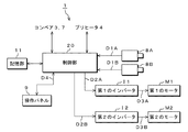
次に、自動はんだ付け装置1の制御系の構成例について説明する。図5に示すように、自動はんだ付け装置1は、記憶部11、制御部20、第1のインバータ(以下、インバータI1という)及び第2のインバータ(以下、インバータI2)を備える。制御部20は、コンベア3,7、プリヒータ4、操作パネル9、記憶部11、ロータリエンコーダ8A,8B及びインバータI1,I2に接続される。
次に、自動はんだ付け装置1の制御系の構成例について説明する。図5に示すように、自動はんだ付け装置1は、記憶部11、制御部20、第1のインバータ(以下、インバータI1という)及び第2のインバータ(以下、インバータI2)を備える。制御部20は、コンベア3,7、プリヒータ4、操作パネル9、記憶部11、ロータリエンコーダ8A,8B及びインバータI1,I2に接続される。
記憶部11には、コンベア3,7の搬送速度、プリヒータ4の加熱温度、噴流はんだ槽5の温度及びノズル52A,52Bからのはんだ噴流量のデータ等が記憶される。前述の操作パネル9に表示されるデータ選択ボタンA10(図3参照)を押すと、上述の各種データが呼び出される。
制御部20は、記憶部11に記憶された各種データを読み込んで操作パネル9に表示させる。制御部20は、操作パネル9に表示されるコンベア設定ボタンA1及びプリヒータ設定ボタンA2,A3,A4,A5によって設定されたコンベア3,7の搬送速度及びプリヒータ4の設定温度でコンベア3,7及びプリヒータ4を駆動する。
また、制御部20は、操作パネル9に表示される噴流設定ボタンA7,A8によって設定されたはんだの噴流量の情報を受信して、インバータI1,I2にその噴流量に基づく周波数を有する交流電圧を出力する。例えば、この交流電圧の周波数は、0Hzから50Hzであり、前述の噴流設定ボタンA7,A8で設定されるはんだの噴流量の0%から100%に対応している。つまり、噴流設定ボタンA7,A8で設定されるはんだの噴流量が40%のとき、交流電圧の周波数が20Hzとなる。
インバータI1にはモータM1が接続され、インバータI2にはモータM2が接続される。インバータI1,I2は、周波数変換を行う。インバータI1,I2は、制御部20から出力された交流電圧を受信して、その交流電圧をモータM1,M2を駆動させる周波数を有する交流電圧に変換してからモータM1,M2に出力する。モータM1,M2は、インバータI1,I2から出力された交流電圧で回転駆動して、噴流設定ボタンA7,A8によって設定されたはんだの噴流量でノズル52A,53Bからはんだを噴流させる。
ノズル52A,53Bからはんだが噴流されたことを前提に、操作パネル9に表示される手動噴流調整ボタンA9が押されると、制御部20は、噴流設定ボタンA7,A8によって設定されたはんだの噴流量を調整するための要求である調整要求D4を受け付けて、ロータリエンコーダ8A,8Bの操作を有効にする。ロータリエンコーダ8Aは、操作が有効にされて当該ロータリエンコーダ8Aが操作されると調整量情報D1Aを制御部に出力する。ロータリエンコーダ8Bは、操作が有効にされて当該ロータリエンコーダ8Bが操作されると調整量情報D1Bを制御部20に出力する。
制御部20は、ロータリエンコーダ8A,8Bから出力された調整量情報D1A,D1Bを受信して、噴流設定ボタンA7,A8によって設定されたモータM1,M2の回転数に対応した交流電圧の周波数を、調整量情報D1A,D1Bに応じた周波数で演算して、交流電圧D2A,D2Bを生成する。例えば、噴流設定ボタンA7ではんだの噴流量を40%に設定したとき、制御部20は、周波数20Hzを有する交流電圧を生成する。例えば、ロータリエンコーダ8Aを時計回りに回して周波数を2Hz変化させるようにすると、調整量情報D1Aは「+2Hz」という情報になる。制御部20が当該情報を受信して、20Hz+2Hzの演算処理を行い、周波数が22Hzである交流電圧D2Aを生成する。
制御部20は、生成した交流電圧D2A,D2BをインバータI1,I2に出力する。インバータI1,I2は、制御部20から出力された交流電圧D2A,D2Bを受信して、交流電圧D2A,D2BをモータM1,M2を駆動させる周波数を有する交流電圧D3A,D3Bに変換してからモータM1,M2に出力する。モータM1,M2は、インバータI1,I2から出力された交流電圧D3A,D3Bで回転駆動して、ロータリエンコーダ8A,8Bによって調整されたはんだの噴流量でノズル52A,53Bからはんだを噴流させる。
[制御部20の構成例]
次に制御部20の構成例を説明する。制御部20は、CPU21、ROM22、RAM23、第1のI/O(以下、I/O24という)、第2のI/O(以下、I/O25という)及びシステムバス26で構成される。
次に制御部20の構成例を説明する。制御部20は、CPU21、ROM22、RAM23、第1のI/O(以下、I/O24という)、第2のI/O(以下、I/O25という)及びシステムバス26で構成される。
CPU21は、I/O24に接続される。また、CPU21は、ROM22、RAM23及びI/O25にシステムバス26を介して接続される。I/O24は、コンベア3,7、プリヒータ4、操作パネル9、記憶部11及びインバータI1,I2に接続される。I/O25は、ロータリエンコーダ8A,8Bに接続される。
ROM22には、自動はんだ付け装置1を起動させるためのプログラムである起動プログラムが予め記憶される。CPU21は、自動はんだ付け装置1の電源をONにすると、ROM22に記憶される起動プログラムを読み出して、自動はんだ付け装置1を起動させる。CPU21は、操作パネル9で設定されたコンベア3,7の搬送速度、プリヒータ4の加熱温度、噴流はんだ槽5の温度及びはんだの噴流量で、コンベア3,7、プリヒータ4及び噴流はんだ槽5を駆動させる。CPU21は、操作パネル9に表示される手動噴流調整ボタンA9が押されると、調整要求D4を受信してI/O25からの出力を許可する。RAM23は、操作パネル9で設定されたはんだの噴流量の情報を記憶する。
I/O24には、コンベア3,7の速度センサで測定された搬送速度の情報、プリヒータ4の温度センサで測定された温度の情報、噴流はんだ槽5の温度センサで測定された温度の情報、操作パネル9で設定される各はんだ処理の設定情報及び記憶部11に記憶される各はんだ処理の設定情報が入力され、当該I/O24はそれらをCPU21に出力する。
また、I/O24は、CPU21から出力される、コンベア3,7を所望の搬送速度で駆動させる駆動情報、プリヒータ4を所望の温度に加熱する駆動情報、操作パネル9に各種データを表示させる表示情報及び各はんだ処理の設定のデータをコンベア3,7、プリヒータ4、操作パネル9及び記憶部11にそれぞれ出力する。I/O25は、CPU21から出力される調整要求D4によりロータリエンコーダ8A,8Bの操作を有効にする。I/O25は、調整要求D4を受信しない場合には、ロータリエンコーダ8A,8Bの操作を無効にする。
[自動はんだ付け装置1の動作例]
次に、自動はんだ付け装置1の動作例について説明する。図7に示すように、ステップST1では、自動はんだ付け装置1の電源をONにすると、CPU21は、ROM22に予め記憶される自動はんだ付け装置1を起動させるためのプログラムを読み出す。CPU21は、I/O24を介して操作パネル9に図3に示した表示例を表示させる表示情報を出力して、操作パネル9に運転画面を表示させる。
次に、自動はんだ付け装置1の動作例について説明する。図7に示すように、ステップST1では、自動はんだ付け装置1の電源をONにすると、CPU21は、ROM22に予め記憶される自動はんだ付け装置1を起動させるためのプログラムを読み出す。CPU21は、I/O24を介して操作パネル9に図3に示した表示例を表示させる表示情報を出力して、操作パネル9に運転画面を表示させる。
操作パネル9のデータ選択ボタンA10が押されると、記憶部11に格納された各種はんだ処理データが読み出され、当該操作パネルにそのデータが表示される。表示されたデータより所望のデータを選択すると、所望のデータが選択されたことがCPU21に出力されて、記憶部11から所望の各種はんだ処理データが読み出される。その読み出された各種はんだ処理データは、設定値として操作パネル9のコンベア設定ボタンA1、プリヒータ設定ボタンA2,A3,A4,A5、はんだ槽設定ボタンA6、噴流設定ボタンA7,A8の上側に数値として表示される。
ステップST2に移行して、操作パネル9に表示されるはんだ槽設定ボタンA6の上側の数値を押すと、図4に示したように、テンキーB1が表示される。例えば、テンキーB1にて「2」「2」「5」「ENT」を押すと、噴流はんだ槽5に収容されるはんだの温度が225℃に設定される。はんだの設定温度を決定した後、はんだ槽設定ボタンA6上側の「はんだ槽」を押すと、設定された温度(例えば、225℃)ではんだが加熱される。
ステップST3に移行して、CPU21は、はんだが設定された温度に到達したか否かを噴流はんだ槽5に設けられた温度センサからの出力によって判断する。はんだが設定された温度に到達して、所定の時間だけ経過していれば、操作パネル9の噴流可/噴流不可表示A11に「噴流可」が表示される(ステップST4)。はんだが設定された温度に到達していなければ、操作パネル9の噴流可/噴流不可表示A11に「噴流不可」が表示され、再度ステップST3に戻って、噴流はんだ槽5に収容されるはんだの温度を監視し続ける。
ステップST5に移行して、CPU21は、噴流設定ボタンA7,A8で設定されたはんだの噴流量の情報をRAM23に記憶させる。また、CPU21は、図3に示した噴流設定ボタンA7,A8の上部の「1次噴流」、「2次噴流」を押すと、噴流設定ボタンA7,A8で設定されたはんだの噴流量でポンプ部56を駆動してはんだを圧送させる。圧送されたはんだはノズル52A,52Bから噴流される。
ステップST6に移行して、操作パネル9に表示される手動噴流調整ボタンA9が押されると、噴流設定ボタンA7,A8によって設定されたはんだの噴流量を調整するための要求である調整要求D4がCPU21に出力される。CPU21は、調整要求D4を受信したか否かを判断する。調整要求D4を受信するとステップST7に移行する。調整要求D4を受信しなければ、ステップST10に移行する。
ステップST7では、CPU21は、噴流はんだ槽5に設けられたロータリエンコーダ8A,8Bの操作を有効にするためにI/O25からのロータリエンコーダ8A,8Bの出力を許可する。
ステップST8に移行して、ノズル52A,52Bから噴流されるはんだを調整するためにロータリエンコーダ8A,8Bを操作すると、当該ロータリエンコーダ8A,8Bから出力される調整量情報D1A,D1Bが、I/O25を介してCPU21に入力される。CPU21は、I/O25を介してロータリエンコーダ8A,8Bから出力された調整量情報D1A,D1Bに応じた交流電圧の周波数に変換して、その変換された周波数と噴流設定ボタンA7,A8より設定されてRAM23に記憶されたはんだの噴流量に対応する交流電圧の周波数とを演算して交流電圧D2A,D2Bを生成する。
ステップST9に移行して、CPU21は、生成された交流電圧D2A,D2BをI/O24を介してインバータI1,I2に出力する。インバータI1,I2は、交流電圧D2A,D2BをモータM1,M2が駆動される周波数を有する交流電圧D3A,D3Bに変換して、交流電圧D3A,D3BをモータM1,M2に出力する。モータM1,M2は、インバータI1,I2から出力された交流電圧D3A,D3Bで回転駆動して、ロータリエンコーダ8A,8Bによって調整されたはんだの噴流量でノズル52A,53Bからはんだを噴流させる。
また、ステップST10では、CPU21は、噴流はんだ槽5に設けられたロータリエンコーダ8A,8Bの操作を無効にするためにI/O25からのロータリエンコーダ8A,8Bの出力を禁止する。このため、ロータリエンコーダ8A,8Bを操作してもI/O25に調整量情報D1A,D1Bを入力することができない。この場合、再度ステップST6に戻って、CPU21は、調整要求D4の受信を待つ。
このように、本実施の形態に係る自動はんだ装置1によれば、ポンプ部56は、はんだを噴流する噴流はんだ槽5に設けられ、所定の噴流量ではんだを噴流する。操作パネル9は、ポンプ部56によって噴流されるはんだの噴流量を設定する。手動噴流調整ボタンA9は、操作パネル9によって設定されたはんだの噴流量を調整するための要求である調整要求D4を受け付ける。ロータリエンコーダ8A,8Bは、噴流はんだ槽5に設けられ、手動噴流調整ボタンA9によって受け付けられた調整要求D4に基づいてポンプ部56が噴流するはんだの噴流量を設定する。
これを前提にして、制御部20は、手動噴流調整ボタンA9によって調整要求D4が受け付けられると、操作パネル9により設定されたはんだの噴流量にロータリエンコーダ8A,8Bにより設定されたはんだの噴流量を演算して、当該演算されたはんだの噴流量をポンプ部56に出力する。
これにより、手動噴流調整ボタンA9によって調整要求D4が受け付けられると、操作パネル9により設定されたはんだの噴流量にロータリエンコーダ8A,8Bにより設定されたはんだの噴流量を演算して、当該演算されたはんだの噴流量をポンプ部56に出力するので、手動噴流調整ボタンA9による調整要求D4を制御部20が受け付けなければ、はんだの噴流量を増加させる方向に誤ってロータリエンコーダ8A,8Bを操作しても、噴流はんだ槽5からはんだが溢れ出ることを防止できる。この結果、自動はんだ付け装置1及びその周辺がはんだで汚染されることを防止できる。
なお、本実施の形態では、自動はんだ装置1について説明したが、モータ等の駆動手段を制御する駆動制御装置に対しても適用可能である。また、本実施の形態では、ロータリエンコーダ8Aを用いて、ノズル52Aから噴流されるはんだの噴流量を調整し、ロータリエンコーダ8Bを用いて、ノズル52Bから噴流されるはんだの噴流量を調整したが、ノズル52A及びノズル52Bから噴流されるはんだの噴流量の調整を切り替える切り替えスイッチを噴流はんだ槽5に設けて、1つのロータリエンコーダで調整してもよい。
本発明は、モータ等の駆動手段を制御する駆動制御装置、噴流はんだ槽及び自動はんだ付け装置に適用し極めて好適である。
1 自動はんだ付け装置
2 本体ケース
3 第2のコンベア
4 プリヒータ
5 噴流はんだ槽
6 冷却機
7 第1のコンベア
8A 第1のロータリエンコーダ
8B 第2のロータリエンコーダ
9 操作パネル
11 記憶部
20 制御部
2 本体ケース
3 第2のコンベア
4 プリヒータ
5 噴流はんだ槽
6 冷却機
7 第1のコンベア
8A 第1のロータリエンコーダ
8B 第2のロータリエンコーダ
9 操作パネル
11 記憶部
20 制御部
Claims (6)
- 所定の駆動量で駆動する駆動部と、
前記駆動部によって駆動される駆動量を設定する第1の設定部と、
前記第1の設定部によって設定された駆動量を調整するための要求である調整要求を受け付ける調整受付部と、
前記調整受付部によって受け付けられた前記調整要求に基づいて前記駆動部の駆動量を設定する第2の設定部と、
前記調整受付部によって前記調整要求が受け付けられると、前記第1の設定部により設定された駆動量に第2の設定部により設定された駆動量を演算して、当該演算された駆動量を前記駆動部に出力する制御部を備えることを特徴とする駆動制御装置。 - 前記第2の設定部にはロータリエンコーダが使用されることを特徴とする請求項1に記載の駆動制御装置。
- 所定の噴流量ではんだを噴流する噴流部と、
前記噴流部によって噴流されるはんだの噴流量を設定する第1の設定部と、
前記第1の設定部によって設定されたはんだの噴流量を調整するための要求である調整要求を受け付ける調整受付部と、
前記調整受付部によって受け付けられた前記調整要求に基づいて前記噴流部のはんだの噴流量を設定する第2の設定部と、
前記調整受付部によって前記調整要求が受け付けられると、前記第1の設定部により設定されたはんだの噴流量に第2の設定部により設定されたはんだの噴流量を演算して、当該演算されたはんだの噴流量を前記噴流部に出力する制御部を備えることを特徴とする噴流はんだ槽。 - 前記第2の設定部にはロータリエンコーダが使用されることを特徴とする請求項3に記載の噴流はんだ槽。
- はんだを噴流する噴流はんだ槽に設けられ、所定の噴流量で前記はんだを噴流する噴流部と、
前記噴流部によって噴流されるはんだの噴流量を設定する第1の設定部と、
前記第1の設定部によって設定されたはんだの噴流量を調整するための要求である調整要求を受け付ける調整受付部と、
前記噴流はんだ槽の近傍に設けられ、前記調整受付部によって受け付けられた前記調整要求に基づいて前記噴流部のはんだの噴流量を設定する第2の設定部と、
前記調整受付部によって前記調整要求が受け付けられると、前記第1の設定部により設定されたはんだの噴流量に第2の設定部により設定されたはんだの噴流量を演算して、当該演算されたはんだの噴流量を前記噴流部に出力する制御部を備えることを特徴とする自動はんだ付け装置。 - 前記第2の設定部にはロータリエンコーダが使用されることを特徴とする請求項5に記載の自動はんだ付け装置。
Applications Claiming Priority (2)
| Application Number | Priority Date | Filing Date | Title |
|---|---|---|---|
| JP2009015869A JP5332655B2 (ja) | 2009-01-27 | 2009-01-27 | 噴流はんだ槽及び自動はんだ付け装置 |
| JP2009-015869 | 2009-01-27 |
Publications (1)
| Publication Number | Publication Date |
|---|---|
| WO2010087343A1 true WO2010087343A1 (ja) | 2010-08-05 |
Family
ID=42395604
Family Applications (1)
| Application Number | Title | Priority Date | Filing Date |
|---|---|---|---|
| PCT/JP2010/050983 Ceased WO2010087343A1 (ja) | 2009-01-27 | 2010-01-26 | 駆動制御装置、噴流はんだ槽及び自動はんだ付け装置 |
Country Status (2)
| Country | Link |
|---|---|
| JP (1) | JP5332655B2 (ja) |
| WO (1) | WO2010087343A1 (ja) |
Citations (2)
| Publication number | Priority date | Publication date | Assignee | Title |
|---|---|---|---|---|
| JPH1071466A (ja) * | 1996-08-30 | 1998-03-17 | Nihon Dennetsu Kk | はんだ付け装置 |
| JPH10193095A (ja) * | 1997-01-06 | 1998-07-28 | Nitsuku:Kk | 半田付け条件検索装置及び自動半田付け装置 |
-
2009
- 2009-01-27 JP JP2009015869A patent/JP5332655B2/ja active Active
-
2010
- 2010-01-26 WO PCT/JP2010/050983 patent/WO2010087343A1/ja not_active Ceased
Patent Citations (2)
| Publication number | Priority date | Publication date | Assignee | Title |
|---|---|---|---|---|
| JPH1071466A (ja) * | 1996-08-30 | 1998-03-17 | Nihon Dennetsu Kk | はんだ付け装置 |
| JPH10193095A (ja) * | 1997-01-06 | 1998-07-28 | Nitsuku:Kk | 半田付け条件検索装置及び自動半田付け装置 |
Also Published As
| Publication number | Publication date |
|---|---|
| JP2010177289A (ja) | 2010-08-12 |
| JP5332655B2 (ja) | 2013-11-06 |
Similar Documents
| Publication | Publication Date | Title |
|---|---|---|
| JP5526957B2 (ja) | はんだ付け装置 | |
| JP5312584B2 (ja) | 噴流半田付け装置および半田付け方法 | |
| JP5910784B1 (ja) | 噴流ノズル及び噴流はんだ付け装置 | |
| US20070039999A1 (en) | Soldering apparatus and soldering method | |
| US8205783B2 (en) | Soldering apparatus | |
| JP5583304B2 (ja) | 噴流ノズル清掃装置、はんだ付け装置および噴流ノズル清掃方法 | |
| US20250256342A1 (en) | Method of processing substrate using jet soldering apparatus | |
| JP2019030884A (ja) | 噴流はんだ槽及び噴流はんだ付け装置 | |
| JP5332655B2 (ja) | 噴流はんだ槽及び自動はんだ付け装置 | |
| JP4978723B2 (ja) | はんだ付け装置 | |
| JP2010177289A5 (ja) | ||
| JP3562217B2 (ja) | 自動ハンダ付け装置 | |
| CN116745056A (zh) | 软钎料处理装置 | |
| JP3133582B2 (ja) | 電子部品自動装着装置 | |
| JP7609687B2 (ja) | 搬送加熱装置及び検出装置 | |
| JP4405848B2 (ja) | 電子部品装着方法及び電子部品装着装置 | |
| JP2007281271A (ja) | 半田加熱装置及び方法 | |
| JP3146802B2 (ja) | リフロー装置の立下げ方法 | |
| JP2003042665A (ja) | 熱処理装置、熱処理システム、熱処理方法、熱処理条件設定プログラム及びこのプログラムを記録したコンピュータ読みとり可能な記録媒体 | |
| JPH08236919A (ja) | プリント基板のイナートガスはんだリフロー装置 | |
| JP2004048044A (ja) | 部品実装方法および装置 | |
| JP2025097093A (ja) | 搬送爪及びはんだ付け装置 | |
| KR200158883Y1 (ko) | 집적회로의 솔더링 공정시 보이드 제거장치 | |
| JPH03135100A (ja) | 電子部品の自動装着装置 | |
| JP2025004274A (ja) | はんだ付け装置 |
Legal Events
| Date | Code | Title | Description |
|---|---|---|---|
| 121 | Ep: the epo has been informed by wipo that ep was designated in this application |
Ref document number: 10735811 Country of ref document: EP Kind code of ref document: A1 |
|
| NENP | Non-entry into the national phase |
Ref country code: DE |
|
| 122 | Ep: pct application non-entry in european phase |
Ref document number: 10735811 Country of ref document: EP Kind code of ref document: A1 |