WO2010084882A1 - 多軸駆動装置 - Google Patents
多軸駆動装置 Download PDFInfo
- Publication number
- WO2010084882A1 WO2010084882A1 PCT/JP2010/050636 JP2010050636W WO2010084882A1 WO 2010084882 A1 WO2010084882 A1 WO 2010084882A1 JP 2010050636 W JP2010050636 W JP 2010050636W WO 2010084882 A1 WO2010084882 A1 WO 2010084882A1
- Authority
- WO
- WIPO (PCT)
- Prior art keywords
- shaft
- shifter
- clutch
- motor
- drive device
- Prior art date
- Legal status (The legal status is an assumption and is not a legal conclusion. Google has not performed a legal analysis and makes no representation as to the accuracy of the status listed.)
- Ceased
Links
Images










Classifications
-
- B—PERFORMING OPERATIONS; TRANSPORTING
- B60—VEHICLES IN GENERAL
- B60N—SEATS SPECIALLY ADAPTED FOR VEHICLES; VEHICLE PASSENGER ACCOMMODATION NOT OTHERWISE PROVIDED FOR
- B60N2/00—Seats specially adapted for vehicles; Arrangement or mounting of seats in vehicles
- B60N2/02—Seats specially adapted for vehicles; Arrangement or mounting of seats in vehicles the seat or part thereof being movable, e.g. adjustable
- B60N2/0224—Non-manual adjustments, e.g. with electrical operation
- B60N2/02246—Electric motors therefor
-
- B—PERFORMING OPERATIONS; TRANSPORTING
- B60—VEHICLES IN GENERAL
- B60N—SEATS SPECIALLY ADAPTED FOR VEHICLES; VEHICLE PASSENGER ACCOMMODATION NOT OTHERWISE PROVIDED FOR
- B60N2/00—Seats specially adapted for vehicles; Arrangement or mounting of seats in vehicles
- B60N2/02—Seats specially adapted for vehicles; Arrangement or mounting of seats in vehicles the seat or part thereof being movable, e.g. adjustable
- B60N2/0296—Central command actuator to selectively switch on or engage one of several special purpose circuits or mechanisms
-
- B—PERFORMING OPERATIONS; TRANSPORTING
- B60—VEHICLES IN GENERAL
- B60N—SEATS SPECIALLY ADAPTED FOR VEHICLES; VEHICLE PASSENGER ACCOMMODATION NOT OTHERWISE PROVIDED FOR
- B60N2/00—Seats specially adapted for vehicles; Arrangement or mounting of seats in vehicles
- B60N2/02—Seats specially adapted for vehicles; Arrangement or mounting of seats in vehicles the seat or part thereof being movable, e.g. adjustable
- B60N2/04—Seats specially adapted for vehicles; Arrangement or mounting of seats in vehicles the seat or part thereof being movable, e.g. adjustable the whole seat being movable
- B60N2/06—Seats specially adapted for vehicles; Arrangement or mounting of seats in vehicles the seat or part thereof being movable, e.g. adjustable the whole seat being movable slidable
- B60N2/067—Seats specially adapted for vehicles; Arrangement or mounting of seats in vehicles the seat or part thereof being movable, e.g. adjustable the whole seat being movable slidable by linear actuators, e.g. linear screw mechanisms
-
- B—PERFORMING OPERATIONS; TRANSPORTING
- B60—VEHICLES IN GENERAL
- B60N—SEATS SPECIALLY ADAPTED FOR VEHICLES; VEHICLE PASSENGER ACCOMMODATION NOT OTHERWISE PROVIDED FOR
- B60N2/00—Seats specially adapted for vehicles; Arrangement or mounting of seats in vehicles
- B60N2/02—Seats specially adapted for vehicles; Arrangement or mounting of seats in vehicles the seat or part thereof being movable, e.g. adjustable
- B60N2/04—Seats specially adapted for vehicles; Arrangement or mounting of seats in vehicles the seat or part thereof being movable, e.g. adjustable the whole seat being movable
- B60N2/16—Seats specially adapted for vehicles; Arrangement or mounting of seats in vehicles the seat or part thereof being movable, e.g. adjustable the whole seat being movable height-adjustable
- B60N2/1605—Seats specially adapted for vehicles; Arrangement or mounting of seats in vehicles the seat or part thereof being movable, e.g. adjustable the whole seat being movable height-adjustable characterised by the cinematic
- B60N2/161—Rods
-
- B—PERFORMING OPERATIONS; TRANSPORTING
- B60—VEHICLES IN GENERAL
- B60N—SEATS SPECIALLY ADAPTED FOR VEHICLES; VEHICLE PASSENGER ACCOMMODATION NOT OTHERWISE PROVIDED FOR
- B60N2/00—Seats specially adapted for vehicles; Arrangement or mounting of seats in vehicles
- B60N2/02—Seats specially adapted for vehicles; Arrangement or mounting of seats in vehicles the seat or part thereof being movable, e.g. adjustable
- B60N2/22—Seats specially adapted for vehicles; Arrangement or mounting of seats in vehicles the seat or part thereof being movable, e.g. adjustable the back-rest being adjustable
Definitions
- the present invention relates to a multi-axis drive device that drives a plurality of output shafts with a single motor suitable for application to, for example, an electric seat for vehicles.
- the vehicle seat can be adjusted to the position and position of the occupant by adjusting the position of multiple locations, such as sliding in the entire longitudinal direction, vertical movement of the seating surface, or reclining of the seat back (backrest). Many of these formats are used.
- the adjustment of these movable parts was performed manually, but as a more convenient one, an electric seat that is adjusted by motor drive is provided.
- the electromagnetic clutches described in Patent Documents 1 and 2 are disadvantageous in terms of weight reduction.
- the clutches described in Patent Documents 3 and 4 contribute to weight reduction and cost reduction because they are mechanical, but because the motor is used to select the output shaft, further weight reduction and cost are achieved. Reduction is desired.
- An object of the present invention is to provide a multi-axis drive device.
- a multi-axis drive device is a motor having a motor shaft, a plurality of output shafts, and a connection means provided for each of the output shafts, and connecting the output shaft and the motor shaft.
- a manual operation member that selectively connects at least one of these connection means to the output shaft, the operation member is provided to slide in one direction, and the connection means includes: The operation members are arranged along the sliding direction.
- a multi-axis drive device including a motor having a motor shaft, a plurality of output shafts, and a connection for connecting the output shaft and the motor shaft. And a manual operation member that selectively connects at least one of these connection means to the output shaft, and the operation member is provided to be rotatable about an arbitrary rotation shaft.
- the connecting means is arranged along a circumferential direction along the rotation direction of the operation member.
- connection means is engaged with the motor shaft and is disposed concentrically with the shifter shaft for transmitting rotation of the motor shaft, A plurality of annular intermediate gears connected to the output shaft, and intermediate gear protrusions projecting from the inner peripheral surfaces of the intermediate gears, and the operating member relatively moves the shifter shaft and the intermediate gears Shift means for axially moving the shifter shaft into each intermediate gear and projecting on the peripheral surface of the shifter shaft, and when the shifter shaft is inserted into the intermediate gear, And a shifter protrusion that engages at least one intermediate gear protrusion of each intermediate gear protrusion in the circumferential direction and transmits the rotation of the shifter shaft to the intermediate gear.
- the motor power that is, rotation of the motor shaft
- the shifter shaft is transferred from the shifter shaft to the output shaft via the intermediate gear.
- a plurality of the shifter protrusions are provided on the shifter shaft, and all or at least one of the shifter protrusions is engaged with the intermediate gear protrusion.
- the shifter shaft and the intermediate gear protrusion may be prevented from interfering with one or both of the shifter protrusion and the intermediate gear protrusion in the axial direction, and the shaft of the shifter shaft. It is preferable that interference avoiding means for urging movement in the direction is provided.
- the motor when the shifter shaft is inserted into the intermediate gear, the motor is operated to rotate the motor shaft, whereby the shifter protrusion and the It is preferable that control to avoid interference in the axial direction of the intermediate gear protrusion is performed.
- connection means is constituted by a clutch mechanism that is brought into a non-connected state by a clutch non-connection holding member, and the output shaft is in a rotation state when in the connected state
- the operation member is disposed in a state of facing the clutch mechanism, and is rotated to be positioned at an operating position corresponding to at least one of the clutch mechanisms, and the clutch mechanism is connected at the operating position. It includes a form having a clutch connecting member to be in a state.
- the clutch connecting member is provided on the operating member, and the clutch mechanism is connected and disconnected by rotating the operating member, and the output shaft is connected to the output shaft.
- a movable part adjusting mechanism provided in a predetermined movable mechanism is connected, and the operation member is provided with a switch for operating the motor, and the switch is provided at a position suitable for the movable direction of the movable part. It is provided and the operation direction of this switch includes the form adapted to the movable direction of the movable part.
- the multi-axis drive device includes a mode in which the movable mechanism is a vehicle seat, and the output shaft is connected to an adjustment mechanism of a movable part of the vehicle seat.
- the clutch non-connection holding member includes a cam member that interlocks with the operation member or an elastic member.
- a manual rotation type second operation member is connected to the operation member via a transmission member, and the clutch mechanism is disconnected by the second operation member. Includes a form of performing a contact operation.
- the mechanism for branching the power of the motor to the plurality of output shafts and the selection of the output shaft to be operated are all achieved by the mechanical action.
- a plurality of output shafts can be driven.
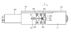
- FIG. 4 is a view taken in the direction of arrow J in FIG. 3. It is a K arrow line view of FIG. It is a front view of the intermediate gear of a multi-axis drive device. It is a side view explaining the operation
- FIG. 16 is a cross-sectional view taken along line LL in FIG.
- FIG. 16 is an MM arrow view of FIG. It is a side view which shows the usage example of the multi-axis drive device of 2nd Embodiment.
- It is a partial cross section front view of the multi-axis drive device of 3rd Embodiment which is a modification of 2nd Embodiment.
- It is a partial cross section front view of the multi-axis drive device of 4th Embodiment which is a modification of 2nd Embodiment.
- It is N arrow line view of FIG.
- It is a partial cross section front view of the multi-axis drive device of 5th Embodiment which is a modification of 2nd Embodiment.
- It is a partial cross section front view of the multi-axis drive device of 6th Embodiment which is a modification of 2nd Embodiment.
- FIG. 24 is a cross-sectional view taken along the line PP in FIG. 23.
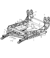
- FIGS. 1 and 2 show a vehicle electric motor to which the multi-axis drive device 9 of the first embodiment is applied. A part of the frame structure of the seat is shown.
- reference numeral 1 is a pair of left and right seat rails extending in the front-rear direction (in the accompanying drawings, arrow F indicates the front of the vehicle.
- directions such as the front-rear direction and the left-right direction are directions based on the vehicle. Define).
- These seat rails 1 are fixed to a vehicle body frame (not shown).
- a seat side frame 2 is mounted on each seat rail 1. These seat side frames 2 are movable along the seat rail 1 in the front-rear direction.
- a plate-shaped seat surface frame (not shown) is disposed between the seat side frames 2.
- the seat frame is supported by each seat side frame 2 via an electric seat surface vertical movement mechanism 7.
- the seat surface frame is moved up and down by the seat surface up-and-down moving mechanism 7, and the height of the seat surface of the seat is adjusted accordingly.
- the seat back bracket 3 is attached to the rear end portion of each seat side frame 2 via an electric reclining mechanism 6 so that the seat back bracket 3 can be tilted in the front-rear direction, that is, reclining.
- a lower end portion of a seat back side frame (not shown) constituting the seat back (backrest) is fixed to the seat back bracket 3.
- the reclining angle of the seat back is adjusted by the reclining mechanism 6.
- the seat side frames 2 are moved along the seat rail 1 by the front / rear slide mechanism 5 so that the front / rear position of the entire electric seat is adjusted.
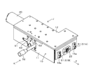
- the multi-axis drive device 9 according to the first embodiment is disposed inside the seat side frame 2 of one of the left and right seat side frames 2 (in this case, the right side of the vehicle). Hereinafter, the multi-axis drive device 9 will be described.
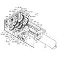
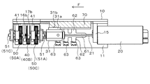
- the multi-axis drive device 9 is provided with a housing 10, a motor 20 fixed to the housing 10, and a housing 10.
- a shifter shaft 30, a plurality of (in this case, three) intermediate gears 40, and an output gear 50 that meshes with each intermediate gear 40 are provided.
- the housing 10 has a side plate 11 that is close to the seat side frame 2 and is parallel to the seat side frame 2, and an upper plate 12 that is fixed to the upper end of the side plate 11.
- a pair of front and rear bearing plates 13 and 14 parallel to each other are fixed to the front portion of the lower surface of the top plate 12.
- a motor support bracket 15 is fixed to the rear portion of the lower surface of the top plate 12.
- a motor 20 capable of forward / reverse rotation control is fixed to the outer surface (rear surface) of the motor support bracket 15.
- a motor shaft 21, which is a drive shaft of the motor 20, extends into the housing 10 in parallel with the front-rear direction, and a tip portion is rotatably supported by a front bearing plate 13 via a bearing 22.
- a plurality of (in this case, three) annular intermediate gears 40 are arranged coaxially with the motor 20 axis and at equal intervals. That is, the motor shaft 21 passes through the inside of each intermediate gear 40 coaxially.
- Each intermediate gear 40 is rotatably supported by a bearing 41 fixed to the top plate 12.
- An output gear 50 is engaged with these intermediate gears 40.
- the intermediate gear 40 is defined as the first intermediate gear 40A, the second intermediate gear 40B, and the third intermediate gear 40C from the front side, and the output gears 50 that mesh with the intermediate gears 40A, 40B, and 40C are respectively the first output gear 50A.
- the second output gear 50B and the third output gear 50C are respectively the first output gear 50A.
- the first output gear 50 ⁇ / b> A and the third output gear 50 ⁇ / b> C are disposed on the left side of the motor shaft 21, and the second output gear 50 ⁇ / b> B is
- Each output gear 50A, 50B, 50C has an output shaft 51 (first output shaft 51A, second output shaft 51B, third output shaft 51C) extending in the front-rear direction parallel to each other.
- the first output shaft 51 ⁇ / b> A is rotatably supported by a bearing 16 a fixed to the front bearing plate 13 and a bearing 16 b fixed to the lower surface of the top plate 12.
- the third output shaft 51C is rotatably supported by a bearing 17a fixed to the rear bearing plate 14 and a bearing 17b fixed to the lower surface of the top plate 12.
- the second output shaft 51B is rotatably supported by bearings 18a fixed to the front and rear bearing plates 13 and 14.
- the first torque cable 52A is connected to the protruding end portion of the first output shaft from the front bearing plate 13.
- a third torque cable 52C is connected to the protruding end portion of the third output shaft 51C from the rear bearing plate 14.
- the second output shaft 51B protrudes from the front and rear bearing plates 13 and 14, and a second torque cable 52B is connected to each of these protruding ends (the torque cables 52A, 52B, and 52C are shown in FIG. 1). And FIG. 2).
- the torque cables 52A, 52B, 52C transmit the rotation of the output shaft 20 to the seat surface vertical movement mechanism 7, the front / rear slide mechanism 5, and the reclining mechanism 6, respectively, to operate these mechanisms 5-7. is there.
- the first torque cable 52 ⁇ / b> A is connected to the seat surface vertical movement mechanism 7
- the two second torque cables 52 ⁇ / b> B are connected to the front / rear slide mechanism 5
- the third torque cable 52 ⁇ / b> C is connected to the reclining mechanism 6. .
- a sleeve-like shifter shaft 30 is inserted into the outer periphery of the motor shaft 21.
- the shifter shaft 30 is movable with respect to the motor shaft 21 in the axial direction of the motor shaft 21 by means such as spline coupling and is engaged with the motor shaft 21 so as not to rotate relative thereto. That is, the shifter shaft 30 rotates integrally with the motor shaft 21.
- a lever (shift means) 32 is attached to the end of the shifter shaft 30 on the motor 20 side via a joint 31.
- the lever 32 extends in a direction perpendicular to the motor shaft 21 and penetrates the side plate 11 of the housing 10.
- the joint 31 is attached to the shifter shaft 30 so as to be rotatable and not to move in the axial direction.
- the lever 32, the joint 31, and the shifter shaft 30 move integrally along the motor shaft 21 in the front-rear direction.
- an opening 2a is formed in the right seat part side frame 2, and the lever 32 protrudes from this opening.
- An occupant moves the shifter shaft 30 by operating the tip of the lever 32.
- the lever 32 passes through a slit 61 formed in the side plate 11 and extending in the front-rear direction.
- the lever 32 is movable in the front-rear direction in the slit 61, and in this state, the vertical position of the lever 32 is set to a substantially horizontal neutral position.
- the joint 31 incorporates a biasing member (not shown) that biases the lever 32 in the direction in which the vertical direction of the lever 32 is always returned to the neutral position.
- a guide block 70 is fixed to the lower surface of the top plate 12.
- a lower surface 71 of the guide block 70 is formed in a cross-sectional arc shape extending in the front-rear direction, and a front-rear guide groove 72 extending in the front-rear direction is formed at the apex of the lower surface 71.
- guide ridges 31 a that are slidably engaged with the front and rear guide grooves 72 are formed on the upper surface of the joint 31, and the guide ridges 31 a are front and rear in the joint 31 and the shifter shaft 30.
- the grooves 73 ⁇ / b> C are formed at the same interval as the arrangement interval of the intermediate gear 40.
- These upper and lower guide grooves 73 A to 73 C are formed along the circumferential direction of the lower surface 71 and are deeper than the front and rear guide grooves 72.
- a spherical pin 31b urged so as to protrude from the upper surface of the guide ridge 31a by an urging member (not shown) is attached to a predetermined portion of the guide ridge 31a of the joint 31. Yes.
- the pin 31b protrudes from the guide protrusion 31a and is engaged with any of the upper and lower guide grooves 73A to 73C. Match.
- a person operating the lever 32 can feel a click.
- the side plate 11 has a groove 62 communicating with the slit 61 and allowing the lever 32 to move up and down at a position corresponding to the lever 32. That is, three of these grooves 62 are formed above and below the slit 61.
- a switch 63 that is turned on when the lever 32 moved upward and downward contacts the inner surface of the side plate 11 and in the vicinity of the tip of each groove 62. .
- the motor 20 rotates.
- the motor 20 is set to rotate forward when the upper switch 63 is turned ON, and the motor 20 is rotated reversely when the upper switch 63 is turned ON.
- each switch 63 When the lever 32 is moved upward or downward along the groove, each switch 63 is turned on.
- the lever 32 rotates together with the joint 31 and returns to the neutral position.
- the pin 31b In this state, the pin 31b is engaged with the intersection of the upper and lower guide grooves 73A (73B, 73C) and the front and rear guide grooves 72. From this state, the lever 32 is moved back and forth against the force of the biasing member of the pin 31b. By moving in the direction, the shifter shaft 30 is moved in the front-rear direction.
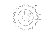
- a shifter protrusion 33 protruding in the radial direction is provided on the peripheral surface of the end portion of the shifter shaft 30 on the intermediate gear 40 side.
- an intermediate gear protrusion 43 is provided on the inner peripheral surface of each intermediate gear 40 so that the shifter protrusion 33 can be engaged in the circumferential direction.
- the shifter projection 33 When the pin 31b is engaged with the second upper and lower guide groove 73B, the shifter projection 33 is positioned inside the second intermediate gear 40B and can be engaged with the intermediate gear projection 43 of the second intermediate gear 40B in the circumferential direction. Become. Further, when the pin 31b is engaged with the third upper and lower guide groove 73C, the shifter protrusion 33 is positioned inside the third intermediate gear 40C and can be engaged with the intermediate gear protrusion 43 of the third intermediate gear 40C in the circumferential direction. Become.
- the shifter projection 33 interferes with the intermediate gear projection 43 and the shifter shaft 30 is less likely to move in the axial direction. It is possible to become. Therefore, in the present embodiment, as shown in FIG. 9, the front and rear end portions of both the shifter projection 33 and the intermediate gear projection 43 have an R surface (interference avoiding means) whose width becomes narrower toward the front end and the rear end. 33a and 43a are formed respectively.
- FIG. 9 shows the case where the shifter shaft 30 is moving forward, but the same behavior occurs when the shifter shaft 30 is moved backward so that the shifter shaft 30 can come out of the intermediate gear 40. Yes.
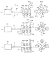
- FIG. 10 is a drawing schematically showing main parts of the multi-axis drive device 9.
- the lever 32 is operated to move the shifter shaft 30 forward as indicated by the arrow F, and the shifter shaft 30 is moved to the intermediate gear 40. 40 is inserted inside.
- FIG. 10B shows a state in which the shifter projection 33 is positioned inside the first intermediate gear 40A. At this time, the pin 31b is engaged with the first vertical guide groove 73A.
- the seat surface vertical movement mechanism 7 to which the first torque cable 52A is connected operates, and the height position of the seat surface of the seat is adjusted.
- the rotation direction of the motor 20 may be set so that the seat surface is raised when the lever 32 is raised and the seat surface is lowered when the lever 32 is lowered.
- FIG. 10 shows a case where the height position of the seat surface is adjusted. If the shifter protrusion 33 is positioned inside the second intermediate gear 40B and the same operation is performed, the rotation of the motor 20 is changed from the second intermediate gear 40B. It is transmitted to the second torque cable 52B via the second output gear 50B and the second output shaft 51B, and the front / rear slide mechanism 5 is operated to adjust the front / rear position of the entire seat. Further, if the shifter projection 33 is positioned inside the third intermediate gear 40C and the same operation is performed, the rotation of the motor 20 passes through the third output gear 50C and the third output shaft 51C from the third intermediate gear 40C to generate the third torque. It is transmitted to the cable 52C, and the reclining mechanism 6 is operated to adjust the reclining angle of the seat back.
- the shifter shaft 30 operated by the lever 32 is inserted into the intermediate gear 40 and the shifter protrusion 33 is engaged with the intermediate gear protrusion 43.
- the power of the motor 20, that is, the rotation of the motor shaft 21 can be transmitted from the shifter shaft 30 to the output shaft 51 via the intermediate gear 40.
- the power of one motor 20 can be selectively transmitted to the plurality of output shafts 51 without using a clutch as in the prior art.
- the number of parts of the structure can be reduced and the structure can be simplified, thereby reducing the weight and cost.
- FIG. 11 shows an example in which the shifter protrusion 33 can be tilted to a certain extent in the circumferential direction.
- a V-shaped notch 34 is formed at the tip of the shifter shaft 30 when viewed from the axial direction.
- the notch 34 is open to the end surface and the peripheral surface of the shifter shaft 30, and a rotary shaft 35 coaxial with the shaft center of the shifter shaft 30 is rotatably incorporated at the bottom thereof.
- a shifter protrusion 33 is integrally provided on the rotating shaft 35.
- the shifter protrusion 33 rotates integrally with the rotary shaft 35 between the circumferential inner surfaces 34 a and 34 b of the notch 34.
- the rotation angle of the shifter projection 33 is, for example, about 40 to 60 °.
- a torsion coil spring 36 is attached to the rotary shaft 35, and the torsion coil spring 36 biases the shifter protrusion 33 so that it is always positioned at the center in the circumferential direction of the notch 34.
- the shifter projection 33 tilts to one side in the circumferential direction, and interference is avoided.
- the movement of the shifter shaft 30 is not hindered, and the shifter protrusion 33 can be engaged with the intermediate gear protrusion 43 in the circumferential direction.
- the shifter protrusion 33 is tilted downward by a two-dot chain line.
- the shifter protrusion 33 is in one of the circumferential directions (in FIG. Or a2 direction).
- the shifter projection 33 is not only tilted in the circumferential direction but also tilted in the axial direction indicated by arrows b1 and b2 in FIG. 11A, or can be tilted flexibly in all directions. It may be. The wider the tiltable direction is, the more easily the shifter projection 33 in contact with the intermediate gear projection 43 tilts, and there is an advantage that interference is more easily avoided.
- FIG. 12 shows an example in which three shifter projections 33 are provided on the shifter shaft 30 so as to be arranged at equal intervals in the axial direction.
- the shifter projections 33 on both sides are positioned inside the two adjacent intermediate gears 40 (40A, 40B, 40C), and the output shafts connected to these intermediate gears 40 can be driven simultaneously.
- a plurality of shifter protrusions 33 are provided, and the position and number of shifter protrusions 33 are arbitrarily set according to which output shaft is driven.
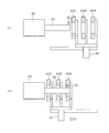
- the shifter shaft 30 can be moved in the axial direction relative to the motor shaft 21, but the shifter shaft 30 is integrated with the motor shaft 21. It is also possible to adopt a configuration that engages with and does not move in the axial direction. In that case, as shown in FIG. 13, the motor 20 is provided so as to be movable in the axial direction, and the lever 32 fixed to the motor 20 is operated to move the motor 20 and the shifter shaft 30 together to shift the shifter. The shaft 30 is inserted into the intermediate gear 40. Further, as shown in FIG. 14, a configuration is provided in which the shifter shaft 30 is inserted into the intermediate gear 40 by being provided so as to be movable in the axial direction at once and moving the intermediate gear 40 with the lever 32. May be.
- FIGS. 15 to 17 show a multi-axis drive device according to a second embodiment.
- the apparatus also includes a seat surface vertical movement mechanism that adjusts the height of the seat seat surface, a reclining mechanism that adjusts the angle of the seat back portion, and the front-rear position of the seat.
- a seat surface vertical movement mechanism that adjusts the height of the seat seat surface
- a reclining mechanism that adjusts the angle of the seat back portion
- the front-rear position of the seat For the three movable mechanisms of the front / rear slide mechanism for adjusting the power, it is preferable that the power of one motor 110 rotating in the forward and reverse directions is selectively branched to operate these movable mechanisms.
- the motor 110 has one end surface from which the motor shaft 111 protrudes fixed to the frame 1A.
- the motor shaft 11 passes through the frame 1A, and an input gear 112 is fixed to the tip thereof.
- the direction AB is a direction parallel to the motor shaft 111.
- three clutch gears 121 constituting a clutch mechanism (connection means) 120 are arranged concentrically with the motor shaft 111 as a center. These clutch gears 121 are formed concentrically at the end of the bearing sleeve 122 on the A direction side.
- a bearing hole 122a is formed through the center of the bearing sleeve 122.
- the bearing sleeve 122 is rotatably supported by the frame 1 ⁇ / b> A in a state where the axial direction is parallel to the motor shaft 111.
- Each clutch gear 121 meshes with the input gear 112. Therefore, when the motor 110 is operated and the motor shaft 111 rotates, the rotation is transmitted to the bearing sleeve 122 via the input gear 112 and the clutch gear 121.
- the clutch gears 121 are arranged at equal intervals, that is, every 90 ° within a circumferential angle of 180 °.
- An output shaft 125 having a circular cross section is penetrated through the bearing hole 122a of the bearing sleeve 122 so as not to move in the axial direction and to be slidably rotatable relative to the bearing sleeve 122.
- a disk-shaped clutch plate 126 that constitutes the clutch mechanism 120 is rotatable integrally with the output shaft 125 via a joint portion 125b. It is attached to be movable in the axial direction (AB direction).
- As the joint part 125b D-cut coupling by spigot fitting with a D-shaped cross section, spline coupling, or the like is employed.
- the clutch plate 126 is concentric with the output shaft 125, and the outer peripheral surface thereof is formed in a tapered shape having an isosceles triangle cross section whose thickness decreases toward the outer side in the radial direction.
- a click hole 127 is formed at the center of the end surface on the surface side of the clutch plate 126.
- the opposing surfaces of the clutch gear 121 and the clutch plate 126 are friction surfaces 121 a and 126 a, respectively.
- the friction surface 126 a of the clutch plate 126 becomes the friction surface of the clutch gear 121. It comes into contact with 121a.
- the dial 130 is disposed opposite to each clutch gear 121 with each clutch plate 126 interposed therebetween.
- the dial 130 has a rotation shaft 131 that is coaxial with the motor shaft 111 and extends in the direction of arrow B at the center.
- the rotation shaft 131 is rotatably supported by a frame or the like (not shown).
- a plurality of (in this case, two) pushers (clutch connecting members) 132 are incorporated in the back surface of the dial 130 facing the clutch plate 126 so as to be movable back and forth in the AB direction. These pushers 132 are always urged in the B direction by a coil spring 133 attached to the dial 130.
- the pusher 132 has a tapered shape that is slightly reduced in diameter toward the tip, and the tip surface is formed in a hemispherical shape.
- the two pushers 132 are arranged at positions where the circumferential angles around the rotation shaft 131 of the dial 130 are separated from each other by 135 ° (an angle indicated by ⁇ 1).
- each pusher 132 due to the rotation of the dial 130 coincides with a concentric circle about the motor shaft 111 passing through the center of each clutch plate 126.
- the tip end portion rides on the tapered surface 126 b on the dial 130 side of the clutch plate 126, and when further rotated, the pusher 132 is pushed by the coil spring 133 and clicked. 127 is fitted.
- the clutch plate 126 is pushed in the B direction by the pusher 132 biased by the coil spring 133, and the friction surface 126 a presses the friction surface 121 a of the clutch gear 121.
- a disc-shaped cam (clutch non-connection holding member, cam member) 140 is concentrically fixed to the tip of the rotary shaft 131 of the dial 130.
- the cam 140 that rotates integrally with the dial 130 is disposed at a position corresponding to the tapered surface 126c on the bearing sleeve 122 side of the clutch plate 126, and the tapered surface 140a formed on the clutch plate 126 side on the outer peripheral edge
- the friction surface 126a of the clutch plate 126 is separated from the friction surface 121a of the clutch gear 121, and the disconnected state of the clutch mechanism 120 is maintained. Yes.
- a defect 141 that avoids interference in the AB direction with the clutch plate 126 is formed at a location corresponding to each pusher 132 on the outer peripheral edge of the cam 140.
- Tapered surfaces 141 a are formed at both ends of the arc-shaped edge that forms the defect 141.
- a rectangular parallelepiped switch 150 for selecting ON / OFF of the motor 110 and the rotation direction of the motor 110 is attached to the surface of the dial 130.
- the switch 150 is regulated so as to slide to both sides in the longitudinal direction of the switch 150 (CD direction in FIG. 15A) and to stop at an intermediate point of the sliding range by an urging member (not shown).
- the switch 150 extends through the center point of the dial 130, and one end thereof is in a state of protruding outward from the dial 130.
- the protruding end is configured as an instruction unit 151.
- the switch 150 has a circumferential angle of 45 ° ( ⁇ 2) from the clockwise pusher 132 in which the instruction unit 151 is between the two pushers 132 in the figure.
- the angle shown) is attached to the dial 130 in a state of being arranged at a separated position.
- the pusher on the side closer to the instruction unit 151 of the switch 150 is referred to as a first pusher 132a
- the pusher on the far side is referred to as a second pusher 132b.
- the motor 110 is turned off at a neutral point in a stopped state that does not move in the longitudinal direction.
- the motor 110 is operated such that the motor 110 rotates in the forward direction when slid in the C direction and the motor 110 rotates in the reverse direction when slid in the D direction.
- the multi-axis drive device is arranged on the side surface of the seat cushion where the occupant seated on the seat cushion can operate the dial 130, the motor shaft 111 extends in the left-right direction of the vehicle body, and the three clutches Of the mechanisms 120, the middle clutch mechanism 120 is located below, one of the other two clutch mechanisms 120 is forward (direction F in FIG. 18), and the other clutch mechanism 120 is rearward. Attach to each position.
- the clutch mechanism 120 is a first clutch mechanism 120A, a second clutch mechanism 120B, and a third clutch mechanism 120C in order from the front side.
- a torque cable (not shown) is connected to the output shaft 125 of each clutch mechanism 120A to 120C.
- the torque cable transmits the rotation of each output shaft 125 to a reclining mechanism that adjusts the angle of the seat back, a seat front and rear slide mechanism, and a seat surface vertical movement mechanism that adjusts the height of the seat. It is to be operated.
- the output shaft 125 of the first clutch mechanism 120A is a reclining mechanism
- the output shaft 125 of the second clutch mechanism 120B is a seat front / rear slide mechanism
- the output shaft 125 of the third clutch mechanism 120C is via a torque cable.
- Each is connected to the seat surface vertical movement mechanism.
- the motor 110 rotates so that when the switch 150 is slid forward (C direction), the entire seat moves forward, and when the switch 150 is slid backward (D direction), the entire seat moves backward. To do.
- the switch 150 By appropriately moving the switch 150 back and forth, the front / rear position of the seat can be adjusted to a desired position.
- the motor 110 rotates so that when the switch 150 is slid forward (C direction), the seat back is tilted forward, and when the switch 150 is slid rearward (D direction), the back is tilted backward.
- the backrest can be adjusted to a desired angle by moving the switch 150 up and down appropriately.
- the motor 110 rotates so that the seat seat surface is lowered when the switch 150 is slid downward (C direction), and the seat seat surface is raised when the switch 150 is slid upward (D direction).
- the switch 150 By appropriately moving the switch 150 up and down, the seat seat surface can be adjusted to a desired height.
- the mechanism for branching the power of the motor 110 to the plurality of output shafts 125 is the clutch gear 121 integrated with each output shaft 125 in the input gear 112. It is the structure of meshing.
- the output shaft 125 is selected by rotating the dial 130 and causing the pusher 132 provided on the dial 130 to act on the clutch mechanism 120 to be connected.
- the mechanism for branching the power of the motor 110 to the plurality of output shafts 125 and the selection of the output shaft 125 to be operated are all achieved by mechanical action.
- the number of members constituting the power transmission path (the input gear 112, the bearing sleeve 122 having the clutch gear 121, and the clutch plate 126 connected to and disconnected from the output shaft 125) is also small. For this reason, the structure is simple, and significant weight reduction and cost reduction can be achieved.
- the position and operation direction of the switch 150 in the state of being attached to the seat are adapted to the movable mechanism to be adjusted (the reclining mechanism, the front / rear slide mechanism, the seat surface vertical movement mechanism), Since the operation feeling and the actual operation are performed as expected, there is an advantage that it is excellent in usability.
- FIG. 19 shows a third embodiment of the present invention.
- a coil spring (clutch disconnection holding member, elastic member) 160 is used instead of the cam 140 as a member for separating the clutch plate 126 from the clutch gear 121.
- a coil spring (clutch disconnection holding member, elastic member) 160 is used instead of the cam 140 as a member for separating the clutch plate 126 from the clutch gear 121.
- a coil spring (clutch disconnection holding member, elastic member) 160 is used.
- a counterbore-shaped recess 122b is formed on the side of the clutch gear 121 of the bearing hole 122a of the bearing sleeve 122, and the coil spring 160 is compressed in a state wound around the output shaft 125 in the recess 122b.
- the coil spring 160 constantly urges the clutch plate 126 in the A direction, that is, the direction in which the clutch mechanism 120 is disconnected, whereby the clutch plate 126 is separated from the clutch gear 121 and the clutch mechanism 120 is in a disconnected state.
- the clutch plate 126 When the dial 130 rotates and the pusher 132 rides on the clutch plate 126, the clutch plate 126 is pushed by the pusher 132 against the elastic force of the coil spring 160 and moves in the B direction, and the friction surface 126a moves to the clutch gear.
- the clutch mechanism 120 is in a connected state with the friction surface 121a of 121 being pressed.
- FIG. 20 shows a fourth embodiment of the present invention.
- the rotating shaft of the motor 110 is installed in a state orthogonal to the rotating shaft of the input gear 112.
- two clutch mechanisms 120 including a bearing sleeve 122 meshing with the input gear 112 are provided.
- a first gear 111a constituting a bevel gear is fixed to the tip of the motor shaft 111 of the motor 110.
- an input shaft 113 extending in the B direction is fixed to the center of the input gear 112, and a first gear 111a and a second gear 113a constituting a bevel gear are fixed to the tip of the input shaft 113.
- the second gear 113a meshes with the first gear 111a on the motor 110 side.
- the output shaft 125 is not attached to each clutch plate 126 and is a separate body.
- the clutch plate 126 is coaxially formed with a shaft portion 126d instead of the output shaft 125.
- the shaft portion 126d is axially connected to the coil spring 160 built in the recess 122b of the bearing sleeve 122. It is inserted freely.
- the bearing sleeve 122 is not formed with a hole through which the output shaft 125 penetrates as in the third embodiment.
- a gear 126e is formed on the outer peripheral surface of the clutch plate 126 of the fourth embodiment.
- the output shaft 125 is rotatably supported in parallel with the clutch plate 126 and the bearing sleeve 122 in a state parallel to the moving direction of each clutch plate 126 (the axial direction of the shaft portion 126d).
- An output gear 125 ⁇ / b> A is integrally fixed to one end portion of the output shaft 125, and the output gear 125 ⁇ / b> A meshes with the gear 126 e on the outer peripheral surface of the clutch plate 126.
- the rotation of the motor shaft 111 is transmitted from the first gear 111a of the bevel gear to the second gear 113a so that the input gear 112 rotates and meshes with the input gear 112.
- the bearing sleeve 122 is always rotating.
- the dial 130 is rotated and the clutch plate 126 is pushed in the B direction by the pusher 132 and the clutch mechanism 120 is in the connected state
- the rotation of the bearing sleeve 122 is transmitted to the clutch plate 126 and rotates integrally.
- the output gear 125A meshing with the gear 126e of the rotating clutch plate 126 rotates, and the output shaft 125 to which the output gear 125A is fixed rotates.
- FIG. 22 shows a fifth embodiment of the present invention.
- the motor 110 is disposed at a position between the input gear 112 and the dial 130 as shown in the figure, and the input shaft 113 is extended in the A direction.
- the first gear 111a of the motor shaft 111 is meshed with the second gear 113a at the tip of the input shaft 113.
- the dimension in the direction AB of FIG. 22 is smaller than that in FIG. 20, and thus the size is reduced, and thus the degree of freedom in design is increased.
- FIG. 23 shows a sixth embodiment of the present invention.
- the dial 130 (referred to as the first dial 130 in this embodiment) is rotated by another dial (second dial: second operation member). This is configured to perform connection / disconnection switching of the clutch mechanism 120 at 135.
- the first dial 130 is rotatably supported on one surface side (right side in FIG. 23) of the frame 170 via a rotating shaft 130a.
- the second dial 135 is rotatable on the other surface side (the left side in FIG. 23) of the frame 170 via the rotation shaft 135a at a non-coaxial position around the first dial 130. It is supported.
- a switch 150 ⁇ / b> A similar to the switch 150 is attached to the second dial 135.
- the frame 170 is a frame such as a seat frame when the present apparatus is applied to a movable vehicle seat as in the second embodiment.
- the rotation shaft 135a of the second dial 135 passes through the frame 170 and protrudes to one side.
- the rotation shaft 135a of the second dial 135 and the rotation shaft 130a of the first dial 130 are shown.
- a transmission belt (transmission member) 180 is wound around.
- the second dial 135 is rotated, the rotation is transmitted to the first dial 130 via the transmission belt 180, whereby the first dial 130 is rotated to switch connection / disconnection of the clutch mechanisms 120. Is called.
- the second dial 135 is arranged at an arbitrary position away from the first dial 130 and the dials 130 and 135 are connected by the transmission belt 180, whereby the clutch mechanisms 120 are connected.
- the connection / disconnection operation that is, the selection of the output shaft 125 to be driven can be performed at a position not restricted by the positions where the clutch mechanism 120 and the dial 130 are disposed. Therefore, the degree of freedom in design increases.
- one gear or a gear train in which a plurality of gears are engaged may be employed as a means for transmitting the rotation of the second dial 135 to the second dial 130.
- the number of pushers 132 acting on the clutch mechanism 120 by rotating the dial 130 is increased or decreased as necessary, and the rotation angle of the dial 130 is also shown.
- the arrangement angle of the clutch mechanism 120 connected and disconnected by the pusher 132 can be arbitrarily set.
- the number of output shafts is also arbitrary.
- the seat seat surface height is adjusted separately at two locations on the front and rear of the seat cushion. Is possible.
Landscapes
- Engineering & Computer Science (AREA)
- Aviation & Aerospace Engineering (AREA)
- Transportation (AREA)
- Mechanical Engineering (AREA)
- Seats For Vehicles (AREA)
Abstract
モータ軸(21)を有するモータ(20)と、モータ軸(21)に係合され、モータ軸(21)の回転が伝達するシフタ軸(30)と、シフタ軸(30)と同心状に配設された複数の環状の中間ギヤ(40)と、これら中間ギヤ(40)の内周面にそれぞれ突設された中間ギヤ突起(43)と、各中間ギヤ(40)に連結される出力軸(51)と、シフタ軸(30)と各中間ギヤ(40)とを相対的に軸方向に移動させ、シフタ軸(30)を各中間ギヤ(40)の内部に挿入させるシフト手段と、シフタ軸(30)の周面に突設され、シフタ軸(30)が中間ギヤ(40)の内部に挿入された時に、各中間ギヤ突起(43)のうちの少なくとも1つの中間ギヤ突起(43)に対し周方向に係合して、シフタ軸(30)の回転を中間ギヤ(40)に伝達するシフタ突起(33)を備える。簡素な構造により1つのモータで複数の出力軸を駆動することができ、軽量化やコスト低減が図られる。
Description
本発明は、例えば車両用電動シート等に適用されて好適な1つのモータで複数の出力軸を駆動する多軸駆動装置に関する。
車両用シートにあっては、全体の前後方向のスライドや座面高さの上下動、あるいはシートバック(背もたれ)のリクライニング等、複数箇所の位置を調節可能として、乗員の体形や姿勢に適合できるようにした形式のものが多い。これらの可動部位の調節は手動でなされるものであったが、より便利なものとして、モータ駆動により調節する電動シートが提供されている。
複数の可動部位をそれぞれ独立して駆動するには、可動部位に連結した各出力軸ごとにモータを1つ1つ連結させる構成が考えられるが、これではモータの数が多くなって不合理である。そこで、1つのモータで複数の出力軸を駆動すれば効率的であり、そのために、複数の可動部位に連結した各出力軸に、クラッチを介してモータの動力が伝達されるようにし、クラッチを断接して各可動部位を選択的に駆動するものが知られている(特許文献1~4参照)。
上記特許文献のうち、特許文献1,2に記載される電磁クラッチは、軽量化の面で不利である。この点、特許文献3,4に記載されるクラッチは、機械式であるため軽量化やコストの低減には寄与するが、出力軸の選択にモータを使用しているため、さらなる軽量化やコストの低減が望まれている。
よって本発明は、1つのモータで複数の出力軸を駆動するにあたり、機械式クラッチを効果的に組み合わせることにより構造を簡素とすることができ、結果として確実に軽量化やコスト低減を図ることができる多軸駆動装置の提供を目的としている。
本発明の請求項1に係る多軸駆動装置は、モータ軸を有するモータと、複数の出力軸と、これら出力軸ごとに設けられ、出力軸と前記モータ軸とを接続状態とする接続手段と、これら接続手段のうちの少なくとも1つを前記出力軸に対して選択的に接続させる手動式の操作部材とを備え、前記操作部材は、一方向にスライドするよう設けられ、前記接続手段は、該操作部材のスライド方向に沿って配列されていることを特徴としている。
また、本発明の請求項2に係る多軸駆動装置は、モータ軸を有するモータと、複数の出力軸と、これら出力軸ごとに設けられ、出力軸と前記モータ軸とを接続状態とする接続手段と、これら接続手段のうちの少なくとも1つを前記出力軸に対して選択的に接続させる手動式の操作部材とを備え、前記操作部材は、任意の回転軸を中心に回転自在に設けられ、前記接続手段は、該操作部材の回転方向に沿った周方向に沿って配列されていることを特徴としている。
上記請求項1に係る多軸駆動装置においては、前記接続手段は、前記モータ軸に係合され、該モータ軸の回転が伝達するシフタ軸と、このシフタ軸と同心状に配設され、前記出力軸に連結される複数の環状の中間ギヤと、これら中間ギヤの内周面にそれぞれ突設された中間ギヤ突起とを備え、前記操作部材は、前記シフタ軸と前記各中間ギヤとを相対的に軸方向に移動させ、シフタ軸を各中間ギヤの内部に挿入させるシフト手段と、前記シフタ軸の周面に突設され、該シフタ軸が前記中間ギヤの内部に挿入された時に、前記各中間ギヤ突起のうちの少なくとも1つの中間ギヤ突起に対し周方向に係合して、シフタ軸の回転を該中間ギヤに伝達するシフタ突起とを備える形態を含む。この形態によると、シフタ軸を中間ギヤの内部に挿入してシフタ突起を中間ギヤ突起に係合させることにより、モータの動力すなわちモータ軸の回転を、シフタ軸から中間ギヤを介して出力軸に伝達することができる。このため、従来のようにクラッチを用いる必要がなくなり、部品点数の減少に伴う構造の簡素化や軽量化が図られる。
また、上記請求項1に係る多軸駆動装置においては、前記シフタ突起は前記シフタ軸に複数設けられており、これらシフタ突起の全て、あるいは少なくとも1つが、前記中間ギヤ突起に係合する形態を含む。
また、上記請求項1に係る多軸駆動装置においては、前記シフタ突起と前記中間ギヤ突起の一方あるいは双方に、これらシフタ突起と中間ギヤ突起の軸方向への干渉を回避してシフタ軸の軸方向への移動を促す干渉回避手段が具備されていることを好ましい形態としている。
また、上記請求項1に係る多軸駆動装置においては、前記シフタ軸が前記中間ギヤの内部に挿入される時に、前記モータを稼働させて前記モータ軸を回転させることにより、前記シフタ突起と前記中間ギヤ突起の軸方向への干渉を回避する制御がなされることを好ましい形態としている。
次に、上記請求項2に係る多軸駆動装置においては、前記接続手段は、クラッチ非接続保持部材によって非接続状態とされ、接続状態の時に前記出力軸が回転状態となるクラッチ機構からなり、前記操作部材は、前記クラッチ機構に対向する状態に配置され、回転運動させられることにより、前記クラッチ機構のうちの少なくとも1つに対応する作用位置に位置付けられ、この作用位置において該クラッチ機構を接続状態とするクラッチ接続部材を有している形態を含む。
また、上記請求項2に係る多軸駆動装置においては、前記クラッチ接続部材は、前記操作部材に設けられ、該操作部材を回転させることにより前記クラッチ機構の断接がなされ、前記出力軸には、所定の可動機構が備える可動部位の調節機構が接続され、かつ、前記操作部材には前記モータを作動させるスイッチが設けられており、該スイッチは、前記可動部位の可動方向に適合する箇所に設けられるとともに、該スイッチの操作方向が、前記可動部位の可動方向に適合している形態を含む。
また、上記請求項2に係る多軸駆動装置においては、前記可動機構が車両用シートであり、該車両用シートが有する可動部位の調節機構に、前記出力軸が接続されている形態を含む。
また、上記請求項2に係る多軸駆動装置においては、前記クラッチ非接続保持部材は、前記操作部材と連動するカム部材であるか、あるいは弾性部材である形態を含む。
また、上記請求項2に係る多軸駆動装置においては、前記操作部材に、伝達部材を介して手動回転式の第2の操作部材を連結し、該第2の操作部材によって前記クラッチ機構の断接操作を行う形態を含む。
本発明によれば、モータの動力を複数の出力軸に分岐する機構や、作動させる出力軸の選択を、機械的な作用によって全て達成しており、このため、簡素な構造により1つのモータで複数の出力軸を駆動することができる。その結果、軽量化やコスト低減を図ることができるといった効果を奏する。
9…多軸駆動装置、20…モータ、21…モータ軸、30…シフタ軸、32…レバー(シフト手段)、33…シフタ突起、33a,43a…R面(干渉回避手段)、40…中間ギヤ、43…中間ギヤ突起、51…出力軸、110…モータ、120…クラッチ機構、125…出力軸、130…ダイヤル(操作部材)、131…回転軸、132…プッシャ(クラッチ接続部材)、135…第2のダイヤル(第2の操作部材)、140…カム(クラッチ非接続保持部材、カム部材)、150…スイッチ、160…コイルばね(クラッチ非接続保持部材、弾性部材)、180…伝達ベルト(伝達部材)。
以下、図面を参照して本発明の実施形態を説明する。
[1]第1実施形態
(1)第1実施形態の構成
(1-1)電動シートのフレーム構造
図1および図2は、第1実施形態の多軸駆動装置9が適用された車両用電動シートの、フレーム構造の一部を示している。これら図で符号1は前後方向に延びる左右一対のシートレールである(添付図面で矢印Fは車両の前方を指している、以下、前後方向および左右方向といった方向は、車両を元にした方向と定義する)。これらシートレール1は、図示せぬ車体フレームに固定される。各シートレール1には、座部サイドフレーム2がそれぞれ装着されている。これら座部サイドフレーム2は、シートレール1に沿って前後方向に移動可能とされている。
[1]第1実施形態
(1)第1実施形態の構成
(1-1)電動シートのフレーム構造
図1および図2は、第1実施形態の多軸駆動装置9が適用された車両用電動シートの、フレーム構造の一部を示している。これら図で符号1は前後方向に延びる左右一対のシートレールである(添付図面で矢印Fは車両の前方を指している、以下、前後方向および左右方向といった方向は、車両を元にした方向と定義する)。これらシートレール1は、図示せぬ車体フレームに固定される。各シートレール1には、座部サイドフレーム2がそれぞれ装着されている。これら座部サイドフレーム2は、シートレール1に沿って前後方向に移動可能とされている。
また、各座部サイドフレーム2間には、図示せぬプレート状の座面フレームが配設される。この座面フレームは、電動式の座面上下動機構7を介して各座部サイドフレーム2に支持される。座面フレームは座面上下動機構7によって上下動させられ、かつ、これによってシートの座面の高さ調節がなされるようになっている。
各座部サイドフレーム2の後端部には、電動式のリクライニング機構6を介してシートバックブラケット3が前後方向への傾動、すなわちリクライニングが可能に取り付けられている。これらシートバックブラケット3には、シートバック(背もたれ)を構成する図示せぬシートバックサイドフレームの下端部が固定される。シートバックはリクライニング機構6によってリクライニング角度の調節がなされるようになっている。
上記各座部サイドフレーム2は、前後スライド機構5によりシートレール1に沿って移動させられ、これによって当該電動シート全体の前後位置の調節がなされるようになっている。左右の座部サイドフレーム2のうちの一方(この場合、車両の右側に当たる方)の座部サイドフレーム2の内側に、第1実施形態に係る多軸駆動装置9が配設されている。以下、この多軸駆動装置9を説明する。
(1-2)多軸駆動装置の構成
多軸駆動装置9は、図3~図7に示すように、ハウジング10と、このハウジング10に固定されたモータ20と、ハウジング10内に設けられたシフタ軸30、複数(この場合、3つ)の中間ギヤ40および各中間ギヤ40に噛合する出力ギヤ50を備えている。
多軸駆動装置9は、図3~図7に示すように、ハウジング10と、このハウジング10に固定されたモータ20と、ハウジング10内に設けられたシフタ軸30、複数(この場合、3つ)の中間ギヤ40および各中間ギヤ40に噛合する出力ギヤ50を備えている。
ハウジング10は、座部サイドフレーム2に近接し、該座部サイドフレーム2と平行な側板11と、この側板11の上端部に固定される上板12とを有している。図4~図6に示すように、天板12の下面の前部には、互いに平行な前後一対の軸受プレート13,14が固定されている。また、天板12の下面の後部には、モータ支持ブラケット15が固定されている。モータ支持ブラケット15の外面(後側の面)には、正逆回転制御が可能なモータ20が固定されている。このモータ20の駆動軸であるモータ軸21は前後方向と平行でハウジング10内に延びており、先端部が前側の軸受プレート13に軸受22を介して回転自在に支持されている。
前後の軸受プレート13,14間には、複数(この場合、3つ)の環状の中間ギヤ40がモータ20軸と同軸的に、かつ、等間隔をおいて配設されている。すなわちモータ軸21は、各中間ギヤ40の内部を同軸的に貫通している。各中間ギヤ40は、それぞれ天板12に固定された軸受41に回転自在に支持されている。そしてこれら中間ギヤ40には出力ギヤ50が噛合されている。ここで、中間ギヤ40を前側から第1中間ギヤ40A、第2中間ギヤ40B、第3中間ギヤ40Cとし、これら中間ギヤ40A,40B,40Cに噛合する出力ギヤ50を、それぞれ第1出力ギヤ50A、第2出力ギヤ50B、第3出力ギヤ50Cとする。第1出力ギヤ50Aと第3出力ギヤ50Cはモータ軸21の左側に配置され、第2出力ギヤ50Bはモータ軸21の右側に配置されている。
各出力ギヤ50A,50B,50Cは、互いに平行な前後方向に延びる出力軸51(第1出力軸51A、第2出力軸51B、第3出力軸51C)を有している。図5に示すように、第1出力軸51Aは、前側軸受プレート13に固定された軸受16aと、天板12の下面に固定された軸受16bとに回転自在に支持されている。また、第3出力軸51Cは、後側軸受プレート14に固定された軸受17aと、天板12の下面に固定された軸受17bとに回転自在に支持されている。また、第2出力軸51Bは、前後の軸受プレート13,14に固定された軸受18aに回転自在に支持されている。
第1出力軸の前側軸受プレート13からの突出端部には第1トルクケーブル52Aが接続されている。また、第3出力軸51Cの後側軸受プレート14からの突出端部には第3トルクケーブル52Cが接続されている。また、第2出力軸51Bは、前後の軸受プレート13,14から突出しており、これら突出端部には、第2トルクケーブル52Bがそれぞれ接続されている(トルクケーブル52A,52B,52Cは図1および図2参照)。
上記各トルクケーブル52A,52B,52Cは、出力軸20の回転を、上記座面上下動機構7、前後スライド機構5およびリクライニング機構6にそれぞれ伝達して、これら機構5~7を動作させるものである。この場合、第1トルクケーブル52Aは座面上下動機構7に接続され、2つの第2トルクケーブル52Bは前後スライド機構5にそれぞれ接続され、第3トルクケーブル52Cはリクライニング機構6に接続されている。
さて、図5に示すように、モータ軸21の外周にはスリーブ状のシフタ軸30が挿通されている。このシフタ軸30はモータ軸21に対し、スプライン結合等の手段によって、モータ軸21の軸方向には移動自在で、かつ、モータ軸21とは相対回転不能に係合されている。すなわちシフタ軸30はモータ軸21と一体に回転する。シフタ軸30のモータ20側の端部にはジョイント31を介してレバー(シフト手段)32が取り付けられている。このレバー32はモータ軸21に直交する方向に延び、ハウジング10の側板11を貫通している。ジョイント31はシフタ軸30に回転可能、かつ、軸方向には動かないように取り付けられている。レバー32、ジョイント31およびシフタ軸30は、モータ軸21に沿って前後方向に一体に移動する。
図1に示すように、右側の座部サイドフレーム2には開口2aが形成されており、この開口からレバー32は突出している。乗員はこのレバー32の先端を操作してシフタ軸30を動かすようになっている。図3に示すように、レバー32は側板11に形成された前後方向に延びるスリット61を貫通している。レバー32はスリット61内を前後方向に移動可能とされ、この状態でレバー32の上下方向の位置はほぼ水平な中立位置とされる。ジョイント31には、レバー32の上下方向を常に中立位置に復帰させる方向に付勢する図示せぬ付勢部材が内蔵されている。レバー32によってシフタ軸30を前方に移動させると、シフタ軸30は、後側軸受プレート14のモータ軸21が貫通している孔を通って各中間ギヤ40の内部に挿入されるようになっている。
図4~図6に示すように、天板12の下面にはガイドブロック70が固定されている。このガイドブロック70の下面71は前後方向に延びる断面円弧状に形成されており、この下面71の頂点部には、前後方向に延びる前後ガイド溝72が形成されている。図6に示すように、ジョイント31の上面には、前後ガイド溝72に摺動自在に係合するガイド凸条31aが形成されており、ジョイント31およびシフタ軸30は、ガイド凸条31aが前後ガイド溝72に沿って移動することにより、前後方向への移動が案内される。
また、図5に示すように、ガイドブロック70の下面71には、前側から順に、前後ガイド溝72に直交して横断する第1上下ガイド溝73A、第2上下ガイド溝73B、第3上下ガイド溝73Cが、ちょうど中間ギヤ40の配置間隔と同じ間隔で形成されている。これら上下ガイド溝73A~73Cは、下面71の周方向に沿って形成されており、前後ガイド溝72よりも深いものである。
図6に示すように、ジョイント31のガイド凸条31aの所定箇所には、図示せぬ付勢部材によってガイド凸条31aの上面から突出するように付勢された球状のピン31bが装着されている。ジョイント31がシフタ軸30とともに前後方向に移動させられピン31bが上下ガイド溝73A~73Cとの交点に達すると、ピン31bはガイド凸条31aから突出して上下ガイド溝73A~73Cのいずれかに係合する。この時、レバー32を操作する者はクリック感を感じることができる。この状態から、レバー32を上方または下方に動かすと、ピン31bが上下ガイド溝73A(73B,73C)に沿って移動し、ジョイント31がモータ軸21の周囲を回動する。この時、レバー32、ジョイント31およびシフタ軸30の前後方向の移動は、ピン31bが上下ガイド溝ガイド73A(73B,73C)に係合していることにより規制される。
図7に示すように、側板11には、スリット61に連通し、レバー32の上下動を許容する溝62が、レバー32に対応する位置に形成されている。すなわちこれら溝62は、スリット61の上側および下側に3つずつ形成されている。図4~図6に示すように、側板11の内面であって、各溝62の先端近傍には、上方および下方に動かされるレバー32が接触することによりONとなるスイッチ63が取り付けられている。レバー32が接触してスイッチ63がONになると、モータ20が回転する。上側のスイッチ63がONになった時にはモータ20は正転し、上側のスイッチ63がONになった時にはモータ20は逆転するように設定されている。
レバー32を溝に沿って上方または下方に動かすと、各スイッチ63がONになり、この状態からレバー32を離すと、レバー32はジョイント31ごと回動して中立位置に戻る。この状態でピン31bは上下ガイド溝73A(73B,73C)と前後ガイド溝72との交点に係合しているが、この状態からピン31bの付勢部材の力に抗してレバー32を前後方向に動かすことにより、シフタ軸30は前後方向に移動させられる。そして、レバー32の前後方向への移動に伴ってピン31bが第1~第3上下ガイド溝73A~73Cのいずれかに係合することにより、シフタ軸30は、上記クリック感を伴って、次に説明する各中間ギヤ40に対応した所定の係合位置に位置決めされる。
シフタ軸30の中間ギヤ40側の端部の周面には、図8に示すように、径方向に突出するシフタ突起33が突設されている。一方、各中間ギヤ40の内周面には、シフタ突起33が周方向に係合可能とされる中間ギヤ突起43が突設されている。レバー32を前方に操作して上記ピン31bが第1上下ガイド溝73Aに係合した時、シフタ突起33は第1中間ギヤ40Aの内部に位置し、第1中間ギヤ40Aの中間ギヤ突起43と周方向に係合可能となる。この実施形態では、シフタ軸30、各中間ギヤ40および中間ギヤ突起43により、本発明の接続手段が構成されている。また、上記のレバー32およびシフタ突起33により、本発明の操作部材が構成されている。
そして、ピン31bが第2上下ガイド溝73Bに係合した時には、シフタ突起33は第2中間ギヤ40Bの内部に位置し、第2中間ギヤ40Bの中間ギヤ突起43と周方向に係合可能となる。さらに、ピン31bが第3上下ガイド溝73Cに係合した時には、シフタ突起33は第3中間ギヤ40Cの内部に位置し、第3中間ギヤ40Cの中間ギヤ突起43と周方向に係合可能となる。
シフタ軸30が前方に移動して中間ギヤ40の内部に挿入される際、あるいは後退する際に、シフタ突起33が中間ギヤ突起43に干渉し、それ以上シフタ軸30が軸方向に移動しにくくなることが考えられる。そこで本実施形態では、図9に示すように、シフタ突起33および中間ギヤ突起43の双方の前後端部に、先端および後端に向かうにしたがって幅が狭くなるようなR面(干渉回避手段)33a,43aを、それぞれ形成している。
これにより、図9(a)に示すようにシフタ突起33が中間ギヤ突起43に干渉した際、R面33a,43aどうしが摺接することにより図9(b)に示すようにシフタ軸30がいずれか一方に回転しながら軸方向に移動し、図9(c)に示すようにシフタ突起33は中間ギヤ突起43に対し周方向に係合が可能となる。図9はシフタ軸30が前方に移動している場合であるが、シフタ軸30が後方に移動する場合も同様の挙動が起こってシフタ軸30は中間ギヤ40から抜け出ることができるようになっている。
(2)第1実施形態の動作
続いて上記多軸駆動装置9の動作を説明する。
図10は、上記多軸駆動装置9の主要部を模式的に描いた図面である。図10(a)に示すように、シフタ軸30が中間ギヤ40に挿入されていない状態から、レバー32を操作してシフタ軸30を矢印Fで示す前方に移動させ、シフタ軸30を中間ギヤ40の内部に挿入させる。図10(b)はシフタ突起33が第1中間ギヤ40Aの内部に位置付けられた状態を示し、この時、上記ピン31bは第1上下ガイド溝73Aに係合していることになる。
続いて上記多軸駆動装置9の動作を説明する。
図10は、上記多軸駆動装置9の主要部を模式的に描いた図面である。図10(a)に示すように、シフタ軸30が中間ギヤ40に挿入されていない状態から、レバー32を操作してシフタ軸30を矢印Fで示す前方に移動させ、シフタ軸30を中間ギヤ40の内部に挿入させる。図10(b)はシフタ突起33が第1中間ギヤ40Aの内部に位置付けられた状態を示し、この時、上記ピン31bは第1上下ガイド溝73Aに係合していることになる。
この状態から、レバー32を上方、あるいは下方に動かすと、スイッチ63がONとなってモータ20のモータ軸21が回転する。すると、シフタ軸30が回転して図10(c)に示すようにシフタ突起33が中間ギヤ突起43に係合し、シフタ軸30の回転がシフタ突起33から中間ギヤ突起43を介して第1中間ギヤ40Aに伝わり、第1中間ギヤ40Aが回転する。第1中間ギヤ40Aが回転すると第1出力ギヤ50Aが回転するので第1出力軸51Aも回転し、その出力軸51Aに接続されている第1トルクケーブル52Aに動力が伝わる。これにより第1トルクケーブル52Aが接続されている座面上下動機構7が作動し、シートの座面の高さ位置が調節される。この場合には、レバー32を上げると座面が上がり、レバー32を下げると座面が下がるようにモータ20の回転方向を設定するとよい。
図10は座面の高さ位置を調節する場合を示しており、シフタ突起33を第2中間ギヤ40Bの内部に位置付けて同様の操作をすれば、モータ20の回転が第2中間ギヤ40Bから第2出力ギヤ50B、第2出力軸51Bを経て第2トルクケーブル52Bに伝わり、前後スライド機構5が作動してシート全体の前後位置が調節される。また、シフタ突起33を第3中間ギヤ40Cの内部に位置付けて同様の操作をすれば、モータ20の回転が第3中間ギヤ40Cから第3出力ギヤ50C、第3出力軸51Cを経て第3トルクケーブル52Cに伝わり、リクライニング機構6が作動してシートバックのリクライニング角度が調節される。
(3)作用効果
上記実施形態の多軸駆動装置9によれば、レバー32で操作されるシフタ軸30を中間ギヤ40の内部に挿入してシフタ突起33を中間ギヤ突起43に係合させることにより、モータ20の動力すなわちモータ軸21の回転を、シフタ軸30から中間ギヤ40を介して出力軸51に伝達することができる。このため、従来のようにクラッチを用いることなく、1つのモータ20の動力を複数の出力軸51に選択的に伝達することができる。その結果、構造の部品点数の低減や構造の簡素化が可能となり、もって軽量化ならびにコスト低減を図ることができる。
上記実施形態の多軸駆動装置9によれば、レバー32で操作されるシフタ軸30を中間ギヤ40の内部に挿入してシフタ突起33を中間ギヤ突起43に係合させることにより、モータ20の動力すなわちモータ軸21の回転を、シフタ軸30から中間ギヤ40を介して出力軸51に伝達することができる。このため、従来のようにクラッチを用いることなく、1つのモータ20の動力を複数の出力軸51に選択的に伝達することができる。その結果、構造の部品点数の低減や構造の簡素化が可能となり、もって軽量化ならびにコスト低減を図ることができる。
また、シフタ突起33と中間ギヤ突起43にR面33a,43aを形成することにより、軸方向に移動するシフタ突起33が中間ギヤ突起43に干渉してもシフタ軸30が軸方向に移動することができることは前述の如くであり、動作不良を招くおそれがない。
このような作用をより確実に起こさせるための形態として、シフタ突起33または中間ギヤ突起43のいずれか一方が周方向側に傾倒可能とされた形態は好ましいものとされる。図11は、シフタ突起33が周方向側にある程度の範囲で傾倒可能とされた例を示している。
この場合、シフタ軸30の先端部には、軸方向から見てV字状の切欠き34が形成されている。この切欠き34はシフタ軸30の端面および周面に開放しており、その底部には、シフタ軸30の軸心と同軸状である回転軸35が回転可能に組み込まれている。そしてこの回転軸35に、シフタ突起33が一体的に設けられている。シフタ突起33は、切欠き34の周方向の内面34a,34bの間を回転軸35と一体に回転する。シフタ突起33の回転角度は、例えば40~60°程度である。また、回転軸35にはねじりコイルばね36が装着されてり、このねじりコイルばね36により、シフタ突起33は、常に切欠き34の周方向中央に位置付けられるように付勢されている。
図11に示す形態によれば、シフタ軸30が軸方向に移動してシフタ突起33が中間ギヤ突起43に当接すると、シフタ突起33が周方向の一方側に傾倒して干渉が回避され、シフタ軸30の移動に支障は起こらず、シフタ突起33が中間ギヤ突起43に対し周方向に係合することが可能となる。図11ではシフタ突起33は下方に傾倒する状態を二点鎖線で示しているが、中間ギヤ突起43への当接の状況によってシフタ突起33は周方向のいずれか一方(図11で矢印a1方向かa2方向)に傾倒する。
なお、シフタ突起33は周方向側に傾倒するだけでなく、図11(a)の矢印b1,b2に示す軸方向側にも傾倒するか、あるいは制限なく全方向にフレキシブルに傾倒可能に構成されていてもよい。傾倒可能な方向が広い範囲になるほど、中間ギヤ突起43に当接したシフタ突起33は傾倒しやすく、干渉がより回避されやすいという利点がある。
なお、このようにシフタ突起33が中間ギヤ突起43に干渉することを実質的に防止する手段としては、この他に、レバー32、ジョイント31あるいはシフタ軸30の前後方向の移動を検知した時に、低速でモータ20を回転させるか、あるいはモータ20をごく短い時間回転させる寸動を行わせるといった制御を行うことによっても可能である。このようにモータ20を回転させることにより、シフタ軸30が回転してシフタ突起33が中間ギヤ突起43から周方向にずれ、シフタ軸30の軸方向の移動が可能となる。
(4)第1実施形態の変更形態
以下に、上記第1実施形態を基本構成とした変更例の形態を説明する。
(4-1)シフタ突起が複数ある形態
上記実施形態では、シフタ突起33はシフタ軸30に1つ設けられていたが、シフタ突起33は複数設けられていてもよい。図12は、シフタ軸30に3つのシフタ突起33が軸方向に等間隔に並んで突設されている例を示している。この場合には、両側のシフタ突起33が、隣接する2つの中間ギヤ40(40A,40B,40C)の内部に位置付けられ、これら中間ギヤ40に連結される出力軸を同時に駆動することができる。これは複数のシフタ突起33を設ける一例であり、シフタ突起33の形成位置や数は、どの出力軸を駆動するかに応じて任意に設定される。
以下に、上記第1実施形態を基本構成とした変更例の形態を説明する。
(4-1)シフタ突起が複数ある形態
上記実施形態では、シフタ突起33はシフタ軸30に1つ設けられていたが、シフタ突起33は複数設けられていてもよい。図12は、シフタ軸30に3つのシフタ突起33が軸方向に等間隔に並んで突設されている例を示している。この場合には、両側のシフタ突起33が、隣接する2つの中間ギヤ40(40A,40B,40C)の内部に位置付けられ、これら中間ギヤ40に連結される出力軸を同時に駆動することができる。これは複数のシフタ突起33を設ける一例であり、シフタ突起33の形成位置や数は、どの出力軸を駆動するかに応じて任意に設定される。
(4-2)シフタ軸と中間ギヤの相対移動形態
上記実施形態では、シフタ軸30をモータ軸21に対して相対的に軸方向に移動可能としているが、シフタ軸30をモータ軸21に一体に係合させて軸方向にも移動しないような構成を採用することもできる。その場合には、図13に示すように、モータ20を軸方向に移動自在に設け、モータ20に固定したレバー32を操作することにより、モータ20とシフタ軸30とを一体に移動させてシフタ軸30を中間ギヤ40の内部に挿入するといった形態になる。また、図14に示すように、一括して軸方向に移動自在に設けて、中間ギヤ40をレバー32で移動させて、シフタ軸30が中間ギヤ40の内部に挿入されるような形態を採ってもよい。
上記実施形態では、シフタ軸30をモータ軸21に対して相対的に軸方向に移動可能としているが、シフタ軸30をモータ軸21に一体に係合させて軸方向にも移動しないような構成を採用することもできる。その場合には、図13に示すように、モータ20を軸方向に移動自在に設け、モータ20に固定したレバー32を操作することにより、モータ20とシフタ軸30とを一体に移動させてシフタ軸30を中間ギヤ40の内部に挿入するといった形態になる。また、図14に示すように、一括して軸方向に移動自在に設けて、中間ギヤ40をレバー32で移動させて、シフタ軸30が中間ギヤ40の内部に挿入されるような形態を採ってもよい。
[2]第2実施形態
次に、本発明の第2実施形態を説明する。
(1)第2実施形態の構成
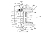
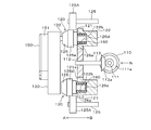
図15~図17は、第2実施形態に係る多軸駆動装置を示している。該装置も、上記第1実施形態と同様に、車両用電動シートの、シート座面の高さを調節する座面上下動機構、シート背もたれ部の角度を調節するリクライニング機構、およびシートの前後位置を調節する前後スライド機構の3つの可動機構に対し、正逆回転する1つのモータ110の動力を選択的に分岐させてこれら可動機構を作動させるものとして好適とされる。
次に、本発明の第2実施形態を説明する。
(1)第2実施形態の構成
図15~図17は、第2実施形態に係る多軸駆動装置を示している。該装置も、上記第1実施形態と同様に、車両用電動シートの、シート座面の高さを調節する座面上下動機構、シート背もたれ部の角度を調節するリクライニング機構、およびシートの前後位置を調節する前後スライド機構の3つの可動機構に対し、正逆回転する1つのモータ110の動力を選択的に分岐させてこれら可動機構を作動させるものとして好適とされる。
そのモータ110は、図15(b)に示すように、モータ軸111が突出する一端面がフレーム1Aに固定されている。モータ軸11はフレーム1Aを貫通し、その先端には、入力ギヤ112が固定されている。なお、図15(b),図16でA-B方向は、モータ軸111と平行な方向を示している。モータ軸111の周囲には、図17に示すように、クラッチ機構(接続手段)120を構成する3つのクラッチギヤ121が、モータ軸111を中心として同心状に配設されている。これらクラッチギヤ121は、軸受スリーブ122のA方向側の端部に同心状に形成されている。
図16に示すように、軸受スリーブ122の中心には軸受孔122aが貫通形成されている。軸受スリーブ122は、軸方向がモータ軸111と平行な状態で、フレーム1Aに回転自在に支持されている。そして各クラッチギヤ121が、入力ギヤ112に噛合している。したがってモータ110が運転されてモータ軸111が回転すると、その回転が入力ギヤ112、クラッチギヤ121を経て軸受スリーブ122に伝達する。本実施形態では、図17に示すように、各クラッチギヤ121は、周方向角度が180°の中で、等間隔、すなわち90°おきに配置されている。
軸受スリーブ122の軸受孔122aには、断面円形状の出力軸125が、軸方向には移動不能で、かつ、軸受スリーブ122と相対的に摺動回転可能に貫通されている。これら出力軸125の、クラッチギヤ121側の端部には、継手部125bを介して、クラッチ機構120を構成する円板状のクラッチプレート126が、出力軸125と一体的に回転可能、かつ、軸方向(A-B方向)に移動可能に取り付けられている。継手部125bとしては、断面D字状の凹凸嵌合によるDカット結合、もしくはスプライン結合等が採用される。クラッチプレート126は出力軸125と同心状で、その外周面は、径方向の外側に向かうにしたがって厚さが減じる断面二等辺三角形状のテーパ状に形成されている。また、クラッチプレート126の表面側の端面の中央には、クリック孔127が形成されている。
クラッチギヤ121とクラッチプレート126の互いの対向面は、それぞれ摩擦面121a,126aとなっており、クラッチプレート126がB方向に移動すると、該クラッチプレート126の摩擦面126aがクラッチギヤ121の摩擦面121aに当接するようになっている。
図15および図16の符号130は円板状のダイヤル(操作部材)である。このダイヤル130は、各クラッチギヤ121に対し、各クラッチプレート126を挟んで対向配置されている。ダイヤル130は、中心にモータ軸111と同軸的で矢印B方向に延びる回転軸131を有しており、この回転軸131が、図示せぬフレーム等に回転自在に支持されている。
ダイヤル130の、クラッチプレート126に面する裏面には、複数(この場合2つ)のプッシャ(クラッチ接続部材)132が、A-B方向に進退自在に組み込まれている。これらプッシャ132は、ダイヤル130に装着されたコイルばね133により常にB方向に付勢されている。このプッシャ132は、先端に向かうにしたがって僅かに縮径するテーパ状であって、先端面は半球面状に形成されている。2つのプッシャ132は、図15(a)に示すように、ダイヤル130の回転軸131を中心とした周方向角度が互いに135°(θ1で示す角度)離れた位置に配置されている。
ダイヤル130が回転することによる各プッシャ132の回転軌跡は、各クラッチプレート126の中心を通るモータ軸111を中心とした同心円に一致する。プッシャ132は、ダイヤル130を回転させることによって1つのクラッチプレート126に近付くと、先端部がそのクラッチプレート126のダイヤル130側のテーパ面126bに乗り上げ、さらに回転するとコイルばね133に押されてクリック孔127に嵌合する。このときクラッチプレート126はコイルばね133で付勢されているプッシャ132でB方向に押され、摩擦面126aがクラッチギヤ121の摩擦面121aを押圧した状態となる。
これがクラッチ機構120の接続状態であり、モータ110の回転はクラッチギヤ121からクラッチプレート126を介して出力軸125に伝わり、出力軸125が回転する。プッシャ132がクリック孔127に嵌合することにより操作時のクリック感を得ることができるとともに、ダイヤル130をクラッチ機構120の接続位置に確実に位置付けることができるようになっている。
また、図15および図17に示すように、ダイヤル130の回転軸131の先端には、円板状のカム(クラッチ非接続保持部材、カム部材)140が同心状に固定されている。ダイヤル130と一体回転するこのカム140は、クラッチプレート126の軸受スリーブ122側のテーパ面126cに対応する位置に配設されており、外周縁のクラッチプレート126側に形成されたテーパ面140aが、クラッチプレート126のテーパ面126cに乗り上げてA方向に押すことにより、クラッチプレート126の摩擦面126aはクラッチギヤ121の摩擦面121aから離間し、クラッチ機構120の切断状態が保持されるようになっている。
図17に示すように、カム140の外周縁の各プッシャ132に対応する箇所には、クラッチプレート126とのA-B方向の干渉を避ける欠損部141が形成されている。欠損部141を形成する円弧状の縁部の両端部には、テーパ面141aが形成されている。
この構成により、ダイヤル130を回転させて欠損部141内に1つのクラッチプレート126が位置すると、そのクラッチプレート126と一体の出力軸125はB方向に移動可能となり、この状態でプッシャ132がクラッチプレート126をB方向に押すことにより、クラッチ機構120が接続状態となる。一方、他の2つのクラッチプレート126はカム140によってクラッチギヤ121から離間し、クラッチ機構120が切断状態となる。そして、この状態からダイヤル130を回転させると、クラッチ機構120が接続状態であったクラッチプレート126のテーパ面126cに、欠損部141のテーパ面141aが摺接しながら乗り上げ、さらにカム140のテーパ面140aがクラッチプレート126のテーパ面126cに乗り上げてA方向に押すことにより、クラッチプレート126の摩擦面126aがクラッチギヤ121の摩擦面121aから離間してクラッチ機構120が切断される。
上記ダイヤル130の表面には、上記モータ110のON/OFF、およびモータ110の回転方向を選択するための直方体状のスイッチ150が取り付けられている。このスイッチ150は、自身の長手方向の両側(図15(a)でC-D方向)にスライドし、かつ、図示せぬ付勢部材によりスライド範囲の中間点で停止するように規制されている。スイッチ150はダイヤル130の中心点を通って延在しており、一端部はダイヤル130よりも外側に出た状態となっている。そしてその突出端が、指示部151として構成されている。
図15(a)に示すように、スイッチ150は、指示部151が2つのプッシャ132の間であって、同図で上方にある時計回り側のプッシャ132から周方向角度で45°(θ2で示す角度)離間した位置に配される状態に、ダイヤル130に取り付けられている。ここで、スイッチ150の指示部151に近い側のプッシャを第1プッシャ132a、遠い側のプッシャを第2プッシャ132bとする。
このスイッチ150によると、長手方向に移動しない停止状態の中立点ではモータ110はOFFとされる。そして、例えばC方向にスライドさせるとモータ110が正転し、D方向にスライドさせるとモータ110が逆転するというように、モータ110が運転される。
(2)第2実施形態の適用例および動作
以上が第2実施形態の多軸駆動装置の構成であり、続いて、図18を参照して該装置を車両用電動シートに適用した例を説明する。
以上が第2実施形態の多軸駆動装置の構成であり、続いて、図18を参照して該装置を車両用電動シートに適用した例を説明する。
まず、当該多軸駆動装置を、シートクッションの側面であって、該シートクッションに着座する乗員がダイヤル130を操作可能な箇所に、モータ軸111が車体の左右方向に延び、かつ、3つのクラッチ機構120のうちの、真ん中のクラッチ機構120が下方に位置し、他の2つのクラッチ機構120のうちの一方が前方(図18でF方向)に、また、もう一方のクラッチ機構120が後方にそれぞれ位置する状態に取り付ける。ここで、クラッチ機構120を、前側から順に第1クラッチ機構120A、第2クラッチ機構120B、第3クラッチ機構120Cとする。
各クラッチ機構120A~Cの出力軸125には、それぞれ図示せぬトルクケーブルが接続される。トルクケーブルは、各出力軸125の回転を、シート背もたれ部の角度を調節するリクライニング機構、シートの前後スライド機構、シートの高さを調節する座面上下動機構にそれぞれ伝達して、これら機構を作動させるものである。この場合、トルクケーブルを介して、第1クラッチ機構120Aの出力軸125はリクライニング機構に、第2クラッチ機構120Bの出力軸125はシートの前後スライド機構に、第3クラッチ機構120Cの出力軸125は座面上下動機構に、それぞれ接続される。以下、各機構を多軸駆動装置で作動させる方法を説明する。
(2-1)シートの前後スライド機構
前後スライド機構を作動させてシートの前後位置を調節するには、ダイヤル130を回転させて図18(a)に示すようにスイッチ150の指示部151を前方に向ける。すると、第2プッシャ132bが第2クラッチ機構120Bのクラッチプレート126のクリック孔127に嵌合して該クラッチプレート126がクラッチギヤ121を押圧し、第2クラッチ機構120Bが接続状態となる。一方、第1および第3クラッチ機構120A,20Cにおいては、カム140の作用でクラッチプレート126がクラッチギヤ121から離間することにより、切断状態が保持される。
前後スライド機構を作動させてシートの前後位置を調節するには、ダイヤル130を回転させて図18(a)に示すようにスイッチ150の指示部151を前方に向ける。すると、第2プッシャ132bが第2クラッチ機構120Bのクラッチプレート126のクリック孔127に嵌合して該クラッチプレート126がクラッチギヤ121を押圧し、第2クラッチ機構120Bが接続状態となる。一方、第1および第3クラッチ機構120A,20Cにおいては、カム140の作用でクラッチプレート126がクラッチギヤ121から離間することにより、切断状態が保持される。
この状態から、スイッチ150を前方(C方向)にスライドさせるとシート全体が前方に移動し、スイッチ150を後方(D方向)にスライドさせるとシート全体が後方に移動するように、モータ110が回転する。スイッチ150を適宜に前後に動かすことにより、シートの前後位置を所望の位置に調節することができる。
(2-2)リクライニング機構
リクライニング機構でシートの背もたれ角度を調節するには、ダイヤル130を回転させて図18(b)に示すようにスイッチ150の指示部151を前方、かつ斜め下方45°に向ける。すると、第1プッシャ132aが第1クラッチ機構120Aに作用して該第1クラッチ機構120Aが接続状態となる。一方、第2および第3クラッチ機構120B,20Cにおいては、カム140の作用でクラッチプレート126がクラッチギヤ121から離間することにより、切断状態が保持される。
リクライニング機構でシートの背もたれ角度を調節するには、ダイヤル130を回転させて図18(b)に示すようにスイッチ150の指示部151を前方、かつ斜め下方45°に向ける。すると、第1プッシャ132aが第1クラッチ機構120Aに作用して該第1クラッチ機構120Aが接続状態となる。一方、第2および第3クラッチ機構120B,20Cにおいては、カム140の作用でクラッチプレート126がクラッチギヤ121から離間することにより、切断状態が保持される。
この状態から、スイッチ150を斜め前方(C方向)にスライドさせるとシートの背もたれが前方に傾き、スイッチ150を斜め後方(D方向)にスライドさせると背もたれが後方に傾くように、モータ110が回転する。スイッチ150を適宜に上下させることにより、背もたれを所望角度に調節することができる。
(2-3)シートの座面上下動機構
座面高さ機構を作動させてシート座面の高さを調節するには、ダイヤル130を回転させて図18(c)に示すようにスイッチ150の指示部151を下方に向ける。すると、第2プッシャ132bが第3クラッチ機構120Cに作用して該第3クラッチ機構120Cが接続状態となる。一方、第1および第2クラッチ機構120A,20Bにおいては、カム140の作用でクラッチプレート126がクラッチギヤ121から離間することにより、切断状態が保持される。
座面高さ機構を作動させてシート座面の高さを調節するには、ダイヤル130を回転させて図18(c)に示すようにスイッチ150の指示部151を下方に向ける。すると、第2プッシャ132bが第3クラッチ機構120Cに作用して該第3クラッチ機構120Cが接続状態となる。一方、第1および第2クラッチ機構120A,20Bにおいては、カム140の作用でクラッチプレート126がクラッチギヤ121から離間することにより、切断状態が保持される。
この状態から、スイッチ150を下方(C方向)にスライドさせるとシート座面が下がり、スイッチ150を上方(D方向)にスライドさせるとシート座面が上がるように、モータ110が回転する。スイッチ150を適宜に上下に動かすことにより、シート座面を所望の高さに調節することができる。
(3)作用効果
上記第2実施形態の多軸駆動装置によれば、モータ110の動力を複数の出力軸125に分岐させる機構は、入力ギヤ112に、各出力軸125と一体のクラッチギヤ121を噛合させるといった構成である。また、出力軸125の選択は、ダイヤル130を回転させて、接続させたいクラッチ機構120にダイヤル130に設けたプッシャ132を作用させることによりなされる。
上記第2実施形態の多軸駆動装置によれば、モータ110の動力を複数の出力軸125に分岐させる機構は、入力ギヤ112に、各出力軸125と一体のクラッチギヤ121を噛合させるといった構成である。また、出力軸125の選択は、ダイヤル130を回転させて、接続させたいクラッチ機構120にダイヤル130に設けたプッシャ132を作用させることによりなされる。
すなわち、モータ110の動力を複数の出力軸125に分岐する機構や、作動させる出力軸125の選択を、機械的な作用によって全て達成している。また、動力の伝達経路を構成する部材(入力ギヤ112、クラッチギヤ121を有する軸受スリーブ122、出力軸125と断接するクラッチプレート126)の数も少ない。このため、構造が簡素であり、大幅な軽量化やコスト低減を図ることができる。
また、図18に示したように、シートに取り付けた状態でのスイッチ150の位置や操作方向が、調節する可動機構(リクライニング機構、前後スライド機構、座面上下動機構)に適合しており、操作感覚と実際の動作がイメージ通りに行われるため、使い勝手に優れるといった利点がある。
(4)第2実施形態の変更形態
次に、上記第2実施形態の構成を基本とした他の実施形態(第3~第6実施形態)を説明する。これら実施形態で上記第2実施形態と同様の構成には共通する符号を付し、説明を省略するか簡略にする。
次に、上記第2実施形態の構成を基本とした他の実施形態(第3~第6実施形態)を説明する。これら実施形態で上記第2実施形態と同様の構成には共通する符号を付し、説明を省略するか簡略にする。
(4-1)第3実施形態
図19は本発明の第3実施形態を示しており、この第3実施形態では、クラッチプレート126をクラッチギヤ121から離間させる部材として、上記カム140に代えてコイルばね(クラッチ非接続保持部材、弾性部材)160が用いられている。この場合、軸受スリーブ122の軸受孔122aのクラッチギヤ121側には座ぐり状の凹所122bが形成されており、この凹所122bに、出力軸125に巻かれた状態でコイルばね160が圧縮状態で内蔵されている。コイルばね160はクラッチプレート126を常にA方向、すなわちクラッチ機構120が切断される方向に付勢しており、これによってクラッチプレート126はクラッチギヤ121から離間し、クラッチ機構120は切断状態となる。
図19は本発明の第3実施形態を示しており、この第3実施形態では、クラッチプレート126をクラッチギヤ121から離間させる部材として、上記カム140に代えてコイルばね(クラッチ非接続保持部材、弾性部材)160が用いられている。この場合、軸受スリーブ122の軸受孔122aのクラッチギヤ121側には座ぐり状の凹所122bが形成されており、この凹所122bに、出力軸125に巻かれた状態でコイルばね160が圧縮状態で内蔵されている。コイルばね160はクラッチプレート126を常にA方向、すなわちクラッチ機構120が切断される方向に付勢しており、これによってクラッチプレート126はクラッチギヤ121から離間し、クラッチ機構120は切断状態となる。
そして、ダイヤル130が回転してプッシャ132がクラッチプレート126に乗り上げると、コイルばね160の弾発力に抗してクラッチプレート126がプッシャ132に押されてB方向に動き、摩擦面126aがクラッチギヤ121の摩擦面121aを押圧した状態となってクラッチ機構120が接続状態となる。
(4-2)第4実施形態
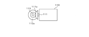
図20は、本発明の第4実施形態を示している。この第4実施形態は、上記第3実施形態の構成において、モータ110の回転軸が入力ギヤ112の回転軸に直交する状態に設置されている。なお、この場合の、入力ギヤ112に噛合する軸受スリーブ122を備えたクラッチ機構120は、2つ備えたものとなっている。
図20は、本発明の第4実施形態を示している。この第4実施形態は、上記第3実施形態の構成において、モータ110の回転軸が入力ギヤ112の回転軸に直交する状態に設置されている。なお、この場合の、入力ギヤ112に噛合する軸受スリーブ122を備えたクラッチ機構120は、2つ備えたものとなっている。
モータ110のモータ軸111の先端には、図21に示すように、かさ歯車を構成する第1ギヤ111aが固定されている。一方、入力ギヤ112の中心にはB方向に延びる入力軸113が固定されており、この入力軸113の先端には、第1ギヤ111aとかさ歯車を構成する第2ギヤ113aが固定されている。そしてこの第2ギヤ113aが、モータ110側の第1のギヤ111aに噛合している。
また、第4実施形態では、出力軸125は各クラッチプレート126には取り付けられてはおらず別体となっている。クラッチプレート126には、出力軸125に代わる軸部126dが同軸的に形成されており、この軸部126dが、軸受スリーブ122の凹所122bに内蔵されている上記コイルばね160に、軸方向に移動自在に挿入されている。軸受スリーブ122には、上記第3実施形態のように出力軸125が貫通する孔は形成されていない。
第4実施形態のクラッチプレート126の外周面には、ギヤ126eが形成されている。出力軸125は、各クラッチプレート126の移動方向(軸部126dの軸方向)と平行な状態で、クラッチプレート126および軸受スリーブ122に並列して回転自在に支持されている。出力軸125の一端部には出力ギヤ125Aが一体に固定されており、この出力ギヤ125Aが、クラッチプレート126の外周面のギヤ126eに噛合している。
この第4実施形態では、モータ110が回転すると、モータ軸111の回転がかさ歯車の第1ギヤ111aから第2ギヤ113aに伝わって入力ギヤ112が回転し、入力ギヤ112に噛合している各軸受スリーブ122が常に回転している状態となる。そして、ダイヤル130が回転し、プッシャ132によってクラッチプレート126がB方向に押されてクラッチ機構120が接続状態になると、軸受スリーブ122の回転がクラッチプレート126に伝わって一体に回転する。そして、回転するクラッチプレート126のギヤ126eに噛合する出力ギヤ125Aが回転し、その出力ギヤ125Aが固定されている出力軸125が回転する。
(4-3)第5実施形態
図22は、本発明の第5実施形態を示している。この第5実施形態は、上記第4実施形態の構成において、図示のようにモータ110を入力ギヤ112とダイヤル130との間にあたる位置に配設するとともに、入力軸113をA方向に延ばし、その入力軸113の先端の第2ギヤ113aに、モータ軸111の第1ギヤ111aを噛合させている。
図22は、本発明の第5実施形態を示している。この第5実施形態は、上記第4実施形態の構成において、図示のようにモータ110を入力ギヤ112とダイヤル130との間にあたる位置に配設するとともに、入力軸113をA方向に延ばし、その入力軸113の先端の第2ギヤ113aに、モータ軸111の第1ギヤ111aを噛合させている。
この第5実施形態では、モータ110が突出して配置されていないことにより図22のA-B方向の寸法が図20の場合よりも小さくなり、コンパクト化が図られ、したがって設計の自由度が高まるといった利点がある。
(4-4)第6実施形態
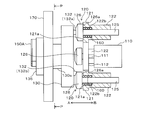
図23は、本発明の第6実施形態を示している。この第6実施形態は、上記第3実施形態の構成において、ダイヤル130(この実施形態では第1のダイヤル130と称する)の回転操作を別のダイヤル(第2のダイヤル:第2の操作部材)135で行ってクラッチ機構120の断接の切り替えを行う構成となっている。
図23は、本発明の第6実施形態を示している。この第6実施形態は、上記第3実施形態の構成において、ダイヤル130(この実施形態では第1のダイヤル130と称する)の回転操作を別のダイヤル(第2のダイヤル:第2の操作部材)135で行ってクラッチ機構120の断接の切り替えを行う構成となっている。
第1のダイヤル130はフレーム170の一面側(図23で右側)に、回転軸130aを介して回転自在に支持されている。そして第2のダイヤル135は、図24に示すように第1のダイヤル130の周囲の同軸ではない位置において、フレーム170の他面側(図23で左側)に回転軸135aを介して回転自在に支持されている。この第2のダイヤル135には、上記スイッチ150と同様のスイッチ150Aが取り付けられている。フレーム170は、上記第2実施形態のように本装置を可動式の車両用シートに適用する場合には、シートフレーム等のフレームとされる。
図24に示すように、第2のダイヤル135の回転軸135aはフレーム170を貫通して一面側に突出しており、この第2のダイヤル135の回転軸135aと第1のダイヤル130の回転軸130aに、伝達ベルト(伝達部材)180が巻回されている。第2のダイヤル135を回転させると、その回転が伝達ベルト180を介して第1のダイヤル130に伝わり、これによって第1のダイヤル130が回転して上記各クラッチ機構120の断接の切り替えが行われる。
この第6実施形態によれば、第1のダイヤル130から離れた任意の位置に第2のダイヤル135を配して各ダイヤル130,135を伝達ベルト180で連結することにより、各クラッチ機構120の断接操作、すなわち駆動させる出力軸125の選択を、クラッチ機構120およびダイヤル130の配設位置に拘束されない位置で行うことができる。したがって設計の自由度が高まる。なお、第2のダイヤル135の回転を第2のダイヤル130に伝える手段としては、伝達ベルト180の他に、1つのギヤ、あるいは複数のギヤが噛み合うギヤ列を採用してもよい。
(4-5)第2実施形態に含まれる他の態様
上記第2実施形態においては、例えば、クラッチ機構120に関しては、摩擦面どうしの接合による摩擦クラッチの代わりに、多数の歯が噛み合う機械式クラッチなどを採用することができる。また、操作部材としてはダイヤル130、135に限られず、レバー等、一端部を回動操作する形式のものであってもよい。
上記第2実施形態においては、例えば、クラッチ機構120に関しては、摩擦面どうしの接合による摩擦クラッチの代わりに、多数の歯が噛み合う機械式クラッチなどを採用することができる。また、操作部材としてはダイヤル130、135に限られず、レバー等、一端部を回動操作する形式のものであってもよい。
また、図18に示したシートの可動部位との連動の構成は一例であり、ダイヤル130の回転によってクラッチ機構120に作用するプッシャ132の数を必要に応じて増減するとともに、ダイヤル130の回転角度とプッシャ132で断接されるクラッチ機構120の配置角度を任意に設定することができる。また、出力軸の数も任意であり、例えばシート座面の高さ調節を、シートクッションの前後2箇所に分けて行う構成とし、これに合わせて出力軸を計4つ具備する構成にも適用可能である。
Claims (12)
- モータ軸を有するモータと、
複数の出力軸と、
これら出力軸ごとに設けられ、出力軸と前記モータ軸とを接続状態とする接続手段と、
これら接続手段のうちの少なくとも1つを前記出力軸に対して選択的に接続させる手動式の操作部材とを備え、
前記操作部材は、一方向にスライドするよう設けられ、
前記接続手段は、該操作部材のスライド方向に沿って配列されていることを特徴とする多軸駆動装置。 - モータ軸を有するモータと、
複数の出力軸と、
これら出力軸ごとに設けられ、出力軸と前記モータ軸とを接続状態とする接続手段と、
これら接続手段のうちの少なくとも1つを前記出力軸に対して選択的に接続させる手動式の操作部材とを備え、
前記操作部材は、任意の回転軸を中心に回転自在に設けられ、
前記接続手段は、該操作部材の回転方向に沿った周方向に沿って配列されていることを特徴とする多軸駆動装置。 - 前記接続手段は、前記モータ軸に係合され、該モータ軸の回転が伝達するシフタ軸と、
このシフタ軸と同心状に配設され、前記出力軸に連結される複数の環状の中間ギヤと、
これら中間ギヤの内周面にそれぞれ突設された中間ギヤ突起とを備え、
前記操作部材は、前記シフタ軸と前記各中間ギヤとを相対的に軸方向に移動させ、シフタ軸を各中間ギヤの内部に挿入させるシフト手段と、
前記シフタ軸の周面に突設され、該シフタ軸が前記中間ギヤの内部に挿入された時に、前記各中間ギヤ突起のうちの少なくとも1つの中間ギヤ突起に対し周方向に係合して、シフタ軸の回転を該中間ギヤに伝達するシフタ突起とを備えることを特徴とする請求項1に記載の多軸駆動装置。 - 前記シフタ突起は前記シフタ軸に複数設けられており、これらシフタ突起の全て、あるいは少なくとも1つが、前記中間ギヤ突起に係合することを特徴とする請求項3に記載の多軸駆動装置。
- 前記シフタ突起と前記中間ギヤ突起の一方あるいは双方に、これらシフタ突起と中間ギヤ突起の軸方向への干渉を回避してシフタ軸の軸方向への移動を促す干渉回避手段が具備されていることを特徴とする請求項3または4に記載の多軸駆動装置。
- 前記シフタ軸が前記中間ギヤの内部に挿入される時に、前記モータを稼働させて前記モータ軸を回転させることにより、前記シフタ突起と前記中間ギヤ突起の軸方向への干渉を回避する制御がなされることを特徴とする請求項3~5のいずれかに記載の多軸駆動装置。
- 前記接続手段は、クラッチ非接続保持部材によって非接続状態とされ、接続状態の時に前記出力軸が回転状態となるクラッチ機構からなり、
前記操作部材は、前記クラッチ機構に対向する状態に配置され、回転運動させられることにより、前記クラッチ機構のうちの少なくとも1つに対応する作用位置に位置付けられ、この作用位置において該クラッチ機構を接続状態とするクラッチ接続部材を有していることを特徴とする請求項2に記載の多軸駆動装置。 - 前記クラッチ接続部材は、前記操作部材に設けられ、該操作部材を回転させることにより前記クラッチ機構の断接がなされ、
前記出力軸には、所定の可動機構が備える可動部位の調節機構が接続され、かつ、前記操作部材には前記モータを作動させるスイッチが設けられており、該スイッチは、前記可動部位の可動方向に適合する箇所に設けられるとともに、該スイッチの操作方向が、前記可動部位の可動方向に適合していることを特徴とする請求項7に記載の多軸駆動装置。 - 前記可動機構が車両用シートであり、該車両用シートが有する可動部位の調節機構に、前記出力軸が接続されていることを特徴とする請求項8に記載の多軸駆動装置。
- 前記クラッチ非接続保持部材は、前記操作部材と連動するカム部材であることを特徴とする請求項7~9のいずれかに記載の多軸駆動装置。
- 前記クラッチ非接続保持部材は弾性部材であることを特徴とする請求項7~9のいずれかに記載の多軸駆動装置。
- 前記操作部材に、伝達部材を介して手動回転式の第2の操作部材を連結し、該第2の操作部材によって前記クラッチ機構の断接操作を行うことを特徴とする請求項7~11のいずれかに記載の多軸駆動装置。
Priority Applications (1)
| Application Number | Priority Date | Filing Date | Title |
|---|---|---|---|
| JP2010547499A JPWO2010084882A1 (ja) | 2009-01-21 | 2010-01-20 | 多軸駆動装置 |
Applications Claiming Priority (6)
| Application Number | Priority Date | Filing Date | Title |
|---|---|---|---|
| JP2009-010921 | 2009-01-21 | ||
| JP2009010921 | 2009-01-21 | ||
| JP2009-048954 | 2009-03-03 | ||
| JP2009048954 | 2009-03-03 | ||
| JP2009115163 | 2009-05-12 | ||
| JP2009-115163 | 2009-05-12 |
Publications (1)
| Publication Number | Publication Date |
|---|---|
| WO2010084882A1 true WO2010084882A1 (ja) | 2010-07-29 |
Family
ID=42355934
Family Applications (1)
| Application Number | Title | Priority Date | Filing Date |
|---|---|---|---|
| PCT/JP2010/050636 Ceased WO2010084882A1 (ja) | 2009-01-21 | 2010-01-20 | 多軸駆動装置 |
Country Status (2)
| Country | Link |
|---|---|
| JP (1) | JPWO2010084882A1 (ja) |
| WO (1) | WO2010084882A1 (ja) |
Cited By (4)
| Publication number | Priority date | Publication date | Assignee | Title |
|---|---|---|---|---|
| WO2012077759A1 (ja) * | 2010-12-08 | 2012-06-14 | 日本発條株式会社 | 出力部材及び多軸駆動装置 |
| JP2016141301A (ja) * | 2015-02-03 | 2016-08-08 | アイシン精機株式会社 | シート駆動装置 |
| CN107848441A (zh) * | 2015-07-01 | 2018-03-27 | 麦格纳座椅公司 | 单马达电动座椅 |
| CN111469733A (zh) * | 2020-04-30 | 2020-07-31 | 长春富晟汽车零部件有限责任公司 | 电动四向头枕机构 |
Citations (2)
| Publication number | Priority date | Publication date | Assignee | Title |
|---|---|---|---|---|
| JPS6428331U (ja) * | 1987-08-12 | 1989-02-20 | ||
| JPH03501832A (ja) * | 1987-10-12 | 1991-04-25 | ハカンソン,ウイリアム | 車輛運転者周りの調節対象物調節装置 |
Family Cites Families (2)
| Publication number | Priority date | Publication date | Assignee | Title |
|---|---|---|---|---|
| JPS63199139A (ja) * | 1987-02-16 | 1988-08-17 | Imasen Denki Seisakusho:Kk | パワ−シ−ト装置の切換クラツチ装置 |
| JPH0645843U (ja) * | 1992-11-30 | 1994-06-21 | デルタ工業株式会社 | リフター |
-
2010
- 2010-01-20 JP JP2010547499A patent/JPWO2010084882A1/ja active Pending
- 2010-01-20 WO PCT/JP2010/050636 patent/WO2010084882A1/ja not_active Ceased
Patent Citations (2)
| Publication number | Priority date | Publication date | Assignee | Title |
|---|---|---|---|---|
| JPS6428331U (ja) * | 1987-08-12 | 1989-02-20 | ||
| JPH03501832A (ja) * | 1987-10-12 | 1991-04-25 | ハカンソン,ウイリアム | 車輛運転者周りの調節対象物調節装置 |
Cited By (12)
| Publication number | Priority date | Publication date | Assignee | Title |
|---|---|---|---|---|
| WO2012077759A1 (ja) * | 2010-12-08 | 2012-06-14 | 日本発條株式会社 | 出力部材及び多軸駆動装置 |
| CN103249964A (zh) * | 2010-12-08 | 2013-08-14 | 日本发条株式会社 | 输出部件以及多轴驱动装置 |
| JP5873806B2 (ja) * | 2010-12-08 | 2016-03-01 | 日本発條株式会社 | 出力部材及び多軸駆動装置 |
| CN103249964B (zh) * | 2010-12-08 | 2016-04-13 | 日本发条株式会社 | 输出部件以及多轴驱动装置 |
| JP2016141301A (ja) * | 2015-02-03 | 2016-08-08 | アイシン精機株式会社 | シート駆動装置 |
| WO2016125410A1 (ja) * | 2015-02-03 | 2016-08-11 | アイシン精機 株式会社 | シート駆動装置 |
| CN107206922A (zh) * | 2015-02-03 | 2017-09-26 | 爱信精机株式会社 | 座椅驱动装置 |
| CN107206922B (zh) * | 2015-02-03 | 2019-07-30 | 爱信精机株式会社 | 座椅驱动装置 |
| US10737591B2 (en) | 2015-02-03 | 2020-08-11 | Aisin Seiki Kabushiki Kaisha | Seat driving device |
| CN107848441A (zh) * | 2015-07-01 | 2018-03-27 | 麦格纳座椅公司 | 单马达电动座椅 |
| CN107848441B (zh) * | 2015-07-01 | 2020-02-28 | 麦格纳座椅公司 | 单马达电动座椅 |
| CN111469733A (zh) * | 2020-04-30 | 2020-07-31 | 长春富晟汽车零部件有限责任公司 | 电动四向头枕机构 |
Also Published As
| Publication number | Publication date |
|---|---|
| JPWO2010084882A1 (ja) | 2012-07-19 |
Similar Documents
| Publication | Publication Date | Title |
|---|---|---|
| US9027442B2 (en) | Multi-shaft drive device | |
| KR101498401B1 (ko) | 동력 전달 기구 및 이것을 이용한 다축 구동 장치 | |
| KR101592076B1 (ko) | 출력 부재 및 다축구동장치 | |
| JP4985744B2 (ja) | シート装置 | |
| JP5797734B2 (ja) | 多軸駆動装置 | |
| EP2180213B1 (en) | Manual transmission | |
| WO2010084882A1 (ja) | 多軸駆動装置 | |
| EP2682640A1 (en) | Multi-shaft drive device | |
| US9388891B2 (en) | Multi-shaft drive device | |
| JP2013160287A (ja) | デファレンシャルギヤ装置 | |
| JPWO2012164646A1 (ja) | 車両用手動変速機の操作機構 | |
| JP2012177459A (ja) | 多軸駆動装置 | |
| US20090293662A1 (en) | Transmission | |
| JP2008232262A (ja) | 変速機の変速操作装置 | |
| CN1900560B (zh) | 变速装置 | |
| JP7779162B2 (ja) | 車両用変速機 | |
| WO2011007791A1 (ja) | クラッチ装置 | |
| EP3249265A1 (en) | Shift fork module | |
| JP2012176734A (ja) | 多軸駆動装置 | |
| EP4481241A1 (en) | Transmission | |
| JP2014047881A (ja) | パーキングロック装置 | |
| KR100802956B1 (ko) | 수동 변속기의 변속 조작장치 | |
| JP2023073841A (ja) | 多軸駆動装置及びパワーシート | |
| JP2012180852A (ja) | 多軸駆動装置 | |
| KR20110099814A (ko) | 다목적 운반차량용 변속장치 |
Legal Events
| Date | Code | Title | Description |
|---|---|---|---|
| 121 | Ep: the epo has been informed by wipo that ep was designated in this application |
Ref document number: 10733489 Country of ref document: EP Kind code of ref document: A1 |
|
| ENP | Entry into the national phase |
Ref document number: 2010547499 Country of ref document: JP Kind code of ref document: A |
|
| NENP | Non-entry into the national phase |
Ref country code: DE |
|
| 122 | Ep: pct application non-entry in european phase |
Ref document number: 10733489 Country of ref document: EP Kind code of ref document: A1 |