WO2010084571A1 - スピーカ装置 - Google Patents
スピーカ装置 Download PDFInfo
- Publication number
- WO2010084571A1 WO2010084571A1 PCT/JP2009/050764 JP2009050764W WO2010084571A1 WO 2010084571 A1 WO2010084571 A1 WO 2010084571A1 JP 2009050764 W JP2009050764 W JP 2009050764W WO 2010084571 A1 WO2010084571 A1 WO 2010084571A1
- Authority
- WO
- WIPO (PCT)
- Prior art keywords
- voice coil
- vibration direction
- speaker device
- diaphragm
- link
- Prior art date
- Legal status (The legal status is an assumption and is not a legal conclusion. Google has not performed a legal analysis and makes no representation as to the accuracy of the status listed.)
- Ceased
Links
Images








Classifications
-
- H—ELECTRICITY
- H04—ELECTRIC COMMUNICATION TECHNIQUE
- H04R—LOUDSPEAKERS, MICROPHONES, GRAMOPHONE PICK-UPS OR LIKE ACOUSTIC ELECTROMECHANICAL TRANSDUCERS; ELECTRIC HEARING AIDS; PUBLIC ADDRESS SYSTEMS
- H04R9/00—Transducers of moving-coil, moving-strip, or moving-wire type
- H04R9/06—Loudspeakers
-
- H—ELECTRICITY
- H04—ELECTRIC COMMUNICATION TECHNIQUE
- H04R—LOUDSPEAKERS, MICROPHONES, GRAMOPHONE PICK-UPS OR LIKE ACOUSTIC ELECTROMECHANICAL TRANSDUCERS; ELECTRIC HEARING AIDS; PUBLIC ADDRESS SYSTEMS
- H04R1/00—Details of transducers, loudspeakers or microphones
- H04R1/42—Combinations of transducers with fluid-pressure or other non-electrical amplifying means
-
- H—ELECTRICITY
- H04—ELECTRIC COMMUNICATION TECHNIQUE
- H04R—LOUDSPEAKERS, MICROPHONES, GRAMOPHONE PICK-UPS OR LIKE ACOUSTIC ELECTROMECHANICAL TRANSDUCERS; ELECTRIC HEARING AIDS; PUBLIC ADDRESS SYSTEMS
- H04R2307/00—Details of diaphragms or cones for electromechanical transducers, their suspension or their manufacture covered by H04R7/00 or H04R31/003, not provided for in any of its subgroups
- H04R2307/021—Diaphragms comprising cellulose-like materials, e.g. wood, paper, linen
-
- H—ELECTRICITY
- H04—ELECTRIC COMMUNICATION TECHNIQUE
- H04R—LOUDSPEAKERS, MICROPHONES, GRAMOPHONE PICK-UPS OR LIKE ACOUSTIC ELECTROMECHANICAL TRANSDUCERS; ELECTRIC HEARING AIDS; PUBLIC ADDRESS SYSTEMS
- H04R2307/00—Details of diaphragms or cones for electromechanical transducers, their suspension or their manufacture covered by H04R7/00 or H04R31/003, not provided for in any of its subgroups
- H04R2307/023—Diaphragms comprising ceramic-like materials, e.g. pure ceramic, glass, boride, nitride, carbide, mica and carbon materials
-
- H—ELECTRICITY
- H04—ELECTRIC COMMUNICATION TECHNIQUE
- H04R—LOUDSPEAKERS, MICROPHONES, GRAMOPHONE PICK-UPS OR LIKE ACOUSTIC ELECTROMECHANICAL TRANSDUCERS; ELECTRIC HEARING AIDS; PUBLIC ADDRESS SYSTEMS
- H04R2307/00—Details of diaphragms or cones for electromechanical transducers, their suspension or their manufacture covered by H04R7/00 or H04R31/003, not provided for in any of its subgroups
- H04R2307/025—Diaphragms comprising polymeric materials
-
- H—ELECTRICITY
- H04—ELECTRIC COMMUNICATION TECHNIQUE
- H04R—LOUDSPEAKERS, MICROPHONES, GRAMOPHONE PICK-UPS OR LIKE ACOUSTIC ELECTROMECHANICAL TRANSDUCERS; ELECTRIC HEARING AIDS; PUBLIC ADDRESS SYSTEMS
- H04R2307/00—Details of diaphragms or cones for electromechanical transducers, their suspension or their manufacture covered by H04R7/00 or H04R31/003, not provided for in any of its subgroups
- H04R2307/027—Diaphragms comprising metallic materials
-
- H—ELECTRICITY
- H04—ELECTRIC COMMUNICATION TECHNIQUE
- H04R—LOUDSPEAKERS, MICROPHONES, GRAMOPHONE PICK-UPS OR LIKE ACOUSTIC ELECTROMECHANICAL TRANSDUCERS; ELECTRIC HEARING AIDS; PUBLIC ADDRESS SYSTEMS
- H04R2307/00—Details of diaphragms or cones for electromechanical transducers, their suspension or their manufacture covered by H04R7/00 or H04R31/003, not provided for in any of its subgroups
- H04R2307/029—Diaphragms comprising fibres
-
- H—ELECTRICITY
- H04—ELECTRIC COMMUNICATION TECHNIQUE
- H04R—LOUDSPEAKERS, MICROPHONES, GRAMOPHONE PICK-UPS OR LIKE ACOUSTIC ELECTROMECHANICAL TRANSDUCERS; ELECTRIC HEARING AIDS; PUBLIC ADDRESS SYSTEMS
- H04R2499/00—Aspects covered by H04R or H04S not otherwise provided for in their subgroups
- H04R2499/10—General applications
- H04R2499/11—Transducers incorporated or for use in hand-held devices, e.g. mobile phones, PDA's, camera's
-
- H—ELECTRICITY
- H04—ELECTRIC COMMUNICATION TECHNIQUE
- H04R—LOUDSPEAKERS, MICROPHONES, GRAMOPHONE PICK-UPS OR LIKE ACOUSTIC ELECTROMECHANICAL TRANSDUCERS; ELECTRIC HEARING AIDS; PUBLIC ADDRESS SYSTEMS
- H04R2499/00—Aspects covered by H04R or H04S not otherwise provided for in their subgroups
- H04R2499/10—General applications
- H04R2499/13—Acoustic transducers and sound field adaptation in vehicles
-
- H—ELECTRICITY
- H04—ELECTRIC COMMUNICATION TECHNIQUE
- H04R—LOUDSPEAKERS, MICROPHONES, GRAMOPHONE PICK-UPS OR LIKE ACOUSTIC ELECTROMECHANICAL TRANSDUCERS; ELECTRIC HEARING AIDS; PUBLIC ADDRESS SYSTEMS
- H04R2499/00—Aspects covered by H04R or H04S not otherwise provided for in their subgroups
- H04R2499/10—General applications
- H04R2499/15—Transducers incorporated in visual displaying devices, e.g. televisions, computer displays, laptops
-
- H—ELECTRICITY
- H04—ELECTRIC COMMUNICATION TECHNIQUE
- H04R—LOUDSPEAKERS, MICROPHONES, GRAMOPHONE PICK-UPS OR LIKE ACOUSTIC ELECTROMECHANICAL TRANSDUCERS; ELECTRIC HEARING AIDS; PUBLIC ADDRESS SYSTEMS
- H04R9/00—Transducers of moving-coil, moving-strip, or moving-wire type
- H04R9/02—Details
- H04R9/04—Construction, mounting, or centering of coil
- H04R9/046—Construction
- H04R9/047—Construction in which the windings of the moving coil lay in the same plane
Definitions
- the present invention relates to a speaker device.
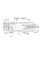
- FIG. 1 is an explanatory view showing a conventional speaker device.
- a dynamic speaker device is known as a general speaker device (see, for example, Patent Document 1). As shown in FIG. 1, for example, this dynamic speaker device is joined to a frame 3J, a cone-shaped diaphragm 21J, an edge 4J that supports the diaphragm 21J on the frame 3J, and an inner peripheral portion of the diaphragm 21J.
- the voice coil bobbin 610J, the damper 7J that supports the voice coil bobbin 610J on the frame 3J, the voice coil 611J wound around the voice coil bobbin 610J, the yoke portion 51J, the magnet 52J, and the plate 53J, and the voice coil 611J are arranged.
- a magnetic circuit having a magnetic gap formed thereon In this speaker device, when a voice signal is input to the voice coil 611J, the voice coil bobbin 610J vibrates due to the Lorentz force generated in the voice coil 611J in the magnetic gap, and the diaphragm 21J is driven by the vibration.
- the general dynamic speaker device described above has a voice coil 611J disposed on the side opposite to the acoustic radiation side of the diaphragm 21J, and vibration directions of the voice coil 611J and the voice coil bobbin 610J. And the vibration direction of the diaphragm 21J is the same.
- the region for vibrating the diaphragm 21J, the region for vibrating the voice coil bobbin 610J, the region where the magnetic circuit is disposed, and the like are in the vibration direction (acoustic radiation direction) of the diaphragm 21J. Therefore, the overall height of the speaker device must be relatively large.
- the size of the diaphragm 21J of the speaker device along the vibration direction is the same as the size of the cone-shaped diaphragm 21J along the vibration direction and the diaphragm 21J is supported by the frame 3J.
- the height of the edge 4J (a), the voice coil bobbin height (b) from the joint between the diaphragm 21J and the voice coil bobbin 610J to the upper end of the voice coil 611J, the voice coil height (c), and the main magnet of the magnetic circuit It consists of the height (d), the thickness (e) of the yoke portion 51J of the magnetic circuit, and the like.
- the vibration direction of the voice coil bobbin 610J and the vibration direction of the diaphragm 21J are the same direction, if the amplitude of the diaphragm 21J is increased to obtain a large volume, In order to ensure the vibration stroke of the voice coil bobbin 610J, the overall height of the speaker device becomes large, and it is difficult to achieve thinning of the device. That is, there is a problem that it is difficult to achieve both a reduction in device thickness and an increase in volume.
- the vibration of the voice coil 611J is directly transmitted to the diaphragm 21J, that is, the vibration direction of the voice coil 611J and the vibration direction of the diaphragm 21J.
- the vibration direction of the voice coil 611J and the vibration direction of the diaphragm 21J are different, the vibration of the voice coil 611J may not be reliably transmitted to the diaphragm 21J, which causes a problem that the reproduction efficiency of the speaker device is deteriorated. Arise.
- the voice coil bobbin 610J is joined to the inner periphery of the cone-shaped diaphragm 21J, and the driving force is transmitted from the voice coil bobbin 610J to the inner periphery of the diaphragm 21J. It is relatively difficult to drive the entire diaphragm at substantially the same phase. Therefore, a speaker device that can drive the entire diaphragm with substantially the same phase is desired.
- a capacitor type speaker device is known as a thin speaker device.
- This capacitor type speaker device has a structure in which a diaphragm (movable electrode) and a fixed electrode are arranged facing each other.
- the diaphragm is displaced by applying a DC voltage between the electrodes, and when a signal on which an audio signal is superimposed is input to the electrodes, the diaphragm vibrates according to the signal.
- the driving force may change significantly in a non-linear manner, and the sound quality of the reproduced sound may be relatively low.
- the present invention is an example of a problem to deal with such a problem. That is, to provide a thin speaker device that can radiate a large volume of reproduced sound with a relatively simple structure, to reliably transmit the vibration of the voice coil to the diaphragm, and to obtain a speaker device with high reproduction efficiency, Provided is a thin speaker device capable of emitting high-quality reproduced sound with a relatively simple structure, and also provides a thin speaker device in which a diaphragm vibrates in substantially the same phase with a relatively simple configuration. This is the object of the present invention.
- the speaker device includes at least the configuration according to the following independent claims.
- [Claim 1] A diaphragm, a stationary part that supports the diaphragm so as to vibrate freely along a vibration direction, and a drive part that is provided in the stationary part and that vibrates the diaphragm by an audio signal,
- the drive unit includes a magnetic circuit that forms a magnetic gap along a direction different from a vibration direction of the diaphragm, a voice coil supported in the magnetic gap, and a direction change of vibration of the voice coil to change the direction of the vibration.
- a rigid vibration direction converting portion to be transmitted to the diaphragm, and positions of both end portions between the voice coil side end of the vibration direction converting portion and the end of the voice coil on the vibration direction converting portion side.
- a speaker device comprising a connecting portion for connecting differently along the vibration direction.
- a speaker device is provided with a diaphragm, a stationary part that supports the diaphragm so as to freely vibrate along a vibration direction, and provides vibration to the diaphragm by an audio signal.
- a drive unit wherein the drive unit forms a magnetic gap along a direction different from the vibration direction of the diaphragm, a voice coil supported in the magnetic gap, and vibration of the voice coil
- a rigid vibration direction conversion portion that changes the direction of the vibration and transmits the same to the diaphragm, and between the end on the voice coil side of the vibration direction conversion portion and the end on the vibration direction conversion portion side of the voice coil. Further, it is characterized in that a connecting portion is provided for connecting the both end portions with different positions along the vibration direction.
- the position of the end of the voice coil on the vibration direction conversion unit side is positioned closer to the position of the voice coil side end of the vibration direction conversion unit than the diaphragm.
- the connecting portion has rigidity. Since the connecting portion has rigidity, the voice coil and the vibration direction changing portion can be connected without deformation, and the vibration of the voice coil can be reliably changed in direction and transmitted to the diaphragm. Further, the length of the connecting portion from the upper end portion to the lower end portion is larger than the thickness of the voice coil. When the thickness of the voice coil is within the thickness of the connecting portion, the thickness of the connecting portion where the peripheral member contacts the voice coil can be eliminated.
- the connecting portion extends along the width direction of the voice coil.
- the connecting portion has a through hole penetrating along a vibration direction of the voice coil.
- the vibration direction conversion unit functions to change the direction of the vibration of the voice coil and transmit it to the diaphragm.
- the diaphragm vibrates along a vibration direction different from the voice coil (for example, orthogonal to the voice coil) by the driving force transmitted through the vibration direction conversion unit.
- a voice coil bobbin is disposed on the back side of the diaphragm, and the vibration direction of the diaphragm and the vibration direction of the voice coil bobbin are configured in the same direction. Since the diaphragm and the voice coil bobbin require a region for vibration, the width (overall height) along the acoustic radiation direction of the speaker device is relatively large.
- a magnetic circuit that forms a magnetic gap formed in a direction different from the vibration direction of the diaphragm, preferably in a direction orthogonal to the vibration direction of the diaphragm.
- a voice coil that vibrates along its magnetic circuit, and also has a rigid vibration direction converter that changes the direction of vibration of the voice coil and transmits it to the diaphragm.
- the width along the radial direction is relatively small. That is, a thin speaker device can be provided.
- the vibration stroke of the voice coil can be set in a direction that does not affect the overall height of the speaker device, it is easy to achieve a thin speaker device even when the vibration stroke of the voice coil, that is, the amplitude of the diaphragm is increased. This makes it possible to achieve both a reduction in the thickness of the speaker device and an increase in volume.
- the positions of both ends are set between the end on the voice coil side of the vibration direction conversion unit and the end on the vibration direction conversion unit side of the voice coil. Since the connecting part is connected to the vibration direction changing part, a part of the height of the magnetic circuit for vibrating the voice coil can be overlapped with the height of the vibration direction changing part. It is possible to further reduce the thickness of the speaker device along the direction.
- the position of the end portion of the voice coil on the vibration direction converting portion side is located closer to the voice coil side in the vibration direction converting portion than the diaphragm, the connection with the voice coil is restricted. Therefore, the height of the vibration direction changing portion can be secured without any change, and the vibration of the voice coil can be greatly converted and transmitted to the diaphragm.
- the connecting portion By extending the connecting portion along the width direction of the voice coil, the voice coil and the vibration direction converting portion can be reliably connected, and the connecting portion reinforces the strength in the width direction of the voice coil. can do.
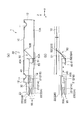
- FIGS. 2 to 4 are explanatory views showing the overall configuration of the speaker device according to the embodiment of the present invention (FIG. 2A is a cross-sectional view along the X-axis direction, and FIG. 2B is a drive unit). Explanatory drawing which showed operation
- the speaker devices 1, 1 ⁇ / b> A, and 1 ⁇ / b> B are provided with a diaphragm 10, a frame 12 that supports the diaphragm 10 so as to freely vibrate along a vibration direction, and a drive unit that is provided on the frame 12 and that vibrates the diaphragm 10 with an audio signal
- the drive unit 14 includes a magnetic circuit 20 that forms a magnetic gap 20G along a direction different from the vibration direction of the diaphragm 10, and a voice coil 30 that is supported in the magnetic gap 20G.
- a voice coil support unit 40 that can vibrate along 20G, and a rigid vibration direction conversion unit 50 that changes the direction of vibration of the voice coil support unit 40 and transmits the vibration to the diaphragm 10.
- the vibration direction of the voice coil support section 40 is defined as the X-axis direction, and the two directions orthogonal thereto are defined as the Y-axis direction and the Z-axis direction, respectively.
- the voice coil 30 is supported by the voice coil support portion 40.
- the present invention is not limited to this, and the voice coil 30 itself may vibrate so as to have rigidity.
- the diaphragm 10 is supported by the frame 12 so as to vibrate along the vibration direction (Z-axis direction) as shown in the figure.
- the diaphragm 10 emits sound waves in the acoustic radiation direction when the speaker is driven.
- the diaphragm 10 is supported by the frame 12 through the edge 11, and movement along the direction other than the vibration direction, specifically, the X-axis direction and the Y-axis direction is restricted by the edge 11.
- the edge 11 and the diaphragm 10 may be integrally formed.
- a portion that does not vibrate actively due to the vibration of the voice coil 30 is a stationary portion. Therefore, the constituent members of the frame 12 and the magnetic circuit 20 become a stationary part, and the diaphragm 10 is supported so as to be able to vibrate with respect to the stationary part.
- the material for forming the diaphragm 10 for example, a resin material, a metal material, a paper material, a ceramic material, a composite material, or the like can be employed.
- the diaphragm 10 preferably has rigidity, for example.
- the diaphragm 10 can be formed in a defined shape such as a flat plate shape, a dome shape, or a cone shape.
- the diaphragm 10 is formed in a flat plate shape, and is supported along the planar bottom surface 12 ⁇ / b> A of the frame 12.
- a flat diaphragm 10 is particularly preferable.
- the diaphragm 10 can be formed in a specified shape such as a rectangular shape, an elliptical shape, a circular shape, or a polygonal shape as viewed from the acoustic radiation direction (planar shape).
- a protrusion may be formed on the front surface (surface on the acoustic radiation side) or the back surface (surface opposite to the acoustic radiation side) of the diaphragm 10.
- the protrusion has a function of increasing the rigidity of the diaphragm 10.
- the protrusions may be formed in a linear shape, a ring shape, or a lattice shape with respect to the surface of the diaphragm 10.
- a plurality of linear protrusion portions may be formed on the surface of the diaphragm.
- the diaphragm 10 is supported by the frame 12 so as to freely vibrate, and a space surrounded by the diaphragm 10 and the frame 12 on the back side (the opposite side to the acoustic radiation direction) of the diaphragm 10 is relative to the acoustic radiation direction. In the case where it is blocked, it is possible to prevent sound waves emitted from the back side of the diaphragm 10 from being emitted toward the acoustic radiation direction.
- the edge 11 is disposed between the diaphragm 10 and the frame 12, and the inner peripheral portion supports the outer peripheral portion of the diaphragm 10 and the outer peripheral portion is joined to the frame 12. Hold. Specifically, the edge 11 supports the diaphragm 10 so that it can vibrate along the vibration direction (Z-axis direction) and brakes in a direction orthogonal to the vibration direction.
- the illustrated edge 11 is formed in a ring shape (annular) when viewed from the acoustic radiation direction, and the cross-sectional shape is formed in a prescribed shape, for example, a convex shape, a concave shape, a corrugated shape, or the like.
- the illustrated edge 11 is formed in a concave shape in the acoustic radiation direction, but may be formed in a convex shape in the acoustic radiation direction.
- the edge 11 can employ, for example, leather, cloth, rubber, resin, a material obtained by applying a sealing process thereto, a member obtained by molding rubber, resin, or the like into a predetermined shape.
- the drive unit 14 includes a magnetic circuit 20, a voice coil support unit 40, and a vibration direction conversion unit 50.
- the magnetic circuit 20 forms a magnetic gap 20G along a direction (for example, the X-axis direction) different from the vibration direction (for example, the Z-axis direction) of the diaphragm 10.
- the magnetic gap 20G is formed along the direction orthogonal to the vibration direction of the diaphragm 10, but the invention is not particularly limited thereto.
- the voice coil support unit 40 has a voice coil 30 supported in the magnetic gap 20G and vibrates along the magnetic gap 20G. The movement of the voice coil support unit 40 is restricted by a holding unit, which will be described later, and is allowed to move only in the direction along the magnetic gap 20G.
- the voice coil support unit 40 When the voice signal SS is input to the voice coil 30, the voice coil support unit 40 is moved into the magnetic gap 20G. A Lorentz force along the X-axis direction acts on the voice coil 30, and the voice coil support portion 40 integrated with the voice coil 30 vibrates along the X-axis direction.
- the frame 12 supports the vibration plate 10 so as to freely vibrate along the vibration direction and supports the driving unit 14 inside. Further, the frame 12 supports a part of a link mechanism of a vibration direction conversion unit 50 described later, and applies a reaction force from the frame 12 to the operation of the link mechanism.
- a frame 12 preferably has a planar bottom surface 12A.
- the frame 12 is also a stationary part that is stationary with respect to the operation of the voice coil 30 as described above.
- the stationary portion refers to a portion that does not vibrate actively due to vibration of the voice coil 30, and does not necessarily mean a completely stationary state. Therefore, for example, it is only necessary to be stationary to the extent that the diaphragm 10 can be supported, and vibration generated when driving the speaker devices 1, 1 ⁇ / b> A, 1 ⁇ / b> B may be propagated and generated in the entire stationary portion. Absent.
- the stationary portion is not only a part of the frame 12 and the magnetic circuit 20 but also the mounting position where the speaker devices 1, 1 ⁇ / b> A, 1 ⁇ / b> B are mounted, and the magnetic circuit 20. Applicable members and the like are applicable.
- the vibration direction converter 50 changes the direction of the vibration of the voice coil 30 and transmits it to the diaphragm 10.
- the vibration direction conversion unit 50 includes a rigid link portion 51, and changes the direction of the vibration of the voice coil 30 by changing the angle of the link portion 51 formed between the voice coil 30 and the diaphragm 10. And transmitted to the diaphragm 10.
- the voice coil 30 and the vibration direction conversion unit 50 are connected via a connection unit 60.
- the voice coil support part 40 is connected to the vibration direction changing part 50 via the connecting part 60, but when the voice coil 30 itself is a rigid structure, the voice coil 30 is directly connected to the connecting part.
- the connecting portion 60 is formed between the end portion 50A on the voice coil support portion side in the vibration direction conversion portion 50 and the end portion 40A on the vibration direction conversion portion side of the voice coil support portion 40, and positions of both ends are determined in the vibration direction. Are differently connected along the line.
- the position of the end of the voice coil 30 on the vibration direction conversion unit 50 side is positioned by the connecting portion 60 relative to the position of the end of the vibration direction conversion unit 50 on the voice coil 30 side from the diaphragm. ing.
- the arrangement of the voice coil support part 40 (arrangement of the voice coil 30) can be shifted in the height direction of the vibration direction conversion part 50, and the height of the magnetic circuit 20 is changed to the height of the vibration direction conversion part 50.
- the total height can be further reduced.
- the height of the vibration direction converter 50 can be sufficiently secured, so that the vibration of the voice coil 30 can be converted into the vibration of the diaphragm 10 with a large amplitude.
- the vibration direction converter 50 is formed by one link portion 51, and the end 50 ⁇ / b> A on the voice coil support portion 40 side of the vibration direction converter 50 is a link portion.
- 51 is formed by a joint portion 52 (52A) that connects the link portion 51 to the diaphragm 10
- the end portion 50B on the diaphragm 10 side of the vibration direction converting portion 50 is connected by the joint portion 52 (52B) that connects the link portion 51 to the diaphragm 10. Is formed.
- the joint portion 52 rotatably connects the link portion 51 and the connection target, and one end of the vibration direction conversion portion 50 is connected to the voice coil 30 side so that the angle can be changed by the joint portion 52A, and the other end is connected.
- a link mechanism is provided which is connected to the diaphragm 10 side by joint portions 52B so as to be changeable, and includes link portions 51 which are obliquely arranged with respect to the vibration direction of the voice coil 30 and the vibration direction of the diaphragm 10, respectively. .
- the joint portion 52A on the voice coil 30 side moves in the X-axis direction along with the movement of the voice coil support portion 40, and on the diaphragm 10 side.
- the joint portion 52B moves along the vibration direction of the diaphragm 10 (for example, the Z-axis direction).
- the vibration direction conversion unit 50 is formed by a link mechanism 50L including a rigid first link portion 51A and a second link portion 51B.
- An end portion 50A on the voice coil support portion 40 side of the vibration direction conversion portion 50 is formed by a joint portion 52A that connects the first link portion 51A to the connection portion 60, and an end portion on the diaphragm 10 side of the vibration direction conversion portion 50 50B is formed by a joint portion 52B that connects the first link portion 51A to the diaphragm 10.
- the first link portion 51A and the second link portion 51B are inclined in different directions with respect to the vibration direction of the voice coil support portion 40, and one end of the second link portion 51B is in the middle of the first link portion 51A.
- the other end of the second link portion 51B is connected to the bottom portion 12A of the frame 12 serving as the stationary portion 13 by the joint portion 52D.
- the stationary part 13 is provided on the side opposite to the diaphragm 10 side with respect to the vibration direction converting part 50.
- the joint portions 52A, 52B, 52C, and 52D connect the first link portion 51A, the second link portion 51B, and the connection target in a freely rotatable manner, and the voice coil
- the joint portion 52A on the support portion 40 side moves in the X-axis direction along with the movement of the voice coil support portion 40, and the joint portion 52D connected to the stationary portion 13 is in a fixed state and receives from the stationary portion 13. Due to the force, the movement of the joint portion 52A is converted into an angle change between the first link portion 51A and the second link portion 51B, and the vibration direction of the vibration plate 10 (for example, the Z-axis direction) Move to.
- the speaker device 1B includes the drive units 14 shown in FIG. 3 arranged symmetrically facing each other, and includes drive units 14 (R) and 14 (L).
- Link mechanisms 50L (R), 50L (L), voice coil support sections 40 (R), 40 (L), and magnetic circuits 20 (R), 20 (L), drive mechanisms 14 (R), 14 (L) Connecting portions 60 (R) and 60 (L) are provided.
- the two drive units 14 (R), 40 (R), 40 (L) are reversed by synchronizing the vibration directions of the voice coil support units 40 (R), 40 (L).
- the diaphragm 10 can be vibrated by combining the driving force of 14 (L).
- the joint portion 52B on the diaphragm 10 side can be provided at a plurality of locations, the support points of the diaphragm 10 are increased, the phases of vibrations of the diaphragm 10 are matched, and the diaphragm 10 is vibrated at substantially the same phase. Is possible.
- the voice coil support portions 40 (R) and 40 (L) vibrate in the horizontal direction, for example, facing each other, the horizontal vibrations cancel each other. It is possible to deter transmission.
- the voice coil support portion 40 vibrates along 20G, and the vibration is changed in direction by the vibration direction changing portion 50 and transmitted to the vibration plate 10, thereby vibrating the vibration plate 10 to emit sound.
- a sound corresponding to the audio signal SS is emitted in the direction SD.
- the driving force of the magnetic circuit 20 or the vibration stroke of the voice coil support portion 40 is changed.
- Increasing the size does not directly affect the size of the speaker devices 1, 1A, 1B in the thickness direction (Z-axis direction). Therefore, it is possible to reduce the thickness of the speaker devices 1, 1A, 1B while increasing the volume.
- the vibration direction conversion unit 50 converts the vibration direction of the voice coil support unit 40 and transmits it to the diaphragm 10 by a mechanical link mechanism, the vibration transmission efficiency is high.
- the angle change between the first link portion 51A and the second link portion 51B is caused by the vibration of the voice coil support portion 40 and the stationary portion 13. Therefore, the vibration from the voice coil support portion 40 can be transmitted to the diaphragm 10 more reliably. Thereby, good reproduction efficiency of the speaker devices 1A and 1B can be obtained.
- connection part 60 a level
- FIG. As a result, the width (height) of the magnetic circuit 20 in the Z-axis direction can be accommodated within the height of the vibration direction converter 50, and the height of the magnetic circuit 20 required for securing the driving force can be reduced. It is possible to reduce the thickness of the speaker devices 1 to 1B while ensuring sufficient. Further, by providing the connecting portion 60, the required height of the vibration direction changing portion 50 (the length of the link portion 51) can be sufficiently ensured even if the speaker devices 1 to 1B are thinned. Ten large amplitudes can be obtained.
- the bottom surface 61 of the connecting portion 60 so as to slide along the bottom surface 12A of the frame 12 or the stationary portion 13, it becomes possible to stabilize the vibration of the voice coil support portion 40, and The movement of the end 50A of the vibration direction converter 50 can be performed linearly, and the movement of the end 50B of the vibration direction converter 50 connected to the diaphragm 10 can be reliably and stabilized.
- the voice coil 30 can be smoothly vibrated and the generation of abnormal noise when driving the speaker device is suppressed. Can do.
- FIG. 5 is an explanatory view for explaining the voice coil support portion, the connecting portion, the holding portion, and the mounting unit
- FIG. 5A is a perspective view seen from the middle direction between the X-axis direction and the Y-axis direction, and FIG. It is the perspective view seen from the reverse direction).
- FIG. 5A is a perspective view seen from the middle direction between the X-axis direction and the Y-axis direction, and FIG. It is the perspective view seen from the reverse direction.
- the voice coil support portion 40 has a connection portion 60 attached to one end in the vibration direction, and the connection portion 60 is attached so as to extend along the width of the voice coil support portion 40.
- a voice coil attachment location 41a is formed on a flat insulating flat plate 41, and the voice coil 30 is attached to the voice coil attachment location 41a.
- An opening 41b is formed on the inner side of the voice coil 30 in the voice coil support portion 40 to reduce the weight of the voice coil support portion 40.
- the material constituting the voice coil support portion 40 resin materials (including adhesive resins, curable resins, etc.), metal materials, ceramic materials, composite materials, and the like can be adopted. If it is a material which gives rigidity to such an extent that does not change, it will not be specifically limited. As described above, in the illustrated description, the example in which the connecting portion 60 is connected to the voice coil support portion 40 is shown. However, the present invention is not limited to this, and the voice coil support is provided as long as the voice coil 30 itself has rigidity. Since the part 40 becomes unnecessary, the connecting part 60 may be directly connected to the voice coil 30. In this case, it is preferable to appropriately treat the voice coil 30 such that the connecting portion 60 or the vibration direction changing portion 50 is electrically insulated.
- connection portion 60 is formed with a connection hole 60 s to which an end portion 50 ⁇ / b> A (a connection portion 53 described later) of the vibration direction conversion portion 50 is connected, and a through hole penetrating along the vibration direction of the voice coil support portion 40. 60p is formed.
- the through hole 60p is a vent hole formed in order to prevent the connecting portion 60 from becoming resistance (acoustic mechanical resistance) against vibration of the voice coil support portion 40.
- the voice coil support part 40 and the connecting part 60 are held by the frame 12 by the holding part 15 directly or via other members.
- the holding unit 15 includes a structure for restricting movement of the voice coil support unit 40 in other directions while allowing movement of the voice coil support unit 40 along the X-axis direction. Specifically, the holding unit 15 extends along the Z-axis direction.
- a convex curve along the X-axis direction is formed by a plate material having a certain thickness, and other deformations are restricted while allowing deformation in the bending and extending direction of the curve.
- One end of the holding portion 15 is connected to the voice coil support portion 40 or the connecting portion 60 and the other end is connected to the mounting unit 16, or an intermediate portion thereof is connected to the voice coil support portion 40 or the connecting portion 60.
- the both ends are connected to the mounting unit 16.
- the voice coil support portion 40 or the connecting portion 60 is held by the frame 12 via the mounting unit 16, but the present invention is not limited thereto, and the end portion of the holding portion 15 may be directly connected to the frame 12.
- the holding unit 15 includes a first holding unit 15 ⁇ / b> A and a second holding unit 15 ⁇ / b> B, and the first holding unit 15 ⁇ / b> A and the second holding unit 15 ⁇ / b> B are voiced via the mounting unit 16.
- the coil support 40 is held on the frame 12.
- the outer ends of the first holding portions 15A are connected to the mounting unit 16, respectively.
- engagement protrusions 60a and 60a are formed at both outer end portions of the connecting portion 60, and the inner end portion of the first holding portion 15A is engaged with the engagement protrusions 60a and 60a.
- Engaging holes 15a, 15a are formed.
- the attachment unit 16 is formed with first connection portions 16a and 16a on both the left and right sides of the connecting portion 60, and the outer end of the first holding portion 15A has first connection portions 16a and 16a.
- An engagement hole 15a that engages with the engagement protrusions 16a1 and 16a1 is formed.
- the second holding portion 15B has a central portion of one member connected to the second connecting portion 16b of the mounting unit 16, and both ends thereof connected to the left and right ends of the voice coil support portion 40.
- An engagement protrusion 16b1 is formed on the second connection portion 16b, and the engagement hole 15b of the second holding portion 15B is engaged with the engagement protrusion 16b1.
- Engagement protrusions 41c and 41c are formed on the left and right ends of the voice coil support part 40, and engagement holes 15b formed at both ends of the second holding part 15B are engaged with the engagement protrusions 41c and 41c. .
- the second holding portion 15B is disposed within the width of the voice coil support portion 40 so that the holding mechanism of the voice coil support portion 40 is not bulky in the width direction of the voice coil support portion 40.
- the second connection portion 16b is arranged on both the left and right sides in the same manner as the first connection portion 16a, and the left and right ends of the voice coil support portion 40 are respectively connected to the second holding portion 15B.
- the right and left second connection portions 16b may be connected.
- the attachment unit 16 includes a first connection portion 16a to which the end portion of the first holding portion 15A is connected on both the left and right sides of the connecting portion 60, and a second connection portion to which the second holding portion 15B is connected.
- 16b is provided behind the voice coil support portion 40, and has an integrated support portion 16c that integrally supports the first connection portion 16a and the second connection portion 16b.
- it has the attachment latching
- the first connection portion 16a of the attachment unit 16 is also used as an audio signal input terminal, and an audio signal is supplied to the voice coil 30 via the first holding portion 15A. can do.
- the signal line is placed along the first holding portion 15A
- the first holding portion 15A is a flexible wiring board, or the first holding portion 15A is formed of a conductive material and is itself Can be either a signal line.
- the voice coil lead wire 43 from the voice coil 30 is formed on the insulating flat plate 41, the tip of the voice coil lead wire 43 is electrically connected to the voice coil connection terminal 42, and the voice coil connection terminal 42 is 1 is electrically connected to the signal line terminal of the holding portion 15A.
- the voice coil is connected to the first holding part 15A. There is no need to electrically connect the connection terminal 42 and the first connection portion 16a which is an audio signal input terminal.
- the wiring space of the input signal line can be saved, and the space efficiency in the apparatus can be increased. Further, the signal line does not fluctuate even when the voice coil support part 40 vibrates, and there is no problem that the signal line comes into contact with each part in the apparatus and generates abnormal noise.
- the magnetic circuit 20 for vibrating the voice coil support unit 40 not only forms a magnetic gap 20G along the vibration direction of the voice coil support unit 40, but is also wound in a plane on the voice coil support unit 40.
- the magnetic gap 20G forms a pair of magnetic fields in opposite directions.
- the magnetic circuit 20 is formed by a magnet 21 (21A, 21B) and a yoke portion 22 (22A, 22B), and has a pair of magnetic poles opposite to each other in the Z-axis direction.
- the magnets 21A and 21B are arranged at predetermined intervals in the X-axis direction, and the above-described magnetic gap 20G is formed between the pair of magnets 21A and 21B and the yoke portion 22B.
- the voice coil 30 is wound so that the currents flowing on the magnets 21A and 21B are opposite to each other in the Y-axis direction, so that the Lorentz force along the X-axis direction acts on the voice coil 30.
- the magnetic circuit 20 having the same function as described above can be formed.
- the magnetic circuit 20 has a plurality of magnets 21 (21A to 21D).
- the magnets 21 are provided on both sides along the direction of the magnetic field of the magnetic gap 20G.
- the yoke portion 22 includes a lower yoke portion 22A, an upper yoke portion 22B, and a column portion 22C.
- the yoke portions 22A and 22B are disposed substantially parallel to each other with a specified interval, and the column portion 22C is formed at the center portion so as to extend in a direction substantially orthogonal to the yoke portions 22A and 22B. .
- Magnets 21A to 21D are arranged in the yoke portions 22A and 22B, and one magnetic gap 20G2 is formed by the magnet 21A and the magnet 21C, and another magnetic gap 20G1 is formed by the magnet 21B and the magnet 21D.
- the pair of magnetic gaps 20G1 and 20G2 are formed side by side in a plane, and magnetic fields in opposite directions are formed.
- the voice coil 30 is formed in a substantially rectangular planar shape, and includes linear portions 30A and 30C formed along the Y-axis direction and linear portions 30B and 30D formed along the X-axis direction. It is configured.
- the straight portions 30A and 30C of the voice coil 30 are arranged in the magnetic gap 20G of the magnetic circuit 20, and are defined so that the direction of the magnetic field is along the Z-axis direction. It is preferable not to apply a magnetic field to the straight portions 30B and 30D of the voice coil 30. Further, even when a magnetic field is applied to the straight portions 30B and 30D, the Lorentz forces generated in the straight portions 30B and 30D are configured to cancel each other.
- the voice coil 30 can have a relatively large portion in the magnetic gap 20G by relatively increasing the number of turns, and can obtain a relatively large driving force when the speaker is driven.
- the magnetic circuit 20 includes a plurality of magnets 21A to 21D such that the direction of the magnetic field applied to the linear portion 30A of the voice coil 30 is opposite to the direction of the magnetic field related to the linear portion 30C.
- the magnet 21A and the magnet 21C are magnetized in the same direction, and the magnet 21B and the magnet 21D are magnetized in the opposite direction. Magnetization of the magnet 21 can be performed after the magnet 21 and the yoke portion 22 are assembled. In the examples shown in FIGS. 2 to 4 and FIGS. 6 and 7, the magnetization process at that time is performed twice. Is required.
- the magnetic gap 20G2 is formed by magnets 21A and 21C magnetized in the same direction, and the magnetic gap 20G1 is formed on the yoke protrusions 22a and 22B formed on the yoke portions 22A and 22B, respectively. It is formed between 22b. According to this, the magnetizing process performed after assembling the magnet 21 and the yoke part 22 can be completed once, and the process can be simplified.
- a link mechanism 50L is formed by the first link portion 51A, the second link portion 51B, and the joint portions 52A, 52B, 52C, and 52D.
- the joint portion 52D between the second link portion 51B and the stationary portion 13 is a joint portion where the position is not displaced, and the other joint portions 52A, 52B, 52C are joint portions whose positions are displaced.
- the entire link mechanism 50L is structured to receive the reaction force from the stationary portion 13 at the joint portion 52D.
- the vibration direction converter 50 can be formed by a plate-like member having a linear refracting portion, and this refracting portion can be used as the joint portion of the link mechanism 50L described above. That is, in the illustrated example, the first link portion 51A and the second link portion 51B are formed by plate members, and the joint portions 52A, 52B, 52C, and 52D of the link mechanism 50L are formed by linear refracting portions. be able to. According to this, since the joining portion with the diaphragm 10 can be joined linearly, the planar diaphragm 10 can be vibrated uniformly along the width direction, and the entire diaphragm is substantially omitted. It is possible to vibrate with the same phase.
- each link portion has rigidity, vibrations in the natural vibration mode are less likely to occur, the flexural vibration of the link portion is prevented from adversely affecting the vibration of the diaphragm 10, and the acoustic characteristics are reduced. Can be suppressed.
- a vent hole may be formed.
- the vent hole can reduce local fluctuations in the air pressure in the space surrounded by the diaphragm 10 and the frame 12 when the speaker vibrates, and suppresses braking of the vibration direction converter 50 due to the air pressure.
- a hollow portion is formed in the link portion by the vent hole, and the link portion can be reduced in weight, thereby enabling high-frequency reproduction.
- the weight reduction of the vibration direction converter is particularly effective for widening the reproduction characteristics and increasing the amplitude and sound pressure level of the sound wave for a predetermined audio current.
- the vibration direction conversion unit 50 may be made of an integral part connected by a refracting unit.
- the vibration direction changing part 50 forming a complicated link mechanism can be immediately joined to the voice coil support part 40 and the diaphragm 10, and the assemblability of the apparatus is improved.
- the vibration direction conversion part 50 can also be formed integrally with the voice coil 30 (including the voice coil support part 40) and the diaphragm 10, for example.
- the joint portions 52A, 52B, 52C, and 52D may be constituted by mechanically-jointed joints, members made of fibers made of a polymer such as polyester or polyaramid, polyurethane resin, or rubber. Etc., or a flexible member such as a flexible film.
- the voice coil 30 and the vibration direction conversion unit 50 are integrally formed of a prescribed material such as a resin material, and are processed so as to be bent at a predetermined position, thereby performing joint processing 52A, 52B, 52C, 52D. May be formed.
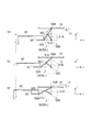
- FIG. 9 is an explanatory diagram for explaining the operation of the vibration direction converter 50 in the embodiment of the present invention. More specifically, FIG. 9B shows the state of the vibration direction converter 50 with the diaphragm 10 positioned at the reference position, and FIG. 9A shows the state where the diaphragm 10 is displaced toward the acoustic radiation side with respect to the reference position. FIG. 9C shows the state of the vibration direction conversion unit 50 in a state where the vibration plate 10 is displaced in the opposite direction with respect to the acoustic radiation side with respect to the reference position. Show.
- the joint portion 52D is the only joint portion whose position does not fluctuate and is supported by the stationary portion 13 (or the frame 12), and applies a reaction force from the stationary portion 13 to the link mechanism 50L.
- the voice coil support section 40 moves from the reference position X0 by X1 in the X-axis direction, as shown in FIG. 9A, the first link portion 51A and the second link portion 51A inclined in different directions are arranged.
- the angle of the link portion 51B rises almost the same angle, and the joint portion 52B reliably pushes up the diaphragm 10 from the reference position Z0 in the Z-axis direction by Z1 in response to the reaction force from the stationary portion 13 at the joint portion 52D.
- the angle between the first link portion 51A and the second link portion 51B is almost equal.
- the joint portion 52B receives the reaction force from the stationary portion 13 at the joint portion 52D, and the joint portion 52B reliably pushes down the diaphragm 10 from the reference position Z0 in the opposite direction to the Z axis by Z2.
- the length a of the link part from the joint part 52A to the joint part 52C, the length b of the link part from the joint part 52C to the joint part 52B, and the length c of the link part from the joint part 52C to the joint part 52D It is preferable that the joint portion 52A and the joint portion 52D are arranged in parallel with the moving direction of the voice coil support portion 40.
- the angle formed by the straight line passing through the joint part 52A and the joint part 52D and the straight line passing through the joint part 52B and the joint part 52D is always a right angle.
- the joint portion 52B between the first link portion 51A and the diaphragm 10 always moves along the Z-axis that is perpendicular to the X-axis.
- the vibration direction of the voice coil support part 40 can be transmitted to the diaphragm 10 by converting it to a direction perpendicular to the vibration direction.
- FIG. 10 is an explanatory diagram showing an example of the vibration direction converter 50 according to the embodiment of the present invention (FIG. 10A is a side view, FIG. 10B is a perspective view, and FIG. 10C is an exploded perspective view).
- This vibration direction conversion part 50 is a case where a pair of drive parts are provided and the vibration direction conversion parts 50 are arranged opposite to each other substantially symmetrically, and the vibration direction conversion part 50 is formed as an integral part.
- one end is a joint part 52A (R), 52A (L) with the connecting part 60, and the other end is a joint part 52B (R), 52B (L) with the diaphragm 10.
- ) Having a pair of first link portions 51A (R) and 51A (L).
- one end is a joint part 52C (R), 52C (L) with an intermediate part of the first link parts 51A (R), 51A (L), and the other end is a stationary part (a sixth link part 51F described later).
- connection part 60 has a pair of 3rd link part 51C (R) and 51C (L) integrally extended from the connection part 60, and 4th link part 51D fixed along the diaphragm 10.
- one end is a joint portion 52E (R), 52E (L) with the end portion of the third link portion 51C (R), 51C (L), and the other end is a joint portion 52F with the fourth link portion 51D.
- joint portions 52B (R) and 52B (L) of the first link portion 51A and the diaphragm 10 are formed at both ends of the fourth link portion 51D, and the second link
- the joint portions 52D (R) and 52D (L) of the portions 51B (R) and 51B (L) and the stationary portion (sixth link portion 51F to be described later) have a length substantially equal to that of the fourth link portion 51D. 6 link portions 51F are formed at both ends.
- first link portion 51A (R) and the fifth link portion 51E (R) or the first link portion 51A (L) and the fifth link portion 51E (L) form a parallel link
- the three link portions 51C (R), 51C (L) and the fourth link portion 51D form parallel links.
- connection portions 53 (R) and (L) with the connection portion 60 are formed at the base end portion of the third link portion 51C. The connecting portion 53 is inserted and connected to the connecting hole 60s of the connecting portion 60 described above.
- the link mechanism 50L of the vibration direction changing unit 50 has a function of combining the link mechanism of the embodiment shown in FIG. 4 and the parallel link mechanism, and each link portion is formed by a plate-like member.
- the joint portions between the link portions are formed by linear refracting portions, and the link portions are integrally formed through the refracting portions.
- this vibration direction converter 50 will be described with reference to FIG.
- the sixth link portion 51F supported by the frame 12 functions as the stationary portion 13.
- the joint portions 52A (R) and (L) move from the reference position X0 in the X-axis direction to X1 due to the movement of the connecting portion 60 due to the vibration of the voice coil support portion 40,
- the third link portions 51C (R), (L) and the fourth link portion 51D forming the parallel link rise while maintaining the parallel state, and the first link forming the parallel link.
- the angle is changed so that the portions 51A (R) and (L) and the fifth link portions 51E (R) and (L) rise.
- the joints 52B (R), (L), 52F (R), (where the vibration in the X-axis direction of one voice coil support portion 40 vibrates with substantially the same phase and substantially the same amplitude. L) and the vibration in the Z-axis direction in the fourth link portion 51D.
- the diaphragm 10 is supported in a wide range and is provided with vibrations having substantially the same phase and substantially the same amplitude. Therefore, the vibration of the voice coil support unit 40 with respect to the planar diaphragm 10 having a large area is provided. Can be transmitted in substantially the same phase.
- the link mechanism of the vibration direction conversion unit 50 can form each link portion with a plate-like member, and each joint portion may be formed by joining the link portions in a rotatable manner.
- the link portions may be connected or integrated so that they can be bent or bent.
- the plate-like member is preferably a highly rigid and lightweight member, and a fiber reinforced plastic film or the like can be used.
- the third link portions 51C (R), (L), the fourth link portion 51D, and the fifth link portions 51E (R), (L) are arranged in parallel as a pair.
- the first link portions 51A (R) and (L) are formed in a bifurcated manner, and the joint portions 52C (R) and (L) with the second link portions 51B (R) and (L) are formed in the middle portion thereof. L) is formed, and the second link portions 51B (R), (L) and the sixth link portion 51F are paired in parallel with the third link portions 51C (R), (L),
- the fourth link part 51D and the fifth link part 51E (R), (L) are arranged.
- the link portion By forming the link portion with a single plate-like member in this way, the diaphragm 10 can be supported and vibrated by the surface, so that the entire diaphragm 10 can be vibrated in substantially the same phase, and divided vibrations can be obtained. Can be suppressed.
- a link part can also be formed with a some plate-shaped member, a manufacturing process can be simplified by forming with one plate-shaped member. When forming a link part with one plate-shaped member, you may cut out a link member from one plane-shaped plate-shaped member.
- the vibration direction converter 50 of this embodiment refracts the entire plate-like member forming the link portion into a convex shape so that the first link portion 51A (R), (L) and the fourth link portion 51D are formed, and the plate-like member is partially cut out and refracted into a concave shape to form the second link portions 51B (R), (L) and the sixth link portion. 51F is formed.
- the vibration direction conversion portion is formed by bonding two plate-like members 501 and 502, and the first link portion 51A (R ), (L), second link portions 51B (R), (L), fourth link portion 51D, and sixth link portion 51F, and the third link portion is formed on the other plate-like member 502. 51C (R), (L) and fifth link portions 51E (R), (L) are formed.
- the size of the opening 502A formed in the other plate-like member 502 corresponding to the second link portions 51B (R) and (L) and the sixth link portion 51F is as follows.
- the other plate-like member 502 is formed so as to expand from one end to the inside.
- the second link portions 51B (R), (L) and the sixth link portion 51F do not come into contact with the other plate-like member 502, and the link mechanism moves smoothly. be able to.
- the shape of the opening 502 ⁇ / b> A may be appropriately changed as necessary, and may have substantially the same width from one end of the other plate-like member 502 toward the inside.
- an inclined surface is formed at the end of each link portion.
- the inclined surface is formed on the side surface opposite to the side surface of the link portion that approaches each other when the link portion is refracted at the joint, so that the link portion can be refracted efficiently at the joint. Yes.
- the link mechanism of the vibration direction changing unit can be formed by only mounting one integral part to the two opposing voice coil support units 40, the speaker having a pair of drive units The assembly work can be easily performed even when the apparatus is formed. Further, by providing the sixth link portion 51F supported by the stationary portion, the counter vibration of the voice coil support portion 40 (vibrating so that the plurality of voice coil support portions 40 are in opposite directions to each other). Even if the joint portions 52D (R) and (L) are not particularly supported by the frame 12, the positions of the joint portions 52D (R) and (L) are always kept constant. Incorporation of the vibration direction converter into the speaker device can be simplified.
- the link mechanism As the link mechanism, the right first link portion 51A (R) and the third link portion 51C (R), the left first link portion 51A (L) and the third link portion 51C (L). Accordingly, the fourth link portion 51D fixed to the diaphragm 10 can be stably translated along the Z-axis direction with respect to the opposing vibration of the voice coil support portion 40. As a result, it is possible to apply stable vibration to the planar diaphragm 10.
- the embodiment shown in FIG. 12 is an improved example of the embodiment shown in FIG.
- the convex portion 510 is provided on the link portion where bending is likely to occur due to the opposing vibration of the voice coil support portion 40 to increase the rigidity.
- the first link portions 51A (R), (L), the second link portions 51B (R), (L), the third link portions 51C (R), (L), the sixth Convex portions 510 are provided on the link portions 51F.
- an opening 520 is provided in a link portion that does not particularly require strength, thereby reducing the weight of the vibration direction changing portion.
- an opening 520 is provided in the fourth link portion 51D.
- the weight reduction of the vibration direction converter is particularly effective in widening the reproduction characteristics and increasing the amplitude and sound pressure level of the sound wave for a predetermined audio current.
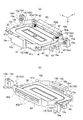
- FIG. 13 is an explanatory view showing a speaker device according to an embodiment of the present invention
- FIG. 13 (a) is a plan view
- FIG. 13 (b) is an XX sectional view
- FIG. 13 (c) is a rear view.
- Portions that are the same as those described above are assigned the same reference numerals, and redundant descriptions are omitted.
- the example shown in FIG. 10 is adopted as the vibration direction conversion unit 50, and the connection portion 53 is connected to the connection portion 60, and the vibration direction conversion portion 50 and the voice coil support portion 40 are connected via the connection portion 60. Has been.
- the voice coil support portion 40 is connected to the first connection portion 16a and the second connection portion 16b of the attachment unit 16 by the first holding portion 15A and the second holding portion 15B, respectively.
- the frame 12 as a stationary part supports the periphery of the diaphragm 10 via the edge 11, supports the magnetic circuit 20, and further supports the mounting unit 16 on the back side of the apparatus.
- the height of the magnetic circuit 20 is almost the entire height of the entire device, and the voice coil support portion 40 vibrates in the vicinity of the center of the magnetic circuit 20. And the end of the vibration direction changing part 50 are connected to each other at different heights via the connecting part 60. As a result, each link portion of the vibration direction conversion unit 50 can ensure a sufficient length within the height of the device, and a part of the height of the magnetic circuit 20 is set to the height of the vibration direction conversion unit 50. It is possible to fit in.
- FIG. 14 is an explanatory view showing an electronic apparatus including the speaker device according to the embodiment of the present invention.
- the electronic device 2 such as a mobile phone or a portable information terminal shown in FIG. 1A or the electronic device 3 such as a flat panel display shown in FIG. Since the space can be reduced, the entire electronic device can be made thinner. In addition, sufficient audio output can be obtained even in a thin electronic device.
- FIG. 15 is an explanatory view showing an automobile provided with a speaker according to an embodiment of the present invention.
- the space in the vehicle can be expanded by making the speaker device 1 thinner.
- the speaker device 1 according to the embodiment of the present invention is installed on the door panel, the protrusion of the door panel is eliminated and the operation space of the driver can be expanded. Also, since sufficient audio output can be obtained, music and radio broadcasting can be enjoyed comfortably in the car even during high-speed driving with a lot of noise.
Landscapes
- Physics & Mathematics (AREA)
- Engineering & Computer Science (AREA)
- Acoustics & Sound (AREA)
- Signal Processing (AREA)
- Audible-Bandwidth Dynamoelectric Transducers Other Than Pickups (AREA)
- Diaphragms For Electromechanical Transducers (AREA)
Abstract
大音量の再生音を放射することができる薄型のスピーカ装置を提供する。音声信号によって振動板10に振動を与える駆動部14を備え、駆動部14は、振動板10の振動方向とは異なる方向に沿って磁気ギャップ20Gを形成する磁気回路20と、磁気ギャップ20G内に支持されるボイスコイル30を有し磁気ギャップ20Gに沿って振動可能なボイスコイル支持部40と、ボイスコイル支持部40の振動を方向変換して振動板10に伝える剛性の振動方向変換部50とを備え、振動方向変換部50におけるボイスコイル支持部40側の端部50Aとボイスコイル支持部40の振動方向変換部側の端部40Aとの間に両端部の位置を振動方向に沿って異ならせて連結する連結部60を備える。
Description
本発明は、スピーカ装置に関するものである。
図1は、従来のスピーカ装置を示した説明図である。一般的なスピーカ装置として、ダイナミック型スピーカ装置が知られている(例えば、特許文献1参照)。このダイナミック型スピーカ装置は、例えば図1に示すように、フレーム3Jと、コーン形状の振動板21Jと、振動板21Jをフレーム3Jに支持するエッジ4Jと、振動板21Jの内周部に接合されたボイスコイルボビン610Jと、ボイスコイルボビン610Jをフレーム3Jに支持するダンパ7Jと、ボイスコイルボビン610Jに巻き回されたボイスコイル611Jと、ヨーク部51J,磁石52J,プレート53Jを備えると共に、ボイスコイル611Jが配置される磁気ギャップが形成された磁気回路とを有する。このスピーカ装置では、音声信号がボイスコイル611Jに入力されると、磁気ギャップ内のボイスコイル611Jに生じたローレンツ力によりボイスコイルボビン610Jが振動し、その振動によって振動板21Jが駆動される。
前述した一般的なダイナミック型スピーカ装置は、例えば図1に示すように、振動板21Jの音響放射側に対して反対側にボイスコイル611Jが配設され、ボイスコイル611J及びボイスコイルボビン610Jの振動方向と振動板21Jの振動方向が同じ方向になるように構成されている。そして、このようなスピーカ装置では、振動板21Jが振動するための領域、ボイスコイルボビン610Jが振動するための領域、磁気回路が配置される領域等が振動板21Jの振動方向(音響放射方向)に沿って形成されることになるので、スピーカ装置の全高が比較的大きく成らざるを得ない構造になっている。
詳細には、図1に示すように、スピーカ装置の振動板21Jの振動方向に沿った大きさは、コーン形状の振動板21Jの振動方向に沿った大きさ及び振動板21Jをフレーム3Jに支持するエッジ4Jの全高(a)、振動板21Jとボイスコイルボビン610Jとの接合部からボイスコイル611Jの上端までのボイスコイルボビン高さ(b)、ボイスコイル高さ(c)、磁気回路の主に磁石高さ(d)、磁気回路の主にヨーク部51Jの厚さ(e)等からなる。このようなスピーカ装置においては、充分な振動板21Jの振動ストロークを確保するためには、前述したa,b,c,dの高さを充分に確保する必要があり、また充分な駆動力を得るためには前述したc,d,eの高さを充分に確保する必要があるので、特に、大音量対応型スピーカ装置では、スピーカ装置の全高が大きく成らざるを得ない。
このように、従来のスピーカ装置では、ボイスコイルボビン610Jの振動方向と振動板21Jの振動方向とが同方向になっているので、振動板21Jの振幅を大きくして大音量を得ようとすると、ボイスコイルボビン610Jの振動ストロークを確保するためにスピーカ装置の全高が大きくなってしまい、装置の薄型化を達成し難い。すなわち、装置の薄型化と大音量化を両立し難い問題がある。
しかしながら、ボイスコイル611Jの振動を効率良く振動板21Jに伝達させるためには、ボイスコイル611Jの振動を直接振動板21Jに伝えること、すなわち、ボイスコイル611Jの振動方向と振動板21Jの振動方向とを一致させることが好ましい。ボイスコイル611Jの振動方向と振動板21Jの振動方向が異なる場合には、ボイスコイル611Jの振動が確実に振動板21Jに伝えられないことがあり、これがスピーカ装置の再生効率の悪化に繋がる問題が生じる。
一方、一般的なダイナミック型スピーカ装置では、コーン形状の振動板21Jの内周部にボイスコイルボビン610Jが接合されており、ボイスコイルボビン610Jから振動板21Jの内周部に駆動力が伝達されるので、振動板全体を略同位相にて駆動させることが比較的困難である。このため振動板全体を略同位相にて駆動することができるスピーカ装置が望まれている。
ところで、薄型スピーカ装置として、例えばコンデンサ型スピーカ装置が知られている。このコンデンサ型スピーカ装置は、振動板(可動電極)と固定電極とが向い合せに配置された構造を有する。このスピーカ装置は、電極間への直流電圧の印加により振動板が変位した状態となり、音声信号が重畳された信号が電極に入力されると、その信号に応じて振動板が振動する。しかし、このコンデンサ型スピーカ装置では、比較的大振幅の音声信号が入力されると、駆動力が非線形に著しく変化して、再生音の音質が比較的低くなる場合がある。
本発明は、このような問題に対処することを課題の一例とするものである。すなわち、比較的簡単な構造で大音量の再生音を放射することができる薄型のスピーカ装置を提供すること、ボイスコイルの振動を確実に振動板に伝えて再生効率の高いスピーカ装置を得ること、比較的簡単な構造で高音質な再生音を放射することができる薄型のスピーカ装置を提供すること、また、比較的簡単な構成で振動板が略同位相で振動する薄型のスピーカ装置を提供すること、等が本発明の目的である。
このような目的を達成するために、本発明によるスピーカ装置は、以下の独立請求項に係る構成を少なくとも具備するものである。
[請求項1]振動板と、前記振動板を振動方向に沿って振動自在に支持する静止部と、該静止部に設けられ、音声信号によって前記振動板に振動を与える駆動部とを備え、前記駆動部は、前記振動板の振動方向とは異なる方向に沿って磁気ギャップを形成する磁気回路と、前記磁気ギャップ内に支持されるボイスコイルと、前記ボイスコイルの振動を方向変換して前記振動板に伝える剛性の振動方向変換部とを備え、前記振動方向変換部における前記ボイスコイル側の端部と前記ボイスコイルの前記振動方向変換部側の端部との間に両端部の位置を前記振動方向に沿って異ならせて連結する連結部を備えることを特徴とするスピーカ装置。
[請求項1]振動板と、前記振動板を振動方向に沿って振動自在に支持する静止部と、該静止部に設けられ、音声信号によって前記振動板に振動を与える駆動部とを備え、前記駆動部は、前記振動板の振動方向とは異なる方向に沿って磁気ギャップを形成する磁気回路と、前記磁気ギャップ内に支持されるボイスコイルと、前記ボイスコイルの振動を方向変換して前記振動板に伝える剛性の振動方向変換部とを備え、前記振動方向変換部における前記ボイスコイル側の端部と前記ボイスコイルの前記振動方向変換部側の端部との間に両端部の位置を前記振動方向に沿って異ならせて連結する連結部を備えることを特徴とするスピーカ装置。
本発明の実施形態に係るスピーカ装置は、振動板と、前記振動板を振動方向に沿って振動自在に支持する静止部と、該静止部に設けられ、音声信号によって前記振動板に振動を与える駆動部とを備え、前記駆動部は、前記振動板の振動方向とは異なる方向に沿って磁気ギャップを形成する磁気回路と、前記磁気ギャップ内に支持されるボイスコイルと、前記ボイスコイルの振動を方向変換して前記振動板に伝える剛性の振動方向変換部とを備え、前記振動方向変換部における前記ボイスコイル側の端部と前記ボイスコイルの前記振動方向変換部側の端部との間に両端部の位置を前記振動方向に沿って異ならせて連結する連結部を備えることを特徴とする。
また、前記ボイスコイルの前記振動方向変換部側の端部の位置を前記振動方向変換部における前記ボイスコイル側の端部の位置に対して前記振動板よりに位置させることを特徴とする。
前記連結部は、剛性を備えることを特徴とする。連結部が剛性を備えることで、ボイスコイルと振動方向変換部の連結を変形無く行うことができ、ボイスコイルの振動を確実に方向変換して振動板に伝えることができる。また、前記連結部は、その上端部から下端部までの長さが、ボイスコイルの厚さより大きいことを特徴とする。連結部の厚さ内にボイスコイルの厚さが入ることで、ボイスコイルに周辺部材が接触する連結部の厚さで排除することが可能になる。
前記連結部は、前記ボイスコイルの幅方向に沿って延在することを特徴とする。前記連結部は、前記ボイスコイルの振動方向に沿って貫通する貫通孔を有することを特徴とする。
このような特徴のスピーカ装置では、音声信号が駆動部のボイスコイルに入力されると、磁気回路の磁気ギャップに配置されたボイスコイルにローレンツ力が生じて、ボイスコイルが、振動板の振動方向に対して異なる方向、好適には振動板の振動方向に対して直交する方向に沿って振動する。これに対して振動方向変換部が機能してボイスコイルの振動を方向変換して振動板に伝える。振動板は、振動方向変換部を介して伝達された駆動力によりボイスコイルとは異なる(例えば、ボイスコイルと直交する)振動方向に沿って振動する。
一般的なスピーカ装置では、例えば振動板の背面側にボイスコイルボビンが配置され、振動板の振動方向とボイスコイルボビンの振動方向とが同方向になるように構成されているために、振動方向に沿って振動板およびボイスコイルボビンが振動するための領域を要するので、スピーカ装置の音響放射方向に沿った幅(全高)が比較的大きい。
一方、本発明の実施形態に係るスピーカ装置では、振動板の振動方向に対して異なる方向、好適には、振動板の振動方向に対して直交する方向に形成された磁気ギャップを形成する磁気回路とその磁気回路に沿って振動するボイスコイル、更にはボイスコイルの振動方向を方向変換して振動板に伝える剛性の振動方向変換部を有するので、前述した一般的なスピーカ装置と比べて、音響放射方向に沿った幅が比較的小さい。つまり、薄型スピーカ装置を提供することができる。また、ボイスコイルの振動ストロークをスピーカ装置の全高に影響しない方向に設定できるので、ボイスコイルの振動ストロークすなわち振動板の振幅を大きくした場合であってもスピーカ装置の薄型化を達成しやすい。これによって、スピーカ装置の薄型化と大音量化を両立することが可能になる。
更に、本発明の実施形態に係るスピーカ装置では、振動方向変換部におけるボイスコイル側の端部とボイスコイルの振動方向変換部側の端部との間に両端部の位置を振動板の振動方向に沿って異ならせて連結する連結部を備えているので、振動方向変換部の高さ内にボイスコイルを振動させるための磁気回路の高さの一部を重ねることができ、振動板の振動方向に沿ったスピーカ装置の厚さを更に薄くすることが可能になる。
特に、ボイスコイルの振動方向変換部側の端部の位置を振動方向変換部におけるボイスコイル側の端部の位置に対して振動板よりに位置することで、ボイスコイルとの連結に制約されることなく振動方向変換部の高さを確保することができ、ボイスコイルの振動を大きく変換して振動板に伝えることが可能になる。
また、連結部をボイスコイルの幅方向に沿って延在させることで、ボイスコイルと振動方向変換部との連結を確実に行うことができると共に、連結部によってボイスコイルの幅方向の強度を補強することができる。
連結部にボイスコイルの振動方向に沿って貫通孔を設けることで、貫通孔で空気の流通がなされるので、ボイスコイル振動時に連結部に空気抵抗が作用してボイスコイルの振動を妨げる不具合が起こらない。これによって、連結部が振動の抵抗になるのを避けることができ、効率的にボイスコイルを振動させることができる。
以下、本発明の実施形態を図面に基づいて説明する。
[全体構成;図2~図4]
図2~図4は、本発明の実施形態に係るスピーカ装置の全体構成を示した説明図である(同図(a)がX軸方向に沿った断面図、同図(b)が駆動部の動作を示した説明図)。スピーカ装置1,1A,1Bは、振動板10と、振動板10を振動方向に沿って振動自在に支持するフレーム12と、フレーム12に設けられ、音声信号によって振動板10に振動を与える駆動部14とを備え、駆動部14は、振動板10の振動方向とは異なる方向に沿って磁気ギャップ20Gを形成する磁気回路20と、磁気ギャップ20G内に支持されるボイスコイル30を有し磁気ギャップ20Gに沿って振動可能なボイスコイル支持部40と、ボイスコイル支持部40の振動を方向変換して振動板10に伝える剛性の振動方向変換部50とを備える。図示においては、ボイスコイル支持部40の振動方向をX軸方向とし、それと直交する2方向をそれぞれY軸方向とZ軸方向としている。図示の例では、ボイスコイル30がボイスコイル支持部40に支持されているが、これに限らず、ボイスコイル30自体が剛性を有するように一体に振動するものであってもよい。
[全体構成;図2~図4]
図2~図4は、本発明の実施形態に係るスピーカ装置の全体構成を示した説明図である(同図(a)がX軸方向に沿った断面図、同図(b)が駆動部の動作を示した説明図)。スピーカ装置1,1A,1Bは、振動板10と、振動板10を振動方向に沿って振動自在に支持するフレーム12と、フレーム12に設けられ、音声信号によって振動板10に振動を与える駆動部14とを備え、駆動部14は、振動板10の振動方向とは異なる方向に沿って磁気ギャップ20Gを形成する磁気回路20と、磁気ギャップ20G内に支持されるボイスコイル30を有し磁気ギャップ20Gに沿って振動可能なボイスコイル支持部40と、ボイスコイル支持部40の振動を方向変換して振動板10に伝える剛性の振動方向変換部50とを備える。図示においては、ボイスコイル支持部40の振動方向をX軸方向とし、それと直交する2方向をそれぞれY軸方向とZ軸方向としている。図示の例では、ボイスコイル30がボイスコイル支持部40に支持されているが、これに限らず、ボイスコイル30自体が剛性を有するように一体に振動するものであってもよい。
振動板10は、図示のように、振動方向(Z軸方向)に沿って振動自在にフレーム12に支持されている。振動板10は、スピーカ駆動時、音響放射方向に音波を放射する。また、振動板10は、エッジ11を介してフレーム12に支持されており、振動方向以外の方向、詳細にはX軸方向やY軸方向に沿った移動は、エッジ11により規制されている。このエッジ11と振動板10は一体形成されてもよい。なお、本発明の実施形態では、ボイスコイル30の振動によって積極的に振動しない部位を静止部としている。したがって、フレーム12や磁気回路20の構成部材が静止部になり、振動板10は静止部に対して振動自在に支持されている。
振動板10の形成材料としては、例えば、樹脂系材料、金属系材料、紙系材料、セラミックス系材料、複合材料などを採用することができる。振動板10は、例えば剛性を有することが好ましい。振動板10は、例えば平板形状、ドーム形状、コーン形状などの規定形状に形成することができる。図示の例で振動板10は平板形状に形成されており、また、フレーム12の平面状の底面12Aに沿って支持されている。薄型化の実現を課題とする本発明の実施形態としては、平板形状の振動板10が特に好ましい。また、振動板10は、音響放射方向から視認した形状(平面形状)が、矩形状、楕円形状、円形状、多角形状など、規定形状に形成することができる。
また、必要に応じて、振動板10の表面(音響放射側の面)又は裏面(音響放射側とは逆側の面)に、突起部を形成しても構わない。突起部は振動板10の剛性を大きくする機能を有する。突起部は振動板10の表面に対し、直線状、環状、格子状に形成してもよく、例えば直線状の突起部を振動板の表面に複数形成するなど、適宜変更してもよい。
振動板10は、振動自在にフレーム12に支持されており、振動板10の背面側(音響放射方向とは逆側)における振動板10とフレーム12とで囲まれる空間が音響放射方向に対して遮断されている場合には、振動板10の背面側から発せられる音波が音響放射方向に向けて放射されるのを抑止できる。
エッジ11は、振動板10とフレーム12との間に配置され、内周部が振動板10の外周部を支持するとともに、外周部がフレーム12に接合することにより、振動板10を規定位置に保持する。詳細には、エッジ11は、振動板10を振動方向(Z軸方向)に沿って振動自在に支持するとともに、振動方向に直交する方向には制動する。図示のエッジ11は、音響放射方向から視認した場合、リング形状(環状)に形成されており、断面形状は規定形状、例えば凸形状、凹形状、波型形状などに形成されている。図示のエッジ11は、音響放射方向に凹形状に形成されているが、音響放射方向に凸形状に形成されても構わない。エッジ11は、例えば、皮,布,ゴム,樹脂,それらに目止め加工を施したもの、ゴムや樹脂などを規定の形状に成形した部材等を採用することができる。
駆動部14は、磁気回路20とボイスコイル支持部40と振動方向変換部50を備えている。磁気回路20は振動板10の振動方向(例えばZ軸方向)とは異なる方向(例えばX軸方向)に沿って磁気ギャップ20Gを形成している。図示の例では、振動板10の振動方向と直交する方向に沿って磁気ギャップ20Gを形成しているが、特にそれに限定されるものではない。ボイスコイル支持部40は、磁気ギャップ20G内に支持されるボイスコイル30を有し磁気ギャップ20Gに沿って振動するものである。ボイスコイル支持部40は後述する保持部によって動きが規制され、磁気ギャップ20Gに沿った方向のみの移動が許容されており、ボイスコイル30に音声信号SSが入力されると、磁気ギャップ20G内のボイスコイル30にX軸方向に沿ったローレンツ力が作用して、ボイスコイル30と一体のボイスコイル支持部40がX軸方向に沿って振動する。
フレーム12は、振動板10を振動方向に沿って振動自在に支持すると共に駆動部14を内部で支持している。また、フレーム12は後述する振動方向変換部50のリンク機構の一部を支持してリンク機構の動作に対してフレーム12からの反力を加える。このようなフレーム12は平面状の底面12Aを有していることが望ましい。
また、フレーム12は、前述したようにボイスコイル30の動作に対して静止している静止部でもある。ここでいう静止部は、ボイスコイル30の振動によって積極的に振動しない部位をいい、完全に静止している状態を必ずしも意図するわけでない。したがって、例えば、振動板10を支持できる程度に静止していればよく、スピーカ装置1,1A,1Bを駆動する際に生じる振動が伝搬して、その振動が静止部全体に生じていても構わない。本発明の実施形態における静止部は、フレーム12と磁気回路20の一部だけでなく、スピーカ装置1,1A,1Bが装着される被装着箇所、磁気回路20と機械的に一体となって配置される部材等が該当する。
振動方向変換部50は、ボイスコイル30の振動を方向変換して振動板10に伝えるものである。この振動方向変換部50は、剛性のリンク部分51を備えており、ボイスコイル30と振動板10との間に形成されたリンク部分51を角度変更させることによって、ボイスコイル30の振動を方向変換して振動板10に伝えている。
ボイスコイル30と振動方向変換部50は、連結部60を介して連結されている。ここでは、ボイスコイル支持部40が連結部60を介して振動方向変換部50と連結されているが、ボイスコイル30自体が剛性を有する構造物の場合にはボイスコイル30を直接連結部に接続することもできる。連結部60は、振動方向変換部50におけるボイスコイル支持部側の端部50Aとボイスコイル支持部40の振動方向変換部側の端部40Aとの間に形成され、両端部の位置を振動方向に沿って異ならせて連結させるものである。図示の例では、連結部60によって、ボイスコイル30の振動方向変換部50側の端部の位置を振動方向変換部50におけるボイスコイル30側の端部の位置に対して振動板よりに位置させている。これによると、ボイスコイル支持部40の配置(ボイスコイル30の配置)を振動方向変換部50の高さ方向にシフトさせることができ、磁気回路20の高さを振動方向変換部50の高さに含ませることができるので、全高を更に薄型化することが可能になる。また、全高の薄型化に際して、振動方向変換部50の高さを十分に確保することができるので、ボイスコイル30の振動を大きな振幅で振動板10の振動に変換することが可能になる。
図2に示した実施形態に係るスピーカ装置1では、振動方向変換部50は一つのリンク部分51によって形成されており、振動方向変換部50のボイスコイル支持部40側の端部50Aがリンク部分51を連結部60に連結する関節部52(52A)によって形成され、振動方向変換部50の振動板10側の端部50Bがリンク部分51を振動板10に連結する関節部52(52B)によって形成されている。関節部52は、リンク部分51と連結対象とを回転自在に連結するものであり、振動方向変換部50は、一端がボイスコイル30側に関節部52Aで角度変更自在に連結され、他端が振動板10側に関節部52Bで各同変更自在に連結され、ボイスコイル30の振動方向及び振動板10の振動方向のそれぞれに対して斜設されたリンク部分51を有するリンク機構を備えている。
図2(b)に示すように、ボイスコイル30の振動に伴って、ボイスコイル30側の関節部52Aはボイスコイル支持部40の移動に沿ってX軸方向に移動し、振動板10側の関節部52Bは振動板10の振動方向(例えばZ軸方向)に沿って移動する。連結部60の底面61がフレーム12の底面12Aに沿って接触することなくスライドすることで、ボイスコイル30の振動を円滑に行うことが可能になると共に、接触による異音の発生を抑止することができる。
図3に示した実施形態に係るスピーカ装置1Aでは、振動方向変換部50は剛性の第1のリンク部分51Aと第2のリンク部分51Bを備えたリンク機構50Lによって形成されている。振動方向変換部50のボイスコイル支持部40側の端部50Aが第1のリンク部分51Aを連結部60に連結する関節部52Aによって形成され、振動方向変換部50の振動板10側の端部50Bが第1のリンク部分51Aを振動板10に連結する関節部52Bによって形成されている。第1のリンク部分51Aと第2のリンク部分51Bはボイスコイル支持部40の振動方向に対して異なる方向に傾斜配置され、第2のリンク部分51Bの一端は第1のリンク部分51Aの中間に関節部52Cで連結されており、第2のリンク部分51Bの他端は静止部13となるフレーム12の底部12Aに関節部52Dで連結されている。ここで静止部13は、振動方向変換部50に対して振動板10側とは逆側に設けられている。
図3(b)に示すように、関節部52A,52B,52C,52Dは、第1のリンク部分51A,第2のリンク部分51Bと連結対象とを回転自在に連結するものであり、ボイスコイル支持部40側の関節部52Aはボイスコイル支持部40の移動に沿ってX軸方向に移動し、静止部13に連結された関節部52Dは固定された状態になり、静止部13から受ける反力によって、関節部52Aの移動が第1のリンク部分51Aと第2のリンク部分51Bの角度変化に変換され、振動板10側の関節部52Bを振動板10の振動方向(例えばZ軸方向)に移動させる。
図4に示した実施形態に係るスピーカ装置1Bは、図3に示した駆動部14を左右対称に互いに対向配置したものであり、駆動部14(R),14(L)を備え、それぞれの駆動部14(R),14(L)にリンク機構50L(R),50L(L)とボイスコイル支持部40(R),40(L)と磁気回路20(R),20(L),連結部60(R),60(L)を設けている。
これによると、図4(b)に示すように、ボイスコイル支持部40(R),40(L)の振動方向を同期させた逆向きにすることで、2つの駆動部14(R),14(L)の駆動力を合わせて振動板10を振動させることができる。また、振動板10側の関節部52Bを複数箇所に設けることができるので、振動板10の支持点が増え、振動板10の振動の位相を合わせ、略同位相で振動板10を振動させることが可能になる。また、ボイスコイル支持部40(R),40(L)が例えば互いに対向して水平方向に振動する場合には、これによって水平方向の振動が打ち消し合うので、振動板10に水平方向の振動が伝わるのを抑止することができる。
このような本発明の実施形態に係るスピーカ装置1,1A,1Bによると、音声信号SSが入力されると、振動板10の許容される振動方向とは異なる方向に沿って形成された磁気ギャップ20Gに沿ってボイスコイル支持部40が振動することになり、この振動が振動方向変換部50によって方向変換されて振動板10に伝達されることになって、振動板10を振動させて音響放射方向SDに音声信号SSに応じた音が放射される。
この際、磁気ギャップ20Gの方向を振動板10の振動方向及びスピーカ装置1,1A,1Bの厚さ方向に交差させているので、磁気回路20の駆動力或いはボイスコイル支持部40の振動ストロークを大きくすることが直接的にスピーカ装置1,1A,1Bの厚さ方向(Z軸方向)の大きさに影響を与えない。よって、大音量化を図りながらスピーカ装置1,1A,1Bの薄型化を実現することが可能になる。
また、振動方向変換部50は、機械的なリンク機構によってボイスコイル支持部40の振動方向を変換して振動板10に伝えているので、振動の伝達効率が高い。特に、図3及び図4に示した実施形態に係るスピーカ装置1A,1Bでは、第1のリンク部分51Aと第2のリンク部分51Bの角度変更がボイスコイル支持部40の振動と静止部13からの反力によって行われるので、より確実にボイスコイル支持部40からの振動を振動板10に伝えることができる。これによって、スピーカ装置1A,1Bの良好な再生効率を得ることができる。
そして、連結部60を設けることで、ボイスコイル支持部40の端部40Aの位置と振動方向変換部50の端部50Aの位置との間に段差を形成することができる。これによって、磁気回路20のZ軸方向の幅(高さ)を振動方向変換部50の高さの中に収めることができ、駆動力を確保する上で必要になる磁気回路20の高さを十分に確保しながら、スピーカ装置1~1Bを薄型化することが可能になる。また、連結部60を設けることでスピーカ装置1~1Bの薄型化を達成しても十分に振動方向変換部50の必要高さ(リンク部分51の長さ)を確保することができ、振動板10の大きな振幅を得ることが可能になる。
更には、連結部60の底面61がフレーム12の底面12A或いは静止部13上に沿ってスライドするように形成することで、ボイスコイル支持部40の振動を安定化することが可能になると共に、振動方向変換部50の端部50Aの移動を直線的に行うことができ、振動板10に連結される振動方向変換部50の端部50Bの動きを確実且つ安定化することができる。連結部60の底面61がフレーム12の底面12A或いは静止部13に接触しないようにすることで、ボイスコイル30の円滑な振動を可能にして、スピーカ装置駆動時の異音の発生を抑止することができる。
以下、図5~図11によって、本実施形態に係るスピーカ装置の各構成要素についての具体的な態様を説明する。
[ボイスコイル支持部,連結部,保持部,取り付けユニット;図5]
図5は、ボイスコイル支持部,連結部,保持部,取り付けユニットを説明する説明図(同図(a)がX軸方向とY軸方向の中間方向からみた斜視図、同図(b)がその逆向きからみた斜視図)である。ここでは、ボイスコイル支持部40及び連結部60を直接又は他の部材を介してフレームに保持する或いはフレームに取り付けるための具体的な構造を説明する。
図5は、ボイスコイル支持部,連結部,保持部,取り付けユニットを説明する説明図(同図(a)がX軸方向とY軸方向の中間方向からみた斜視図、同図(b)がその逆向きからみた斜視図)である。ここでは、ボイスコイル支持部40及び連結部60を直接又は他の部材を介してフレームに保持する或いはフレームに取り付けるための具体的な構造を説明する。
ボイスコイル支持部40は、その振動方向の一端に連結部60が取り付けられ、連結部60はボイスコイル支持部40の幅に沿って延在するように取り付けられている。ボイスコイル支持部40は平板状の絶縁平面板41にボイスコイル取り付け箇所41aが形成され、そのボイスコイル取り付け箇所41aにボイスコイル30が取り付けられている。ボイスコイル支持部40におけるボイスコイル30の内側には開孔部41bが形成され、ボイスコイル支持部40の軽量化を図っている。
ボイスコイル支持部40を構成する材料には、樹脂系材料(接着用樹脂、硬化型樹脂等を含む)、金属系材料、セラミックス系材料、複合材料などを採用することができ、ボイスコイルの形状を変化させない程度に剛性を付与させる材料であれば、特に限定されない。前述したように、図示の説明ではボイスコイル支持部40に連結部60が連結されている例を示しているが、これに限らず、ボイスコイル30自体が剛性を備えていれば、ボイスコイル支持部40が不要となるので、連結部60を直接的にボイスコイル30に連結しても構わない。この場合には、適宜、ボイスコイル30に対し、連結部60又は振動方向変換部50が電気的に絶縁されるなどの処置を施すことが好ましい。
連結部60には、振動方向変換部50の端部50A(後述する接続部53)が接続される接続孔60sが形成されると共に、ボイスコイル支持部40の振動方向に沿って貫通する貫通孔60pが形成されている。貫通孔60pはボイスコイル支持部40の振動に対して連結部60が抵抗(音響上の機械抵抗)になるのを避けるために形成される通気孔である。
このボイスコイル支持部40及び連結部60は保持部15によって直接又は他の部材を介してフレーム12に保持される。保持部15は、ボイスコイル支持部40のX軸方向に沿った移動を許容しながらそれ以外の方向への移動を規制するための構造を備えており、具体的には、Z軸方向に沿った厚みを有する板材でX軸方向に沿った凸状の湾曲が形成され、湾曲の曲げ伸ばし方向に関する変形を許容しながらそれ以外の変形を規制している。
保持部15は、一端がボイスコイル支持部40又は連結部60に接続され、他端が取り付けユニット16に接続されるか、或いは、その中間部がボイスコイル支持部40又は連結部60に接続され、その両端が取り付けユニット16に接続されている。ここでは取り付けユニット16を介してボイスコイル支持部40又は連結部60をフレーム12に保持しているが、これに限らず、直接保持部15の端部をフレーム12に接続してもよい。
図示の例では、保持部15は第1の保持部15Aと第2の保持部15Bとを備えており、第1の保持部15Aと第2の保持部15Bは、取り付けユニット16を介してボイスコイル支持部40をフレーム12に保持している。第1の保持部15Aは連結部60を取り付けユニット16に保持しており、左右それぞれに設けられた第1の保持部15Aの内側の端部が連結部60の両外側の端部に接続され、各第1の保持部15Aの外側の端部が取り付けユニット16にそれぞれ接続されている。より具体的には、連結部60の両外側端部には係合突起60a,60aが形成されており、第1の保持部15Aの内側の端部には係合突起60a,60aに係合する係合孔15a,15aが形成されている。また、取り付けユニット16には連結部60の左右両側に第1の接続部16a,16aが形成されており、第1の保持部15Aの外側の端部には第1の接続部16a,16aの係合突起16a1,16a1に係合する係合孔15aが形成されている。
第2の保持部15Bは、図示の例では、一部材の中央部が取り付けユニット16の第2の接続部16bに接続され、その両端がボイスコイル支持部40の左右端に接続されている。第2の接続部16bには係合突起16b1が形成され、この係合突起16b1に第2の保持部15Bの係合孔15bが係合されている。ボイスコイル支持部40の左右端には係合突起41c,41cが形成され、この係合突起41c,41cに第2の保持部15Bの両端に形成された係合孔15bが係合している。ここでは、第2の保持部15Bをボイスコイル支持部40の幅内に配置して、ボイスコイル支持部40の保持機構がボイスコイル支持部40の幅方向に嵩張らないようにしている。スペースに余裕が有る場合には、第2の接続部16bを第1の接続部16aと同様に左右両側に配置して、ボイスコイル支持部40の左右端をそれぞれ第2の保持部15Bを介して左右の第2の接続部16bに接続するようにしてもよい。
取り付けユニット16は、第1の保持部15Aの端部が接続される第1の接続部16aが連結部60の左右両側に設けられ、第2の保持部15Bが接続される第2の接続部16bがボイスコイル支持部40の後方に設けられ、第1の接続部16aと第2の接続部16bとを一体に支持する一体支持部16cを有する。また、フレーム12に対して取り付けられる取り付け係止部16d或いは取り付け係止孔16eを備えており、ホイスコイル支持部40と連結部60と保持部15(第1の保持部15A,第2の保持部15B)と取り付けユニット16とをユニット化して1工程の取り付け作業でフレーム12に組み込むことができるようにしている。
また、このような実施形態では、取り付けユニット16の第1の接続部16aが音声信号入力端子を兼ねるようにし、音声信号が第1の保持部15Aを介してボイスコイル30に供給されるようにすることができる。この場合には、第1の保持部15Aに信号線を沿わせるか、第1の保持部15Aをフレキシブル配線板とするか、或いは第1の保持部15Aを導電性材料で形成してこれ自体を信号線とするかのいずれかにすることができる。そして、ボイスコイル30からのボイスコイル引き出し線43を絶縁平面板41上に形成し、このボイスコイル引き出し線43の先端をボイスコイル接続端子42に電気的に接続し、ボイスコイル接続端子42を第1の保持部15Aの信号線端子に電気的に接続する。なお、ボイスコイル30に音声信号を供給する配線を、例えば、従来から使用される錦糸線等、第1の保持部以外の部材を別途配置する場合には、第1の保持部15Aにボイスコイル接続端子42や、音声信号入力端子である第1の接続部16aを電気的に接続する必要はない。
このような音声信号の入力配線経路を形成することで、入力信号線の配線スペースを省くことができ、装置内でのスペース効率を高めることができる。また、ボイスコイル支持部40の振動時にも信号線の暴れが無く、信号線が装置内の各部に接触して異音を発する不具合も生じない。
[ボイスコイル支持部と磁気回路;図2~図4,図6~図8]
ボイスコイル支持部40を振動させるための磁気回路20は、ボイスコイル支持部40の振動方向に沿った磁気ギャップ20Gを形成しているだけでなく、ボイスコイル支持部40上で平面的に巻かれたボイスコイル30を流れる電流に対して同方向のローレンツ力を与えるために、磁気ギャップ20Gが逆向きで一対の磁場を形成している。
ボイスコイル支持部40を振動させるための磁気回路20は、ボイスコイル支持部40の振動方向に沿った磁気ギャップ20Gを形成しているだけでなく、ボイスコイル支持部40上で平面的に巻かれたボイスコイル30を流れる電流に対して同方向のローレンツ力を与えるために、磁気ギャップ20Gが逆向きで一対の磁場を形成している。
図2~図4に示した例では、磁気回路20は、磁石21(21A,21B)とヨーク部22(22A,22B)によって形成されており、Z軸方向で互いに逆向きの磁極を有する一対の磁石21A,21BをX軸方向の所定間隔で並べて配置し、一対の磁石21A,21Bとヨーク部22Bとの間に前述した磁気ギャップ20Gを形成している。そして磁石21A,21B上を流れる電流がY軸方向で互いに逆方向になるようにボイスコイル30を巻き回すことで、ボイスコイル30にX軸方向に沿ったローレンツ力が働くようにしている。
磁石21とヨーク部22の配置を変えても、前述と同様な機能を有する磁気回路20を形成することができる。図6及び図7に示した例では、磁気回路20は、複数の磁石21(21A~21D)を有する。この磁気回路20では、磁石21が、磁気ギャップ20Gの磁場の方向に沿った両側に設けられている。
図示の例では、ヨーク部22は、下側のヨーク部22A、上側のヨーク部22B、および支柱部22Cを有する。ヨーク部22A,22Bは規定間隔をあけて略平行に配置されており、中央部には、支柱部22Cがヨーク部22A,22Bに対して略直交する方向へ延在するように形成されている。
ヨーク部22A,22Bには磁石21A~21Dが配置され、磁石21Aと磁石21Cとで一つの磁気ギャップ20G2が形成され、磁石21Bと磁石21Dとでもう一つの磁気ギャップ20G1が形成されている。この一対の磁気ギャップ20G1と磁気ギャップ20G2は、平面的に並べて形成され、互いに逆方向の磁場が形成されるようになっている。
一方、ボイスコイル30は、平面形状が略矩形状に形成されており、Y軸方向に沿って形成された直線部30A,30Cと、X軸方向に沿って形成された直線部30B,30Dにより構成されている。ボイスコイル30の直線部30A,30Cは、磁気回路20の磁気ギャップ20G内に配置され、磁場の方向がZ軸方向に沿うように規定されている。ボイスコイル30の直線部30B,30Dには磁場を印加しないほうが好ましい。また、直線部30B,30Dに磁場が印加されている場合でも、その直線部30B,30Dに生じるローレンツ力が互いに相殺するように構成されている。ボイスコイル30は、巻き数を比較的多くすることで、磁気ギャップ20G中の部分を比較的大きくすることができ、スピーカ駆動時、比較的大きな駆動力を得ることができる。
磁気回路20は、図7に示す例では、ボイスコイル30の直線部30Aにかかる磁場の向きが、直線部30Cに係る磁場の向きに対して逆向きとなるように、複数の磁石21A~21Dに対して、磁石21Aと磁石21Cが同方向に着磁され、磁石21Bと磁石21Dがそれとは逆の同方向に着磁されている。磁石21の着磁は磁石21とヨーク部22とを組み付けた後に行うことができるが、図2~図4及び図6,図7に示した例ではその際の着磁工程を2回行うことが必要になる。
これに対して、図8に示す例では、磁気ギャップ20G2を同方向に着磁された磁石21A,21Cによって形成し、磁気ギャップ20G1はヨーク部22A,22Bのそれぞれに形成したヨーク凸部22a,22b間に形成している。これによると、磁石21とヨーク部22とを組み付けた後に行う着磁工程を1回で済ませることができ、工程の簡略化が可能になる。
[振動方向変換部;図3,図4,図9~図11]
図3及び図4に示した例では、振動方向変換部50は、第1のリンク部分51A,第2のリンク部分51B,関節部52A,52B,52C,52Dによってリンク機構50Lが形成されている。この例では第2のリンク部分51Bと静止部13との関節部52Dが位置変位しない関節部であって、他の関節部52A,52B,52Cは位置が変位する関節部になっている。これによって、全体のリンク機構50Lは関節部52Dにおいて静止部13からの反力を受ける構造になっている。このリンク機構50Lでは、関節部52Aがボイスコイル支持部40の振動によってX軸方向に移動すると、関節部52BはZ軸方向に沿って移動することになり、ボイスコイル支持部40の振動を方向変換して振動板10に伝える。
図3及び図4に示した例では、振動方向変換部50は、第1のリンク部分51A,第2のリンク部分51B,関節部52A,52B,52C,52Dによってリンク機構50Lが形成されている。この例では第2のリンク部分51Bと静止部13との関節部52Dが位置変位しない関節部であって、他の関節部52A,52B,52Cは位置が変位する関節部になっている。これによって、全体のリンク機構50Lは関節部52Dにおいて静止部13からの反力を受ける構造になっている。このリンク機構50Lでは、関節部52Aがボイスコイル支持部40の振動によってX軸方向に移動すると、関節部52BはZ軸方向に沿って移動することになり、ボイスコイル支持部40の振動を方向変換して振動板10に伝える。
本発明の実施形態に係る振動方向変換部50は、線状の屈折部を有する板状部材によって形成することができ、この屈折部を前述したリンク機構50Lの関節部にすることができる。すなわち、図示の例では、第1のリンク部分51A及び第2のリンク部分51Bを板状部材によって形成し、リンク機構50Lの関節部52A,52B,52C,52Dを線状の屈折部によって形成することができる。これによると、振動板10との接合部分を線状に接合することができるので、平面状の振動板10に対して幅方向に沿って均一に振動を加えることができ、振動板全体を略同位相で振動させることが可能になる。すなわち、分割振動の発生を抑えて特に高音域側の再生が可能になる。また、各リンク部分は剛性を有するので、固有振動モードでの振動が発生しにくく、リンク部分のたわみ振動等が振動板10の振動へ悪影響を与えるのを抑止し、音響特性が低減することを抑止できる。
本実施形態に係る振動方向変換部50は、図示はしていないが、例えば通気孔を形成しても良い。通気孔は、スピーカ振動時の振動板10とフレーム12で囲まれる空間の空気圧の局所的な変動を低減することができ、空気圧による振動方向変換部50の制動を抑止する。また、通気孔によって例えばリンク部分に中抜きが形成されて、リンク部分を軽量化できるので、これによって高域再生が可能になる。また、振動方向変換部の軽量化は特に再生特性の広域化や、所定の音声電流に対する音波の振幅及び音圧レベルを大きくすることに有効である。
また、振動方向変換部50は、屈折部で繋がった一体部品からなるようにしてもよい。この場合は、複雑なリンク機構を形成する振動方向変換部50を即座にボイスコイル支持部40や振動板10に接合することができ、装置の組立性が良好になる。また、振動方向変換部50は例えばボイスコイル30(ボイスコイル支持部40を含む)や振動板10と一体に形成することも可能である。
関節部52A,52B,52C,52Dは、機械的な構造の関節(ジョイント)で構成されていてもよいし、ポリエステルやポリアラミド等の高分子からなる繊維にて構成される部材、ポリウレタン樹脂やゴム等からなる部材、可撓性フィルムなどの可撓性部材により構成されていてもよい。また、例えば、ボイスコイル30と振動方向変換部50とが樹脂材料などの規定材料により一体形成されて、所定箇所に折り曲げ自在になるように加工処理を施して関節部52A,52B,52C,52Dを形成してもよい。
図9は、本発明の実施形態における振動方向変換部50の動作を説明するための説明図である。詳細には、図9(b)は振動板10が基準位置に位置した状態の振動方向変換部50の状態、図9(a)は振動板10が基準位置に対して音響放射側に変位している状態の振動方向変換部50の状態、図9(c)は振動板10が基準位置に対して音響放射側に対して反対方向に変位している状態の振動方向変換部50の状態を示している。
前述したように、関節部52Dが唯一位置変動しない関節部であり、これが静止部13(或いはフレーム12)に対して支持され、静止部13からの反力をリンク機構50Lに付与している。これによって、ボイスコイル支持部40が基準位置X0からX軸方向にX1だけ移動すると、図9(a)に示すように、異なる方向に傾斜配置している第1のリンク部分51Aと第2のリンク部分51Bの角度がほぼ同角度立ち上がることになり、関節部52Dで静止部13からの反力を受けて関節部52Bは確実に振動板10を基準位置Z0からZ軸方向にZ1だけ押し上げる。また、ボイスコイル支持部40が基準位置X0からX軸と逆方向にX2だけ移動すると、図9(c)に示すように、第1のリンク部分51Aと第2のリンク部分51Bの角度がほぼ同角度下がることになり、関節部52Dで静止部13からの反力を受けて関節部52Bは確実に振動板10を基準位置Z0からZ軸と逆方向にZ2だけ押し下げる。
ここで、関節部52Aから関節部52Cまでのリンク部分の長さaと関節部52Cから関節部52Bまでのリンク部分の長さbと関節部52Cから関節部52Dまでのリンク部分の長さcを等しくして、ボイスコイル支持部40の移動方向と平行に関節部52Aと関節部52Dを配置していることが好ましい。このようなリンク機構はスコットラッセルの機構として知られており、関節部52A,52B,52Cは関節部52Dを中心として直径が第1のリンク部分70の長さ(a+b=2a)の円周上にある。すなわち、関節部52Aと関節部52Dを通る直線と、関節部52Bと関節部52Dを通る直線とがなす角は常に直角になる。これによって、ボイスコイル支持部40をX軸方向に移動させると、第1のリンク部分51Aと振動板10との関節部52Bは常にX軸と垂直なZ軸に沿って移動することになり、ボイスコイル支持部40の振動方向をそれとは垂直方向に変換して振動板10に伝えることができる。
図10は、本発明の実施形態における振動方向変換部50の一例を示す説明図である(同図(a)が側面図、同図(b)が斜視図、同図(c)が分解斜視図)。この振動方向変換部50は、駆動部を一対設けて、振動方向変換部50を互いに略左右対称に対向配置させる場合であって、しかも振動方向変換部50を一体部品で形成している。
この実施形態に係る振動方向変換部50は、一端を連結部60との関節部52A(R),52A(L)とし、他端を振動板10との関節部52B(R),52B(L)とする一対の第1のリンク部分51A(R),51A(L)を有する。また、一端を第1のリンク部分51A(R),51A(L)の中間部との関節部52C(R),52C(L)とし、他端を静止部(後述する第6のリンク部分51F)との関節部52D(R),52D(L)とする一対の第2のリンク部分51B(R),51B(L)を有する。更に、連結部60から一体的に延設される一対の第3のリンク部分51C(R),51C(L)と、振動板10に沿って固着される第4のリンク部分51Dとを有する。また、一端を第3のリンク部分51C(R),51C(L)の端部との関節部52E(R),52E(L)とし、他端を第4のリンク部分51Dとの関節部52F(R),52F(L)とする一対の第5のリンク部分51E(R),51E(L)を有する。そして、第4のリンク部分51Dの両端に第1のリンク部分51Aと振動板10(第4のリンク部分51D)との関節部52B(R),52B(L)を形成し、第2のリンク部分51B(R),51B(L)と静止部(後述する第6のリンク部分51F)との関節部52D(R),52D(L)を第4のリンク部分51Dとほぼ等しい長さの第6のリンク部分51Fの両端に形成する。更には、第1のリンク部分51A(R)と第5のリンク部分51E(R)又は第1のリンク部分51A(L)と第5のリンク部分51E(L)が平行リンクを形成し、第3のリンク部分51C(R),51C(L)と第4のリンク部分51Dがそれぞれ平行リンクを形成する。また、第3のリンク部分51Cの基端部には連結部60との接続部53(R),(L)が形成されている。接続部53は前述した連結部60の接続孔60sに挿入接続される。
このような振動方向変換部50のリンク機構50Lは、実質的は、図4に示した実施形態のリンク機構と平行リンク機構を組み合わせた機能を有し、各リンク部分を板状部材によって形成し、リンク部分間の各関節部は線状の屈折部によって形成してリンク部分相互間が屈折部を介して一体的に形成されている。
この振動方向変換部50の動作を図11によって説明する。この例ではフレーム12に支持される第6のリンク部分51Fが静止部13として機能することになる。このような振動方向変換部50によると、ボイスコイル支持部40の振動による連結部60の移動によって、関節部52A(R),(L)がX軸方向の基準位置X0からX1に移動すると、これによって平行リンクを形成している第3のリンク部分51C(R),(L)と第4のリンク部分51Dは平行状態を維持して上昇し、平行リンクを形成している第1のリンク部分51A(R),(L)と第5のリンク部分51E(R),(L)が立ち上がるように角度変更する。その際、関節部52D(L),(R)が静止部となる第6のリンク部分51Fに支持されているので、静止部からの反力を受けて第1のリンク部分51A(R),(L)と第5のリンク部分51E(R),(L)の角度変更が確実に行われ、関節部52A(R),(L)の位置X0から位置X1への変位を振動板10の位置Z0から位置Z1への変位に確実に変換する。
同様に、関節部52A(R),(L)がX軸方向の基準位置X0からX2に移動すると、これによって平行リンクを形成している第3のリンク部分51C(R),(L)と第4のリンク部分51Dは平行状態を維持して下降し、平行リンクを形成している第1のリンク部分51A(R),(L)と第5のリンク部分51E(R),(L)が倒れるように角度変更を行う。その際、関節部52D(R),(L)が静止部に支持されているので、静止部からの反力を受けて第1のリンク部分51A(R),(L)と第5のリンク部分51E(R),(L)の角度変更が確実に行われ、関節部52A(R),(L)の位置X0から位置X2への変位を振動板10の位置Z0から位置Z2への変位に確実に変換する。
このような実施形態によると、一つのボイスコイル支持部40のX軸方向の振動が、略同位相・略同振幅で振動する関節部52B(R),(L),52F(R),(L)及び第4のリンク部分51DにおけるZ軸方向の振動に変換されることになる。これによって、振動板10は、広い範囲で支持されて略同位相・略同振幅の振動が与えられることになるので、面積が広い平面的な振動板10に対してボイスコイル支持部40の振動を略同位相で伝達することができる。
このような振動方向変換部50のリンク機構は、前述したように各リンク部分を板状部材によって形成することができ、各関節部分はリンク部分相互を回転可能に接合したものであっても良いし、リンク部分相互が屈折自在又屈曲自在に連結又は一体化しているものであっても良い。板状部材は、剛性が高く軽量の部材が好ましく、繊維強化プラスチックフィルム等を用いることができる。
図10(b)に示すように、第3のリンク部分51C(R),(L),第4のリンク部分51D,第5のリンク部分51E(R),(L)をそれぞれ一対に平行配置しており、第1のリンク部分51A(R),(L)を二股に形成してその中間部に第2のリンク部分51B(R),(L)との関節部52C(R),(L)が形成され、第2のリンク部分51B(R),(L)及び第6のリンク部分51Fは、一対に平行配置されている第3のリンク部分51C(R),(L),第4のリンク部分51D,第5のリンク部分51E(R),(L)の間に配備されている。
このようにリンク部分を1つの板状部材で形成することで、振動板10を面で支持して振動させることができるので、振動板10全体を略同位相で振動させることができ、分割振動を抑制することが可能になる。また、リンク部分を複数の板状部材で形成することもできるが、1つの板状部材で形成することで製造工程を簡略化することができる。リンク部分を1つの板状部材で形成する際、1つの平面状の板状部材からリンク部材を切り出しても構わない。
図10(b)に示すように、この実施形態の振動方向変換部50は、リンク部分を形成する一つの板状部材全体を凸台形状に屈折させて第1のリンク部分51A(R),(L)と第4のリンク部分51Dを形成し、この板状部材を部分的に切り出して凹台形状に屈折させて第2のリンク部分51B(R),(L)と第6のリンク部分51Fを形成している。
また、この振動方向変換部は、図10(c)に示すように、2枚の板状部材501,502を貼り合わせて形成し、一方の板状部材501に第1のリンク部分51A(R),(L),第2のリンク部分51B(R),(L),第4のリンク部分51D,第6のリンク部分51Fを形成し、他方の板状部材502に、第3のリンク部分51C(R),(L)と第5のリンク部分51E(R),(L)を形成している。そして、第1のリンク部分51A(R),(L)と第4のリンク部分51Dに沿って第3のリンク部分51C(R),(L)と第5のリンク部分51E(R),(L)を形成すると共に、第2のリンク部分51B(R),(L)と第6のリンク部分51Fに対応する開口502Aが板状部材502に形成されている。
図10(c)に示す例では、第2のリンク部分51B(R),(L)と第6のリンク部分51Fに対応する他方の板状部材502に形成される開口502Aの大きさが、他方の板状部材502の一端から内側に向かって拡大するように形成されている。このようにすることで、第2のリンク部分51B(R),(L)と第6のリンク部分51Fが他の板状部材502に接触することが無く、リンク機構の動きを円滑に行わせることができる。開口502Aは、必要に応じてその形状を適宜変更しても構わなく、他方の板状部材502の一端から内側に向かって略同じ幅にしても構わない。
また、各関節部の近傍において、各リンク部分の端部には傾斜面が形成されている。特に、傾斜面はリンク部分が関節部において屈折する際に、互いに近づき合うリンク部分の側面とは逆側の側面に形成されており、リンク部分が関節部において効率良く屈折できるように形成されている。
このような実施形態では、2つの対向するボイスコイル支持部40に対して一つの一体部品の装着のみで振動方向変換部のリンク機構を形成することができるので、一対の駆動部を備えたスピーカ装置を形成する場合にも組み立て作業を簡易に行うことができる。また、静止部に支持される第6のリンク部分51Fを設けることで、ボイスコイル支持部40の対向振動(複数のボイスコイル支持部40が互いに逆方向となるように振動すること)に対しては、特に関節部52D(R),(L)をフレーム12に支持しなくても、この関節部52D(R),(L)の位置が常に一定に保持されることになり、これによっても振動方向変換部のスピーカ装置への組み込みを簡易化することができる。
そして、リンク機構としては、右側の第1のリンク部分51A(R)と第3のリンク部分51C(R)、左側の第1のリンク部分51A(L)と第3のリンク部分51C(L)によって平行リンクが形成されているので、ボイスコイル支持部40の対向振動に対して振動板10に固着される第4のリンク部分51DをZ軸方向に沿って安定に平行移動させることができる。これによって、平面状の振動板10に対して安定した振動を加えることが可能になる。
図12に示す実施形態は、図10に示した実施形態の改良例である。図12(a)に示す例では、ボイスコイル支持部40の対向振動によって曲げが生じ易いリンク部分に対して凸部510を設けて剛性を高めている。図示の例では、第1のリンク部分51A(R),(L),第2のリンク部分51B(R),(L),第3のリンク部分51C(R),(L),第6のリンク部分51Fにそれぞれ凸部510が設けられている。また、同図(b)に示す例では、特に強度を必要としないリンク部分において開口部520を設けて振動方向変換部の軽量化を図っている。図示の例では、第4のリンク部分51Dに開口部520が設けられている。振動方向変換部の軽量化は特に再生特性の広域化や、所定の音声電流に対する音波の振幅及び音圧レベルを大きくすることに有効である。
[実施例と搭載例;図12~図14]
図13は、本発明の実施例に係るスピーカ装置を示した説明図である(同図(a)が平面図、同図(b)がX-X断面図、同図(c)が背面図)。前述した説明と共通する部分は同一符号を付して重複説明を省略する。振動方向変換部50としては図10に示した例を採用しており、その接続部53が連結部60に接続され、連結部60を介して振動方向変換部50とボイスコイル支持部40が接続されている。ボイスコイル支持部40は第1の保持部15Aと第2の保持部15Bによって取り付けユニット16の第1の接続部16aと第2の接続部16bにそれぞれ接続されている。静止部であるフレーム12は、振動板10の周囲をエッジ11を介して支持すると共に、磁気回路20を支持し、更には装置の背面側で取り付けユニット16を支持している。
図13は、本発明の実施例に係るスピーカ装置を示した説明図である(同図(a)が平面図、同図(b)がX-X断面図、同図(c)が背面図)。前述した説明と共通する部分は同一符号を付して重複説明を省略する。振動方向変換部50としては図10に示した例を採用しており、その接続部53が連結部60に接続され、連結部60を介して振動方向変換部50とボイスコイル支持部40が接続されている。ボイスコイル支持部40は第1の保持部15Aと第2の保持部15Bによって取り付けユニット16の第1の接続部16aと第2の接続部16bにそれぞれ接続されている。静止部であるフレーム12は、振動板10の周囲をエッジ11を介して支持すると共に、磁気回路20を支持し、更には装置の背面側で取り付けユニット16を支持している。
この実施例によると、磁気回路20の高さがほぼ装置全体の全高になっており、その磁気回路20の中心付近をボイスコイル支持部40が振動する構造になっており、ボイスコイル支持部40の端部と振動方向変換部50の端部とが連結部60を介して異なる高さで接続されている。これによって、振動方向変換部50の各リンク部分は装置の高さ内で十分な長さを確保することができ、また、磁気回路20の高さの一部を振動方向変換部50の高さ内に収めることが可能になる。
以上のように、本発明の実施形態或いは実施例に係るスピーカ装置は薄型化が可能であり、且つ大音量化の実現も可能である。このようなスピーカ装置は各種電子機器や車載用として効果的に用いることができる。図14は、本発明の実施形態に係るスピーカ装置を備える電子機器を示した説明図である。同図(a)に示した携帯電話或いは携帯情報端末のような電子機器2、或いは同図(b)に示したフラットパネルディスプレイのような電子機器3は、スピーカ装置1の設置に必要な厚さスペースを小さくできるので、電子機器全体の薄型化が可能になる。また、薄型化された電子機器においても充分な音声出力を得ることができる。図15は、本発明の実施形態に係るスピーカを備えた自動車を示した説明図である。同図に示した自動車4は、スピーカ装置1の薄型化によって車内スペースの拡大が可能になる。特にドアパネルに本発明の実施形態に係るスピーカ装置1を内装したものでは、ドアパネルの出っ張りを無くし運転者の操作スペースの拡大が可能になる。また、充分な音声出力が得られるので、雑音が多い高速走行時等でも車内で快適に音楽やラジオ放送を楽しむことができる。
以上、本発明の実施の形態について図面を参照して詳述してきたが、具体的な構成はこれらの実施の形態に限られるものではなく、本発明の要旨を逸脱しない範囲の設計の変更等があっても本発明に含まれる。また、上述の各実施の形態は、その目的及び構成等に特に矛盾や問題がない限り、互いの技術を流用して組み合わせることが可能である。
Claims (27)
- 振動板と、前記振動板を振動方向に沿って振動自在に支持する静止部と、該静止部に設けられ、音声信号によって前記振動板に振動を与える駆動部とを備え、
前記駆動部は、
前記振動板の振動方向とは異なる方向に沿って磁気ギャップを形成する磁気回路と、
前記磁気ギャップ内に支持されるボイスコイルと、
前記ボイスコイルの振動を方向変換して前記振動板に伝える剛性の振動方向変換部とを備え、
前記振動方向変換部における前記ボイスコイル側の端部と前記ボイスコイルの前記振動方向変換部側の端部との間に両端部の位置を前記振動方向に沿って異ならせて連結する連結部を備えることを特徴とするスピーカ装置。 - 前記ボイスコイルの前記振動方向変換部側の端部の位置を前記振動方向変換部における前記ボイスコイル側の端部の位置に対して前記振動板よりに位置させることを特徴とする請求項1に記載のスピーカ装置。
- 前記連結部は、剛性を備えることを特徴とする請求項2に記載のスピーカ装置。
- 前記連結部は、その上端部から下端部までの長さが、前記ボイスコイルの厚さよりも大きいことを特徴とする請求項2に記載のスピーカ装置。
- 前記振動方向変換部の前記振動板とは逆側に前記静止部が設けられ、
前記振動方向変換部は、前記ボイスコイルの振動と前記静止部から受ける反力によって前記ボイスコイルと前記振動板との間に形成されたリンク部分を角度変更させるリンク機構を備えることを特徴とする請求項1に記載のスピーカ装置。 - 前記振動方向変換部は、一端が前記ボイスコイル側に角度変更自在に連結され、他端が前記振動板側に角度変更自在に連結され、前記ボイスコイルの振動方向及び前記振動板の振動方向それぞれに対して斜設されたリンク部分を有するリンク機構を備えることを特徴とする請求項1に記載のスピーカ装置。
- 前記連結部は、前記ボイスコイルの幅方向に沿って延在することを特徴とする請求項2に記載のスピーカ装置。
- 前記連結部は、前記ボイスコイルの振動方向に沿って貫通する貫通孔を有することを特徴とする請求項1に記載のスピーカ装置。
- 前記連結部を、前記静止部に直接又は他の部材を介して、前記ボイスコイルの振動方向に振動自在に保持する第1の保持部を備えることを特徴とする請求項1に記載のスピーカ装置。
- 前記ボイスコイルを、前記静止部に直接又は他の部材を介して、当該ボイスコイルの振動方向に振動自在に保持する第2の保持部を備えることを特徴とする請求項9に記載のスピーカ装置。
- 前記第1の保持部は前記連結部に対して左右に配置され、
前記第2の保持部は前記ボイスコイルに対して左右に配置され、
前記第1の保持部及び前記第2の保持部は前記ボイスコイルを略左右対称に前記静止部に直接又は他の部材を介して保持することを特徴とする請求項10に記載のスピーカ装置。 - 前記第2の保持部は、中央部が直接又は他の部材を介して前記静止部に保持され、その両端が前記ボイスコイルの左右端に接続されていることを特徴とする請求項10記載のスピーカ装置。
- 前記第1の保持部及び前記第2の保持部は、取り付けユニットを介して前記連結部及び前記ボイスコイルを前記静止部に保持することを特徴とする請求項10に記載のスピーカ装置。
- 前記取り付けユニットは、前記第1の保持部の端部が接続され、前記連結部の左右両側に設けられる第1の接続部と、前記第2の保持部が接続され、前記ボイスコイルの後方に設けられる第2の接続部と、前記第1の接続部と前記第2の接続部を一体に支持する一体支持部とを有することを特徴とする請求項13に記載のスピーカ装置。
- 前記第1の接続部は音声信号入力端子を兼ね、音声信号が前記第1の保持部を介して前記ボイスコイルに入力されることを特徴とする請求項14記載のスピーカ装置。
- 前記ボイスコイルを支持するボイスコイル支持部を備え、
前記第1の保持部は導電性を有し、前記連結部側端部で前記第1の保持部の端部が前記ボイスコイル支持部のボイスコイル接続端子に電気的に接続されていることを特徴とする請求項15に記載のスピーカ装置。 - 前記振動方向変換部のリンク機構は前記リンク部分によって平行リンクが形成されていることを特徴とする請求項6記載のスピーカ装置。
- 前記振動方向変換部は、
一端を前記ボイスコイル側の関節部とし他端を前記振動板側の関節部とする第1のリンク部分と、
一端を前記第1のリンク部分の中間部との関節部とし他端を前記静止部との関節部とする第2のリンク部分とを有し、
前記第1のリンク部分と前記第2のリンク部分を前記ボイスコイルの振動方向に対して異なる方向に傾斜配置したことを特徴とする請求項1に記載のスピーカ装置。 - 前記振動方向変換部は、
前記連結部から一体的に延設されて前記ボイスコイルの振動方向に沿って延在する第3のリンク部分と、
一端を前記第3のリンク部分との関節部とし他端を前記振動板側の関節部として前記第1のリンク部分と平行に配置される第4のリンク部分とを有することを特徴とする請求項18に記載のスピーカ装置。 - 前記振動方向変換部は、
前記リンク機構を互いに対向配置し、各リンク機構に振動方向が対向するように前記ボイスコイルを連結し、前記ボイスコイル毎に前記磁気回路を設けたことを特徴とする請求項5に記載のスピーカ装置。 - 前記静止部は、フレームであることを特徴とする請求項5記載のスピーカ装置。
- 前記静止部は前記振動方向変換部における動かないリンク部分によって形成されることを特徴とする請求項5記載のスピーカ装置。
- 前記振動板を前記フレームに支持するエッジを備え、
前記磁気回路は、磁石、ヨーク部を備えることを特徴とする請求項21記載のスピーカ装置。 - 前記ボイスコイルを支持するボイスコイル支持部を備え、
前記振動方向変換部は前記連結部を介して前記ボイスコイル支持部と連結することを特徴とする請求項1に記載のスピーカ装置。 - 前記静止部は、前記磁気回路を構成する構成部材であることを特徴とする請求項1記載のスピーカ装置。
- 請求項1に記載されたスピーカ装置を搭載した電子機器。
- 請求項1に記載されたスピーカ装置を搭載した自動車。
Priority Applications (2)
| Application Number | Priority Date | Filing Date | Title |
|---|---|---|---|
| PCT/JP2009/050764 WO2010084571A1 (ja) | 2009-01-20 | 2009-01-20 | スピーカ装置 |
| JP2010547332A JP5197768B2 (ja) | 2009-01-20 | 2009-01-20 | スピーカ装置 |
Applications Claiming Priority (1)
| Application Number | Priority Date | Filing Date | Title |
|---|---|---|---|
| PCT/JP2009/050764 WO2010084571A1 (ja) | 2009-01-20 | 2009-01-20 | スピーカ装置 |
Publications (1)
| Publication Number | Publication Date |
|---|---|
| WO2010084571A1 true WO2010084571A1 (ja) | 2010-07-29 |
Family
ID=42355646
Family Applications (1)
| Application Number | Title | Priority Date | Filing Date |
|---|---|---|---|
| PCT/JP2009/050764 Ceased WO2010084571A1 (ja) | 2009-01-20 | 2009-01-20 | スピーカ装置 |
Country Status (2)
| Country | Link |
|---|---|
| JP (1) | JP5197768B2 (ja) |
| WO (1) | WO2010084571A1 (ja) |
Citations (2)
| Publication number | Priority date | Publication date | Assignee | Title |
|---|---|---|---|---|
| JPS63250995A (ja) * | 1987-04-07 | 1988-10-18 | Citizen Watch Co Ltd | 薄型スピ−カ |
| JP2005159409A (ja) * | 2003-11-20 | 2005-06-16 | Minebea Co Ltd | スピーカ用振動板およびこの振動板を使用したスピーカ |
-
2009
- 2009-01-20 WO PCT/JP2009/050764 patent/WO2010084571A1/ja not_active Ceased
- 2009-01-20 JP JP2010547332A patent/JP5197768B2/ja not_active Expired - Fee Related
Patent Citations (2)
| Publication number | Priority date | Publication date | Assignee | Title |
|---|---|---|---|---|
| JPS63250995A (ja) * | 1987-04-07 | 1988-10-18 | Citizen Watch Co Ltd | 薄型スピ−カ |
| JP2005159409A (ja) * | 2003-11-20 | 2005-06-16 | Minebea Co Ltd | スピーカ用振動板およびこの振動板を使用したスピーカ |
Also Published As
| Publication number | Publication date |
|---|---|
| JP5197768B2 (ja) | 2013-05-15 |
| JPWO2010084571A1 (ja) | 2012-07-12 |
Similar Documents
| Publication | Publication Date | Title |
|---|---|---|
| JP4886896B2 (ja) | スピーカ装置 | |
| WO2010097930A1 (ja) | スピーカ装置用ボイスコイル、スピーカ装置 | |
| WO2010046988A1 (ja) | スピーカ装置 | |
| JP5037722B2 (ja) | スピーカ装置用振動方向変換部及びスピーカ装置 | |
| WO2011004477A1 (ja) | スピーカ装置 | |
| WO2010049990A1 (ja) | スピーカ装置用磁気回路及びスピーカ装置 | |
| JPWO2011004478A1 (ja) | スピーカ装置 | |
| WO2011004476A1 (ja) | スピーカ装置 | |
| JP5197768B2 (ja) | スピーカ装置 | |
| WO2010106674A1 (ja) | スピーカ装置 | |
| JP5037723B2 (ja) | スピーカ装置 | |
| JPWO2010106690A1 (ja) | スピーカ装置 | |
| WO2010106682A1 (ja) | スピーカ装置 | |
| JP5095856B2 (ja) | スピーカ装置 | |
| JP5341980B2 (ja) | スピーカ装置用ボイスコイル、スピーカ装置 | |
| JP2013172338A (ja) | スピーカ装置 | |
| WO2010106672A1 (ja) | 振動発生装置 | |
| JP2005175859A (ja) | スピーカ用振動板の駆動体および該駆動体を使用したスピーカ | |
| JP5037724B2 (ja) | 振動発生装置 | |
| WO2011013198A1 (ja) | スピーカ装置 | |
| WO2010106685A1 (ja) | スピーカ装置 | |
| JP2005197998A (ja) | スピーカ用振動板の駆動体および該駆動体を使用したスピーカ | |
| JP2013172183A (ja) | スピーカ装置、スピーカ装置用ボイスコイル振動体 | |
| WO2010106673A1 (ja) | スピーカ装置 | |
| WO2010106687A1 (ja) | スピーカ装置 |
Legal Events
| Date | Code | Title | Description |
|---|---|---|---|
| 121 | Ep: the epo has been informed by wipo that ep was designated in this application |
Ref document number: 09838763 Country of ref document: EP Kind code of ref document: A1 |
|
| WWE | Wipo information: entry into national phase |
Ref document number: 2010547332 Country of ref document: JP |
|
| NENP | Non-entry into the national phase |
Ref country code: DE |
|
| 122 | Ep: pct application non-entry in european phase |
Ref document number: 09838763 Country of ref document: EP Kind code of ref document: A1 |