WO2010079599A1 - 流体搬送装置 - Google Patents
流体搬送装置 Download PDFInfo
- Publication number
- WO2010079599A1 WO2010079599A1 PCT/JP2009/050130 JP2009050130W WO2010079599A1 WO 2010079599 A1 WO2010079599 A1 WO 2010079599A1 JP 2009050130 W JP2009050130 W JP 2009050130W WO 2010079599 A1 WO2010079599 A1 WO 2010079599A1
- Authority
- WO
- WIPO (PCT)
- Prior art keywords
- pipe
- heat
- heat transfer
- transfer block
- space
- Prior art date
- Legal status (The legal status is an assumption and is not a legal conclusion. Google has not performed a legal analysis and makes no representation as to the accuracy of the status listed.)
- Ceased
Links
Images






Classifications
-
- C—CHEMISTRY; METALLURGY
- C23—COATING METALLIC MATERIAL; COATING MATERIAL WITH METALLIC MATERIAL; CHEMICAL SURFACE TREATMENT; DIFFUSION TREATMENT OF METALLIC MATERIAL; COATING BY VACUUM EVAPORATION, BY SPUTTERING, BY ION IMPLANTATION OR BY CHEMICAL VAPOUR DEPOSITION, IN GENERAL; INHIBITING CORROSION OF METALLIC MATERIAL OR INCRUSTATION IN GENERAL
- C23C—COATING METALLIC MATERIAL; COATING MATERIAL WITH METALLIC MATERIAL; SURFACE TREATMENT OF METALLIC MATERIAL BY DIFFUSION INTO THE SURFACE, BY CHEMICAL CONVERSION OR SUBSTITUTION; COATING BY VACUUM EVAPORATION, BY SPUTTERING, BY ION IMPLANTATION OR BY CHEMICAL VAPOUR DEPOSITION, IN GENERAL
- C23C16/00—Chemical coating by decomposition of gaseous compounds, without leaving reaction products of surface material in the coating, i.e. chemical vapour deposition [CVD] processes
- C23C16/44—Chemical coating by decomposition of gaseous compounds, without leaving reaction products of surface material in the coating, i.e. chemical vapour deposition [CVD] processes characterised by the method of coating
- C23C16/455—Chemical coating by decomposition of gaseous compounds, without leaving reaction products of surface material in the coating, i.e. chemical vapour deposition [CVD] processes characterised by the method of coating characterised by the method used for introducing gases into reaction chamber or for modifying gas flows in reaction chamber
-
- C—CHEMISTRY; METALLURGY
- C23—COATING METALLIC MATERIAL; COATING MATERIAL WITH METALLIC MATERIAL; CHEMICAL SURFACE TREATMENT; DIFFUSION TREATMENT OF METALLIC MATERIAL; COATING BY VACUUM EVAPORATION, BY SPUTTERING, BY ION IMPLANTATION OR BY CHEMICAL VAPOUR DEPOSITION, IN GENERAL; INHIBITING CORROSION OF METALLIC MATERIAL OR INCRUSTATION IN GENERAL
- C23C—COATING METALLIC MATERIAL; COATING MATERIAL WITH METALLIC MATERIAL; SURFACE TREATMENT OF METALLIC MATERIAL BY DIFFUSION INTO THE SURFACE, BY CHEMICAL CONVERSION OR SUBSTITUTION; COATING BY VACUUM EVAPORATION, BY SPUTTERING, BY ION IMPLANTATION OR BY CHEMICAL VAPOUR DEPOSITION, IN GENERAL
- C23C16/00—Chemical coating by decomposition of gaseous compounds, without leaving reaction products of surface material in the coating, i.e. chemical vapour deposition [CVD] processes
- C23C16/44—Chemical coating by decomposition of gaseous compounds, without leaving reaction products of surface material in the coating, i.e. chemical vapour deposition [CVD] processes characterised by the method of coating
- C23C16/455—Chemical coating by decomposition of gaseous compounds, without leaving reaction products of surface material in the coating, i.e. chemical vapour deposition [CVD] processes characterised by the method of coating characterised by the method used for introducing gases into reaction chamber or for modifying gas flows in reaction chamber
- C23C16/45561—Gas plumbing upstream of the reaction chamber
-
- F—MECHANICAL ENGINEERING; LIGHTING; HEATING; WEAPONS; BLASTING
- F16—ENGINEERING ELEMENTS AND UNITS; GENERAL MEASURES FOR PRODUCING AND MAINTAINING EFFECTIVE FUNCTIONING OF MACHINES OR INSTALLATIONS; THERMAL INSULATION IN GENERAL
- F16L—PIPES; JOINTS OR FITTINGS FOR PIPES; SUPPORTS FOR PIPES, CABLES OR PROTECTIVE TUBING; MEANS FOR THERMAL INSULATION IN GENERAL
- F16L53/00—Heating of pipes or pipe systems; Cooling of pipes or pipe systems
- F16L53/30—Heating of pipes or pipe systems
- F16L53/35—Ohmic-resistance heating
-
- F—MECHANICAL ENGINEERING; LIGHTING; HEATING; WEAPONS; BLASTING
- F16—ENGINEERING ELEMENTS AND UNITS; GENERAL MEASURES FOR PRODUCING AND MAINTAINING EFFECTIVE FUNCTIONING OF MACHINES OR INSTALLATIONS; THERMAL INSULATION IN GENERAL
- F16L—PIPES; JOINTS OR FITTINGS FOR PIPES; SUPPORTS FOR PIPES, CABLES OR PROTECTIVE TUBING; MEANS FOR THERMAL INSULATION IN GENERAL
- F16L59/00—Thermal insulation in general
- F16L59/06—Arrangements using an air layer or vacuum
- F16L59/065—Arrangements using an air layer or vacuum using vacuum
Definitions
- the present invention relates to a fluid conveyance device, and more particularly, to a fluid conveyance device that applies heat to a fluid that is an object to be conveyed.
- the temperature of the fluid may be controlled by heating the pipe.
- a pipe that connects a vaporizer that vaporizes a liquid raw material and a reaction chamber that supplies the vaporized gaseous raw material to the substrate and forms a film on the surface of the substrate.
- a tape heater or the like is wound around the pipe and the pipe is heated (for example, Japanese Patent Laid-Open No. 2001-44186 ( See Patent Document 1)).
- FIG. 13 is a block diagram showing a configuration of a conventional film forming apparatus.
- FIG. 14 is a schematic diagram showing a configuration of a piping device used in the film forming apparatus shown in FIG.
- the conventional film forming apparatus includes a vaporizer 201 that heats and vaporizes a liquid raw material 1 supplied from the outside, and a gaseous raw material is supplied.
- a reaction chamber 202 in which a predetermined reaction such as film formation on the surface is performed.
- the film forming apparatus also includes a carrier gas supply device 205 that supplies the vaporizer 201 with a carrier gas that conveys the raw material vaporized in the vaporizer 201 toward the reaction chamber 202.
- the vaporizer 201 and the reaction chamber 202 are connected by a pipe 203.
- a tape heater 204 that heats the pipe 203 is wound around the outer periphery of the pipe 203 in order to prevent re-liquefaction and thermal decomposition of the gas vaporized by the vaporizer 201. Temperature control is performed.
- the temperature of the pipe 203 may vary depending on how the tape heater 204 is wound or temperature unevenness when the tape heater 204 generates heat.
- the temperature of the pipe 203 may vary depending on how the tape heater 204 is wound or temperature unevenness when the tape heater 204 generates heat.
- it takes time to rewind the tape heater 204 and it is difficult to reproduce the same winding method of the tape heater 204 as before rewinding. Therefore, there is a problem that the temperature distribution of the pipe 203 at the time of heating changes from the state before the tape heater 204 is disconnected, and the film forming performance is affected.
- the heat pipe heat dissipation part (condensation part) covering the outer periphery of the pipe must be covered according to the shape of the joint and valve, including the periphery of the joint and valve. Therefore, the shape of the heat pipe that covers the piping system becomes extremely complicated, the manufacturing cost for forming the required heat pipe heat radiation part becomes extremely high, and the reliability of the heat pipe is caused by the complexity of the shape, There was a problem of lack of feasibility.
- the present invention has been made in view of the above problems, and a main object thereof is to provide a fluid conveyance device capable of accurately controlling the temperature of the entire piping without winding a heater around the entire length of the piping. .
- the fluid conveyance device includes a first pipe, a second pipe, a connecting part that connects the first pipe and the second pipe, a first outer pipe that covers the outer periphery of the first pipe, and a second pipe.
- a second outer tube covering the outer peripheral portion of the first outer tube, a heat transfer block covering the connection portion, an end portion on the connection portion side of the first outer tube and an end portion on the connection portion side of the second outer tube, and a heat transfer block
- the heating part which contacts is provided.
- a first space is formed between the first pipe and the first outer pipe.
- a second space is formed between the second pipe and the second outer pipe.
- the first space and the second space are sealed vacuum spaces in which a working fluid is sealed.
- the heating unit heats and vaporizes the working fluid.
- thermal contact means that the heat transfer efficiency is sufficiently high between two members (in this case, between the heat transfer block and the heating unit), and the heat transfer efficiency is sufficiently high. It is not limited to the case where the two members are in direct mechanical contact with each other. For example, when the two members are integrated with each other, such as a configuration in which the heating unit is built in the heat transfer block, or when the two members are indirectly in contact with a substance having excellent thermal conductivity Are also included in the state of being in thermal contact.
- a gap is preferably formed between the outer peripheral surface of the second outer pipe and the heat transfer block.
- the fluid conveyance device further includes a heat insulating material that covers the gap.
- the heat transfer block is in thermal contact with the outer peripheral surface of the first outer tube and the outer peripheral surface of the second outer tube.
- the fluid transfer device has a heat pipe extending along a direction in which the first pipe or the second pipe extends inside the heat transfer block.
- the connecting portion has a bent elbow.
- the first space and the second space are formed into heat pipes, and the heat transfer block that is in thermal contact with the heating unit that heats the heat pipes is connected to the first pipe and the second pipe. It arrange
- FIG. 3 is a schematic cross-sectional view illustrating a configuration of the fluid conveyance device according to the first embodiment. It is a perspective view which shows the structure of a heat pipe.
- FIG. 4 is a view showing a cross section of the heat pipe taken along line IV-IV shown in FIG. 3. It is a schematic diagram which shows the operating principle of a heat pipe. It is a cross-sectional schematic diagram which expands and shows the heating means periphery which has a heat-transfer block and a heating part.
- FIG. 6 is a schematic cross-sectional view illustrating a configuration of a fluid conveyance device according to a second embodiment.
- FIG. 6 is a schematic cross-sectional view illustrating a configuration of a fluid conveyance device according to a third embodiment.
- FIG. 10 is a schematic cross-sectional view illustrating a configuration of a modified example of the fluid conveyance device according to the third embodiment.
- FIG. 6 is a schematic cross-sectional view illustrating a configuration of a fluid conveyance device according to a fourth embodiment.
- FIG. 10 is a schematic cross-sectional view showing a configuration of a modified example of the fluid conveyance device in the fourth embodiment. It is a block diagram which shows the structure of the conventional film-forming apparatus. It is a schematic diagram which shows the structure of the piping apparatus used for the film-forming apparatus shown in FIG.
- each component is not necessarily essential for the present invention unless otherwise specified.
- the above number is an example, and the scope of the present invention is not necessarily limited to the number, amount, etc.
- FIG. 1 is a block diagram showing a schematic configuration of a substance supply system for supplying a gaseous substance to a reaction chamber provided with a fluid conveyance device according to the present invention.
- the substance supply system shown in FIG. 1 receives a liquid raw material from the outside and supplies the liquid raw material supply device 110 to the vaporizer 101, and heats and vaporizes the liquid raw material supplied from the liquid raw material supply device 110.
- a vaporizer 101 that is in a gaseous state and a reaction chamber 102 in which a gaseous raw material is supplied and a predetermined reaction such as film formation on the surface of the substrate is performed.
- the substance supply system also includes a carrier gas supply device 120 that supplies a carrier gas that transports the raw material vaporized in the vaporizer 101 toward the reaction chamber 102 to the vaporizer 101.
- the liquid material supply device 110 and the vaporizer 101 are connected by a fluid transport path 111, a valve 112, and a fluid transport path 114.
- the fluid transport paths 111 and 114 between the liquid raw material supply device 110 and the vaporizer 101 are joined via a valve 112.
- the carrier gas supply device 120 and the vaporizer 101 are connected by a fluid transport path 121, a valve 122, and a fluid transport path 124.
- Fluid transport paths 121 and 124 between the carrier gas supply device 120 and the vaporizer 101 are joined via a valve 122.
- the vaporizer 101 and the reaction chamber 102 are connected by a first pipe 2a and a second pipe 2b that constitute a fluid transport path.
- the 1st piping 2a and the 2nd piping 2b are connected by the coupling 13 as an example of a connection part.
- the joint 13 is covered with the heating unit 9.
- the liquid raw material supplied from the liquid raw material supply apparatus 110 is heated in the vaporizer 101 to rise in temperature, and changes its state to gas when it reaches the boiling point.
- the gaseous raw material vaporized in the vaporizer 101 (referred to as a reaction gas) is passed through the first pipe 2a, the joint 13 and the second pipe 2b by the carrier gas supplied from the carrier gas supply device 120.
- a reaction gas is supplied to the reaction chamber 102.
- the substance supply system also includes a control unit 130.
- the supply amount of the raw material from the liquid raw material supply apparatus 110 to the vaporizer 101 is determined by the controller 130 by opening the valve 112 between the fluid transport paths 111 and 114 that connect the liquid raw material supply apparatus 110 and the vaporizer 101. It is controlled by controlling.
- the flow rate of the carrier gas is controlled by controlling the opening degree of the valve 122 between the fluid transport paths 121 and 124 connecting the carrier gas supply device 120 and the vaporizer 101 with the control unit 130.
- the temperature inside the vaporizer 101 is controlled by controlling the amount of heat supplied by a heating unit such as a heater (not shown) disposed inside the vaporizer 101 by the control unit 130.
- the temperature inside the reaction chamber 102 is also controlled by controlling the amount of heat supplied by a heating unit (not shown) disposed inside the reaction chamber 102 by the control unit 130.
- the control unit 130 controls the amount of heat supplied to the heating unit 9, whereby the temperature of the reaction gas passing through the joint 13 is controlled.
- a dotted line arrow shown in FIG. 1 indicates a path of a control signal from the control unit 130.
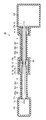
- FIG. 2 is a schematic cross-sectional view illustrating the configuration of the fluid conveyance device 20 according to the first embodiment.
- FIG. 2 illustrates a fluid transfer device 20 that includes a pipe 2 (that is, a first pipe 2a and a second pipe 2b) that connects the vaporizer 101 and the reaction chamber 102.
- the fluid conveyance device 20 conveys the gaseous raw materials 1 a and 1 b supplied from the liquid raw material supply device 110 and vaporized by the vaporizer 101 in the direction from the vaporizer 101 to the reaction chamber 102.
- the first pipe 2 a connects the vaporizer 101 and the joint 13.
- the outer periphery of the first pipe 2a is covered with the first outer pipe 3a.
- the first outer pipe 3a is disposed on the outer periphery of the first pipe 2a.
- the first outer tube 3a has a hollow tube shape, and is formed so that the diameter of the inner peripheral surface of the hollow portion is larger than the diameter of the outer peripheral surface of the first pipe 2a.
- the first pipe 2a and the first outer pipe 3a form a double pipe structure.
- An end plate 17a is provided at one end of the first outer pipe 3a on the joint 13 side in the extending direction of the first pipe 2a.
- An end plate 17c is provided at the other end of the first outer pipe 3a on the vaporizer 101 side in the extending direction of the first pipe 2a.
- a first space 22a surrounded by the first pipe 2a, the first outer pipe 3a, and the end plates 17a and 17c is formed.
- the first space 22a is formed between the first pipe 2a and the first outer pipe 3a.
- the second pipe 2 b connects the joint 13 and the reaction chamber 102.
- the outer periphery of the second pipe 2b is covered with the second outer pipe 3b.
- the second outer pipe 3b is disposed on the outer periphery of the second pipe 2b.
- the second outer tube 3b has a hollow tube shape, and is formed such that the diameter of the inner peripheral surface of the hollow portion is larger than the diameter of the outer peripheral surface of the second pipe 2b.
- the second pipe 2b and the second outer pipe 3b form a double pipe structure.
- An end plate 17b is provided at one end of the second outer pipe 3b on the joint 13 side in the extending direction of the second pipe 2b.
- An end plate 17d is provided at the other end of the second outer pipe 3b on the reaction chamber 102 side in the extending direction of the second pipe 2b.
- a second space 22b surrounded by the second pipe 2b, the second outer pipe 3b, and the end plates 17b and 17d is formed.
- the second space 22b is formed between the second pipe 2b and the second outer pipe 3b.
- heating means having a heat transfer block 8a and a heating unit 9a is disposed.
- the heat transfer block 8a is formed using a material having good thermal conductivity, typified by a metal material such as aluminum or copper. If the heat transfer block 8a is made of aluminum, the heat transfer block 8a can be reduced in weight, and heat transfer efficiency by radiation can be improved by alumite treatment described later, which is desirable. In addition, it is desirable that the heat transfer block 8a be made of copper because the heat conductivity can be further increased.
- Any heating source can be used as the heating unit 9a. Typically, for example, an electric heater, a heating medium circulation heater, an induction heating heater, or the like can be applied to the heating unit 9a.
- the heat transfer block 8a covers the joint 13, the end plate 17a disposed at the joint 13 side end of the first outer tube 3a, and the end plate 17b disposed at the joint 13 side end of the second outer tube 3b.
- the joint 13 is included.
- the heat transfer block 8a can be configured to have a plurality of semi-cylindrical members and to form a hollow cylindrical shape by combining the plurality of members.
- the heating unit 9a is disposed in contact with the outer peripheral side of the heat transfer block 8a.
- the heating unit 9a is in thermal contact with the heat transfer block 8a.
- the heat transfer block 8a is in thermal contact with the end of the first outer tube 3a on the end plate 17a side.
- another heating means that is in thermal contact with the end portion of the second outer tube on the end plate 17d side is provided.
- the heat transfer block 8 and the heating unit 9 shown in FIG. 2 are included.
- the entire apparatus from the vaporizer 101 to the reaction chamber 102 through the first pipe 2a, the heating means and the second pipe 2b is covered with the heat insulating material 21 from the outside.
- Heat transfer between the fluid transfer device 20 and the outside is suppressed by the heat insulating material 21, and re-liquefaction and thermal decomposition of the gaseous raw materials 1 a and 1 b flowing from the vaporizer 101 to the reaction chamber 102 can be suppressed, and energy loss can be suppressed. It can be reduced.
- the heat insulating material 21 may be anything as long as it has a low thermal conductivity that acts as a barrier to suppress heat conduction. For example, a large amount of gas bubbles are contained in a solid such as glass wool or polystyrene foam. It is formed with the material which has.
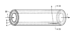
- FIG. 3 is a perspective view showing the configuration of the heat pipe.
- FIG. 4 is a view showing a cross section of the heat pipe taken along line IV-IV shown in FIG.
- the outer pipe 3 is provided outside the pipe 2, and the pipe 2 is inserted into the hollow space in the outer pipe 3.
- a tube structure is formed.
- the outer tube 3 is made of a metal material such as copper, aluminum, and stainless steel.
- a wick 4 formed of a porous material having a capillary force is provided on the inner surface of the outer tube 3.
- a wire mesh or a sintered metal may be attached to the inner surface of the outer tube 3, and fine grooves may be formed on the inner surface of the outer tube 3.
- a space 22 is formed between the outer peripheral surface of the pipe 2 and the inner peripheral surface of the outer tube 3.
- the interior of the space 22 is a hermetically sealed space, which is formed as a vacuum space that has been vacuum depressurized.
- An appropriate amount of the liquid working fluid 5 is injected into the space 22.
- the working fluid 5 injected into the space 22 has a property (condensability) of being heated and evaporated and radiating and condensing.
- a heat pipe structure can be provided between the pipe 2 and the outer pipe 3 in which the working fluid 5 having condensability is enclosed in a vacuum-depressurized sealed space.
- FIG. 5 is a schematic diagram showing the operating principle of the heat pipe.
- a part of the heat pipe structure shown in FIGS. 3 and 4 is disposed in the high temperature part 23 having a relatively high ambient temperature, and the other part is disposed in the low temperature part 24 having a relatively low ambient temperature.
- the high temperature part 23 is heated by the heating part 9 a and has a higher temperature than the low temperature part 24.
- the outer tube 3 is heated by transferring heat from the surroundings in the high temperature portion 23. Therefore, the working fluid 5 sealed between the pipe 2 and the outer tube 3 is also heated and absorbs heat as latent heat, and the working fluid 5 evaporates into a gaseous state.
- the part including the joint 13 in the transport path is heated, and the high temperature part 23 is formed.
- the heat transfer block 8a is heated by the heating unit 9a, the heat from the heating unit 9a is transferred from the outer periphery to the inner periphery of the heat transfer block 8a, and heats the first outer tube 3a.
- the end near the end plate 17a of the first outer tube 3a that is in thermal contact with the heat transfer block 8a is heated from the heating portion 9a to become high temperature, and is enclosed in the first space 22a and filled in the wick 4.
- the liquid working fluid 5 is heated while taking heat of evaporation from the first outer tube 3a, and the working fluid 5 is vaporized.
- the vapor of the evaporated working fluid 5 moves in the flow space 22 from the high-temperature part 23 side to the low-temperature part 24 side as shown by a white arrow 6 in FIG. 6 is carried as steam in the flowing direction.
- the vapor of the working fluid 5 is condensed by releasing latent heat on the outer surface of the pipe 2 and the inner surface of the outer pipe 3 to heat the pipe 2 to a uniform temperature over the entire length thereof.
- the liquid-phase working fluid 5 condensed on the surface of the pipe on the low temperature part 24 side drops on the inner surface of the outer tube 3, penetrates the wick 4, and as shown in the liquid flow 7, by the capillary force of the wick 4. It refluxs to the original high temperature part 23 side.
- the temperature of the pipe 2 is equalized by heat transport by vaporization and liquefaction of the working fluid 5 filled between the pipe 2 and the outer pipe 3.
- the temperature uniformity of the gaseous raw material 1 can be improved over the entire length of the pipe 2, and the temperature of the raw material 1 flowing in the pipe 2 can be maintained at a constant temperature.
- the liquid working fluid 5 condensed on the surface of the pipe 2 can be returned to any position on the inner surface of the outer tube 3 by the capillary action of the wick 4 attached to the inner surface of the outer tube 3.
- the position of the heating means may be provided at an arbitrary position of the outer tube 3. In other words, by heating only a part of the outer tube 3, it is possible to achieve the uniform temperature of the entire pipe 2, so that it is easy and highly accurate without winding a heater such as a tape heater over the entire length of the pipe 2. Temperature management can be realized.
- the number of rewinding portions of the heater may be minimized even when the heater is disconnected (only the heat transfer block 8a portion in this embodiment), maintenance can be performed in a short time, and the downtime of the fluid conveyance device 20 Can be minimized.
- FIG. 6 is an enlarged schematic sectional view showing the vicinity of the heating means having the heat transfer block 8a and the heating section 9a.
- the heat transfer block 8a is arranged so as to surround the first outer tube 3a, the joint 13, and the second outer tube 3b.
- the first pipe 2a and the second pipe 2b are connected with a joint 13 interposed.
- the interior of the heat transfer block 8a is hollow and a space 25 is formed.
- the joint 13 is disposed inside the space 25, and the joint 13 is in a non-contact state with respect to the heat transfer block 8a.
- the heat transfer block 8a heated by the heat transmitted from the heating unit 9a has the first pipe 2a and the first pipe 2a disposed in the joint 13 and the space 25 by heat conduction through the air in the space 25 and radiant heat transfer.
- the two pipes 2b are heated.
- the joint 13 connecting the first pipe 2a and the second pipe 2b is covered with the heat transfer block 8a, and the temperature of the joint 13 is accurately controlled by heating the joint 13 with the heat transfer block 8a interposed. Can do. Therefore, the first pipe 2a heated by the heat pipe formed in the first space 22a and the second pipe 2b heated by the heat pipe formed in the second space 22b are comparable. It becomes easy to maintain the joint 13 at temperature.
- the heat transfer block 8a covering the joint 13 having a shape projecting radially outward with respect to the first pipe 2a and the second pipe 2b can be formed, for example, as an integral part of a metal material. High-precision temperature control can be performed.
- a gap is provided between the heat transfer block 8 a and the joint 13.
- the gap is provided as a gap that keeps the heat transfer block 8a and the joint 13 in non-contact and does not cause convection of air interposed between the heat transfer block 8a and the joint 13.
- the heat transfer block 8a can be formed in accordance with the shape of the joint 13 such that a gap of about several millimeters is formed between the inner peripheral surface of the heat transfer block 8a and the outer peripheral surface of the joint 13. .
- the heat transfer from the heat transfer block 8a to the joint 13 is not convective heat transfer via air, but heat transfer by heat conduction and radiation, thereby suppressing temperature unevenness due to air convection. be able to. Therefore, the joint 13 can be heated more uniformly, and more accurate temperature control is possible.
- the inner peripheral surface of the heat transfer block 8a facing the joint 13 may be subjected to a radiation rate improving process.
- a radiation rate improving process For example, alumite treatment that forms microscopic depressions on the inner peripheral surface of the hollow heat transfer block 8a, or blackening treatment that coats the inner peripheral surface of the heat transfer block 8a so as to become a black body. Can be performed. If it does in this way, since heat transfer efficiency by radiation from heat transfer block 8a to joint 13 can be improved, it will become possible to heat joint 13 more efficiently.
- the outer peripheral surface 3c of the first outer tube 3a covering the outer peripheral portion of the first pipe 2a is in contact with the inner surface of the heat transfer block 8a, and the heat generated in the heating unit 9a is conducted through the heat transfer block 8a. Therefore, it can be directly transmitted to the first outer tube 3a.
- a gap 25a is formed between the outer peripheral surface 3d of the second outer pipe 3b covering the outer peripheral portion of the second pipe 2b and the heat transfer block 8a. In the portion where the heat transfer block 8a extends so as to face the outer peripheral surface 3d of the second outer tube 3b, the heat transfer block 8a and the second outer tube 3b are arranged with a slight gap 25a.
- the heat transfer block 8a can be prevented from interfering with the second outer tube 3b. That is, the heat pipe formed in the second space 22b inside the second outer tube 3b is heated by the heating unit 9 (see FIG. 2), but when the heat transfer block 8a comes into contact with the second outer tube 3b. The problem of disturbing the temperature control of the heating unit 9 arises.
- the gap 25a and suppressing the occurrence of contact between the heat transfer block 8a and the second outer tube 3b the accuracy of temperature control of the heat pipe in the second space 22b can be improved.
- the arrangement of the second outer tube 3b is not restricted by the heat transfer block 8a, and the heating unit 9 and the second outer tube 3b that directly heats the second outer tube 3b. Concentricity can be ensured. Therefore, the heat contact state between the heat transfer block 8 (see FIG. 2) for transferring the heat generated in the heating unit 9 to the second outer tube 3b and the second outer tube 3b can be kept good.
- the gap 25a is covered and closed by a heat insulating material 21 that covers each part of the fluid conveyance device 20 from the outside.
- a heat insulating material 21 that covers each part of the fluid conveyance device 20 from the outside.
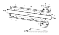
- FIG. 7 is a schematic cross-sectional view showing the arrangement of the heating means for heating the heat pipe when the pipe 2 is inclined with respect to the horizontal plane.
- the heat pipe is advantageously operated in a bottom heat mode in which heat is transferred from bottom to top. That is, the action of gravity greatly affects the return of the liquid working fluid 5 to the high temperature portion 23 side. Therefore, when the high temperature part 23 is installed below (bottom heat mode), the maximum heat transport amount is most improved.
- the high temperature part 23 is turned up (top heat mode)
- the heating unit 9 is disposed on the lower side (that is, the right side in FIG. 7) in the arrangement of the pipe 2. And a heating means having a heat transfer block 8 can be arranged. If it does in this way, since the heat pipe formed in the space 22 can be made into bottom heat mode, the performance of a heat pipe can be improved and the piping 2 by a heat pipe can be heated more efficiently.
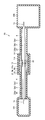
- FIG. 8 is a schematic cross-sectional view illustrating the configuration of the fluid conveyance device 20 according to the second embodiment.
- the fluid conveyance device 20 in the second embodiment is arranged inside the heat transfer block 8a along the direction in which the first piping 2a and the second piping 2b extend. The difference is that an extended heat pipe 15 is provided.
- the heating unit 9 a that heats the heat transfer block 8 a from the outer peripheral side may cause temperature unevenness in the extending direction of the pipe 2.
- the temperature distribution of the heat transfer block 8a may be generated in the extending direction of the pipe 2 due to the temperature unevenness of the tape heater or the tape heater itself.
- the temperature of the heat pipe 15 is extended by extending the pipe 2 by heating the heat pipe 15 provided inside the heat transfer block 8a along the extending direction of the pipe 2 using the heating unit 9a as a heat source.
- Uniform in direction That is, since the uniformity of the temperature of the heat transfer block 8a in the extending direction of the pipe 2 can be improved by the configuration of the fluid conveyance device 20 of the second embodiment, the joint heated through the heat transfer block 8a The temperature uniformity of 13 can be further improved. Since the other configuration of the fluid conveyance device 20 is as described in the first embodiment, the description thereof will not be repeated.
- FIG. 9 is a schematic cross-sectional view illustrating the configuration of the fluid conveyance device 20 according to the third embodiment.
- the first outer tube 3a and the second outer tube 3b are both in thermal contact with the heat transfer block 8b as compared with the fluid conveyance device 20 in the first embodiment. Is different.
- the joint 13 side of the first outer pipe 3 a provided with the end plate 17 a is centered on the joint 13 connecting the first pipe 2 a and the second pipe 2 b.
- the outer peripheral surface 3c at one end and the outer peripheral surface 3d at one end on the joint 13 side of the second outer tube 3b provided with the end plate 17b are in contact with the inner peripheral surface of the heat transfer block 8b, respectively.
- a heat transfer block 8b is formed.
- the pipe 2 connecting the vaporizer 101 and the reaction chamber 102 can be heated by one heating unit 9b. That is, the heat generated in the heating unit 9b is transmitted to the heat transfer block 8b, and heat pipes formed in the first space 22a and the second space 22b are heated by the heat transfer block 8b, and the periphery of the joint 13 Is heated. Therefore, since the whole fluid conveyance apparatus 20 can be heated using one heating part 9b, temperature control of heating becomes easier and temperature uniformity can be further improved. In addition, since the number of heating units can be reduced as compared with the fluid conveyance device 20 of the first embodiment including the plurality of heating units 9 and 9a, the cost of the fluid conveyance device 20 can be reduced. it can.
- the performance of the heat pipe may be deteriorated.
- the pipe 2 of the fluid conveyance device 20 of the third embodiment shown in FIG. 9 is inclined with respect to the horizontal plane, either the heat pipe that heats the first pipe 2a or the heat pipe that heats the second pipe 2b Will be placed in the top heat mode.
- the fluid conveyance device 20 of the third embodiment is desirably applied when the pipe 2 is arranged substantially horizontally.
- first outer tube 3a and the second outer tube 3b need to be accurately centered (centered).
- accurate centering it is necessary to eliminate errors such as processing accuracy and assembly accuracy, and the manufacturing cost increases. Therefore, accurate centering is often difficult.
- heat transfer grease can be filled between the outer peripheral surface 3c of the first outer tube 3a and the outer peripheral surface 3d of the second outer tube 3b and the heat transfer block 8b. If it does in this way, since the accuracy error of the 1st outer tube 3a and the 2nd outer tube 3b can be permitted, manufacturing cost can be reduced, and the 1st outer tube 3a and the 2nd outer tube 3b are made into a heat transfer block. The effect that the heat pipe formed in the space 22 can be efficiently heated and brought into thermal contact with 8b can be obtained similarly.
- FIG. 10 is a schematic cross-sectional view illustrating a configuration of a modification of the fluid conveyance device 20 according to the third embodiment.
- the heat pipe 15 is provided inside the heat transfer block 8c. If it does in this way, since the uniformity of the temperature of the heat transfer block 8c in the extending direction of the pipe 2 can be improved, the first pipe 2a and the second pipe 2b heated through the heat transfer block 8c can be improved. The temperature uniformity can be further improved, and the temperature uniformity of the joint 13 can be further improved.
- FIG. 11 is a schematic cross-sectional view illustrating the configuration of the fluid conveyance device 20 according to the fourth embodiment.
- the fluid transfer device 20 in the fourth embodiment is formed by bending a connecting portion that connects the first pipe 2a and the second pipe 2b instead of the joint 13.
- the difference is that it has an elbow 16.
- an L-shaped space 25 bent by 90 ° is formed inside the heat transfer block 8d.
- the first pipe 2a is inserted into the heat transfer block 8d from one side of the L-shaped space 25, and the second pipe 2b is inserted into the heat transfer block 8d from the other side of the space 25.
- An elbow 16 is disposed inside the space 25.
- a through hole having a diameter corresponding to the inner diameter of the first pipe 2a and the second pipe 2b is formed in the elbow 16, and the through hole is formed to be bent at 90 °.
- the first pipe 2a and the second pipe 2b are connected with an elbow 16 interposed.
- the elbow 16 has a function as a connecting portion that connects the first pipe 2a and the second pipe 2b.
- the elbow 16 formed to be bent is heated by winding a tape heater around the outer periphery, it is difficult to make the winding method of the tape heater uniform between the inner peripheral side and the outer peripheral side of the bent portion. It is difficult to heat 16 uniformly. Further, if the outer periphery of the elbow 16 is covered with a heat pipe, it is necessary to provide a heat pipe having a complicated shape, which causes an increase in cost and a decrease in the reliability of the heat pipe. On the other hand, as shown in FIG. 11, the heat transfer block 8d covering the elbow 16 is configured to transmit heat to the elbow 16 by heat conduction and radiation via air, so that the temperature of the elbow 16 can be accurately adjusted. Can be managed. Therefore, the elbow 16 can be uniformly heated by an inexpensive device.
- FIG. 12 is a schematic cross-sectional view illustrating a configuration of a modification of the fluid conveyance device 20 according to the fourth embodiment.
- the heat pipe 15 is provided inside the heat transfer block 8e.
- the temperature uniformity of the elbow 16 can be further improved.
- the heating unit 9e heats a part of the heat pipe 15, the entire heat pipe 15 is heated uniformly.
- the heating unit 9d is provided on the right side of the heat transfer block 8d, whereas in the modification shown in FIG. 12, only the upper and lower sides of the heat transfer block 8e in the figure.
- a heating unit 9e is provided, and no heating unit is provided on the right side of the heat transfer block 8e. Therefore, part of the heating unit 9e can be omitted, and the manufacturing cost reduction and the reliability improvement of the fluid conveyance device 20 can be achieved.
- two pipes of the first pipe 2a and the second pipe 2b are provided between the vaporizer 101 and the reaction chamber 102, and the first pipe 2a and the second pipe are provided.
- the example in which 2b is combined using the joint 13 or the elbow 16 has been described.
- the fluid conveyance device of the present invention is not limited to this configuration, and a plurality of arbitrary pipes may be appropriately connected to pipe joints (in addition to the straight joint 13 and the bent elbow 16, other joints such as a trifurcated joint and cheese). Can also be applied to those connected through the interposition.
- the structure is not limited to a structure in which a plurality of pipes are connected by pipe joints, and a plurality of pipes may be connected through an arbitrary valve. Even in the case of piping connected by a valve, a space is formed inside the heat transfer block, and a slight gap is provided between the heat transfer block and the valve is installed by the heat transfer block. If the configuration covers the outer periphery, the valve can be uniformly and efficiently heated as in the first to fourth embodiments.
- heating of a pipe using a heat pipe has been described.
- a cooler that actively takes heat from the heat pipe and cools the working fluid of the heat pipe is connected to the heat pipe and the heat pipe. You may provide so that it may contact.
- any cooler such as a water cooling circuit or a Peltier element can be applied.
- the entire heat pipe can be efficiently cooled by cooling a part of the heat pipe. That is, it is not necessary to cool the entire heat pipe by the heat transport operation of the heat pipe described in the first embodiment, and the heat pipe can be efficiently cooled. In this way, when it is desired to lower the temperature of the pipe during maintenance, etc., the pipe can be lowered at a uniform temperature at a higher speed, so the time required to lower the temperature of the pipe can be shortened and the maintenance time can be shortened. Can do.
- the fluid conveyance device of the present invention is particularly suitable for a fluid conveyance device that conveys a substance that requires high-precision temperature management, such as a reaction gas when a film formation target is formed on a semiconductor wafer, a liquid crystal glass substrate, or the like. It can be advantageously applied.
Landscapes
- Chemical & Material Sciences (AREA)
- Engineering & Computer Science (AREA)
- General Engineering & Computer Science (AREA)
- Mechanical Engineering (AREA)
- General Chemical & Material Sciences (AREA)
- Chemical Kinetics & Catalysis (AREA)
- Materials Engineering (AREA)
- Metallurgy (AREA)
- Organic Chemistry (AREA)
- Chemical Vapour Deposition (AREA)
Abstract
配管の全体を高精度に温度管理できる流体搬送装置(20)を提供する。流体搬送装置(20)は、第一配管(2a)および第二配管(2b)を連結する連結部(13)と、第一配管(2a)の外周部を覆う第一外管(3a)と、第二配管(2b)の外周部を覆う第二外管(3b)と、連結部(13)、第一外管(3a)および第二外管(3b)の連結部(13)側の端部(17a,17b)を覆う伝熱ブロック(8a)と、伝熱ブロック(8a)に熱的に接触する加熱部(9a)を備える。第一配管(2a)および第一外管(3a)の間には第一空間(22a)が形成され、第二配管(2b)および第二外管(3b)の間には第二空間(22b)が形成されている。第一空間(22a)および第二空間(22b)は、密閉された真空空間であって、内部に作動流体(5)が封入されている。加熱部(9a)は、作動流体(5)を加熱して気化させる。
Description
本発明は、流体搬送装置に関し、特に、被搬送物である流体に熱を加える流体搬送装置に関する。
従来、流体を搬送するための配管において、配管内部を輸送される流体の高精度の温度管理を必要とするとき、配管を加熱することにより流体の温度を制御する場合がある。たとえば成膜装置において、液体状の原料を気化させる気化器と、気化された気体状の原料を基板に供給して基板の表面に成膜を行なう反応室とを連結する配管では、配管内部での反応ガスの再液化や熱分解を防止して反応室へ原料を安定して供給するために、たとえばテープヒータなどを配管に巻き、配管を加熱する(たとえば、特開2001-44186号公報(特許文献1)参照)。
図13は、従来の成膜装置の構成を示すブロック図である。図14は、図13に示す成膜装置に用いられる配管装置の構成を示す模式図である。図13に示すように、従来の成膜装置は、外部より供給された液体状の原料1を加熱し気化させて気体状にする気化器201と、気体状の原料が供給されて、基板の表面への成膜などの所定の反応が行なわれる、反応室202とを備える。また成膜装置は、気化器201において気化された原料を反応室202へ向けて搬送するキャリアガスを気化器201へ供給する、キャリアガス供給装置205を備える。
気化器201と反応室202とは配管203により連結されている。図14に示すように、配管203には、気化器201で気化したガスの再液化や熱分解の防止のために、配管203を加熱するテープヒータ204が配管203の外周面に巻かれて、温度制御が行なわれる。
配管203の全長を均一の温度に制御するためには、配管203の外周面に均等にテープヒータ204を巻く必要がある。しかし、テープヒータ204の巻き方やテープヒータ204自身の発熱時の温度ムラにより、配管203の温度のバラつきが発生することがある。また、テープヒータ204の一部が断線すると、断線したテープヒータ204を除去して、新たにテープヒータ204を巻き直す必要がある。しかしながら、テープヒータ204の巻き直しに時間がかかると共に、巻き直す前と同じテープヒータ204の巻き方を再現することは困難である。そのため、加熱時の配管203の温度分布がテープヒータ204断線前の状態から変化し、成膜の性能に影響を及ぼすという問題があった。
そのため従来、配管の外壁をヒートパイプにより被覆して、配管の温度を所定の温度に均一性良く保持し、配管の全長にヒータを巻くことなく配管全体を高精度に温度管理する技術が提案されている(たとえば、特開平6-168877号公報(特許文献2)参照)。
特開2001-44186号公報
特開平6-168877号公報
しかしながら、流体を搬送するための配管系全体をヒートパイプで被覆して加熱する場合、ヒートパイプに封入される作動流体を加熱するための熱源およびヒートパイプの加熱部を配管系とは別に設ける必要がある。また、配管系を加熱して凝縮した液を集約してもとの加熱部に還流させるための機構が必要である。そのため、装置構成が複雑となり、装置が大型化し、製造コストが増大するという問題があった。
また、配管の外周を被覆するヒートパイプの放熱部(凝縮部)は、継ぎ手およびバルブの周囲を含めて継ぎ手およびバルブの形状に合わせて被覆する必要がある。そのため、配管系を覆うヒートパイプの形状が極めて複雑になり、所要のヒートパイプ放熱部を形成するための製作コストが極めて高くなるとともに、形状の複雑さによりヒートパイプの信頼性低下を招くので、実現性に欠けるという問題点があった。
本発明は上記の問題に鑑みてなされたものであり、その主たる目的は、配管の全長にヒータを巻くことなく、配管の全体を高精度に温度管理できる、流体搬送装置を提供することである。
本発明に係る流体搬送装置は、第一配管と、第二配管と、第一配管および第二配管を連結する連結部と、第一配管の外周部を覆う第一外管と、第二配管の外周部を覆う第二外管と、連結部、第一外管の連結部側の端部および第二外管の連結部側の端部を覆う伝熱ブロックと、伝熱ブロックに熱的に接触する加熱部を備える。第一配管および第一外管の間には、第一空間が形成されている。第二配管および第二外管の間には、第二空間が形成されている。第一空間および第二空間は、密閉された真空空間であって、内部に作動流体が封入されている。加熱部は、作動流体を加熱して気化させる。
ここで、「熱的に接触」とは、二つの部材間(この場合伝熱ブロックと加熱部との間)において熱が直接的に伝達される、熱伝達効率が十分に高い状態とされていることをいい、二部材が互いに当接して直接機械的に接触している場合に限られない。たとえば、加熱部を伝熱ブロックに内蔵する構成など、二部材が互いに一体化されている場合、また、熱伝導性に優れた物質を中間に介在させ間接的に二部材が接触している場合をも、熱的に接触している状態に含むものとする。
上記流体搬送装置において好ましくは、第二外管の外周面と、伝熱ブロックとの間には隙間が形成されている。流体搬送装置は、隙間を覆う断熱材をさらに備える。
上記流体搬送装置において好ましくは、伝熱ブロックは、第一外管の外周面および第二外管の外周面に熱的に接触する。
上記流体搬送装置において好ましくは、伝熱ブロックの内部に、第一配管または第二配管の延びる方向に沿って延在するヒートパイプを有する。
上記流体搬送装置において好ましくは、連結部は、屈曲形成されたエルボを有する。
本発明の流体搬送装置によると、第一空間および第二空間をヒートパイプ化し、このヒートパイプを加熱する加熱部と熱的に接触する伝熱ブロックが、第一配管と第二配管との連結部を覆うように配置される。したがって、気体状の材料の通過する第一配管および第二配管の連結部側の端部ならびに連結部を含めた、配管系の全長に亘る温度の均一性を向上させることができる。
1,1a,1b 原料、2 配管、2a 第一配管、2b 第二配管、3 外管、3a 第一外管、3b 第二外管、3c,3d 外周面、4 ウィック、5 作動流体、6 蒸気流、7 液流、8,8a~8e 伝熱ブロック、9,9a~9e 加熱部、10 熱流、13 継手、15 ヒートパイプ、16 エルボ、17a~17d 端板、20 流体搬送装置、21 断熱材、22 空間、22a 第一空間、22b 第二空間、23 高温部、24 低温部、25 空間、25a 隙間、101 気化器、102 反応室。
以下、図面に基づいてこの発明の実施の形態を説明する。なお、以下の図面において、同一または相当する部分には同一の参照番号を付し、その説明は繰返さない。
なお、以下に説明する実施の形態において、各々の構成要素は、特に記載がある場合を除き、本発明にとって必ずしも必須のものではない。また、以下の実施の形態において、個数、量などに言及する場合、特に記載がある場合を除き、上記個数などは例示であり、本発明の範囲は必ずしもその個数、量などに限定されない。
(実施の形態1)
図1は、本発明に係る流体搬送装置を備える、反応室へ気体状の物質を供給するための物質供給システムの概略構成を示すブロック図である。図1に示す物質供給システムは、外部より液体状の原料を受け入れて気化器101に供給する液状原料供給装置110と、液状原料供給装置110より供給された液体状の原料を加熱し気化させて気体状にする気化器101と、気体状の原料が供給されて、基板の表面への成膜などの所定の反応が行なわれる、反応室102とを備える。また物質供給システムは、気化器101において気化された原料を反応室102へ向けて搬送するキャリアガスを気化器101へ供給する、キャリアガス供給装置120を備える。
図1は、本発明に係る流体搬送装置を備える、反応室へ気体状の物質を供給するための物質供給システムの概略構成を示すブロック図である。図1に示す物質供給システムは、外部より液体状の原料を受け入れて気化器101に供給する液状原料供給装置110と、液状原料供給装置110より供給された液体状の原料を加熱し気化させて気体状にする気化器101と、気体状の原料が供給されて、基板の表面への成膜などの所定の反応が行なわれる、反応室102とを備える。また物質供給システムは、気化器101において気化された原料を反応室102へ向けて搬送するキャリアガスを気化器101へ供給する、キャリアガス供給装置120を備える。
液状原料供給装置110と気化器101とは、流体輸送経路111、バルブ112および流体輸送経路114によって連結されている。液状原料供給装置110と気化器101間の流体輸送経路111,114は、バルブ112を介して接合されている。キャリアガス供給装置120と気化器101とは、流体輸送経路121、バルブ122および流体輸送経路124によって連結されている。キャリアガス供給装置120と気化器101間の流体輸送経路121,124は、バルブ122を介して接合されている。気化器101と反応室102とは、流体輸送経路を構成する第一配管2aおよび第二配管2bによって連結されている。第一配管2aおよび第二配管2bは、連結部の一例としての継手13によって連結されている。継手13は、加熱部9によって覆われている。
液状原料供給装置110から供給された液体状の原料は、気化器101において熱を加えられて温度上昇し、沸点に到達することにより気体へと状態変化する。気化器101で気化した気体状の原料(これを反応ガスと称する)は、キャリアガス供給装置120から供給されるキャリアガスによって、第一配管2a、継手13および第二配管2bを経由して、反応ガスとして反応室102に供給される。
物質供給システムはまた、制御部130を備える。液状原料供給装置110から気化器101への原料の供給量は、液状原料供給装置110と気化器101とを連結する流体輸送経路111,114の間のバルブ112の開度を制御部130にて制御することにより、制御される。キャリアガスの流量は、キャリアガス供給装置120と気化器101を連結する流体輸送経路121,124の間のバルブ122の開度を制御部130にて制御することにより、制御される。
気化器101内部の温度は、気化器101の内部に配置された図示しないヒータなどの加熱部による熱供給量を制御部130にて制御することにより、制御される。反応室102内部の温度も、反応室102の内部に配置された図示しない加熱部による熱供給量を制御部130にて制御することにより、制御される。制御部130が加熱部9に供給される熱量を制御することにより、継手13を通過する反応ガスの温度が制御される。図1に示す点線矢印は、制御部130からの制御信号の経路を示している。
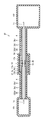
図2は、実施の形態1の流体搬送装置20の構成を示す断面模式図である。図2には、気化器101と反応室102とを連結する配管2(すなわち第一配管2aおよび第二配管2b)を含んで構成される、流体搬送装置20が図示されている。流体搬送装置20は、気化器101から反応室102へ向かう方向に、液状原料供給装置110から供給され気化器101で気化された、気体状の原料1a,1bを搬送する。
第一配管2aは、気化器101と継手13とを連結する。第一配管2aは、第一外管3aによって外周部を覆われている。第一外管3aは、第一配管2aの外周に配置されている。第一外管3aは、中空の管形状であって、その中空部の内周面の径が第一配管2aの外周面の径よりも大きくなるように形成されている。第一配管2aと第一外管3aとは、二重管構造を形成する。
第一配管2aの延在方向における継手13側の第一外管3aの一端部には、端板17aが設けられている。第一配管2aの延在方向における気化器101側の第一外管3aの他端部には、端板17cが設けられている。第一配管2aの外周部において、第一配管2a、第一外管3aおよび端板17a,17cによって囲まれた第一空間22aが形成されている。第一空間22aは、第一配管2aおよび第一外管3aの間に形成されている。
第二配管2bは、継手13と反応室102とを連結する。第二配管2bは、第二外管3bによって外周部を覆われている。第二外管3bは、第二配管2bの外周に配置されている。第二外管3bは、中空の管形状であって、その中空部の内周面の径が第二配管2bの外周面の径よりも大きくなるように形成されている。第二配管2bと第二外管3bとは、二重管構造を形成する。
第二配管2bの延在方向における継手13側の第二外管3bの一端部には、端板17bが設けられている。第二配管2bの延在方向における反応室102側の第二外管3bの他端部には、端板17dが設けられている。第二配管2bの外周部において、第二配管2b、第二外管3bおよび端板17b,17dによって囲まれた第二空間22bが形成されている。第二空間22bは、第二配管2bおよび第二外管3bの間に形成されている。
継手13の周囲には、伝熱ブロック8aおよび加熱部9aを有する加熱手段が配設されている。伝熱ブロック8aは、アルミニウムまたは銅などの金属材料に代表される、熱伝導性の良好な材料を用いて形成されている。伝熱ブロック8aをアルミニウム製とすると、伝熱ブロック8aを軽量化でき、また後述するアルマイト処理により輻射による熱伝達効率を向上できるので望ましい。また伝熱ブロック8aを銅製とすると、熱伝導率をより高くできるので望ましい。加熱部9aとしては、任意の熱源を用いることができる。典型的には、たとえば電気ヒータ、熱媒循環式のヒータまたは誘導加熱式のヒータなどを、加熱部9aに適用することができる。
伝熱ブロック8aは、継手13、第一外管3aの継手13側の端部に配置された端板17aおよび第二外管3bの継手13側の端部に配置された端板17bを覆い、継手13を内包するように設けられている。たとえば、半円筒型の複数の部材を有し、当該複数の部材を組み合わせることで中空の円筒形状が形成されるように、伝熱ブロック8aを構成することができる。
加熱部9aは、伝熱ブロック8aの外周側に接触して配置されている。加熱部9aは、伝熱ブロック8aに熱的に接触する。伝熱ブロック8aは、第一外管3aの端板17a側の端部に熱的に接触する。伝熱ブロック8aおよび加熱部9aを含む加熱手段とは別に、第二外管の端板17d側の端部に熱的に接触する他の加熱手段が設けられており、当該他の加熱手段は図2に示す伝熱ブロック8および加熱部9を含む。
気化器101から第一配管2a、加熱手段および第二配管2bを経て反応室102に至る装置全体が、断熱材21によって外側から被覆されている。断熱材21によって、流体搬送装置20と外部との熱伝達が抑制されており、気化器101から反応室102へ流れる気体状の原料1a,1bの再液化や熱分解を抑制できるとともに、エネルギーロスを低減できる構成とされている。断熱材21は、熱伝導を抑える障壁の働きをする熱伝導性の低いものであればどのようなものであってもよく、たとえばグラスウールやポリスチレンフォームなどの固体の中に気体の小泡を多量に有する素材により形成される。
第一空間22aおよび第二空間22bに形成されたヒートパイプの構成について詳細に説明する。図3は、ヒートパイプの構成を示す斜視図である。図4は、図3に示すIV-IV線に沿うヒートパイプの断面を示す図である。
本実施の形態の流体搬送装置20では、図3および図4に示すように、配管2の外部に外管3を設け、外管3内の中空空間内に配管2が挿通された、二重管構造が形成されている。外管3は、たとえば銅、アルミニウム、ステンレスなどの金属材料により形成されている。外管3の内面には、毛管力を有する多孔質材料により形成されたウィック4が設けられている。ウィック4としては、外管3の内表面に金網や焼結金属が取り付けられてもよく、外管3の内表面に細かい溝が形成されてもよい。
配管2の外周面と、外管3の内周面との間には、空間22が形成されている。空間22の内部は、密閉された空間であって、真空減圧された真空空間として形成されている。この空間22の内部に、液体状の作動流体5を適量注入する。空間22に注入された作動流体5は、加熱されて蒸発し、かつ放熱して凝縮する性質(凝縮性)を有する。このようにして、配管2と外管3との間に、真空減圧された密閉空間中に凝縮性を有する作動流体5が封入された、ヒートパイプ構造を設けることができる。
図5は、ヒートパイプの動作原理を示す模式図である。図3および図4に示すヒートパイプ構造の一部を、周囲の温度が相対的に高い高温部23に配置し、他の一部を周囲の温度が相対的に低い低温部24に配置する。高温部23は、加熱部9aにより加熱されており、低温部24に対して温度が高くなっている。熱流10に示すように、高温部23において周囲から伝熱されることにより、外管3が加熱される。そのため、配管2と外管3との間に封入された作動流体5も加熱され、潜熱として熱を吸収して作動流体5は蒸発して気体状になる。
図2に示す本実施の形態の流体搬送装置20において、具体的には、加熱部9aが伝熱ブロック8aに外周側から熱を加えることにより、気化器101と反応室102とを連結する流体輸送経路における継手13を含む箇所が加熱され、高温部23が形成される。加熱部9aで伝熱ブロック8aを加熱すると、加熱部9aからの熱は伝熱ブロック8aの外周から内周に伝わり、第一外管3aを加熱する。伝熱ブロック8aに熱接触している第一外管3aの端板17a近傍の端部が加熱部9aから伝熱されて高温になり、第一空間22a内に封入されウィック4に満たされている液体状の作動流体5は第一外管3aから蒸発熱を奪いながら加熱されて、作動流体5が蒸気化する。
蒸発した作動流体5の蒸気が、図5中に白抜き矢印で示す蒸気流6のように、高温部23側から低温部24側へ流れ空間22の内部を移動することにより、熱が蒸気流6の流れる方向に蒸気として運ばれる。このとき作動流体5の蒸気は、配管2の外表面および外管3の内表面で潜熱を放出することで凝縮して、配管2をその全長にわたり均一温度に加熱する。低温部24側の配管の表面で凝縮した液相の作動流体5は、外管3の内表面に滴下し、ウィック4に浸透して、液流7に示すように、ウィック4の毛管力によってもとの高温部23側へ還流する。
このように、配管2と外管3との間に充填されている作動流体5の蒸気化および液化による熱輸送で、配管2の温度の均熱化を行なう。このようにして、配管2の全長に亘って気体状の原料1の温度の均一性を向上させ、配管2内を流れる原料1の温度を一定温度に維持することができる。
また、外管3の内面に装着されているウィック4の毛管作用により、配管2の表面で凝縮した液体状の作動流体5を外管3の内面の任意の位置に還流させることができるので、加熱手段の位置は外管3の任意の位置に設けられていても構わない。つまり、外管3の一部分のみを加熱することで、配管2全体の均熱化を実現することができるので、配管2の全長に亘りテープヒータなどのヒータを巻かなくても容易に高精度の温度管理を実現することができる。加えて、ヒータの断線時にもヒータの巻き直し箇所が最小限でよい(本実施の形態では伝熱ブロック8aの部分のみ)ので、短時間でメンテナンスすることができ、流体搬送装置20のダウンタイムを最小限に抑えることができる。
次に、流体搬送装置20の加熱手段周辺の構成について詳細に説明する。図6は、伝熱ブロック8aおよび加熱部9aを有する加熱手段周辺を拡大して示す断面模式図である。図6に示すように、伝熱ブロック8aは、第一外管3a、継手13および第二外管3bを取り囲むように配置されている。継手13を介在させて第一配管2aおよび第二配管2bが連結されている。
伝熱ブロック8aの内部は中空に形成され、空間25が形成されている。継手13は空間25の内部に配置されており、継手13は伝熱ブロック8aに対し非接触の状態を保っている。加熱部9aから伝達された熱により加熱された伝熱ブロック8aは、空間25内部の空気を介した熱伝導、および輻射熱伝達によって、継手13ならびに空間25内に配置された第一配管2aおよび第二配管2bを加熱する。
つまり、第一配管2aおよび第二配管2bを連結する継手13を伝熱ブロック8aで覆い、伝熱ブロック8aを介在させて継手13を加熱することにより、継手13の温度を精度よく管理することができる。そのため、第一空間22a内に形成されるヒートパイプにより加熱される第一配管2a、および、第二空間22b内に形成されるヒートパイプにより加熱される第二配管2bに対して、同程度の温度に継手13を維持することが容易に可能となる。第一配管2aおよび第二配管2bに対して径方向外側に張り出す形状の継手13を覆う伝熱ブロック8aは、たとえば金属材料の一体物として形成することができ、安価な装置で継手13の高精度の温度制御を行なうことができる。
伝熱ブロック8aと継手13との間には、隙間が設けられている。この隙間は、伝熱ブロック8aおよび継手13を非接触に保ち、かつ、伝熱ブロック8aと継手13との間に介在する空気の対流が生じない程度の空隙として設けられる。たとえば、伝熱ブロック8aの内周面と継手13の外周面との間に、数ミリメートル程度の隙間が形成されるように、継手13の形状に合わせて伝熱ブロック8aを形成することができる。
このように、伝熱ブロック8aから継手13への熱伝達を、空気を介した対流熱伝達でなく、熱伝導および輻射による熱伝達とすることにより、空気の対流による温度ムラの発生を抑制することができる。そのため、より均一に継手13を加熱することができ、より高精度の温度制御が可能となる。
継手13に対向する伝熱ブロック8aの内周面には、輻射率向上処理を施してもよい。たとえば、中空の伝熱ブロック8aの内周側の表面に微視的なくぼみを形成するアルマイト処理や、伝熱ブロック8aの内周側の表面が黒体となるようにコーティングする黒色化処理などを行なうことができる。このようにすれば、伝熱ブロック8aから継手13への輻射による熱伝達効率を向上することができるので、より効率よく継手13を加熱することが可能となる。
第一配管2aの外周部を覆う第一外管3aの外周面3cは、伝熱ブロック8aの内面と接触しており、加熱部9aで発生した熱が伝熱ブロック8aを経由して熱伝導により直接第一外管3aへ伝達され得る構成とされている。一方、第二配管2bの外周部を覆う第二外管3bの外周面3dと、伝熱ブロック8aとの間には、隙間25aが形成されている。伝熱ブロック8aが第二外管3bの外周面3dに対向するように延伸する部分では、伝熱ブロック8aと第二外管3bとがわずかの隙間25aを設けて配置されている。
このように隙間25aを形成することにより、伝熱ブロック8aが第二外管3bと干渉することを抑制できる。つまり、第二外管3bの内側の第二空間22bに形成されるヒートパイプは、加熱部9(図2参照)により加熱されているが、伝熱ブロック8aが第二外管3bと接触すると、加熱部9の温度制御を乱すという問題が生じる。隙間25aを形成して、伝熱ブロック8aと第二外管3bとの接触の発生を抑制することにより、第二空間22bのヒートパイプの温度制御の精度を向上させることができる。
また、隙間25aを形成することによって、第二外管3bの配置が伝熱ブロック8aにより規制されることがなく、第二外管3bを直接加熱する加熱部9と第二外管3bとの同心度を確保することができる。そのため、加熱部9で発生した熱を第二外管3bに伝達する伝熱ブロック8(図2参照)と、第二外管3bとの熱接触状態を、良好に保つことができる。
隙間25aは、流体搬送装置20を構成する各部を外側から被覆する断熱材21によって覆われて塞がれている。このように隙間25aを塞ぐことにより、外部から空間25へ空気が流入することを防止し、空間25内部における空気の流動が生じないようにすることができる。したがって、伝熱ブロック8aから継手13への、空気を介した熱伝導および輻射による熱伝達をより均一に行なうことができるので、継手13周辺の温度分布の均一性をより向上させることができる。
図7は、配管2が水平面に対し傾斜している場合の、ヒートパイプを加熱する加熱手段の配置を示す断面模式図である。ヒートパイプは一般に、熱を下から上に移動させるボトムヒートモードでの作動が有利とされている。つまり、液体状の作動流体5の高温部23側への還流には、重力の作用が大きく影響する。そのため、高温部23を下方に設置した場合(ボトムヒートモード)で最大熱輸送量が最も向上する。逆に、高温部23を上にした場合(トップヒートモード)では、液体状の作動流体5が重力に逆らって高温部23へ移動する必要があり、ウィック4の毛管力のみにより作動流体5の還流を行なう必要が生じるので、ヒートパイプの性能低下は免れない。
そこで、たとえば図7に示す配管2の延在方向が水平面に対し角度θを形成するように傾斜している場合、配管2の配置における下方側(すなわち図7中の右側)に、加熱部9および伝熱ブロック8を有する加熱手段を配置することができる。このようにすれば、空間22内に形成されるヒートパイプをボトムヒートモードとすることができるので、ヒートパイプの性能を向上させ、ヒートパイプによる配管2の加熱をより効率よく行なうことができる。
(実施の形態2)
図8は、実施の形態2の流体搬送装置20の構成を示す断面模式図である。実施の形態2における流体搬送装置20は、上述した実施の形態1における流体搬送装置20と比較して、伝熱ブロック8aの内部に、第一配管2aおよび第二配管2bの延びる方向に沿って延在するヒートパイプ15が設けられている点が異なる。
図8は、実施の形態2の流体搬送装置20の構成を示す断面模式図である。実施の形態2における流体搬送装置20は、上述した実施の形態1における流体搬送装置20と比較して、伝熱ブロック8aの内部に、第一配管2aおよび第二配管2bの延びる方向に沿って延在するヒートパイプ15が設けられている点が異なる。
伝熱ブロック8aを外周側から加熱する加熱部9aは、配管2の延在方向において、温度ムラを発生させる場合がある。たとえば加熱部9aとしてテープヒータを用いる場合、テープヒータの巻き方やテープヒータ自身が有する温度ムラにより、配管2の延在方向において伝熱ブロック8aの温度分布を発生させる場合がある。
これに対し、加熱部9aを熱源として、配管2の延在方向に沿って伝熱ブロック8aの内部に設けられたヒートパイプ15を加熱することで、ヒートパイプ15の温度を配管2の延在方向において均一化することができる。つまり、実施の形態2の流体搬送装置20の構成によって、配管2の延在方向における伝熱ブロック8aの温度の均一性を向上させることができるので、伝熱ブロック8aを介して加熱される継手13の温度の均一性をさらに改善することができる。なお、流体搬送装置20のその他の構成については、実施の形態1において説明した通りであるので、その説明は繰り返さない。
(実施の形態3)
図9は、実施の形態3の流体搬送装置20の構成を示す断面模式図である。実施の形態3における流体搬送装置20は、実施の形態1における流体搬送装置20と比較して、第一外管3aおよび第二外管3bがいずれも伝熱ブロック8bに熱的に接触している点が異なる。具体的には、図9に示すように、第一配管2aと第二配管2bとを連結する継手13を中心にして、端板17aが設けられている第一外管3aの継手13側の一端部の外周面3c、および、端板17bが設けられている第二外管3bの継手13側の一端部の外周面3dが、それぞれ伝熱ブロック8bの内周面に接触するように、伝熱ブロック8bが形成されている。
図9は、実施の形態3の流体搬送装置20の構成を示す断面模式図である。実施の形態3における流体搬送装置20は、実施の形態1における流体搬送装置20と比較して、第一外管3aおよび第二外管3bがいずれも伝熱ブロック8bに熱的に接触している点が異なる。具体的には、図9に示すように、第一配管2aと第二配管2bとを連結する継手13を中心にして、端板17aが設けられている第一外管3aの継手13側の一端部の外周面3c、および、端板17bが設けられている第二外管3bの継手13側の一端部の外周面3dが、それぞれ伝熱ブロック8bの内周面に接触するように、伝熱ブロック8bが形成されている。
このようにすれば、気化器101と反応室102とを連結する配管2を、1箇所の加熱部9bによって加熱することができる。つまり、加熱部9bで発生した熱は、伝熱ブロック8bに伝達され、伝熱ブロック8bにより第一空間22a内および第二空間22b内に形成されるヒートパイプが加熱されると共に、継手13周辺が加熱される。したがって、1つの加熱部9bを用いて流体搬送装置20全体を加熱することができるので、加熱の温度制御がより容易となり、温度の均一性をより向上させることができる。かつ、複数の加熱部9,9aを備える実施の形態1の流体搬送装置20と比較して、加熱部の点数を低減することができるので、流体搬送装置20の低コスト化を達成することができる。
実施の形態1で説明したように、ヒートパイプがトップヒートモードである場合、ヒートパイプの性能が低下する可能性がある。図9に示す実施の形態3の流体搬送装置20の配管2が水平面に対して傾斜していると、第一配管2aを加熱するヒートパイプ、または第二配管2bを加熱するヒートパイプのいずれかがトップヒートモードとなるように配置されてしまう。ヒートパイプがトップヒートモードに配置されることによる性能低下を回避するために、実施の形態3の流体搬送装置20は、配管2が略水平に配置されている場合に適用するのが望ましい。
第一配管2aを覆う第一外管3aの外周面3c、および、第二配管2bを覆う第二外管3bの外周面3dを、いずれも伝熱ブロック8bの内面に面接触させるためには、第一外管3aおよび第二外管3bの正確な芯出し(中心合わせ)が必要となる。しかしながら、正確な芯出しのためには加工精度や組付け精度などの誤差を排除する必要があり、製造コストが増大するため、正確に芯出しを行なうことは困難な場合が多い。
そのため、第一外管3aの外周面3cおよび第二外管3bの外周面3dと、伝熱ブロック8bとの間に伝熱グリースを充填する構成とすることができる。このようにすれば、第一外管3aおよび第二外管3bの精度誤差を許容できるため製造コストを低減することができ、かつ、第一外管3aおよび第二外管3bを伝熱ブロック8bに熱接触させ、空間22に形成されるヒートパイプを効率よく加熱できる効果を同様に得られる。
図10は、実施の形態3の流体搬送装置20の変形例の構成を示す断面模式図である。図10に示す流体搬送装置20では、実施の形態2で説明したように、伝熱ブロック8cの内部にヒートパイプ15が設けられている。このようにすれば、配管2の延在方向における伝熱ブロック8cの温度の均一性を向上させることができるので、伝熱ブロック8cを介して加熱される第一配管2aおよび第二配管2bの温度の均一性をより向上させることができ、かつ、継手13の温度の均一性もさらに改善することができる。
(実施の形態4)
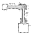
図11は、実施の形態4の流体搬送装置20の構成を示す断面模式図である。実施の形態4における流体搬送装置20は、実施の形態1における流体搬送装置20と比較して、継手13に替えて、第一配管2aと第二配管2bとを連結する連結部が屈曲形成されたエルボ16を有する点が異なる。具体的には、伝熱ブロック8dの内部には90°屈曲したL字状の空間25が形成されている。第一配管2aは、L字状の空間25の一方側から伝熱ブロック8d内に挿通されており、第二配管2bは、空間25の他方側から伝熱ブロック8d内に挿通されている。
図11は、実施の形態4の流体搬送装置20の構成を示す断面模式図である。実施の形態4における流体搬送装置20は、実施の形態1における流体搬送装置20と比較して、継手13に替えて、第一配管2aと第二配管2bとを連結する連結部が屈曲形成されたエルボ16を有する点が異なる。具体的には、伝熱ブロック8dの内部には90°屈曲したL字状の空間25が形成されている。第一配管2aは、L字状の空間25の一方側から伝熱ブロック8d内に挿通されており、第二配管2bは、空間25の他方側から伝熱ブロック8d内に挿通されている。
空間25の内部には、エルボ16が配置されている。エルボ16には、第一配管2aおよび第二配管2bの内径に相当する径を有する貫通孔が形成されており、この貫通孔は90°に屈曲するように形成されている。エルボ16を介在させて第一配管2aと第二配管2bとが連結されている。エルボ16は、第一配管2aおよび第二配管2bを連結する連結部としての機能を有している。
屈曲形成されたエルボ16を、外周にテープヒータを巻回して加熱する場合、テープヒータの巻き方を屈曲部の内周側と外周側とにおいて均一にするのは困難であり、テープヒータによってエルボ16を均一に加熱するのは難しい。また、エルボ16の外周をヒートパイプにより被覆する構成とすると、複雑な形状のヒートパイプを設ける必要があることになり、コストの増大と共にヒートパイプの信頼性の低下を招来する。これに対し、図11に示すように、エルボ16を覆う伝熱ブロック8dから、空気を介した熱伝導および輻射によりエルボ16に熱を伝達する構成とすることにより、エルボ16の温度を精度よく管理することができる。したがって、安価な装置により、エルボ16を均一に加熱することが可能となる。
図12は、実施の形態4の流体搬送装置20の変形例の構成を示す断面模式図である。図12に示す流体搬送装置20では、実施の形態2で説明したように、伝熱ブロック8eの内部にヒートパイプ15が設けられている。このようにすれば、伝熱ブロック8eの温度の均一性を向上させることができるので、伝熱ブロック8eを介して加熱される第一配管2aおよび第二配管2bの温度の均一性をより向上させることができ、かつ、エルボ16の温度の均一性もさらに改善することができる。
さらに、実施の形態1で説明したヒートパイプの動作原理と同様に、加熱部9eがヒートパイプ15の一部を加熱すれば、ヒートパイプ15の全体が均一に加熱される。図11および図12を比較して、図11では伝熱ブロック8dの図右側に加熱部9dが設けられているのに対し、図12に示す変形例では伝熱ブロック8eの図上下側のみに加熱部9eが設けられ、伝熱ブロック8eの図右側には加熱部は設けられていない。したがって、加熱部9eを一部省略することが可能となり、流体搬送装置20の製造コスト低減および信頼性向上を達成することができる。
なお、実施の形態1~4の説明においては、気化器101と反応室102との間に第一配管2aおよび第二配管2bの二本の配管が設けられ、第一配管2aおよび第二配管2bが継手13またはエルボ16を用いて組み合わせられた例について説明した。本発明の流体搬送装置は、この構成に限られるものではなく、複数本の任意の配管が適宜パイプ継手(直線形の継手13、屈曲したエルボ16のほか、三又継手やチーズなど他の継手も含まれる)を介在させて連結されたものに対して適用できる。
また、複数の配管がパイプ継手により連結された構造に限られるものではなく、任意のバルブを介在させて複数の配管が連結されていてもよい。バルブにより連結された配管の場合でも、伝熱ブロックの内部に空間を形成し、当該空間の内部に伝熱ブロックとの間にわずかの隙間を設けてバルブを設置して、伝熱ブロックによりバルブの外周を覆う構成とすれば、上述した実施の形態1~4と同様に、バルブを均一に効率よく加熱することができる。
また、実施の形態1~4においては、ヒートパイプを用いた配管の加熱について述べたが、ヒートパイプから積極的に熱を奪ってヒートパイプの作動流体を冷却させる冷却器を、ヒートパイプと熱的に接触するように設けてもよい。当該冷却器は、たとえば水冷回路、ペルチェ素子など、任意の冷却器を適用することが可能である。
加熱部によるヒートパイプの加熱を停止した後に、冷却器によってヒートパイプを冷却すれば、ヒートパイプの一部を冷却することにより、ヒートパイプ全体の冷却を効率的に行なうことができる。つまり、実施の形態1で説明したヒートパイプの熱輸送動作により、ヒートパイプ全体を冷却する必要はなく、効率的にヒートパイプの冷却を行なうことができる。このようにすれば、メンテナンス時などの配管の温度を下げたい場合に、配管をより高速に均一温度で下げることができるので、配管の温度低下に要する時間を短縮でき、メンテナンス時間を短縮することができる。
以上のように本発明の実施の形態について説明を行なったが、各実施の形態の構成を適宜組合せてもよい。また、今回開示された実施の形態はすべての点で例示であって、制限的なものではないと考えられるべきである。この発明の範囲は上記した説明ではなくて請求の範囲によって示され、請求の範囲と均等の意味、および範囲内でのすべての変更が含まれることが意図される。
本発明の流体搬送装置は、たとえば半導体ウェハや液晶ガラス基板などに成膜対象物を成膜する際の反応ガスなど、高精度の温度管理を必要とする物質を搬送する流体搬送装置に、特に有利に適用され得る。
Claims (5)
- 第一配管(2a)と、
第二配管(2b)と、
前記第一配管(2a)および前記第二配管(2b)を連結する連結部(13)と、
前記第一配管(2a)の外周部を覆う第一外管(3a)と、
前記第二配管(2b)の外周部を覆う第二外管(3b)と、
前記連結部(13)、前記第一外管(3a)の前記連結部(13)側の端部(17a)および前記第二外管(3b)の前記連結部(13)側の端部(17b)を覆う伝熱ブロック(8a)と、
前記伝熱ブロック(8a)に熱的に接触する加熱部(9a)とを備え、
前記第一配管(2a)および前記第一外管(3a)の間には第一空間(22a)が形成され、前記第二配管(2b)および前記第二外管(3b)の間には第二空間(22b)が形成されており、
前記第一空間(22a)および前記第二空間(22b)は、密閉された真空空間であって、内部に作動流体(5)が封入されており、
前記加熱部(9a)は、前記作動流体(5)を加熱して気化させる、流体搬送装置(20)。 - 前記第二外管(3b)の外周面(3d)と、前記伝熱ブロック(8a)との間には隙間(25a)が形成されており、
前記隙間(25a)を覆う断熱材(21)をさらに備える、請求の範囲第1項に記載の流体搬送装置(20)。 - 前記伝熱ブロック(8b)は、前記第一外管(3a)の外周面(3c)および前記第二外管(3b)の外周面(3d)に熱的に接触する、請求の範囲第1項に記載の流体搬送装置(20)。
- 前記伝熱ブロック(8a)の内部に、前記第一配管(2a)または前記第二配管(2b)の延びる方向に沿って延在するヒートパイプ(15)を有する、請求の範囲第1項に記載の流体搬送装置(20)。
- 前記連結部(16)は、屈曲形成されたエルボを有する、請求の範囲第1項に記載の流体搬送装置(20)。
Priority Applications (2)
| Application Number | Priority Date | Filing Date | Title |
|---|---|---|---|
| PCT/JP2009/050130 WO2010079599A1 (ja) | 2009-01-08 | 2009-01-08 | 流体搬送装置 |
| JP2010545658A JP5238042B2 (ja) | 2009-01-08 | 2009-01-08 | 流体搬送装置 |
Applications Claiming Priority (1)
| Application Number | Priority Date | Filing Date | Title |
|---|---|---|---|
| PCT/JP2009/050130 WO2010079599A1 (ja) | 2009-01-08 | 2009-01-08 | 流体搬送装置 |
Publications (1)
| Publication Number | Publication Date |
|---|---|
| WO2010079599A1 true WO2010079599A1 (ja) | 2010-07-15 |
Family
ID=42316377
Family Applications (1)
| Application Number | Title | Priority Date | Filing Date |
|---|---|---|---|
| PCT/JP2009/050130 Ceased WO2010079599A1 (ja) | 2009-01-08 | 2009-01-08 | 流体搬送装置 |
Country Status (2)
| Country | Link |
|---|---|
| JP (1) | JP5238042B2 (ja) |
| WO (1) | WO2010079599A1 (ja) |
Cited By (2)
| Publication number | Priority date | Publication date | Assignee | Title |
|---|---|---|---|---|
| JP2020150046A (ja) * | 2019-03-12 | 2020-09-17 | 株式会社Kokusai Electric | 基板処理装置および半導体装置の製造方法 |
| WO2024069722A1 (ja) * | 2022-09-26 | 2024-04-04 | 株式会社Kokusai Electric | 配管加熱システム、基板処理装置及び半導体装置の製造方法 |
Citations (5)
| Publication number | Priority date | Publication date | Assignee | Title |
|---|---|---|---|---|
| JPH0585890A (ja) * | 1991-09-25 | 1993-04-06 | Matsushita Electric Ind Co Ltd | 薄膜形成装置 |
| JPH06168877A (ja) * | 1992-11-30 | 1994-06-14 | Handotai Process Kenkyusho:Kk | 半導体装置の製造装置 |
| JP2001107250A (ja) * | 1999-10-06 | 2001-04-17 | Ebara Corp | プロセスガス搬送用配管及び成膜装置 |
| JP2004146508A (ja) * | 2002-10-23 | 2004-05-20 | Hitachi Kokusai Electric Inc | 基板処理装置 |
| JP2005223115A (ja) * | 2004-02-05 | 2005-08-18 | Hitachi Kokusai Electric Inc | 基板処理装置 |
-
2009
- 2009-01-08 WO PCT/JP2009/050130 patent/WO2010079599A1/ja not_active Ceased
- 2009-01-08 JP JP2010545658A patent/JP5238042B2/ja active Active
Patent Citations (5)
| Publication number | Priority date | Publication date | Assignee | Title |
|---|---|---|---|---|
| JPH0585890A (ja) * | 1991-09-25 | 1993-04-06 | Matsushita Electric Ind Co Ltd | 薄膜形成装置 |
| JPH06168877A (ja) * | 1992-11-30 | 1994-06-14 | Handotai Process Kenkyusho:Kk | 半導体装置の製造装置 |
| JP2001107250A (ja) * | 1999-10-06 | 2001-04-17 | Ebara Corp | プロセスガス搬送用配管及び成膜装置 |
| JP2004146508A (ja) * | 2002-10-23 | 2004-05-20 | Hitachi Kokusai Electric Inc | 基板処理装置 |
| JP2005223115A (ja) * | 2004-02-05 | 2005-08-18 | Hitachi Kokusai Electric Inc | 基板処理装置 |
Cited By (2)
| Publication number | Priority date | Publication date | Assignee | Title |
|---|---|---|---|---|
| JP2020150046A (ja) * | 2019-03-12 | 2020-09-17 | 株式会社Kokusai Electric | 基板処理装置および半導体装置の製造方法 |
| WO2024069722A1 (ja) * | 2022-09-26 | 2024-04-04 | 株式会社Kokusai Electric | 配管加熱システム、基板処理装置及び半導体装置の製造方法 |
Also Published As
| Publication number | Publication date |
|---|---|
| JP5238042B2 (ja) | 2013-07-17 |
| JPWO2010079599A1 (ja) | 2012-06-21 |
Similar Documents
| Publication | Publication Date | Title |
|---|---|---|
| JP5283758B2 (ja) | 伝熱装置 | |
| CN102277557B (zh) | 真空蒸镀装置中蒸镀材料的蒸发或升华方法及坩埚装置 | |
| JP5183744B2 (ja) | 配管装置および流体搬送装置 | |
| JP6676537B2 (ja) | 基板載置台 | |
| JP5394730B2 (ja) | アニール装置およびアニール方法 | |
| US8284004B2 (en) | Heat pipe supplemented transformer cooling | |
| JP2009168273A (ja) | ループ型ヒートパイプおよび電子機器 | |
| CN101990583B (zh) | 均热装置 | |
| US8342742B2 (en) | Thermal calibrating system | |
| JP5238042B2 (ja) | 流体搬送装置 | |
| JP5181874B2 (ja) | ループヒートパイプおよび電子機器 | |
| KR101456813B1 (ko) | 가열 장치 | |
| JP5759066B2 (ja) | 伝熱装置 | |
| JP5321716B2 (ja) | ループ型ヒートパイプおよび電子機器 | |
| JPWO2017169969A1 (ja) | 冷却装置 | |
| JP2022030149A (ja) | 有機膜形成装置 | |
| JP2010065282A (ja) | 蒸発源 | |
| JPH11257884A (ja) | ヒートパイプを用いた温度制御装置 | |
| KR102233280B1 (ko) | 진동형 히트파이프를 적용한 극저온 루프 히트파이프 | |
| JP2017067329A (ja) | 冷媒の流量制御機構、冷却システムおよび冷媒の流量制御方法 | |
| KR20020086380A (ko) | 유기 반도체 장치에서 기화물질의 운송관의 가열 장치 및방법 | |
| CN117116808A (zh) | 前驱体输送管路温控装置 | |
| JP2013237915A (ja) | 蒸発源及び真空蒸着装置 | |
| KR20170000412U (ko) | 히트파이프를 구비한 진공 증착 소스의 냉각 장치 | |
| KR20150048447A (ko) | 기화기 및 원료 공급 장치 |
Legal Events
| Date | Code | Title | Description |
|---|---|---|---|
| 121 | Ep: the epo has been informed by wipo that ep was designated in this application |
Ref document number: 09837487 Country of ref document: EP Kind code of ref document: A1 |
|
| WWE | Wipo information: entry into national phase |
Ref document number: 2010545658 Country of ref document: JP |
|
| NENP | Non-entry into the national phase |
Ref country code: DE |
|
| 122 | Ep: pct application non-entry in european phase |
Ref document number: 09837487 Country of ref document: EP Kind code of ref document: A1 |