WO2010079572A1 - 追記型情報記録媒体、情報記録装置、情報記録方法、情報再生装置および情報再生方法 - Google Patents
追記型情報記録媒体、情報記録装置、情報記録方法、情報再生装置および情報再生方法 Download PDFInfo
- Publication number
- WO2010079572A1 WO2010079572A1 PCT/JP2009/007250 JP2009007250W WO2010079572A1 WO 2010079572 A1 WO2010079572 A1 WO 2010079572A1 JP 2009007250 W JP2009007250 W JP 2009007250W WO 2010079572 A1 WO2010079572 A1 WO 2010079572A1
- Authority
- WO
- WIPO (PCT)
- Prior art keywords
- information
- recording
- size
- bitmap
- area
- Prior art date
Links
Images


Classifications
-
- G—PHYSICS
- G11—INFORMATION STORAGE
- G11B—INFORMATION STORAGE BASED ON RELATIVE MOVEMENT BETWEEN RECORD CARRIER AND TRANSDUCER
- G11B20/00—Signal processing not specific to the method of recording or reproducing; Circuits therefor
- G11B20/10—Digital recording or reproducing
- G11B20/18—Error detection or correction; Testing, e.g. of drop-outs
- G11B20/1883—Methods for assignment of alternate areas for defective areas
-
- G—PHYSICS
- G11—INFORMATION STORAGE
- G11B—INFORMATION STORAGE BASED ON RELATIVE MOVEMENT BETWEEN RECORD CARRIER AND TRANSDUCER
- G11B20/00—Signal processing not specific to the method of recording or reproducing; Circuits therefor
- G11B20/10—Digital recording or reproducing
- G11B20/12—Formatting, e.g. arrangement of data block or words on the record carriers
- G11B20/1217—Formatting, e.g. arrangement of data block or words on the record carriers on discs
-
- G—PHYSICS
- G11—INFORMATION STORAGE
- G11B—INFORMATION STORAGE BASED ON RELATIVE MOVEMENT BETWEEN RECORD CARRIER AND TRANSDUCER
- G11B20/00—Signal processing not specific to the method of recording or reproducing; Circuits therefor
- G11B20/10—Digital recording or reproducing
- G11B20/12—Formatting, e.g. arrangement of data block or words on the record carriers
- G11B2020/1264—Formatting, e.g. arrangement of data block or words on the record carriers wherein the formatting concerns a specific kind of data
- G11B2020/1265—Control data, system data or management information, i.e. data used to access or process user data
-
- G—PHYSICS
- G11—INFORMATION STORAGE
- G11B—INFORMATION STORAGE BASED ON RELATIVE MOVEMENT BETWEEN RECORD CARRIER AND TRANSDUCER
- G11B20/00—Signal processing not specific to the method of recording or reproducing; Circuits therefor
- G11B20/10—Digital recording or reproducing
- G11B20/18—Error detection or correction; Testing, e.g. of drop-outs
- G11B20/1816—Testing
- G11B2020/1826—Testing wherein a defect list or error map is generated
-
- G—PHYSICS
- G11—INFORMATION STORAGE
- G11B—INFORMATION STORAGE BASED ON RELATIVE MOVEMENT BETWEEN RECORD CARRIER AND TRANSDUCER
- G11B20/00—Signal processing not specific to the method of recording or reproducing; Circuits therefor
- G11B20/10—Digital recording or reproducing
- G11B20/18—Error detection or correction; Testing, e.g. of drop-outs
- G11B2020/1873—Temporary defect structures for write-once discs, e.g. TDDS, TDMA or TDFL
-
- G—PHYSICS
- G11—INFORMATION STORAGE
- G11B—INFORMATION STORAGE BASED ON RELATIVE MOVEMENT BETWEEN RECORD CARRIER AND TRANSDUCER
- G11B2220/00—Record carriers by type
- G11B2220/20—Disc-shaped record carriers
-
- G—PHYSICS
- G11—INFORMATION STORAGE
- G11B—INFORMATION STORAGE BASED ON RELATIVE MOVEMENT BETWEEN RECORD CARRIER AND TRANSDUCER
- G11B2220/00—Record carriers by type
- G11B2220/20—Disc-shaped record carriers
- G11B2220/21—Disc-shaped record carriers characterised in that the disc is of read-only, rewritable, or recordable type
- G11B2220/215—Recordable discs
- G11B2220/216—Rewritable discs
-
- G—PHYSICS
- G11—INFORMATION STORAGE
- G11B—INFORMATION STORAGE BASED ON RELATIVE MOVEMENT BETWEEN RECORD CARRIER AND TRANSDUCER
- G11B2220/00—Record carriers by type
- G11B2220/20—Disc-shaped record carriers
- G11B2220/25—Disc-shaped record carriers characterised in that the disc is based on a specific recording technology
- G11B2220/2537—Optical discs
- G11B2220/2541—Blu-ray discs; Blue laser DVR discs
-
- G—PHYSICS
- G11—INFORMATION STORAGE
- G11B—INFORMATION STORAGE BASED ON RELATIVE MOVEMENT BETWEEN RECORD CARRIER AND TRANSDUCER
- G11B2220/00—Record carriers by type
- G11B2220/20—Disc-shaped record carriers
- G11B2220/25—Disc-shaped record carriers characterised in that the disc is based on a specific recording technology
- G11B2220/2537—Optical discs
- G11B2220/2562—DVDs [digital versatile discs]; Digital video discs; MMCDs; HDCDs
Definitions
- the present invention relates to an information recording medium that includes bit map information indicating a recording state / unrecorded state of each area and is capable of random recording, a recording / reproducing method for the recording medium, and a recording / reproducing apparatus.
- the present invention relates to a write-once optical disc that can be recorded only once, such as high-density BD-R, and recording / reproduction with respect to such a disc.
- an optical disc such as a DVD or Blu-ray Disc (hereinafter also referred to as BD)
- the optical disc drive apparatus performs recording and reproduction by forming minute pits (marks) on an optical disc using laser light, and is therefore suitable for information recording that can be exchanged with a large capacity.
- a laser beam a red laser is used as a DVD, and a blue laser having a shorter wavelength than that of a red laser is used as a laser beam.
- the BD has a higher recording density and a higher capacity than a DVD. For example, in the case of a BD-R, a recording capacity of 27 GB at maximum is realized per recording layer.
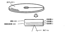
- An example of an optical disk is an optical disk using a phase change type recording material as a recording layer.
- a phase change optical disk records information by irradiating an optical disk with a laser beam and locally changing the atomic bonding state of the thin film material on the recording film surface by the injection energy.
- laser light having a sufficiently lower power than that at the time of recording is irradiated, the reflectance changes due to the difference in the physical state described above.
- Information can be read by detecting the amount of change in reflectance.
- Phase change type optical discs include a write once type optical disc that can be recorded only once, in addition to a rewritable optical disc that can be repeatedly recorded a plurality of times by a phase change type recording material used for a recording layer.
- a recording mark is formed by irradiating a laser beam modulated in a multi-pulse form to cause a change in the physical state of the recording material.
- Information is read by detecting a change in reflectance.
- the optical disk is an exchangeable information recording medium
- the recording surface is defective due to dust or scratches.
- a higher-density recording medium is more susceptible to defects, so that not only a rewritable optical disc (eg, BD-RE) but also a write-once optical disc (eg, BD-R) can be used to guarantee the reliability of recorded / reproduced data.
- a method of performing defect management has become common (for example, Patent Document 1).
- BD-R in addition to a sequential recording mode in which recording is performed continuously from a specific additional recording point, which is a characteristic of a write-once recording medium, a recording mode called a random recording mode in which recording is performed at an arbitrary recording position is provided. It also has a feature of providing (for example, Patent Document 2, Patent Document 3, and Patent Document 4).
- FIG. 1 is an area diagram of a general optical disc.
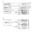
- a disk-shaped optical disk 1 has a large number of tracks 2 formed in a spiral shape, and each track 2 has a large number of finely divided blocks 3 formed therein.
- the block 3 is a unit for error correction, and is the minimum unit for performing recording and reproduction operations.
- the block 3 is called a cluster, or in the case of a DVD, the block 3 is called an ECC.
- One cluster which is one block in the case of BD is, for example, 32 sectors (one sector is 2 Kbytes and one cluster is 64 Kbytes), and one ECC which is one block in the case of DVDs is 16 sectors (32 Kbytes).
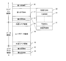
- the area of the optical disc 1 is roughly divided into a lead-in area 4, a data area 5, and a lead-out area 6. Recording / reproduction of user data is performed on the data area 5.
- the lead-in area 4 and the lead-out area 6 serve as margins so that the optical head (not shown) can follow the track even if the optical head overruns when accessing the end of the data area 5. Fulfill.
- This area configuration is common to both rewritable optical discs and write once optical discs.
- FIG. 2 is a diagram showing a data structure of one recording layer of a write-once optical disc having a defect management function.
- the data area 5 includes a user data area 14 for recording / reproducing user data, and a spare area (inner circumference of the optical disc 1) prepared in advance as a block (hereinafter referred to as a replacement block) used instead of a defective block in the user data area 14.
- An inner peripheral spare area 15 prepared on the outer side, and an outer peripheral spare area 16) prepared on the outer peripheral side.
- FIG. 2 the case where one spare area is provided on each of the inner circumference side and the outer circumference side of the data area 5 has been described as an example, but either one (for example, only the inner circumference side) may be provided. Is not as shown in this figure.
- Lead-in area 4 as an area for writing a disk management structure (Disc Management Structure; hereinafter referred to as DMS) that is management information such as spare area arrangement (size) information, recording mode information, and defective block information on optical disk 1
- DMS disk management structure
- DMA 1 Disc Management Area
- DMA 2 Disc Management Area
- DMA 3 Disc Management Area
- DMA 13 Disc Management Area
- DMA4 fourth DMA 13.
- the DMA may also be referred to as Defect Management Area.
- DMA1 to DMA4 are areas arranged at predetermined positions. Here, all of the same management information is recorded in DMA1 to DMA4 except for predetermined information such as position information. This is in preparation for the case where DMA1 to DMA4 themselves are affected by a defect. Even if there is a DMA that cannot be reproduced correctly, the defect management information can be acquired if any one of the DMAs can be reproduced correctly.
- the lead-in area 4 includes a first TDMA (Temporary Disc Management Area) 17.
- the TDMA is an area unique to a write-once optical disc that cannot be rewritten (overwrite updated), and is used to update and update transient management information during use of the optical disc 1.
- TDMA may also be referred to as Temporary Defect Management Area.
- initialization format processing (also referred to as initialization) is performed to determine the arrangement (size) of the spare area and the recording mode to make the write-once type optical disc 1 usable, and as shown in FIG. A TDMS (Temporary Disc Management Structure) 20 is recorded.
- the recording process to the user data area 14 is performed.
- the TDMS 21 # 0 updated to the corresponding information (defect information, end recording position information, etc.) is not recorded in the TDMA 17. Recording is performed at the head position (that is, from the recorded position to the unrecorded side from the unrecorded boundary position).
- the management information is updated in the same manner, and the state shown in FIG. 14C shows the state after the initialization format process and m + 1 times of management information update. That is, the latest management information (latest TDMS) is the recorded TDMS adjacent to the recorded / unrecorded boundary position in the TDMA 17 (in this case, TDMS 21 #m).
- the arrangement of DMA is the same for both write-once optical discs and rewritable optical discs.
- rewritable optical discs can be rewritten (overwrite updated)
- all management information including transient management information during use of optical disc 1 is updated. Can be performed in the DMA area.
- rewriting (overwriting update) cannot be performed in the case of a write-once optical disc.
- TDMA transitional information update area peculiar to the write-once type
- subsequent recording additional write
- finalization Finalize, (Also referred to as Disc Close
- TDMA 17 in the lead-in area 4 has been described as an example, but two or more TDMAs 17 may be provided (for example, Patent Document 5).
- TDMA # 0 in the lead-in area 4 for one recording layer in addition to TDMA # 0 in the lead-in area 4 for one recording layer, TDMA # 1 in the inner spare area 15 in the data area 5 and in the outer spare area 16
- TDMA may be secured also in the spare area, such as TDMA # 2.
- the TDMA may be provided for each recording layer.
- Both the DMS recorded in the DMA and the TDMS 21 recorded in the TDMA 17 are composed of the same elements.
- TDMS 21 will be described as an example.
- FIG. 16 shows components constituting the TDMS 21 in the BD-R which is a write-once optical disc in the random recording mode.
- the write-once type optical disc 1 having only one recording layer will be described as an example, and therefore, the contents of data held by each information are also described only for one recording layer. I will do it.
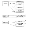
- the TDMS 21 includes a SBM (Space Bit Map) 30, a TDFL (Temporary Defect List) 31, and a TDDS (Temporary Disc Definition Structure) 32.
- SBM Space Bit Map
- TDFL Temporal Defect List
- TDDS Temporal Disc Definition Structure
- the SBM 30 includes an SBM header 40 including an identifier indicating that this information is the SBM 30, update frequency information, information on the area range of the SBM management target (for example, the start address and size of the target area), and the SBM management target And bitmap information 41 indicating a recording state in the area range (for example, a recorded / unrecorded state for each block included in the area range).
- the bitmap information 41 will be described in detail later.
- the data area 5 (more specifically, the user data area 14) that can be managed by the SBM 30 is not physically continuous between the respective layers. Provided for each.
- the TDFL 31 includes a DFL header including information indicating that this information is a TDFL, update count information, and the number of DFL entries 43 that are defect / alternative information included in the TDFL (n + 1 in the case of FIG. 16). 42, the number of DFL entries 43 described above, and a DFL terminator 44 including an identifier indicating the end position of the TDFL 31 whose size changes according to the number of DFL entries 43, update count information, and the like.
- the TDFL 31 is, for example, a combination with a TDDS 32 having a sector size, which will be described later, and has a maximum size of 4 blocks (4 clusters in the case of BD) when the recording layer is 1 layer, and a maximum of 8 blocks in the case of 2 layers ( In the case of BD, the size is 8 clusters). That is, the size of the TDFL 31 is a maximum of “4 blocks (4 clusters in the case of BD) ⁇ 1 sector” when the recording layer is 1 layer, and a maximum of “8 blocks (in the case of BD) in the case of 2 layers. Is the size of 8 clusters) -1 sector ".
- the TDDS 32 includes an identifier indicating that the information is the TDDS 32, a DDS header 50 including update count information, and the inner spare area which is size information of the inner spare area 15 for determining the area structure in the data area 5.
- the outer periphery spare area size 52 which is size information of the size 51 and the outer periphery spare area 16, the recording mode information 53 indicating the recording mode of the sequential recording mode or the random recording mode, and the inner periphery spare area 15 as shown in FIG.
- the inner spare area TDMA size 54 and the outer spare part TDMA size 55 indicating size information when the TDMA is secured in the outer spare area 16, and the SBM which is the position information in which the latest SBM 30 is recorded.
- TDDS 32 has a fixed size, for example, it is assumed that it has a sector size as described above.
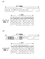
- the bitmap information 41 is information for managing a recorded portion and an unrecorded portion of the data area. For example, recording / unrecording is managed in units of blocks.
- the bitmap information 41 corresponds to one block in the SBM management target area range (for example, the user data area 14) with 1 bit, and is 0 if the block is in an unrecorded state. change. That is, as shown in FIG. 19, 1 byte (8 bits) data at a predetermined Byte position of the bitmap information 41 is associated with 8 blocks from A to H in the area range to be managed by SBM.
- bit0 When bit0 is shown corresponding to block A,..., bit7 corresponds to block H, if all the target areas are unrecorded as shown in FIG. 19A, the corresponding bitmap information 41 is bit0 to bit7. Are all zero.
- bit1, bit2, and bit5 of the corresponding bitmap information 41 become 1, respectively.
- One byte (8 bits) data at the Byte position is 26h (hexadecimal notation). Since 1 block corresponds to 1 bit, 4000h (hexadecimal notation) block can be managed with bitmap information 41 of 1 sector (2 Kbytes), and 78000h (hexadecimal notation. Decimal notation) with bitmap information 41 of 30 sectors. 491, 520) The block can be managed.
- the maximum number of blocks (clusters) included in the user data area 14 is less than 68000h (hexadecimal notation) blocks, so the size of the bitmap information 41 is 30 sectors are enough.
- the SBM header 40 is set to one sector size, it can be guaranteed that the combined size of the 31 sector size SBM 30 and the one sector size TDDS 32 always fits in one block (32 sectors and one cluster).
- the size of the TDFL 31 is variable depending on the number of DFL entries 43, it cannot be guaranteed that the size of the TDFL 31 will always fit within one block size in combination with the TDDS 32.
- the SBM 30 and the TDFL 31 are always recorded in the TDMA 17 in a format combined with the TDDS 32 as one recording unit (this is called a disk management structure update unit).
- the initial TDMS 20 is arranged at the head position of the TDMA 17, that is, the position where it is first used (recorded) in the optical disc 1.
- the initial TDMS 20 includes the same components as the normal TDMS 21, but its contents are slightly different from the TDMS 21. As shown in FIG. 17, the initial TDMS 20 includes data (disk management structure update unit) of one block (one cluster) of the combination of the initial SBM 30 and TDDS 32, followed by one block (1 of the combination of the initial TDFL 31 and TDDS 32). Cluster) data (disk management structure update unit).
- the initial SBM 30 is set only for the identifier of the SBM header 40 and information about the area range to be managed by the SBM, the update count information is 0, and the bitmap information 41 is all 0 (that is, user data).
- Area 14 is an SBM in an unrecorded state.
- (Inside peripheral spare TDMA size 54, outer spare TDMA size 55) and recording mode information 53 (random recording mode in this example) are determined.
- the SBM # 0 position information 56 indicates position information from which the SBM 30 will be recorded.
- DFL # 0 position information 57 corresponding to an initial TDFL 31 described later is recorded.
- the DFL # 0 position information 57 indicates a block position where the initial TDFL 31 and the TDDS 32 are recorded following the initial SBM 30 and the TDDS 32.
- unused DFL # 1 position information 58, DFL # 2 position information 59, and DFL # 3 position information 60 are recorded as data having no meaning (for example, all 0) indicating that these pieces of information do not exist. .
- the initial TDFL 31 is a TDFL of the minimum size that does not include the DFL entry 43 at all. That is, in the initial TDFL 31, only the identifier information is set, the number of DFL entries 43, the update count information, etc. are 0, the DFL header 42 is set, and the identifier information is set, the update count information is only the 0 DFL terminator 44. It is a TDFL provided. Since the initial TDFL 31 is a size that can be accommodated by one sector size, even if it is recorded together with the TDDS 32, it can be accommodated in one block (one cluster) size. The TDDS 32 recorded here has almost the same contents as the TDDS 32 recorded by the initial SBM 30 and the TDDS 32 described above.
- the only difference may be the DFL # 0 position information 57.
- this value is the initial value. It may be different from the value of TDDS32 recorded with SBM30.
- the TDDS 32 having information for determining the area structure and recording mode related to the data area 5 of the optical disc 1 is always recorded at the head position.
- the TDDS 32 having information that can determine the area structure and recording mode regarding the data area 5 of the optical disc 1 is located at any position. Even in the case where it cannot be immediately determined whether it exists, always read the data of the first block of the TDMA 17 (if there is a defect, the first block that can be correctly recorded and reproduced subsequently). Thus, the area structure and recording mode of the data area 5 can be determined.
- the reproduction-only apparatus for the optical disk 1 for example, for the optical disk 1 that does not have a spare area, if the layout (area structure) of the optical disk 1 can be grasped, the latest management information is not acquired and the reproduction from the host is performed. Playback processing can be performed according to the request. For this reason, the management information in the latest state is not necessarily required, and it is preferable that the TDDS 32 indicating the layout of the optical disc 1 can be acquired as soon as possible. From this point of view, it is desirable that data including the TDDS 32 is always recorded at a predetermined position (for example, one block at the head position of the TDMA 17).
- the location where the TDMAs are located cannot be determined unless the size of the TDMAs in the spare area is known. For this reason, it is very important and efficient for an optical disc drive apparatus for recording / reproducing the optical disc 1 to always arrange data that can acquire the TDDS 32 at a predetermined position (in this case, the start position of the TDMA 17). is there.
- the head position of the recording track also referred to as SRR: Sequential Recording Range
- the recorded end position information are provided instead of the SBM 30.
- SRR Sequential Recording Range
- the initial TDMS is the initial TDFL 31 + the initial SRRI + TDDS 32, and fits in the size of one block (one cluster), so it is recorded in the form of one block (one cluster) data.
- TDMS TDDS is arranged at the end position of TDMS
- DDS is arranged at the head position of DMS (for example, Patent Document 1).
- the recording mark 1 and recording space are shortened, and the recording layer 1 increases by about 25% from the maximum 27 GB of the conventional BD size.
- 32 Gbytes and 33.4 GBytes per layer have been studied and may increase further.
- JP 2005-56542 A Japanese Patent No. 3618856 US Pat. No. 7,188,271 US Patent Application Publication No. 2007/0122124 Japanese Patent No. 3865261
- the disk management structure update unit combining the SBM 30 and the TDDS 32 also exceeds the size of one block (two or more blocks).
- the TDDS 32 is located in the second block from the top.
- a normal TDDS 32 is included in any block in order to perform recording until normal recording is performed while performing recording retry on the subsequent block. You have to search while checking if it is.
- bitmap information 41 included in the SBM 30 recorded in the first block of the initial TDMS 20 is a meaningful value for each bit and can be any value. For this reason, for example, there is a possibility that the information of the identifier indicating the TDDS 32 included in the DDS header 50 and the information of the bitmap information 41 may coincide with each other, and the TDDS 32 in the normally recorded block is changed. It becomes very difficult to search.
- the present invention has been made in view of the above-mentioned problems, and even if the size of management information such as the SBM 30 increases with an increase in recording capacity per recording layer, the predetermined position is always obtained.
- an information recording medium in which data including TDDS 32 can be arranged for example, the first block of TDMA 17
- a recording / reproducing method for the information recording medium for example, the first block of TDMA 17
- the write-once information recording medium of the present invention is a write-once information recording medium that includes one or more recording layers and records information in units of blocks, and the write-once information recording medium records user data.
- the user data area is provided for each recording layer, and the management information
- a space bitmap including bitmap information for managing a recording state of the user data area of the recording layer, and a disk definition structure including position information regarding the space bitmap, and the size of the space bitmap is Regardless of the size of the user data area, the size is one block size in combination with the disk definition structure.
- the management information area includes the A one-block size disk management structure update unit including one of a plurality of space bitmaps and the disk definition structure is recorded.
- the bitmap information is divided into a plurality of partial bitmap information, and the plurality of space bitmaps Each includes one of the plurality of partial bitmap information.
- each of the plurality of space bitmaps includes a header including information regarding a region range managed by the partial bitmap information included in each of the plurality of space bitmaps.
- the size of the bitmap information increases as the size of the user data area increases, and the predetermined size includes the bitmap information, the disk definition structure, and the header. This is the size of the user data area when the combined size is one block size.
- the header includes information on a start address and a size of an area range managed by the partial bitmap information.
- the header includes update number information of the space bitmap.
- a block at a predetermined position in the management information area includes a second disk management structure update unit of one block size including the disk management structure update unit, the disk definition structure, and an initial defect list.
- the disc definition structure includes position information of the initial defect list, and the initial defect list is a defect list that does not include information regarding the defect area.
- the block at the predetermined position is the first block among the recordable / reproducible blocks in the management information area.
- the information recording apparatus of the present invention is an information recording apparatus that includes one or more recording layers and records information on a write-once information recording medium in which recording is performed in units of blocks, and the write-once information recording medium includes: A user data area for recording user data; and a management information area for recording management information relating to the write-once information recording medium.
- the user data area is provided for each recording layer, and the management information Includes a space bitmap including bitmap information for managing a recording state of the user data area of the predetermined recording layer, and a disk definition structure including position information regarding the space bitmap, and the space bitmap Regardless of the size of the user data area, the size of one becomes a block size in combination with the disk definition structure.
- the information recording apparatus has a plurality of space bitmaps for the user data area of the predetermined recording layer when the size of the user data area of the predetermined recording layer exceeds a predetermined size. And a block management structure update unit of one block size including one of the plurality of space bitmaps and the disk definition structure is recorded in the management information area.
- the bitmap information is divided into a plurality of partial bitmap information, and the plurality of space bitmaps Each of which includes one of the plurality of partial bitmap information.
- each of the plurality of space bitmaps includes a header including information regarding a region range managed by the partial bitmap information included in each of the plurality of space bitmaps.
- the size of the bitmap information increases as the size of the user data area increases, and the predetermined size includes the bitmap information, the disk definition structure, and the header. This is the size of the user data area when the combined size is one block size.
- the header includes information on a start address and a size of an area range managed by the partial bitmap information.
- the header includes update number information of the space bitmap.
- a block at a predetermined position in the management information area includes a second disk management structure update unit of one block size including the disk management structure update unit, the disk definition structure, and an initial defect list.
- the disc definition structure includes position information of the initial defect list, and the initial defect list is a defect list that does not include information regarding the defect area.
- the block at the predetermined position is the first block among the recordable / reproducible blocks in the management information area.
- the information recording method of the present invention is an information recording method comprising one or more recording layers and recording information on a write-once information recording medium in which recording is performed in units of blocks, wherein the write-once information recording medium comprises: A user data area for recording user data; and a management information area for recording management information relating to the write-once information recording medium.
- the user data area is provided for each recording layer, and the management information Includes a space bitmap including bitmap information for managing a recording state of the user data area of the predetermined recording layer, and a disk definition structure including position information regarding the space bitmap, and the space bitmap Regardless of the size of the user data area, the size of one becomes a block size in combination with the disk definition structure.
- the information recording method includes a plurality of space bitmaps for the user data area of the predetermined recording layer when the size of the user data area of the predetermined recording layer exceeds a predetermined size. And recording a block management structure update unit of one block size including one of the plurality of space bitmaps and the disk definition structure in the management information area.
- the size of the user data area of the predetermined recording layer exceeds the predetermined size, dividing the bitmap information into a plurality of partial bitmap information, and the plurality of spaces Further including including one of the plurality of partial bitmap information in each of the bitmaps.
- each of the plurality of space bitmaps includes a header including information regarding a region range managed by the partial bitmap information included in each of the plurality of space bitmaps.
- the size of the bitmap information increases as the size of the user data area increases, and the predetermined size includes the bitmap information, the disk definition structure, and the header. This is the size of the user data area when the combined size is one block size.
- the header includes information on a start address and a size of an area range managed by the partial bitmap information.
- the header includes update number information of the space bitmap.
- a block at a predetermined position in the management information area includes a second disk management structure update unit of one block size including the disk management structure update unit, the disk definition structure, and an initial defect list.
- the disc definition structure includes position information of the initial defect list, and the initial defect list is a defect list that does not include information regarding the defect area.
- the block at the predetermined position is the first block among the recordable / reproducible blocks in the management information area.
- the information reproduction apparatus of the present invention is an information reproduction apparatus that includes one or more recording layers and reproduces information from a write-once information recording medium on which recording is performed in units of blocks, and the write-once information recording medium includes: A user data area for recording user data; and a management information area for recording management information relating to the write-once information recording medium.
- the user data area is provided for each recording layer, and the management information Includes a space bitmap including bitmap information for managing a recording state of the user data area of the predetermined recording layer, and a disk definition structure including position information regarding the space bitmap, and the space bitmap Regardless of the size of the user data area, the size of a single block size is combined with the disk definition structure.
- a predetermined size If the size of the user data area of the predetermined recording layer exceeds a predetermined size, a plurality of space bitmaps are formed for the user data area of the predetermined recording layer, and the management In the information area, a one-block size disk management structure update unit including one of the plurality of space bitmaps and the disk definition structure is recorded, and the information reproducing apparatus reads from the management information area, The disk management structure update unit of one block size including the disk definition structure is read, and the space bitmap is read.
- the bitmap information is divided into a plurality of partial bitmap information, and the plurality of space bitmaps Each include one of the plurality of partial bitmap information, and the information reproducing apparatus reads the partial bitmap information from the space bitmap.
- each of the plurality of space bitmaps includes a header including information regarding a region range managed by the partial bitmap information included in each of the plurality of space bitmaps.
- the size of the bitmap information increases as the size of the user data area increases, and the predetermined size includes the bitmap information, the disk definition structure, and the header. This is the size of the user data area when the combined size is one block size.
- the header includes information on a start address and a size of an area range managed by the partial bitmap information.
- the header includes update number information of the space bitmap.
- a block at a predetermined position in the management information area includes a second disk management structure update unit of one block size including the disk management structure update unit, the disk definition structure, and an initial defect list.
- the disc definition structure includes position information of the initial defect list, and the initial defect list is a defect list that does not include information regarding a defect area, and the information reproduction
- the apparatus reads either the disk management structure update unit or the second disk management structure update unit from the block at the predetermined position.
- the block at the predetermined position is the first block among the recordable / reproducible blocks in the management information area.
- the information reproducing method of the present invention is an information reproducing method for reproducing information from a write-once information recording medium comprising one or more recording layers and recording is performed in units of blocks, wherein the write-once information recording medium includes: A user data area for recording user data; and a management information area for recording management information relating to the write-once information recording medium.
- the user data area is provided for each recording layer, and the management information Includes a space bitmap including bitmap information for managing a recording state of the user data area of the predetermined recording layer, and a disk definition structure including position information regarding the space bitmap, and the space bitmap Regardless of the size of the user data area, the size of a single block size is combined with the disk definition structure.
- the size of the user data area of the predetermined recording layer exceeds a predetermined size, a plurality of space bitmaps are formed for the user data area of the predetermined recording layer, and the management In the information area, a one-block size disk management structure update unit including one of the plurality of space bitmaps and the disk definition structure is recorded, and the information reproducing method includes the management information area, The step includes reading the disk management structure update unit of one block size including the disk definition structure and reading the space bitmap.
- the bitmap information is divided into a plurality of partial bitmap information, and the plurality of space bitmaps Each include one of the plurality of partial bitmap information, and the information reproducing method further includes a step of reading the partial bitmap information from the space bitmap.
- each of the plurality of space bitmaps includes a header including information regarding a region range managed by the partial bitmap information included in each of the plurality of space bitmaps.
- the size of the bitmap information increases as the size of the user data area increases, and the predetermined size includes the bitmap information, the disk definition structure, and the header. This is the size of the user data area when the combined size is one block size.
- the header includes information on a start address and a size of an area range managed by the partial bitmap information.
- the header includes update number information of the space bitmap.
- a block at a predetermined position in the management information area includes a second disk management structure update unit of one block size including the disk management structure update unit, the disk definition structure, and an initial defect list.
- the disc definition structure includes position information of the initial defect list, and the initial defect list is a defect list that does not include information regarding a defect area, and the information reproduction
- the method further includes the step of reading either the disk management structure update unit or the second disk management structure update unit from a block at a predetermined position in the management information area.
- the block at the predetermined position is the first block among the recordable / reproducible blocks in the management information area.
- the top block of the management information area of the write-once information recording medium Management information including TDDS including the layout information of the write-once information recording medium is always recorded (arranged) at a predetermined position.
- FIG. 1 is a block diagram of an optical disc recording / reproducing apparatus in an embodiment of the present invention. It is a flowchart which shows the initialization format (Initialize) process in Embodiment 1 of this invention.
- (A) And (b) is a figure which shows the data structure of initial stage TDMS in Embodiment 2 of this invention. It is a flowchart which shows the initialization format (Initialize) process in Embodiment 2 of this invention. It is a figure which shows the data structure of initial stage TDMS in Embodiment 3 of this invention.
- (A) And (b) is explanatory drawing regarding the recording information of TDMS and the positional information which TDDS shows in Embodiment 3 of this invention. It is data structure explanatory drawing of the initial SBM in Embodiment 3 of this invention. It is a flowchart which shows the initialization format (Initialize) process in Embodiment 3 of this invention.
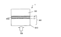
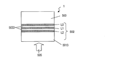
- FIG. 1 It is a figure which shows the structural example of the three-layer disc in embodiment of this invention. It is a figure which shows the structural example of the four layer disc in embodiment of this invention. It is a figure which shows the physical structure of the optical disk in embodiment of this invention.
- (A) is a figure which shows the example of BD of 25 GB
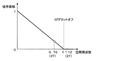
- (B) is a figure which shows the example of the optical disk of higher recording density than BD of 25 GB. It is a figure which shows a mode that the light beam is irradiated to the mark row
- a write-once information recording medium that can be recorded only once is used as the information recording medium.
- the recording capacity (that is, the size of the user data area 14) in one recording layer of this recording medium is such that the SBM 30 is one block size or more (more specifically, the bitmap information 41 is 31 sector sizes or more), and the SBM 30 It is assumed that the combined size of the TDDS 32 is a recording capacity that is a size exceeding one block.
- Embodiment 1 (1) Area Arrangement
- the area structure of the optical disc 1 which is a write-once information recording medium in Embodiment 1 of the present invention is the same as the structure shown in FIG.
- FIG. 3 shows recording at the head of the management information area TDMA 17 (the first TDMA used when there are a plurality of TDMAs) of the optical disc 1 in the first embodiment of the present invention.
- FIG. 2 is a diagram showing a data configuration of an initial disk management structure TDMS 20 to be executed.
- the initial TDMS 20 includes an initial space bitmap SBM 30, a disk definition structure TDDS 32, and an initial defect list TDFL 31. ) Is recorded.
- the initial TDMS 20 shown in FIG. 3 has the same components as the initial TDMS shown in FIG. 17, but the recording order is different. That is, before recording data including the initial SBM 30, one block (one cluster) data (disk management structure update unit) of the combination of the initial TDFL 31 and the TDDS 32 is recorded (arranged) at the head position, followed by the initial 2 blocks (2 clusters) of data (disk management structure update unit) of the combination of SBM 30 and TDDS 32 are recorded (arranged).
- a portion of data having no meaning in the data of the block size is, for example, dummy data such as All0, or padding data indicating no meaning. As a result, data of one block size is generated.
- the size of the SBM 30 increases according to the recording capacity per recording layer, and the size of the disk management structure update unit that combines the SBM 30 and the TDDS 32 becomes more than one block (two or more blocks). Even in this case, the data including the TDDS 32 can always be arranged in one block at the head position of the TDMA 17 (if there is a defect, the first one block that can be correctly recorded and reproduced subsequently).
- this method can achieve the same effect even when applied to the case where the size of the SBM 30 is 31 sectors or less (that is, the SBM 30 and the TDDS 32 can be combined into one block size).
- FIG. 4 is an explanatory diagram of a data structure provided in the TDDS 32 in Embodiment 1 of the present invention.
- the TDDS 32 in FIG. 4 has basically the same configuration as that described with reference to FIG. 16, but further includes SBM # 1 position information 61 in addition to the SBM # 0 position information 56.
- the TDDS 32 in FIG. 4 is the size information of the DDS header 50 including an identifier indicating that this information is the TDDS 32, update count information, and the inner spare area 15 for determining the area structure in the data area 5.
- the peripheral spare area size 51 and the peripheral spare area size 52 which is the size information of the peripheral spare area 16, the recording mode information 53 indicating the recording mode of the sequential recording mode or the random recording mode, and the inner peripheral area as shown in FIG.
- Inner spare TDMA size 54 and outer spare TDMA size 55 indicating size information when TDMA is secured in the spare area 15 and the outer spare area 16, and the latest TDFL 31 (for up to four blocks) are recorded.
- DFL # 0 position information 57, DFL #, which is position information of each block Includes position information 58, DFL # 2 position information 59 and DFL # 3 position information 60, the SBM # 0 position information 56 and the SBM # 1 position information 61 is a position information latest SBM30 is recorded. That is, since the size of the SBM 30 has reached 2 blocks, the SBM position information is increased accordingly.
- FIG. 5 is a diagram for explaining a recording image of the TDMS 21 (FIG. 14) recorded in the TDMA 17 and position information indicated by the TDDS 32. In this figure, description will be made by taking four blocks from block A to block D of TDMA 17 as an example.
- FIG. 5A shows an example in which the data size combining the TDFL 31 and the TDDS 32 is within one block, and when the SBM 30 and the TDFL 31 are recorded simultaneously (that is, when the initial TDMS 20 is recorded, for example). It is.
- the TDFD 31 and TDDS 32 are recorded in the first block A.
- the DFL # 0 position information in the TDDS 32 at this time indicates the head position of the block A where the TDFL 31 is arranged. Since the SBM # 0 position information 56 and the SBM # 1 position information 61 will be recorded from now on, it is recorded in a state where the head positions of the block B and the block C are pointed to as prediction.
- the DFL # 0 position information 57 in the TDDS 32 at this time indicates the head position of the block A in which the TDFL 31 is arranged as in the previous TDDS 32. Also, the SBM # 0 position information 56 and the SBM # 1 position information 61 are recorded in a state in which the head positions of the blocks B and C, which are actually recorded positions, are respectively pointed.
- the two recorded TDDSs 32 are in the state of indicating the same position information.
- FIG. 5B shows an example in which the TDFL 31 has a size exceeding 2 blocks and the recording target block B is defective. Since the TDFL 31 and the TDDS 32 are combined into a three-block size, first, the first block of data (TDFL # 0) is recorded in the block A. However, since the block B is a defective block, the data of the second block (TDFL # 1) is recorded in the subsequent block C, and then the last data (one block data combining TDFL # 2 and TDDS32) is the block. Recorded in D.
- the DFL # 0 position information 57 indicates the head position of the block A
- the DFL # 1 position information 58 indicates the head position of the block C
- the DFL # 2 position information 59 It points to the head position of block D.
- FIG. 5C shows a case where the data size of the combination of the TDFL 31 and the TDDS 32 fits in one block as in FIG. 5A, where the SBM 30 and the TDFL 31 are recorded simultaneously, and the block to be recorded. This is an example when C is a defect.
- TDFL 31 and TDDS 32 are recorded in the first block A.
- the DFL # 0 position information in the TDDS 32 at this time indicates the head position of the block A in which the TDFL 31 is arranged, and the SBM # 0 position information 56 and the SBM # 1 position information 61 will be recorded from now on. As shown, the prediction is recorded with pointing to the head positions of the blocks B and C, respectively.
- the DFL # 0 position information 57 indicates the head position of the block A in which the TDFL 31 is arranged, as in the previous TDDS 32.
- the SBM # 0 position information 56 and the SBM # 1 position information 61 are actually recorded positions, that is, the SBM # 0 position information 56 indicates the block B.
- the SBM # 1 position information 61 is Unlike the contents of the TDDS 32 recorded in the block A by prediction, the head position of the block D is indicated.
- the two recorded TDDSs 32 are partially different in content, but are always the latest TDDS 32 (in the case of FIG. 5C, the TDDS 32 recorded in the block D). The correct information will be recorded in.
- the SBM # 0 position information 56 and the SBM # 1 position information 61 are described.
- the recording order of the TDMS 21 is shown as an example in which the TDFL 31 is recorded before the SBM 30, but this order is necessary because the initial TDMS 20 of the above (2).
- the SBM 30 may be recorded before the TDFL 31.
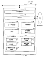
- FIG. 6 is a diagram showing a configuration of an optical disc recording / reproducing device 100 that performs recording / reproducing on the optical disc 1 in the embodiment of the present invention.
- the apparatus 100 may be a recording apparatus or a reproduction-only apparatus.
- the optical disc recording / reproducing apparatus 100 is connected to a host controller (not shown) via the I / O bus 180.
- the host control device is, for example, a host computer (host PC).
- the optical disc recording / reproducing apparatus 100 outputs a command processing unit 110 that processes a command from the host controller, an optical head 120 that irradiates a laser beam to perform recording / reproduction on the optical disc 1, and the optical head 120.
- a system control unit 170 for performing the above.
- the system control unit 170 determines a recording unit 171 and a reproducing unit 172 that perform recording and reproduction of data such as user data and management information, and a position where data is read from the management information related to the optical disc 1 and a position where data is recorded next.
- the access location management unit 173, the management information update unit 174 that updates the management information stored in the management information storage memory 160, and the data that needs to be updated from the SBM 30, TDFL 31, and TDDS 32 stored in the management information storage memory 160
- a management information generation unit 175 that generates TDMS 21 and DMS for recording in combination with TDMA or DMA is provided.
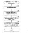
- FIG. 7 is a flowchart showing a procedure in which the optical disc recording / reproducing apparatus 100 performs initialization format processing (Initialization) on the write-once optical disc 1.
- Step 701 Generate management information in the initial state.
- the management information generation unit 175 generates the initial SBM 30, TDFL 31, and TDDS 32 in the management information storage memory 160.
- the SBM 30, TDFL 31, and TDDS 32 in the initial state are management information in which only the identifier information and the like are set and the number of updates is all 0, and the SBM 30 and the TDFL 31 are the initial SBM 30 and the initial SBM 30 respectively. It has the same meaning as TDFL31.
- Step 702 An initial TDMS 20 is generated. Specifically, the management information generation unit 175 combines the SBM 30, the TDFL 31, and the TDDS 32 so that the management information in the initial state generated in step 701 is in the format of the initial TDMS 20 in the state shown in FIG. Create an initial TDMS 20 of the form. More specifically, for example, a data area for 3 blocks to be used for recording is secured in the management information storage memory 160, and all the areas are cleared with 0 data, and the first block of the first block is stored. An initial TDFL 31 is arranged at the beginning and a TDDS 32 is arranged at the end of the first block.
- the initial SBM 30 is arranged from the beginning of the second block, and finally, the TDDS 32 is arranged at the end of the third block to generate data corresponding to the initial TDMS 20.
- the value of the TDDS 32 is changed by updating position information in steps 703 and 705, which will be described later. Therefore, the TDDS 32 is not arranged at this point and is preferably arranged immediately before recording.
- Step 703 Update the position information on the TDFL 31.
- the management information update unit 174 updates the DFL position information in the data corresponding to the TDDS 32 generated in the management information storage memory 160 when recording from now on. More specifically, the system control unit 170 calculates a recording position where the initial TDMS 20 can be recorded (for example, the start position of the TDMA 17) by the access position management unit 173.
- the management information update unit 174 updates the DFL # 0 position information 57 to indicate the recording position calculated by the access position management unit 173 (for example, the start position of the TDMA 17), and the DFL # 1 position information 58 and the DFL # 2 position information 59 , DFL # 3 position information 60 is set to 0, respectively.
- this data is arranged at a predetermined position (in this case, the end position of the first block) of the recording data area secured in the management information storage memory 160.
- the position information regarding the SBM 30 cannot be determined yet to be recorded, so it may be left as 0, or it is assumed that it is normally recorded. Prediction and position information may be set in the prediction.
- Step 704 A part of the initial TDMS 20 is recorded. Specifically, the system control unit 170 sets recording conditions such as laser power and strategy for recording in the laser control unit 130. In step 703, the optical head 120 is moved using the mechanical control unit 140 to the recording position obtained by the access position management unit 173. The recording unit 171 records the initial combination data of the TDFL 31 and the TDDS 32 that is the first block data of the initial TDMS 20. If recording to this block fails, the processing is repeated from step 703, and recording is repeated until normal recording is performed.
- the system control unit 170 sets recording conditions such as laser power and strategy for recording in the laser control unit 130.
- the optical head 120 is moved using the mechanical control unit 140 to the recording position obtained by the access position management unit 173.
- the recording unit 171 records the initial combination data of the TDFL 31 and the TDDS 32 that is the first block data of the initial TDMS 20. If recording to this block fails, the processing is repeated from step 703, and recording is repeated until normal recording is performed.
- Step 705 Update the location information related to the SBM 30.
- the management information update unit 174 updates the SBM position information in the data corresponding to the TDDS 32 generated in the management information storage memory 160 when recording from now on.
- the system control unit 170 uses the access position management unit 173 to record the next recordable position following the position where a part of the initial TDMS 20 was recorded in step 704 (for example, step 704 is recorded once). If successful, the position of the second block from the top of the TDMA 17 is calculated.
- the management information update unit 174 updates the SBM # 0 position information 56 so as to indicate the recording position calculated by the access position management unit 173 (for example, the start position of the second block from the start of the TDMA17), and the SBM # 1 position information 61 is updated to indicate the next block position (for example, the start position of the third block from the start of the TDMA 17).
- the DFL # 0 position information 57 is recorded with the contents indicating the position recorded in step 704.
- the DFL # 1 position information 58, the DFL # 2 position information 59, and the DFL # 3 position information 60 are each recorded as 0 (that is, the same state as the TDDS 32 recorded in step 704).
- Step 706 A part of the initial TDMS 20 is recorded. Specifically, the system control unit 170 sets recording conditions such as laser power and strategy for recording in the laser control unit 130. In step 705, the optical head 120 is moved using the mechanical control unit 140 to the recording position obtained by the access position management unit 173. The recording unit 171 records the combination data of the initial SBM 30 and the TDDS 32, which is the data of the second block, which is the remaining two blocks of the initial TDMS 20, and the data of the third block. If there is a block that has failed to be recorded, the processing is repeated again from step 705 for the block that has failed to be recorded, and recording is repeated until all the blocks are normally recorded.
- the system control unit 170 sets recording conditions such as laser power and strategy for recording in the laser control unit 130.
- the optical head 120 is moved using the mechanical control unit 140 to the recording position obtained by the access position management unit 173.
- the recording unit 171 records the combination data of the initial SBM 30 and the TDDS 32, which is the data of the second block, which
- the TDDS 32 includes update number information in the DDS header 50.
- the number of updates is recorded as a value indicating information recorded at the time of the initialization format, such as 0.
- the update count information may be recorded as 0, but the TDDS 32 is recorded twice during the initialization format. Recording will be done.
- recording is performed with the update count information set to zero.
- the TDDS 32 to be recorded first may be recorded with the update count information set to 0 and the TDDS 32 recorded for the second time set to 1 with the update count information set to a pure update count.
- FIG. 8 shows recording at the head of the management information area TDMA 17 (the TDMA used first when there are a plurality of TDMAs) in the second embodiment of the present invention.
- FIG. 2 is a diagram showing a data configuration of an initial disk management structure TDMS 20 to be executed.
- the initial TDMS 20 according to the second embodiment of the present invention is different from the initial SBM 30 according to the first embodiment of the present invention in the contents of the initial space bitmap SBM 30.
- the initial SBM 30 included in the initial TDMS 20 in Embodiment 2 of the present invention is characterized in that it includes only the SBM header 40 and does not include the bitmap information 41 as shown in FIG.
- the initial TDMS 20 When the initial TDMS 20 is recorded, that is, when the initialization format (Initialization) is performed, the data area 5 and the area of the optical disc 1 are in an unrecorded state. That is, the bitmap information 41 of the SBM 30 included in the initial TDMS 20 is all zero data. That is, it can be determined that the bitmap information 41 of the initial TDMS 20 is not recorded. Therefore, for the purpose of suppressing the size of the initial TDMS 20, the feature of the present embodiment is that the initial SBM 30 does not include the bitmap information 41 and is information of only the SBM header 40.
- FIG. 8 (a) is an example of the initial TDMS 20, and it is sufficient that the initial defect lists TDFL31 and TDDS32 that need to be incorporated into the initial TDMS 20 and recorded have a size of one sector. Also, since it is sufficient for the initial SBM 30 to have a size of one sector, only in the case of the initial TDMS 20, only one block of data combining the initial SBM 30, the initial TDFL 31, and the TDDS 32 is treated as a disk management structure update unit. This information is recorded in one block.
- FIG. 8B is also an example of the initial TDMS 20, and in the first block in the initial TDMS 20, as in the first embodiment of the present invention, one block of data (disk management structure) combining the initial TDFL 31 and the TDDS 32 Update unit) is recorded (arranged) at the head position. Subsequently, one block of data (disk management structure update unit) combining the initial SBM 30 and TDDS 32 is recorded (arranged) in the next block.
- the data including the TDDS 32 is changed to one block at the head position of the TDMA 17 (if it is defective)
- the first block that can be correctly recorded / reproduced thereafter can always be arranged.
- the configuration of the optical disc recording / reproducing device 100 that performs recording / reproducing on the optical disc 1 according to the second embodiment of the present invention is the same as that of the optical disc recording / reproducing device according to the first embodiment of the present invention described with reference to FIG. The same as 100.
- FIG. 9 shows a procedure in which the optical disc recording / reproducing apparatus 100 performs initialization format processing (Initialization) on the write-once optical disc 1 according to Embodiment 2 of the present invention. It is a flowchart which shows.
- the initial TDMS 20 will be described by taking as an example a case where recording is performed in one block as shown in FIG.
- the procedure for recording in the form of FIG. 8B is basically the same as the procedure shown in FIG. 7 in the section (5) of the description of Embodiment 1 of the present invention. The description is omitted here.
- Step 901 Generate management information in the initial state.
- the management information generation unit 175 generates the initial SBM 30, TDFL 31, and TDDS 32 in the management information storage memory 160.
- the SBM 30, TDFL 31, and TDDS 32 in the initial state are management information in which only the identifier information and the like are set and the number of updates is all 0, and the SBM 30 and the TDFL 31 are the initial SBM 30 and the initial SBM 30 respectively. It has the same meaning as TDFL31.
- Step 902 An initial TDMS 20 is generated. Specifically, the management information generation unit 175 combines the SBM 30, TDFL 31, and TDDS 32 so that the management information in the initial state generated in step 901 is in the format of the initial TDMS 20 in the state shown in FIG.
- the initial TDMS 20 having the above recording format is created. More specifically, for example, a data area for one block to be used for recording is secured in the management information storage memory 160, and all the areas are cleared with 0 data, and the first 1 of this block is set.
- An initial TDFL 31 is arranged in a sector, an initial SBM 30 is arranged at a position one sector before the end of this block, and a TDDS 32 is arranged in one sector at the end to generate data corresponding to the initial TDMS 20.
- the value of the TDDS 32 is changed by updating the position information in step 903, which will be described later. Therefore, the TDDS 32 is not arranged at this time but is preferably arranged immediately before recording.
- Step 903 The position information regarding the TDFL 31 and the SBM 30 is updated.
- the management information update unit 174 updates the DFL position information and the SBM position information in the data corresponding to the TDDS 32 generated in the management information storage memory 160 when recording from now on. More specifically, the system control unit 170 calculates a recording position where the initial TDMS 20 can be recorded (for example, the start position of the TDMA 17) by the access position management unit 173.
- the management information update unit 174 updates the DFL # 0 position information 57 to indicate the recording position calculated by the access position management unit 173 (for example, the start position of the TDMA 17), and the DFL # 1 position information 58 and the DFL # 2 position Information 59 and DFL # 3 position information 60 are set to 0, respectively. Further, the SBM # 0 position information 56 is also updated to indicate the recording position of the same block (for example, the 31st sector start position from the start of the start block of TDMA17).
- the SBM # 1 position information 61 is set to 0, for example, or a value indicating that valid bitmap information 41 exists but the information has not yet been recorded (for example, FFFFFFFFh (hexadecimal notation)) And Then, this data is arranged at a predetermined position (in this case, the end position of the first block) of the recording data area secured in the management information storage memory 160.
- Step 904 A part of the initial TDMS 20 is recorded. Specifically, the system control unit 170 sets recording conditions such as laser power and strategy for recording in the laser control unit 130. In step 903, the optical head 120 is moved using the mechanical control unit 140 to the recording position obtained by the access position management unit 173. The recording unit 171 records the combination data of the initial SBM 30, which is the initial TDMS 20, the initial TDFL 31, and the TDDS 32. If recording to this block fails, the processing is repeated from step 903, and recording is repeated until normal recording is performed.
- the initial SBM 30 which is the initial TDMS 20, the initial TDFL 31, and the TDDS 32.
- data including the TDDS 32 can always be arranged at the head position of the TDMA 17. For this reason, even when the data size of the management information is increased due to multi-layering / high-density, etc., the area of the optical disc 1 can be read by reading the data at a predetermined position without searching for the latest management information in the TDMA 17. It becomes possible to grasp the structure.
- Embodiment 3 (1) Area Arrangement
- the area structure of the optical disc 1 in Embodiment 3 of the present invention is the same as that of the optical disc 1 in Embodiment 1 of the present invention.
- FIG. 10 is recorded at the head of the management information area TDMA 17 (TDMA used first when there are a plurality of TDMAs) in the third embodiment of the present invention.
- FIG. 2 is a diagram showing a data configuration of an initial disk management structure TDMS 20 to be executed.
- the initial TDMS 20 according to the third embodiment of the present invention is the same as the first embodiment of the present invention in terms of the configuration of the initial space bitmap SBM 30, but this recording method is different from that of the first embodiment of the present invention. .
- the initial TDMS 20 shown in FIG. 10 is composed of the initial space bitmap SBM 30, the disk definition structure TDDS 32, and the initial defect list TDFL 31, as in the case shown in FIG. 17, but the recording method is different.
- the SBM 30 that combines the SBM header 40 of 1 sector size and the bitmap information 41 of 31 sector size or more has a size of 32 sectors (1 block) or more.
- such SBM 30 is converted to 31 sectors.
- the combined size of the SBM header 40 and the bitmap information 41 is the size of one block and one sector (the SBM header 40 has one sector size and the bitmap information 41 has a total of 33 sector sizes, 33 SBM 30 # 0 including 17-sector-size valid data (partial bitmap information 41 # 0) consisting of the SBM header 40 and the first 16 sectors of the bitmap information 41, and bitmap information
- the initial SBM 30 # 1 having effective data (partial bitmap information 41 # 1) of the latter half of 16 sectors is formed, and a TDDS 32 is combined with each to form and record a disk management structure update unit.
- recording can be performed so that TDDS 32 is arranged for all blocks.
- the size of the user data area 14 when the combined size of the bitmap information 41, the TDDS 32, and the SBM header 40 is one block size is a predetermined size. If the size of the user data area 14 in the predetermined recording layer exceeds the predetermined size, the bitmap information 41 includes a plurality of pieces of partial bitmap information (for example, the size of the user data area 14 is 2 with a predetermined size). In the case of a size less than or equal to double, it is divided into (partial bitmap information 41 # 0 and partial bitmap information 41 # 1). Each of the plurality of space bitmaps (SBM30 # 0, SBM30 # 1) includes one of the plurality of partial bitmap information. Each of the sizes of the plurality of space bitmaps (SBM30 # 0, SBM30 # 1) is a size that becomes one block size in combination with TDDS32.
- each one block data combining the initial SBM30 # 0 and the initial SBM30 # 1 and the TDDS32 data other than 17 sectors of the initial SBM30 # 0 and 1 sector of the TDDS32 is not used.
- data other than the initial two sectors of SBM 30 # 1 and one sector of TDDS 32 are not used.
- Such unused data is, for example, dummy data of ALL0 as meaningless data or padding data indicating that it has no meaning, and generates data of one block size in combination with these unused data. Record.
- the size of the SBM 30 increases in accordance with the recording capacity per recording layer (the size of the user data area 14), and is a disk management structure update unit that combines the SBM 30 and the TDDS 32. Even when the size exceeds 1 block (2 blocks or more), the data including TDDS32 can always be allocated in one block at the head position of TDMA17 by arranging as described above. If it is a defect, it can always be placed in the first block that can be correctly recorded and reproduced subsequently). More specifically, with this arrangement, the TDDS 32 can be recorded for all blocks of the TDMA 17 in which the initial TDMS 20 is recorded.
- this recording method may be applied not only to the initialization format (initial TDMS 20) but also to the TDMS 21 during normal TDMA recording.
- Bit map information 41 of 32 sectors is divided into partial bitmap information of data for the first 16 sectors and data for the second 16 sectors, and is SBM 30 # 0 which is the first half block of SBM 30 in initial TDMS 20 and one block of the second half.
- SBM30 # 1 was demonstrated. The merit of this arrangement will be described below.
- the recorded area is the area managed by the first 16 sectors in the bitmap information 41. If there is only the corresponding block, only the first 16 sectors in the bitmap information 41 are changed, and the latter 16 sectors are not changed from the previous state.
- the SBM 30 # 0 including the data (partial bitmap information 41 # 0) for the first 16 sectors of the bitmap information 41 needs to be updated in the SBM 30.
- the first 16 sectors of the bitmap information 41 (partial bitmap information 41 # 0) in the SBM management target area range managed by the bitmap information 41 in the SBM 30 When the bitmap information 41 is changed only in the area managed in step S4, only the changed SBM 30 # 0 needs to be updated as shown in FIG.
- the SBM # 0 position information 56 indicated by the TDDS 32 is changed to a state indicating the head position of the newly recorded block D.
- the SBM # 1 position information 61 is stored in the block B which is the previously recorded position. Just keep pointing at the beginning.
- the TDMA 17 which is an information area can be used efficiently.
- the update count information included in the SBM header 40 becomes a problem. That is, every time the SBM 30 is updated and recorded, the update count information in the SBM header 40 must be increased and recorded. Therefore, if the SBM header 40 is included only in the SBM 30 # 0 as described with reference to FIG. 10, the area managed by the partial bitmap information 41 # 1 included in the SBM 30 # 1 is recorded. Even if only the partial bitmap information 41 # 1 of the SBM 30 # 1 has changed, not only the SBM 30 # 1, but also the SBM 30 # 0 including the SBM header 40 having the update count information is not recorded at the same time. It will not be.
- all 1-block size disk management structure update units including bitmap information 41 may be provided with an SBM header 40. That is, the SBM header 40 may be provided not only in the SBM 30 # 0 but also in the SBM 30 # 1. In this case, the SBM 30 # 1 has a configuration including effective data (partial bitmap information 41 # 1) having a 17-sector size including the SBM header 40 and the latter 16 sectors of the bitmap information 41. Thus, a plurality of (two in the above example) independent SBMs 30 are provided.
- the SBM header 40 includes information related to the area range of the SBM management target.
- the user data area 14 to be managed in the bitmap information 41 is divided into two areas, an area range managed by the SBM 30 # 0 and an area range managed by the SBM 30 # 1, and the SBM header 40 for managing each is divided.
- the SBM header 40 including information on the area range to be managed by the SBM is provided in each of the SBM 30 # 0 and the SBM 30 # 1. It is desirable to keep it. Further, also from the viewpoint of updating the update count information described above, when performing partial update of the SBM 30, it is desirable to provide the SBM header 40 in each of the SBM 30 # 0 and the SBM 30 # 1.
- each of the plurality of space bitmaps (SBM30 # 0, SBM30 # 1) managing the user data area 14 in the predetermined recording layer is a plurality of space bitmaps (SBM30 # 0, SBM30 # 1).
- You may include the header (SBM header 40) provided with the information regarding the area range managed by the partial bitmap information (partial bitmap information 41 # 0, partial bitmap information 41 # 1) included in each.
- each header (SBM header 40) of the plurality of space bitmaps (SBM30 # 0, SBM30 # 1) may include update count information of the space bitmap SBM30.
- the SBM 30 Only # 1 can be updated. If the partial bitmap information of both SBM 30 # 0 and SBM 30 # 1 has changed, TDMS 21 including both SBM 30 # 0 and SBM 30 # 1 is recorded in TDMA 17. However, if only the partial bitmap information 41 # 1 of the SBM 30 # 1 changes, the TDMS 21 that includes the SBM 30 # 1 but does not include the SBM 30 # 0 is recorded in the TDMA 17.
- the space bitmap including the specific partial bitmap information is updated and only recorded in the management information area TDMA17. It's okay.
- the recording is performed in the management area of the space bitmap including the specific partial bitmap information, it is not necessary to update all the space bitmaps and record them in the management information area TDMA17. In this way, since only the portion of the management information that needs to be updated can be recorded in the TDMA 17, the management information area TDMA17 can be used more efficiently.
- the 32-sector-sized bitmap information 41 is divided and divided into the partial bitmap information of SBM30 # 0 and SBM30 # 1 and allocated equally to the first 16 sectors and the latter 16 sectors.
- the allocated size is not limited to this.
- the size of the area managed by the bitmap information 41 included in the SBM 30 # 0 including the SBM header 40 that must be recorded every time the SBM 30 is recorded in the TDMA 17 is set to the SBM 30 not including the SBM header 40. It is set larger than the size of the area managed by the bitmap information 41 included in # 1. As a result, the larger the area managed by the bitmap information 41, the higher the probability that the bitmap information 41 changes, and as a result, the number of times that the SBM 30 # 1 has to be updated can be suppressed.
- TDMS21 including both SBM30 # 0 and SBM30 # 1 is recorded in TDMA17.
- a method of recording the TDMS 21 including the SBM 30 # 1 but not the SBM 30 # 0 in the TDMA 17 can be used. As a result, it is possible to obtain the above-described effect that only the portion of the management information that needs to be updated can be recorded in the TDMA 17.
- the header (SBM header 40) of a plurality of space bitmaps includes an identifier indicating that this information is a space bitmap (SBM30 # 0, SBM30 # 1), and a space bit.
- Information regarding a management target area range managed by partial bitmap information (partial bitmap information 41 # 0, partial bitmap information 41 # 1) included in each map (SBM30 # 0, SBM30 # 1) may be included.
- Information regarding the area range managed by such partial bitmap information is, for example, the start address and size of the target area.
- the allocation method can be easily changed, such as assigning the management area of the space bitmap to an arbitrary size, It is also possible to widen the range of user selection (degree of freedom).
- the configuration of the optical disc recording / reproducing device 100 that performs recording / reproducing on the optical disc 1 according to the third embodiment of the present invention is the same as that of the optical disc recording / reproducing device according to the first embodiment of the present invention described with reference to FIG. The same as 100.
- the size of the user data area 14 in a predetermined recording layer is a predetermined size (bitmap information 41 and TDDS 32).
- bitmap information 41 and TDDS 32 A process in the case where the combined size of the SBM header 40 exceeds the size of the user data area when the size becomes one block size will be described.
- a plurality of space bitmaps (SBM30 # 0, SBM30 # 1) are formed for the user data area 14 in the predetermined recording layer.
- a one-block size disk management structure update unit including one of a plurality of space bitmaps (SBM30 # 0, SBM30 # 1) and the disk definition structure TDDS32 is recorded in the management information area TDMA17.
- the recording process as described above and the recording process described later are performed by the system control unit 170 (FIG. 6) controlling each component of the recording / reproducing apparatus 100 and the optical head 120 irradiating the optical disk 1 with laser light. Is called.
- the size of the user data area 14 of the predetermined recording layer is set to a predetermined size (the size of the user data area 14 when the size of the bitmap information 41, the TDDS 32, and the SBM header 40 is one block size).
- the bitmap information 41 is divided into a plurality of partial bitmap information (partial bitmap information 41 # 0, partial bitmap information 41 # 1).
- each of the plurality of space bitmaps may include one of the plurality of partial bitmap information.
- the above-mentioned disk management structure update unit is recorded in a block at a predetermined position in the management information area TDMA17. Further, instead of such a disk management structure update unit, a second disk management structure update unit of one block size including the disk definition structure TDDS 32 and the initial defect list TDFL 31 may be recorded. At this time, the disk definition structure TDDS 32 may include initial defect list position information.
- the initial defect list TDFL 31 is a TDFL of the minimum size that does not include any DFL entry 43 that is information regarding the defect area. That is, the initial defect list TDFL 31 includes only the identifier information and the like, and the number of DFL entries 43 and the update count information and the like are 0 DFL headers 42, and the identifier information is set and the update count information is only the 0 DFL terminator 44. It is a TDFL provided. Since the initial TDFL 31 is a size that can be accommodated in one sector size, even if it is recorded together with the TDDS 32, it can be accommodated in one block (one cluster) size.
- the above-mentioned block at a predetermined position in the management information area TDMA17 is, for example, the first block among the recordable / reproducible blocks in the management information area TDMA17.
- the optical head 120 receives reflected light obtained by irradiating the optical disc 1 with laser light to obtain a reproduction signal, and the system control unit 170 (FIG. 6) controls each component of the recording / reproducing apparatus 100. Then, it is executed by performing signal processing.
- a plurality of space bitmaps (SBM30 # 0, SBM30 # 1) are formed for the user data area 14 in a predetermined recording layer, and a plurality of space bitmaps (SBM30 # 0) are stored in the management information area TDMA17 of the optical disc 1.
- SBM30 # 1) and a disk management structure update unit of one block size including the disk definition structure TDDS32 are stored in the management information area TDMA17 of the optical disc 1.
- a one-block size disc management structure update unit including the disc definition structure TDDS 32 is read, and a space bitmap (SBM30 # 0 or SBM30 # 1) is read.
- the bitmap information 41 is divided into a plurality of partial bitmap information (partial bitmap information 41 # 0, partial bitmap information 41 # 1), and a plurality of space bitmaps (SBM30 #).
- 0, SBM30 # 1) includes one of a plurality of pieces of partial bitmap information.
- a space bitmap may be read from the optical disc 1 and partial bitmap information (partial bitmap information 41 # 0 or partial bitmap information 41 # 1) may be read from the space bitmap.
- a disc management structure update unit is recorded, or one block size including the disc definition structure TDDS32 and the initial defect list TDFL31.
- a second disk management structure update unit is recorded.
- the disk management structure update unit or the second disk management structure update unit may be read from a block at a predetermined position in the management information area TDMA17.
- the disk definition structure TDDS 32 may include initial defect list position information.
- the block at a predetermined position in the management information area TDMA17 is, for example, the first block among the recordable / reproducible blocks in the management information area TDMA17.
- FIG. 13 shows a procedure for the optical disc recording / reproducing apparatus 100 to perform initialization format processing (Initialization) on the write-once optical disc 1 according to Embodiment 3 of the present invention. It is a flowchart.
- Step 1301 Generate management information in the initial state.
- the management information generation unit 175 generates the initial SBM 30, TDFL 31, and TDDS 32 in the management information storage memory 160.
- the SBM 30, TDFL 31, and TDDS 32 in the initial state are management information in which only the identifier information and the like are set and the number of updates is all zero.
- SBM30 and TDFL31 have the same meaning as the initial SBM30 and initial TDFL31, respectively.
- Step 1302 An initial TDMS 20 is generated. Specifically, the management information generation unit 175 combines the SBM 30, TDFL 31, and TDDS 32 with the initial state management information generated in step 1301 in the form of the initial TDMS 20 in the state shown in FIG. Create an initial TDMS 20 in recording format.
- the size of the SBM 30 is a total of 33 sectors of 1 block and 1 sector
- a data area for 3 blocks to be used for recording is secured in the management information storage memory 160. All areas are cleared with 0 data.
- the data of 17 sectors in the first SBM 30 from the beginning of the first block (the 1 sector of the SBM header 40 and the first 16 sectors of the bitmap information 41 (partial bitmap information 41 # 0) total 17 sector sizes.
- the initial SBM30 # 0) is arranged.
- the TDDS 32 is arranged at the end sector of the first block.
- data for the last 16 sectors in the initial SBM 30 from the beginning of the second block is arranged.
- the TDDS 32 is arranged at the end sector of the second block.
- An initial TDFL 31 is placed at the beginning of the third block.
- the TDDS 32 is arranged at the end sector of the third block. In this way, data corresponding to the initial TDMS 20 is generated.
- each of the plurality of space bitmaps (SBM30 # 0, SBM30 # 1) for managing the user data area 14 in the predetermined recording layer is a portion included in each of the plurality of space bitmaps. It may include a header (SBM header 40) provided with information related to an area range managed by bitmap information (partial bitmap information 41 # 0, partial bitmap information 41 # 1).
- the data to be arranged at the head of the second block in the data area secured in the management information storage memory 160 is data corresponding to one sector of the SBM header 40 and the latter 16 sectors in the initial SBM 30 (partial bitmap).
- the data is 17 sectors including the initial SBM 30 # 1) including the information 41 # 1.
- the SBM header 40 may include an identifier indicating that this information is a space bitmap, and information (for example, the start address and size of the target area) regarding each area range to be managed of the space bitmap. Further, the SBM header 40 may include update count information of the space bitmap SBM 30.
- the value of the TDDS 32 is changed by updating the position information in steps 1303, 1305, and 1307, which will be described later. Therefore, the TDDS 32 is preferably not placed at this time but immediately before recording.
- Step 1303 Update the position information related to the SBM 30.
- the management information update unit 174 updates the SBM position information in the data corresponding to the TDDS 32 generated in the management information storage memory 160 when recording from now on. More specifically, the system control unit 170 uses the access position management unit 173 to calculate a recording position where the initial TDMS 20 can be recorded (for example, the start position of the TDMA 17).
- the management information update unit 174 updates the SBM # 0 position information 56 so as to indicate the recording position calculated by the access position management unit 173 (for example, the start position of the TDMA 17).
- the DFL # 1 position information 58, the DFL # 2 position information 59, and the DFL # 3 position information 60 are set to 0, respectively. Then, this data is arranged at a predetermined position in the recording data area secured in the management information storage memory 160 (in this case, the end sector of the first block).
- position SBM # 1 position information 61 which is position information related to SBM 30, and TDFL # 0 position information 57, which is position information related to TDFL 31, are to be recorded. It can be left as is. Alternatively, it is predicted that they are normally recorded, and the position information is set by prediction (for example, SBM # 1 position information 61 indicates the start position of the second block from the start of TDMA17, and DFL # The 0 position information 57 may be in a state indicating the head position of the third block from the head of the TDMA 17).
- Step 1304 A part of the initial TDMS 20 is recorded. Specifically, the system control unit 170 sets recording conditions such as laser power and strategy for recording in the laser control unit 130. In step 1303, the optical head 120 is moved using the mechanical control unit 140 to the recording position obtained by the access position management unit 173. Then, the recording unit 171 records the combination data of the initial SBM 30 # 0 and TDDS 32 that is the data of the first block of the initial TDMS 20. If recording to this block fails, the processing is repeated from step 1303, and recording is repeated until normal recording is performed.
- the system control unit 170 sets recording conditions such as laser power and strategy for recording in the laser control unit 130.
- the optical head 120 is moved using the mechanical control unit 140 to the recording position obtained by the access position management unit 173.
- the recording unit 171 records the combination data of the initial SBM 30 # 0 and TDDS 32 that is the data of the first block of the initial TDMS 20. If recording to this block fails, the processing is repeated from step 1303, and recording is repeated until normal recording
- Step 1305 Update the location information regarding the SBM 30.
- the management information update unit 174 updates the SBM position information in the data corresponding to the TDDS 32 generated in the management information storage memory 160 when recording from now on. More specifically, the system control unit 170 uses the access position management unit 173 to record the initial TDMS 20 at a recording position (for example, if recording is successful once in step 1304, the second block from the top of the TDMA 17). (Start position) is calculated.
- the management information update unit 174 updates the SBM # 1 position information 61 to indicate the recording position calculated by the access position management unit 173 (for example, the start position of the second block from the start of the TDMA 17).
- the SBM # 0 position information 56 indicates the position recorded in step 1304.
- the DFL # 1 position information 58, the DFL # 2 position information 59, and the DFL # 3 position information 60 are set to 0, respectively. Then, this data is arranged at a predetermined position in the recording data area secured in the management information storage memory 160 (in this case, the end sector of the first block).
- the TDFL # 0 position information 57 which is the position information related to the TDFL 31, may not be determined in which position it is to be recorded, so it may be left as 0. Alternatively, it is predicted that it is normally recorded, and position information is set by prediction (for example, DFL # 0 position information 57 is the next recordable position of 3 blocks from the top of TDMA 17). It may be in a state of pointing to the top position of the eyes.
- Step 1306 A part of the initial TDMS 20 is recorded. Specifically, the system control unit 170 sets recording conditions such as laser power and strategy for recording in the laser control unit 130. In step 1303, the optical head 120 is moved using the mechanical control unit 140 to the recording position obtained by the access position management unit 173. Then, the recording unit 171 records the combination data of the initial SBM30 # 1 and TDDS32 that is the data of the second block of the initial TDMS20. If recording to the block 3 has failed, the processing is repeated from step 1305, and recording is repeated until normal recording is performed.
- the system control unit 170 sets recording conditions such as laser power and strategy for recording in the laser control unit 130.
- the optical head 120 is moved using the mechanical control unit 140 to the recording position obtained by the access position management unit 173.
- the recording unit 171 records the combination data of the initial SBM30 # 1 and TDDS32 that is the data of the second block of the initial TDMS20. If recording to the block 3 has failed, the processing is repeated from step 1305, and recording is repeated until
- Step 1307 The position information related to the TDFL 31 is updated. Specifically, the management information update unit 174 updates the TDFL position information when recording from now on. More specifically, the system control unit 170 uses the access position management unit 173 to record the next recordable position following the position where a part of the initial TDMS 20 was recorded in step 1306 (for example, once in steps 1304 and 1306). If the recording is successful, the position of the third block from the top of the TDMA 17 is calculated. The management information update unit 174 updates the DFL # 0 position information 57 to indicate the recording position calculated by the access position management unit 173 (for example, the start position of the third block from the start of the TDMA 17).
- the SBM # 0 position information 56 is updated to indicate the position recorded in step 1304.
- the SBM # 1 position information 61 is updated to indicate the position recorded in step 1306.
- the DFL # 1 position information 58, the DFL # 2 position information 59, and the DFL # 3 position information 60 are each 0 (that is, the same state as the TDDS 32 recorded in step 1304). Recording is performed in such a state.
- Step 1308 A part of the initial TDMS 20 is recorded. Specifically, the system control unit 170 sets recording conditions such as laser power and strategy for recording in the laser control unit 130. In step 1307, the optical head 120 is moved using the mechanical control unit 140 to the recording position obtained by the access position management unit 173. Then, the recording unit 171 records the initial combination data of the TDFL 31 and the TDDS 32 that is the data of the third block which is the last one block of the initial TDMS 20. If recording to this block has failed, the process is repeated from step 1307, and recording is repeated until normal recording is performed.
- the system control unit 170 sets recording conditions such as laser power and strategy for recording in the laser control unit 130.
- the optical head 120 is moved using the mechanical control unit 140 to the recording position obtained by the access position management unit 173. Then, the recording unit 171 records the initial combination data of the TDFL 31 and the TDDS 32 that is the data of the third block which is the last one block of the initial TDMS 20. If recording to this block has failed,
- the TDDS 32 includes update count information in the DDS header 50.
- the number of updates is recorded as a value indicating information recorded at the time of the initialization format, such as 0.
- the update count information may be recorded as 0 respectively.
- the TDDS 32 is recorded three times during the initialization format. In this case, in order to indicate that any TDDS 32 is a TDDS included in the initial TDMS 20, recording is performed with the update count information set to zero. For example, the first TDDS 32 to be recorded has the update count information 0, the second TDDS 32 to be recorded the update count information 1 and the third TDDS 32 to be recorded the update count information 2 is pure. Recording may be performed by setting the number of updates.
- the TDDS 32 is arranged in all the recorded blocks in the TDMA 17 (that is, the TDDS 32 is arranged in a predetermined position such as the head position of the TDMA 17). For this reason, even when the data size of the management information is increased due to multi-layering / high-density, etc., the area of the optical disc 1 can be read by reading the data at a predetermined position without searching for the latest management information in the TDMA 17. It becomes possible to grasp the structure.
- FIG. 13 shows the recording process in the initialization format.
- the item (2) in the third embodiment of the present invention described above As described in the above, it is not always necessary to record in a form including all of the SBM 30 # 0 and SBM 30 # 1 constituting the SBM 30. That is, as shown in the above section (2) of the third embodiment of the present invention, only the block including information that needs to be recorded in the TDMA 17 is recorded in the SBM 30 by updating the bitmap information 41. A method may be used.
- the optical disc 1 in the first to third embodiments of the present invention is a write-once optical disc having one or more recording layers.
- FIG. 20 is a diagram showing a cross section of the optical disc 1. As an example, FIG. 20 shows a multilayer optical disc 1 having three recording layers.
- the optical disc 1 includes an information recording layer 1002 including a recording layer L0, a recording layer L1, and a recording layer L2 in order from the side irradiated with the light beam (that is, in order from the substrate 1001 side).
- the user data area 14 is provided for each recording layer.
- a method for manufacturing the optical disc 1 will be described.
- a recording layer L0, a recording layer L1, and a recording layer L2 provided with tracks for recording information signals corresponding to address signals and control data are formed in this order.
- the recording layer in which the user data area, the defect management area, and the spare area are arranged as shown in FIGS. 1 and 2 can be manufactured.
- An intermediate layer or the like may be included between the recording layer and the recording layer.
- a cover layer may be formed on the recording layer.
- the TDMA currently used is indicated at the head position of TDMA17.
- An area for an indicator that is information may be secured.
- the head position of the TDMA 17 described as the predetermined position for recording the initial TDMS 20 in the present invention refers to the recording of the TDMS (initial TDMS 20 and normal TDMS 21) excluding the indicator area. That is, the first block recorded in the management information area of the optical disc 1 (the first block among the recordable / reproducible blocks in the management information area). It is.
- the size of the SBM 30 in Embodiments 1 to 3 of the present invention has been described by taking an example in which the size is 2 blocks, even if the size of the SBM 30 is 3 blocks or more, The same effect as described in the first to third embodiments of the present invention can be obtained.
- the size of the SBM 30 in the first to third embodiments of the present invention exceeds the size of one block, that is, the size of two blocks or more, like the DFL terminator 44 provided in the TDFL 31, it is determined that it is the terminal position of the SBM 30. Information such as the SBM terminator shown may be provided.
- the SBM 30 is described as an example of management information, but the present invention is not limited to the SBM 30.
- it is applied to management information in which the size when recording in the TDMA 17 at the time of initialization format is 1 block size or more and the size of the disk management structure update unit combined with the TDDS 32 exceeds 1 block (2 blocks or more).
- the same effect can be obtained.
- BD Blu-ray disc
- other standard optical discs there are types of BDs such as a BD-ROM which is a read-only type, a BD-R which is a write once / write once type, and a BD-RE which is a rewritable type. Is applicable to R (write-once type / write-once) type recording media.
- the main optical constants and physical formats of Blu-ray Discs can be found on the white papers posted on the Blu-ray Disc Reader (Ohm Publishing) and the Blu-ray Association website (http://www.blu-raydisc.com/). It is disclosed.
- the laser beam with a wavelength of about 405 nm 400 to 410 nm if the tolerance of the error range is ⁇ 5 nm with respect to the standard value of 405 nm) and the numerical aperture (NA) is about 0.85 (standard value). If the tolerance of the error range is ⁇ 0.01 with respect to 0.85, an objective lens of 0.84 to 0.86) is used.
- the track pitch of the BD is approximately 0.32 ⁇ m (0.310 to 0.330 ⁇ m if the tolerance of the error range is ⁇ 0.010 ⁇ m with respect to the standard value of 0.320 ⁇ m), and the recording layer has one or two recording layers. Layers are provided.
- the recording layer has a single-sided or double-sided recording surface from the laser incident side, and the distance from the surface of the protective layer of the BD to the recording surface is 75 ⁇ m to 100 ⁇ m.
- the recording signal modulation method uses 17PP modulation, and the mark of the shortest mark to be recorded (2T mark: T is the period of the reference clock (the reference period of modulation in the case of recording a mark by a predetermined modulation rule))
- T is the period of the reference clock (the reference period of modulation in the case of recording a mark by a predetermined modulation rule)
- the length is 0.149 ⁇ m (or 0.138 ⁇ m) (channel bit length: T is 74.50 nm (or 69.00 nm)).
- the recording capacity is a single-sided single layer 25 GB (or 27 GB) (more specifically 25.005 GB (or 27.020 GB)) or a single-sided double layer 50 GB (or 54 GB) (more specifically 50.050 GB (or 54 .040 GB)).
- the channel clock frequency is 66 MHz (channel bit rate 66.000 Mbit / s) at a transfer rate of standard speed (BD1x), 264 MHz (channel bit rate 264.000 Mbit / s) at a transfer rate of quadruple speed (BD4x), 6
- the transfer rate at double speed (BD6x) is 396 MHz (channel bit rate 396.000 Mbit / s), and the transfer rate at 8 times speed (BD8x) is 528 MHz (channel bit rate 528.000 Mbit / s).
- the standard linear velocity (reference linear velocity, 1x) is 4.917 m / sec (or 4.554 m / sec).
- the linear velocities of 2x (2x), 4x (4x), 6x (6x) and 8x (8x) are 9.834 m / sec, 19.668 m / sec, 29.502 m / sec and 39.50, respectively. 336 m / sec.
- the linear velocity higher than the standard linear velocity is generally a positive integer multiple of the standard linear velocity, but is not limited to an integer and may be a positive real multiple. Also, a linear velocity that is slower than the standard linear velocity, such as 0.5 times (0.5x), may be defined.
- the above is about commercialization, mainly about 1GB or 2GB BD of about 25GB per layer (or about 27GB).
- a high-density BD having a capacity of approximately 32 GB or approximately 33.4 GB and a BD having a number of layers of three or four have been studied, and these will be described below.
- FIG. 21 shows a configuration example of the multilayer disk in that case.
- the illustrated optical disc is composed of (n + 1) information recording layers 502 (n is an integer of 0 or more).
- the configuration is such that a cover layer 501, (n + 1) information recording layers (Ln to L0 layers) 502, and a substrate 500 are laminated on the optical disc in order from the surface on the side where the laser beam 505 is incident. Has been.
- an intermediate layer 503 serving as an optical buffer material is inserted between (n + 1) information recording layers 502. That is, recording is performed such that the reference layer (L0) is provided at the farthest position (the furthest position from the light source) at a predetermined distance from the light incident surface, and the layers are increased from the reference layer (L0) to the light incident surface side.
- the layers are stacked (L1, L2,..., Ln).
- the distance from the light incident surface to the reference layer L0 in the multilayer disc is substantially the same as the distance from the light incident surface to the recording layer in the single-layer disc (for example, about 0.1 mm). May be.
- the distance to the innermost layer is made constant (that is, the same distance as in the case of a single layer disc), regardless of whether it is a single layer or multiple layers. Compatibility regarding access to the reference layer can be maintained.
- traveling direction of the spot also referred to as a track direction or a spiral direction
- it may be a parallel path or an opposite path.
- the playback direction is the same in all layers. That is, the traveling direction of the spot proceeds from the inner periphery to the outer periphery in all layers, or from the outer periphery to the inner periphery in all layers.
- the playback direction is reversed between a layer and a layer adjacent to the layer. That is, when the reproduction direction in the reference layer (L0) is a direction from the inner periphery to the outer periphery, the reproduction direction in the recording layer L1 is a direction from the outer periphery to the inner periphery, and in the recording layer L2, the inner layer is directed to the outer periphery.
- the reproducing direction is the direction from the inner periphery to the outer periphery in the recording layer Lm (m is 0 and an even number), and the direction from the outer periphery to the inner periphery in the recording layer Lm + 1.
- the recording layer Lm (m is 0 and an even number) is a direction from the outer periphery to the inner periphery
- the recording layer Lm + 1 is a direction from the inner periphery to the outer periphery.
- the thickness of the protective layer (cover layer) is set to be thinner so that the focal length becomes shorter as the numerical aperture NA increases, and the influence of spot distortion due to tilt can be suppressed.
- the numerical aperture NA is set to 0.45 for CD, 0.65 for DVD, and approximately 0.85 for BD.
- the protective layer may have a thickness of 10 to 200 ⁇ m. More specifically, on a substrate of about 1.1 mm, a transparent protective layer of about 0.1 mm for a single layer disc, and an intermediate layer (SpacerLayer of about 0.025 mm on a protective layer of about 0.075 mm for a dual layer disc. ) May be provided. If the disc has three or more layers, the thickness of the protective layer and / or the intermediate layer may be further reduced.
- FIG. 22 shows a configuration example of a single-layer disc
- FIG. 23 shows a configuration example of a two-layer disc
- FIG. 24 shows a configuration example of a three-layer disc
- FIG. 25 shows a configuration example of a four-layer disc.
- the total thickness of the disk is approximately 1.2 mm in any of FIGS.
- the thickness of the substrate 500 is approximately 1.1 mm
- the distance from the light irradiation surface to the reference layer L0 is approximately 0.1 mm.
- n 0 in FIG.
- the thickness of the cover layer 5012 is about 0.075 mm
- the thickness of the intermediate layer 5302 is about 0.025 mm
- information can be reproduced by irradiating a laser with a wavelength of 400 nm or more and 410 nm or less onto a substrate having a thickness of approximately 1.1 mm through an objective lens having a numerical aperture of 0.84 or more and 0.86 or less.
- K recording layers are formed.
- k-1 intermediate layers are formed between the recording layers.
- a protective layer having a thickness of 0.1 mm or less is formed on the kth recording layer counted from the substrate side (in the case of a multilayer disc, the recording layer farthest from the substrate).
- the reproducing direction is changed from the inner periphery side to the outer periphery side of the disc. Concentric or spiral tracks are formed so as to be in the directions. Further, when the jth recording layer (j is an even number not less than 1 and not more than k) from the substrate side is formed, it is concentric so that the reproducing direction is the direction from the outer peripheral side to the inner peripheral side of the disc. Alternatively, a spiral track is formed.
- FIG. 26 shows a physical configuration of the optical disc 1 according to the embodiment of the present invention.
- a disk-shaped optical disk 1 has a large number of tracks 2 formed, for example, concentrically or spirally, and each track 2 has a large number of finely divided sectors. As will be described later, data is recorded in each track 2 in units of blocks 3 having a predetermined size.
- the optical disc 1 has a larger recording capacity per information recording layer than a conventional optical disc (for example, a 25 GB BD).
- the expansion of the recording capacity is realized by improving the recording linear density, for example, by reducing the mark length of the recording mark recorded on the optical disc.
- “to improve the recording linear density” means to shorten the channel bit length.
- the channel bit is a length corresponding to the period T of the reference clock (the reference period T of modulation when a mark is recorded by a predetermined modulation rule).
- the optical disk 1 may be multilayered. However, in the following, only one information recording layer is mentioned for convenience of explanation.
- the recording linear density may be different for each layer.
- Track 2 is divided into blocks for each data recording unit of 64 kB (kilobytes), and block address values are assigned in order.
- the block is divided into sub-blocks of a predetermined length, and one block is constituted by three sub-blocks. Subblock numbers 0 to 2 are assigned to the subblocks in order from the front.
- FIG. 27 (A) shows an example of a 25 GB BD.
- the wavelength of the laser 123 is 405 nm
- the numerical aperture (NA) of the objective lens 220 is 0.85.
- recorded data is recorded as physical change mark rows 120 and 121 on track 2 of the optical disc.
- the shortest mark in the mark row is called the “shortest mark”.
- the mark 121 is the shortest mark.
- the physical length of the shortest mark 121 is 0.149 ⁇ m. This is equivalent to approximately 1 / 2.7 of DVD, and even if the wavelength parameter (405 nm) and NA parameter (0.85) of the optical system are changed to increase the resolution of the laser, the light beam identifies the recording mark. We are approaching the limit of optical resolution that is possible.
- FIG. 28 shows a state in which a mark row recorded on a track is irradiated with a light beam.
- the light spot 30 is about 0.39 ⁇ m due to the optical system parameters.
- the recording mark becomes relatively small with respect to the spot diameter of the light spot 30, so that the reproduction resolution is deteriorated.
- FIG. 27B shows an example of an optical disc having a higher recording density than a 25 GB BD.
- the wavelength of the laser 123 is 405 nm
- the numerical aperture (NA) of the objective lens 220 is 0.85.
- the physical length of the shortest mark (2T mark) 125 in the mark rows 125 and 124 of the disk is 0.1115 ⁇ m (or 0.11175 ⁇ m).
- the spot diameter is the same, about 0.39 ⁇ m, but the recording marks are relatively small and the mark interval is also narrowed, so the reproduction resolution is poor.
- the amplitude of the reproduction signal when the recording mark is reproduced with the light beam decreases as the recording mark becomes shorter, and becomes zero at the limit of optical resolution.
- the reciprocal of the recording mark period is called a spatial frequency, and the relationship between the spatial frequency and the signal amplitude is called OTF (Optical-Transfer-Function).
- OTF Optical-Transfer-Function
- the signal amplitude decreases almost linearly as the spatial frequency increases.
- the limit frequency of reproduction at which the signal amplitude becomes zero is called OTF cut-off.
- FIG. 29 is a graph showing the relationship between the OTF and the shortest recording mark when the recording capacity is 25 GB.
- the spatial frequency of the shortest mark of the BD is about 80% with respect to the OTF cutoff, and is close to the OTF cutoff. It can also be seen that the amplitude of the reproduction signal of the shortest mark is very small, about 10% of the maximum detectable amplitude.
- the recording capacity in the BD corresponds to about 31 GB.
- the resolution of the laser may be limited or exceeded, and the reproduction amplitude of the reproduction signal becomes small. This is a region where the S / N ratio deteriorates rapidly.
- the recording linear density of the high recording density optical disk in FIG. 27B is the case where the frequency of the shortest mark of the reproduction signal is near the OTF cutoff frequency (below the OTF cutoff frequency but not significantly lower than the OTF cutoff frequency). In this case, it can be assumed that the frequency is higher than the OTF cutoff frequency.
- FIG. 30 is a graph showing an example of the relationship between the signal amplitude and the spatial frequency when the spatial frequency of the shortest mark (2T) is higher than the OTF cutoff frequency and the amplitude of the 2T reproduction signal is 0. It is.
- the 2T spatial frequency of the shortest mark length is 1.12 times the OTF cutoff frequency.
- the SN ratio deterioration due to the multilayer information recording layer may be unacceptable from the viewpoint of the system margin.
- the S / N ratio deterioration becomes remarkable when the frequency of the shortest recording mark exceeds the OTF cutoff frequency.
- the recording density is described by comparing the frequency of the reproduction signal of the shortest mark with the OTF cutoff frequency. However, when the density is further increased, the next shortest mark (and the shortest one after another). Based on the same principle as described above, the recording density (recording line density, recording capacity) corresponding to the frequency of the reproduction signal of the mark (and the recording mark more than the next shortest mark) and the OTF cutoff frequency is used. May be set.
- the recording capacity per layer when the spatial frequency of the shortest mark is equal to or higher than the OTF cutoff frequency is, for example, approximately 32 GB (for example, 32.0 GB ⁇ 0.5 GB or 32 GB ⁇ 1 GB) or more, or more Approximately 33 GB (for example, 33.0 GB ⁇ 0.5 GB, or 33 GB ⁇ 1 GB) or more, or approximately 33.3 GB (for example, 33.3 GB ⁇ 0.5 GB, or 33.3 GB ⁇ 1 GB) or more Or approximately 33.4 GB (for example, 33.4 GB ⁇ 0.5 GB, or 33.4 GB ⁇ 1 GB) or more, or approximately 34 GB (for example, 34.0 GB ⁇ 0.5 GB, or 34 GB ⁇ 1 GB), or more More than or approximately 35 GB (for example, 35.0 GB ⁇ 0.5 GB, or 35 GB ⁇ 1 GB or the like) or more.
- 35 GB for example, 35.0 GB ⁇ 0.5
- the recording density is about 33.3 GB
- a recording capacity of about 100 GB (99.9 GB) can be realized with three layers
- a recording capacity of 100 GB or more (100.2 GB) with three layers is achieved. realizable.
- the recording density is 33 GB
- 33 ⁇ 3 99 GB and the difference from 100 GB is 1 GB (1 GB or less)
- 34 ⁇ 3 102 GB and the difference from 100 GB is 2 GB (2 GB or less)
- the choice of whether the disk configuration is a four-layer structure of 25 GB per layer or a three-layer structure of 33 to 34 GB per layer occurs.
- Multi-layering is accompanied by a decrease in reproduction signal amplitude (deterioration of SN ratio) in each recording layer, influence of multi-layer stray light (signal from an adjacent recording layer), and the like. Therefore, by using a 33-34 GB three-layer disc instead of a 25 GB four-layer disc, the influence of such stray light is suppressed as much as possible, that is, with a smaller number of layers (three layers instead of four layers), about It becomes possible to realize 100 GB.
- a disc manufacturer who wants to achieve about 100 GB while avoiding multi-layering as much as possible can select three layers of 33 to 34 GB.
- a disc manufacturer who wants to realize about 100 GB with the conventional format (recording density 25 GB) can select 25 GB of four layers.
- manufacturers having different purposes can achieve the respective purposes with different configurations, and can give a degree of freedom in disc design.
- the recording density per layer is about 30 to 32 GB, a 3-layer disc does not reach 100 GB (about 90 to 96 GB), and a 4-layer disc can achieve 120 GB or more.
- the recording density is about 32 GB, a recording capacity of about 128 GB can be realized with a four-layer disc.
- the number 128 is also a numerical value that matches the power of 2 (2 to the 7th power), which is convenient for processing by a computer.
- the reproduction characteristic for the shortest mark is not stricter.
- a combination of a plurality of types of recording densities and the number of layers can be used for disc manufacturers.
- design freedom For example, a manufacturer who wants to increase the capacity while suppressing the influence of multilayering is given an option to manufacture a three-layer disc of about 100 GB by making three layers of 33 to 34 GB, while suppressing the influence on the reproduction characteristics.
- an option of manufacturing a four-layer disc of about 120 GB or more by forming four layers of 30 to 32 GB can be given.
- the recording method by forming a groove in the medium, a groove portion and an inter-groove portion between the grooves are formed, but recording is performed on the groove portion or recording is performed on the inter-groove portion.
- a method of recording on the side which becomes the convex portion when viewed from the light incident surface among the grooves and the inter-groove portion is called an On-Groove method
- a method of recording on the side which becomes the concave portion from the light incident surface is the In-Groove method. It is called a method.
- the recording method is an On-Groove method, an In-Groove method, or a method that permits either one of the two methods.
- the recording method identification information may be recorded on the medium.
- recording method identification information for each layer may be recorded.
- the recording method identification information for each layer is the reference layer (the layer farthest from the light incident surface (L0) or the nearest layer, the layer that is determined to be accessed first at the time of startup, etc.)
- the recording method identification information relating to only that layer may be recorded in each layer, or the recording method identification information relating to all layers may be recorded in each layer.
- the recording system identification information is recorded in an area such as a BCA (Burst Cutting Area) or a disc information area (inside or outside of the data recording area, mainly storing control information, a read-only area).
- the track pitch may be wider than the data recording area) and wobble (recording superimposed on the wobble), etc., and even if it is recorded in any area, any area or all areas Good.
- the on-groove method and the in-groove method may be reversed with respect to the wobble start direction.
- the on-groove method starts the wobble start direction from the inner periphery side of the disc
- the in-groove method starts the wobble start direction from the outer periphery side of the disc (or if In the case of the on-groove method, when the wobble start direction starts from the outer peripheral side of the disc, the wobble start direction may be started from the inner peripheral side of the disc in the in-groove method).
- the tracking polarity can be made the same in either method.
- the tracking polarities can be made the same by making the wobble start directions opposite to each other.
- the characteristics of the recording film there are the following two characteristics depending on the reflectance relationship between the recorded portion and the unrecorded portion. That is, the HtoL characteristic in which the unrecorded part has a higher reflectance (High-to-Low) than the recorded part, and the LtoH characteristic in which the unrecorded part has a lower reflectance (Low-to-High) than the recorded part. It is. In the present invention, it does not matter whether the recording film characteristic of the medium is HtoL or LtoH, and either one is permitted.
- recording film characteristic identification information indicating whether the recording film characteristic is HtoL or LtoH can be recorded on the medium so that the recording film characteristic can be easily identified.
- recording film characteristic identification information for each layer may be recorded.
- the recording film characteristic identification information for each layer is the reference layer (the layer farthest from the light incident surface (L0) or the nearest layer, the layer that is determined to be accessed first at the time of startup, etc.) ), Recording film characteristic identification information relating to only that layer may be recorded in each layer, or recording film characteristic identification information relating to all layers may be recorded in each layer.
- the recording film characteristic identification information is recorded in an area such as a BCA (Burst Cutting Area) or a disk information area (inner side or / and outer side of the data recording area, mainly storing control information, but also reproducing) (There may be a track pitch wider than the data recording area in the dedicated area) and wobble (recorded superimposed on the wobble), etc., and recorded in any area, any area or all areas May be.
- BCA Breast Cutting Area
- a disk information area inner side or / and outer side of the data recording area, mainly storing control information, but also reproducing
- wobble recorded superimposed on the wobble
- the write-once information recording medium of the present invention is a write-once information recording medium that includes one or more recording layers and records information in units of blocks.
- the information includes a space bitmap including bitmap information for managing a recording state of the user data area of the predetermined recording layer, and a disk definition structure including position information regarding the space bitmap, and the space bit
- the map size is one block size in combination with the disk definition structure regardless of the size of the user data area.
- a predetermined size If the size of the user data area of the predetermined recording layer exceeds a predetermined size, a plurality of space bitmaps are formed for the user data area of the predetermined recording layer, and the management In the information area, a one-block size disk management structure update unit including one of the plurality of space bitmaps and the disk definition structure is recorded.
- the bitmap information is divided into a plurality of partial bitmap information, and the plurality of space bitmaps Each includes one of the plurality of partial bitmap information.
- each of the plurality of space bitmaps includes a header including information regarding a region range managed by the partial bitmap information included in each of the plurality of space bitmaps.
- the size of the bitmap information increases as the size of the user data area increases, and the predetermined size includes the bitmap information, the disk definition structure, and the header. This is the size of the user data area when the combined size is one block size.
- the header includes information on a start address and a size of an area range managed by the partial bitmap information.
- the header includes update number information of the space bitmap.
- a block at a predetermined position in the management information area includes a second disk management structure update unit of one block size including the disk management structure update unit, the disk definition structure, and an initial defect list.
- the disc definition structure includes position information of the initial defect list, and the initial defect list is a defect list that does not include information regarding the defect area.
- the block at the predetermined position is the first block among the recordable / reproducible blocks in the management information area.
- the information recording apparatus of the present invention is an information recording apparatus that includes one or more recording layers and records information on a write-once information recording medium in which recording is performed in units of blocks, and the write-once information recording medium includes: A user data area for recording user data; and a management information area for recording management information relating to the write-once information recording medium.
- the user data area is provided for each recording layer, and the management information Includes a space bitmap including bitmap information for managing a recording state of the user data area of the predetermined recording layer, and a disk definition structure including position information regarding the space bitmap, and the space bitmap Regardless of the size of the user data area, the size of one becomes a block size in combination with the disk definition structure.
- the information recording apparatus has a plurality of space bitmaps for the user data area of the predetermined recording layer when the size of the user data area of the predetermined recording layer exceeds a predetermined size. And a block management structure update unit of one block size including one of the plurality of space bitmaps and the disk definition structure is recorded in the management information area.
- the bitmap information is divided into a plurality of partial bitmap information, and the plurality of space bitmaps Each of which includes one of the plurality of partial bitmap information.
- each of the plurality of space bitmaps includes a header including information regarding a region range managed by the partial bitmap information included in each of the plurality of space bitmaps.
- the size of the bitmap information increases as the size of the user data area increases, and the predetermined size includes the bitmap information, the disk definition structure, and the header. This is the size of the user data area when the combined size is one block size.
- the header includes information on a start address and a size of an area range managed by the partial bitmap information.
- the header includes update number information of the space bitmap.
- a block at a predetermined position in the management information area includes a second disk management structure update unit of one block size including the disk management structure update unit, the disk definition structure, and an initial defect list.
- the disc definition structure includes position information of the initial defect list, and the initial defect list is a defect list that does not include information regarding the defect area.
- the block at the predetermined position is the first block among the recordable / reproducible blocks in the management information area.
- the information recording method of the present invention is an information recording method comprising one or more recording layers and recording information on a write-once information recording medium in which recording is performed in units of blocks, wherein the write-once information recording medium comprises: A user data area for recording user data; and a management information area for recording management information relating to the write-once information recording medium.
- the user data area is provided for each recording layer, and the management information Includes a space bitmap including bitmap information for managing a recording state of the user data area of the predetermined recording layer, and a disk definition structure including position information regarding the space bitmap, and the space bitmap Regardless of the size of the user data area, the size of one becomes a block size in combination with the disk definition structure.
- the information recording method includes a plurality of space bitmaps for the user data area of the predetermined recording layer when the size of the user data area of the predetermined recording layer exceeds a predetermined size. And recording a block management structure update unit of one block size including one of the plurality of space bitmaps and the disk definition structure in the management information area.
- the size of the user data area of the predetermined recording layer exceeds the predetermined size, dividing the bitmap information into a plurality of partial bitmap information, and the plurality of spaces Further including including one of the plurality of partial bitmap information in each of the bitmaps.
- each of the plurality of space bitmaps includes a header including information regarding a region range managed by the partial bitmap information included in each of the plurality of space bitmaps.
- the size of the bitmap information increases as the size of the user data area increases, and the predetermined size includes the bitmap information, the disk definition structure, and the header. This is the size of the user data area when the combined size is one block size.
- the header includes information on a start address and a size of an area range managed by the partial bitmap information.
- the header includes update number information of the space bitmap.
- a block at a predetermined position in the management information area includes a second disk management structure update unit of one block size including the disk management structure update unit, the disk definition structure, and an initial defect list.
- the disc definition structure includes position information of the initial defect list, and the initial defect list is a defect list that does not include information regarding the defect area.
- the block at the predetermined position is the first block among the recordable / reproducible blocks in the management information area.
- the information reproduction apparatus of the present invention is an information reproduction apparatus that includes one or more recording layers and reproduces information from a write-once information recording medium on which recording is performed in units of blocks, and the write-once information recording medium includes: A user data area for recording user data; and a management information area for recording management information relating to the write-once information recording medium.
- the user data area is provided for each recording layer, and the management information Includes a space bitmap including bitmap information for managing a recording state of the user data area of the predetermined recording layer, and a disk definition structure including position information regarding the space bitmap, and the space bitmap Regardless of the size of the user data area, the size of a single block size is combined with the disk definition structure.
- a predetermined size If the size of the user data area of the predetermined recording layer exceeds a predetermined size, a plurality of space bitmaps are formed for the user data area of the predetermined recording layer, and the management In the information area, a one-block size disk management structure update unit including one of the plurality of space bitmaps and the disk definition structure is recorded, and the information reproducing apparatus reads from the management information area, The disk management structure update unit of one block size including the disk definition structure is read, and the space bitmap is read.
- the bitmap information is divided into a plurality of partial bitmap information, and the plurality of space bitmaps Each include one of the plurality of partial bitmap information, and the information reproducing apparatus reads the partial bitmap information from the space bitmap.
- each of the plurality of space bitmaps includes a header including information regarding a region range managed by the partial bitmap information included in each of the plurality of space bitmaps.
- the size of the bitmap information increases as the size of the user data area increases, and the predetermined size includes the bitmap information, the disk definition structure, and the header. This is the size of the user data area when the combined size is one block size.
- the header includes information on a start address and a size of an area range managed by the partial bitmap information.
- the header includes update number information of the space bitmap.
- a block at a predetermined position in the management information area includes a second disk management structure update unit of one block size including the disk management structure update unit, the disk definition structure, and an initial defect list.
- the disc definition structure includes position information of the initial defect list, and the initial defect list is a defect list that does not include information regarding a defect area, and the information reproduction
- the apparatus reads either the disk management structure update unit or the second disk management structure update unit from the block at the predetermined position.
- the block at the predetermined position is the first block among the recordable / reproducible blocks in the management information area.
- the information reproducing method of the present invention is an information reproducing method for reproducing information from a write-once information recording medium comprising one or more recording layers and recording is performed in units of blocks, wherein the write-once information recording medium includes: A user data area for recording user data; and a management information area for recording management information relating to the write-once information recording medium.
- the user data area is provided for each recording layer, and the management information Includes a space bitmap including bitmap information for managing a recording state of the user data area of the predetermined recording layer, and a disk definition structure including position information regarding the space bitmap, and the space bitmap Regardless of the size of the user data area, the size of a single block size is combined with the disk definition structure.
- the size of the user data area of the predetermined recording layer exceeds a predetermined size, a plurality of space bitmaps are formed for the user data area of the predetermined recording layer, and the management In the information area, a one-block size disk management structure update unit including one of the plurality of space bitmaps and the disk definition structure is recorded, and the information reproducing method includes the management information area, The step includes reading the disk management structure update unit of one block size including the disk definition structure and reading the space bitmap.
- the bitmap information is divided into a plurality of partial bitmap information, and the plurality of space bitmaps Each include one of the plurality of partial bitmap information, and the information reproducing method further includes a step of reading the partial bitmap information from the space bitmap.
- each of the plurality of space bitmaps includes a header including information regarding a region range managed by the partial bitmap information included in each of the plurality of space bitmaps.
- the size of the bitmap information increases as the size of the user data area increases, and the predetermined size includes the bitmap information, the disk definition structure, and the header. This is the size of the user data area when the combined size is one block size.
- the header includes information on a start address and a size of an area range managed by the partial bitmap information.
- the header includes update number information of the space bitmap.
- a block at a predetermined position in the management information area includes a second disk management structure update unit of one block size including the disk management structure update unit, the disk definition structure, and an initial defect list.
- the disc definition structure includes position information of the initial defect list, and the initial defect list is a defect list that does not include information regarding a defect area, and the information reproduction
- the method further includes the step of reading either the disk management structure update unit or the second disk management structure update unit from a block at a predetermined position in the management information area.
- the block at the predetermined position is the first block among the recordable / reproducible blocks in the management information area.
- the write-once information recording medium is a write-once information recording medium that includes one or more recording layers and performs recording in units of blocks, and the write-once information recording medium stores user data.
- the data area is provided for each recording layer, and the disc management structure includes: A space bitmap for managing the unrecorded state in the data area for each recording layer, a defect list for managing defects in the data area, layout information in the write-once information recording medium, and the space A disk definition structure comprising a bitmap and location information about the defect list, the space bitmap And the defect list are recorded in the management information area for each disk management structure update unit formed by combining the disk definition structures, and the space bitmap in one recording layer and the disk definition structure are combined.
- the disk management structure update unit of one block size including the disk definition structure is recorded in at least a block at a predetermined position in the management information area.
- the block at the predetermined position is a block recorded first in the management information area.
- the block at the predetermined position is a head block of the management information area.
- the block at the predetermined position is recorded with the disk definition structure update unit of one block size formed by combining the defect list in the initial state and the disk definition structure.
- the space bitmap in one recording layer is divided into a plurality of partial space bitmaps that can form the disk definition structure update unit of one block size in combination with the disk definition structure,
- the disk definition structure update unit of one block size formed by combining the partial space bitmap and the disk definition structure is recorded.
- the space bitmap in one recording layer includes bitmap data indicating an unrecorded state for each block in the data area, and a header including information on the bitmap data.
- the information recording method of the present invention is an information recording method for recording on a write-once information recording medium that includes one or more recording layers and is recorded in units of blocks, wherein the write-once information recording medium is a user A data area for recording data, and a management information area for recording a disc management structure that is management information relating to the information recording medium, wherein the data area is provided for each recording layer; Is a space bitmap for managing the recording unrecorded state in the data area for each recording layer, a defect list for managing defects in the data area, layout information in the write-once information recording medium, A disk definition structure comprising position information about the space bitmap and the defect list, and the space bitmap.
- the map and the defect list are recorded in the management information area for each disk management structure update unit formed by combining the disk definition structures, and the space bitmap and the disk definition structure in one recording layer are recorded.
- the combined size has a size of more than one block, and the information recording method records the disk management structure update unit of one block size including the disk definition structure at least in a block at a predetermined position in the management information area. .
- the block at the predetermined position is a block to be recorded first in the management information area.
- the block at the predetermined position is a head block of the management information area.
- the block definition structure update unit of one block size formed by combining the defect list in the initial state and the disk definition structure is recorded in the block at the predetermined position.
- the space bitmap in one recording layer is divided into a plurality of partial space bitmaps that can form the disk definition structure update unit of one block size in combination with the disk definition structure,
- the disk definition structure update unit having a block size formed by combining the partial space bitmap and the disk definition structure is recorded in the management information area.
- the space bitmap in one recording layer includes bitmap data indicating an unrecorded state for each block in the data area, and a header including information on the bitmap data.
- the information recording apparatus of the present invention is an information recording apparatus that includes one or more recording layers and performs recording on a write-once information recording medium in which recording is performed in units of blocks, and the write-once information recording medium includes a user A data area for recording data, and a management information area for recording a disc management structure that is management information relating to the information recording medium, wherein the data area is provided for each recording layer; Is a space bitmap for managing the recording unrecorded state in the data area for each recording layer, a defect list for managing defects in the data area, layout information in the write-once information recording medium, A disk definition structure comprising position information about the space bitmap and the defect list, and the space bitmap.
- the map and the defect list are recorded in the management information area for each disk management structure update unit formed by combining the disk definition structures, and the space bitmap and the disk definition structure in one recording layer are recorded.
- the combined size has a size of more than one block, and the information recording device records the disk management structure update unit of one block size including the disk definition structure at least in a block at a predetermined position in the management information area.
- a control unit is provided.
- the block at the predetermined position is a block to be recorded first in the management information area.
- the block at the predetermined position is a head block of the management information area.
- control unit records the disk definition structure update unit of one block size formed by combining the defect list in the initial state and the disk definition structure in the block at the predetermined position. .
- the space bitmap in one recording layer is divided into a plurality of partial space bitmaps that can form the disk definition structure update unit of one block size in combination with the disk definition structure,
- the control unit records the disk definition structure update unit of one block size formed by combining the partial space bitmap and the disk definition structure in the management information area.
- the space bitmap in one recording layer includes bitmap data indicating an unrecorded state for each block in the data area, and a header including information on the bitmap data.
- the control unit includes the disk definition structure update unit formed by combining the header and the disk definition structure, which does not include the bitmap data in the space bitmap in the block at the predetermined position. Record.
- the information reproducing method of the present invention is an information reproducing method for reproducing information from a write-once information recording medium comprising one or more recording layers and recording is performed in units of blocks, wherein the write-once information recording medium includes: A data area for recording user data, and a management information area for recording a disc management structure, which is management information relating to the information recording medium, wherein the data area is provided for each recording layer;
- the structure includes a space bitmap for managing a recording unrecorded state in the data area for each recording layer, a defect list for managing defects in the data area, layout information in the write-once information recording medium, And a disk definition structure comprising position information about the space bitmap and the defect list, and the space.
- the bitmap and the defect list are recorded in the management information area for each disk management structure update unit formed by combining the disk definition structures, and the space bitmap and the disk definition structure in one recording layer. And the information reproducing method reads out the disk management structure update unit of one block size including the disk definition structure from a block at a predetermined position in the management information area. .
- the information reproduction apparatus of the present invention is an information reproduction apparatus that includes one or more recording layers and reproduces information from a write-once information recording medium on which recording is performed in units of blocks, and the write-once information recording medium includes: A data area for recording user data, and a management information area for recording a disc management structure, which is management information relating to the information recording medium, wherein the data area is provided for each recording layer;
- the structure includes a space bitmap for managing a recording unrecorded state in the data area for each recording layer, a defect list for managing defects in the data area, layout information in the write-once information recording medium, And a disk definition structure comprising position information about the space bitmap and the defect list, and the space.
- the bitmap and the defect list are recorded in the management information area for each disk management structure update unit formed by combining the disk definition structures, and the space bitmap and the disk definition structure in one recording layer.
- the information reproducing apparatus reads the block management structure update unit having a block size including the disk definition structure from a block at a predetermined position in the management information area.
- a control unit is provided.
- the information recording medium according to the present invention can be applied to a write-once optical disc capable of random recording at an arbitrary location, and the information recording / reproducing method according to the present invention can be applied to a write-once optical disc capable of random recording at an arbitrary location. Can be applied to an optical disk drive device capable of recording and reproducing.
Abstract
Description
(1)領域配置
本発明の実施の形態1における追記型情報記録媒体である光ディスク1の領域構造は、上述した図2に示す構造と同じである。
図3は、本発明の実施の形態1における、光ディスク1の管理情報領域TDMA17(複数TDMAが存在する場合には、その最初に使用されるTDMA)の先頭に記録される初期のディスク管理構造TDMS20のデータ構成を示す図である。
図4は、本発明の実施の形態1における、TDDS32が備えるデータ構造についての説明図である。
図6は、本発明の実施の形態における光ディスク1への記録再生を行う光ディスク記録再生装置100の構成を示す図である。なお、装置100は記録装置や再生専用装置であってもよい。
図7は、光ディスク記録再生装置100が追記型光ディスク1に対して初期化フォーマット処理(Initialization)を行う手順を示すフローチャートである。
(1)領域配置
本発明の実施の形態2における光ディスク1の領域構造は、本発明の実施の形態1における光ディスク1と同じである。
図8は、本発明の実施の形態2における、光ディスク1の管理情報領域TDMA17(複数TDMAが存在する場合には、その最初に使用されるTDMA)の先頭に記録される初期のディスク管理構造TDMS20のデータ構成を示す図である。
本発明の実施の形態2における光ディスク1のTDDS32が含むデータ内容は、図4を用いて説明した本発明の実施の形態1における光ディスク1と同じである。
本発明の実施の形態2における光ディスク1への記録再生を行う光ディスク記録再生装置100の構成は、図6を用いて説明した本発明の実施の形態1における光ディスク記録再生装置100と同じである。
図9は、光ディスク記録再生装置100が、本発明の実施の形態2における追記型光ディスク1に対して初期化フォーマット処理(Initialization)を行う手順を示すフローチャートである。なおここでは、初期TDMS20は、図8(a)に示したように1ブロックにまとめて記録する場合を例にとって説明を行う。なお、図8(b)の形で記録を行う際の手順は、基本的に本発明の実施の形態1の説明の(5)項で図7を用いて示した手順と同じであるため、ここでは説明は省略する。
(1)領域配置
本発明の実施の形態3における光ディスク1の領域構造は、本発明の実施の形態1における光ディスク1と同じである。
図10は、本発明の実施の形態3における、光ディスク1の管理情報領域TDMA17(複数TDMAが存在する場合には、その最初に使用されるTDMA)の先頭に記録される初期のディスク管理構造TDMS20のデータ構成を示す図である。
本発明の実施の形態3における光ディスク1のTDDS32が保持するデータ内容は、図4を用いて説明した本発明の実施の形態1における光ディスク1と同じである。
本発明の実施の形態3における光ディスク1への記録再生を行う光ディスク記録再生装置100の構成は、図6を用いて説明した本発明の実施の形態1における光ディスク記録再生装置100と同じである。
図13は、光ディスク記録再生装置100が本発明の実施の形態3における追記型光ディスク1に対して初期化フォーマット処理(Initialization)を行う手順を示すフローチャートである。
本発明が適用可能な記録媒体の一例として、ブルーレイディスク(BD)や他の規格の光ディスクがあるが、ここではBDに関して説明する。BDには、記録膜の特性に応じて、再生専用型であるBD-ROM,追記記録型・ライトワンス型であるBD-R,書換記録型であるBD-REなどのタイプがあり、本発明は、R(追記型・ライトワンス型)のタイプの記録媒体に適用可能である。ブルーレイディスクの主な光学定数と物理フォーマットについては、「ブルーレイディスク読本」(オーム社出版)やブルーレイアソシエーションのホームページ(http://www.blu-raydisc.com/)に掲載されているホワイトペーパに開示されている。
レーザ光を保護層の側から入射して情報が再生及び/又は記録される片面ディスクとすると、記録層を二層以上にする場合、基板と保護層の間には複数の記録層が設けられることになるが、その場合における多層ディスクの構成例を図21に示す。図示された光ディスクは、(n+1)層の情報記録層502で構成されている(nは0以上の整数)。その構成を具体的に説明すると、光ディスクには、レーザ光505が入射する側の表面から順に、カバー層501、(n+1)枚の情報記録層(Ln~L0層)502、そして基板500が積層されている。また、(n+1)枚の情報記録層502の層間には、光学的緩衝材として働く中間層503が挿入されている。つまり、光入射面から所定の距離を隔てた最も奥側の位置(光源から最も遠い位置)に基準層(L0)を設け、基準層(L0)から光入射面側に層を増やすように記録層を積層(L1,L2,・・・,Ln)している。
ここで、単層ディスクの構成例を図22に、二層ディスクの構成例を図23に、三層ディスクの構成例を図24に、四層ディスクの構成例を図25に示す。前述のように、光照射面から基準層L0までの距離を一定にする場合、図23から図25のいずれにおいても、ディスクの総厚みは略1.2mm(レーベル印刷なども含んだ場合、1.40mm以下にするのが好ましい)、基板500の厚みは略1.1mm、光照射面から基準層L0までの距離は略0.1mmとなる。図22の単層ディスク(図21においてn=0の場合)においては、カバー層5011の厚みは略0.1mm、また、図23の二層ディスク(図21においてn=1の場合)においては、カバー層5012の厚みは略0.075mm、中間層5302の厚みは略0.025mm、また、図24の三層ディスク(図21においてn=2の場合)においては、カバー層5013の厚み、及び/又は、中間層5303の厚みや、図25の四層ディスク(図21においてn=3の場合)においては、カバー層5014の厚み、及び/又は、中間層5304の厚みを更に薄くしてもよい。
これらの単層又は多層のディスク(k層の記録層を有するディスク,kは1以上の整数)は、以下のような工程により製造することができる。
次に、記録密度について、図27、図28および図29を用いて説明する。
また、高記録密度のディスクBにおける波長と開口数とマーク長/スペース長との関係は以下の通りである。
P ≦ λ/2NA
となるまで基準Tが小さくなると、最短マークの空間周波数は、OTFカットオフ周波数を超えることになる。
T = 405/(2x0.85)/4 = 59.558nm
となる(なお、逆に、P > λ/2NA である場合は、最短マークの空間周波数はOTFカットオフ周波数より低い)。
ここで、波長405nm,開口数0.85等のスペックを有するBDにおける1層あたりの具体的な記録容量としては、最短マークの空間周波数がOTFカットオフ周波数付近である場合においては、例えば、略29GB(例えば、29.0GB±0.5GB,あるいは29GB±1GBなど)若しくはそれ以上、又は略30GB(例えば、30.0GB±0.5GB,あるいは30GB±1GBなど)若しくはそれ以上、又は略31GB(例えば、31.0GB±0.5GB,又は31GB±1GBなど)若しくはそれ以上、又は略32GB(例えば、32.0GB±0.5GB,あるいは32GB±1GBなど)若しくはそれ以上、などを想定することが可能である。
2 トラック
3 ブロック
4 リードイン領域
5 データ領域
6 リードアウト領域
10、11、12、13 DMA
14 ユーザデータ領域
15、16 スペア領域
17 TDMA
20 初期TDMS
21 TDMS
30 SBM
31 TDFL
32 TDDS
40 SBMヘッダ
41 ビットマップ情報41
42 DFLヘッダ
43 DFLエントリ
44 DFLターミネータ
50 DDSヘッダ
51 内周スペア領域サイズ
52 外周スペア領域サイズ
53 記録モード情報
54 内周スペア内TDMAサイズ
55 外周スペア内TDMAサイズ
56 SBM#0位置情報
57 DFL#0位置情報
58 DFL#0位置情報
59 DFL#0位置情報
60 DFL#0位置情報
61 SBM#1位置情報
100 光ディスク記録再生装置
110 命令処理部
120 光ヘッド
130 レーザ制御部
140 メカ制御部
150 メモリ
160 管理情報格納メモリ
170 システム制御部
171 記録部
172 再生部
173 アクセス位置管理部
174 管理情報更新部
175 管理情報生成部
180 I/Oバス
Claims (40)
- 1つ以上の記録層を備え、ブロック単位で情報の記録が行われる追記型情報記録媒体であって、
前記追記型情報記録媒体は、
ユーザデータを記録するためのユーザデータ領域と、
前記追記型情報記録媒体に関する管理情報を記録するための管理情報領域と
を備え、
前記ユーザデータ領域は、前記記録層毎に設けられ、
前記管理情報は、
所定の前記記録層の前記ユーザデータ領域の記録状態を管理するためのビットマップ情報を含むスペースビットマップと、
前記スペースビットマップに関する位置情報を含むディスク定義構造と
を含み、
前記スペースビットマップのサイズは、前記ユーザデータ領域のサイズに関係なく、前記ディスク定義構造と組み合わせて1ブロックサイズとなるサイズであり、
前記所定の記録層の前記ユーザデータ領域のサイズが所定のサイズを超える場合、前記所定の記録層の前記ユーザデータ領域に対して、複数の前記スペースビットマップが形成され、
前記管理情報領域には、前記複数のスペースビットマップのうちの1つと前記ディスク定義構造とを含む1ブロックサイズのディスク管理構造更新単位が記録される、追記型情報記録媒体。 - 前記所定の記録層の前記ユーザデータ領域のサイズが前記所定のサイズを超える場合、前記ビットマップ情報は、複数の部分ビットマップ情報に分割され、
前記複数のスペースビットマップのそれぞれは、前記複数の部分ビットマップ情報のうちの1つを含む、請求項1に記載の追記型情報記録媒体。 - 前記複数のスペースビットマップのそれぞれは、前記複数のスペースビットマップのそれぞれが含む前記部分ビットマップ情報によって管理される領域範囲に関する情報を含んだヘッダを含む、請求項2に記載の追記型情報記録媒体。
- 前記ビットマップ情報のサイズは、前記ユーザデータ領域のサイズの増加に応じて増加し、
前記所定のサイズとは、前記ビットマップ情報と前記ディスク定義構造と前記ヘッダとを合わせたサイズが、1ブロックサイズとなる場合の前記ユーザデータ領域のサイズである、請求項3に記載の追記型情報記録媒体。 - 前記ヘッダは、前記部分ビットマップ情報によって管理される領域範囲の先頭アドレスおよびサイズに関する情報を含む、請求項3に記載の追記型情報記録媒体。
- 前記ヘッダは、前記スペースビットマップの更新回数情報を含む、請求項3に記載の追記型情報記録媒体。
- 前記管理情報領域の所定位置のブロックには、
前記ディスク管理構造更新単位と、
前記ディスク定義構造および初期の欠陥リストを含む1ブロックサイズの第2のディスク管理構造更新単位と
のうちのいずれかが記録され、
前記ディスク定義構造は、前記初期の欠陥リストの位置情報を含み、
前記初期の欠陥リストとは、欠陥領域に関する情報を含まない欠陥リストである、請求項1に記載の追記型情報記録媒体。 - 前記所定位置のブロックとは、前記管理情報領域の記録再生可能なブロックのうち最も先頭にあるブロックである、請求項7に記載の追記型情報記録媒体。
- 1つ以上の記録層を備え、ブロック単位で記録が行われる追記型情報記録媒体へ情報の記録を行なう情報記録装置であって、
前記追記型情報記録媒体は、
ユーザデータを記録するためのユーザデータ領域と、
前記追記型情報記録媒体に関する管理情報を記録するための管理情報領域と
を備え、
前記ユーザデータ領域は、前記記録層毎に備えられ、
前記管理情報は、
所定の前記記録層の前記ユーザデータ領域の記録状態を管理するためのビットマップ情報を含むスペースビットマップと、
前記スペースビットマップに関する位置情報を含むディスク定義構造と
を含み、
前記スペースビットマップのサイズは、前記ユーザデータ領域のサイズに関係なく、前記ディスク定義構造と組み合わせて1ブロックサイズとなるサイズであり、
前記情報記録装置は、
前記所定の記録層の前記ユーザデータ領域のサイズが所定のサイズを超える場合、前記所定の記録層の前記ユーザデータ領域に対して、複数の前記スペースビットマップを形成し、
前記管理情報領域に、前記複数のスペースビットマップのうちの1つと前記ディスク定義構造とを含む1ブロックサイズのディスク管理構造更新単位を記録する、情報記録装置。 - 前記所定の記録層の前記ユーザデータ領域のサイズが前記所定のサイズを超える場合、前記ビットマップ情報を、複数の部分ビットマップ情報に分割し、
前記複数のスペースビットマップのそれぞれに、前記複数の部分ビットマップ情報のうちの1つを含ませる、請求項9に記載の情報記録装置。 - 前記複数のスペースビットマップのそれぞれは、前記複数のスペースビットマップのそれぞれが含む前記部分ビットマップ情報によって管理される領域範囲に関する情報を含んだヘッダを含む、請求項10に記載の情報記録装置。
- 前記ビットマップ情報のサイズは、前記ユーザデータ領域のサイズの増加に応じて増加し、
前記所定のサイズとは、前記ビットマップ情報と前記ディスク定義構造と前記ヘッダとを合わせたサイズが、1ブロックサイズとなる場合の前記ユーザデータ領域のサイズである、請求項11に記載の情報記録装置。 - 前記ヘッダは、前記部分ビットマップ情報によって管理される領域範囲の先頭アドレスおよびサイズに関する情報を含む、請求項11に記載の情報記録装置。
- 前記ヘッダは、前記スペースビットマップの更新回数情報を含む、請求項11に記載の情報記録装置。
- 前記管理情報領域の所定位置のブロックには、
前記ディスク管理構造更新単位と、
前記ディスク定義構造および初期の欠陥リストを含む1ブロックサイズの第2のディスク管理構造更新単位と
のうちのいずれかを記録し、
前記ディスク定義構造は、前記初期の欠陥リストの位置情報を含み、
前記初期の欠陥リストとは、欠陥領域に関する情報を含まない欠陥リストである、請求項9に記載の情報記録装置。 - 前記所定位置のブロックとは、前記管理情報領域の記録再生可能なブロックのうち最も先頭にあるブロックである、請求項15に記載の情報記録装置。
- 1つ以上の記録層を備え、ブロック単位で記録が行われる追記型情報記録媒体へ情報の記録を行なう情報記録方法であって、
前記追記型情報記録媒体は、
ユーザデータを記録するためのユーザデータ領域と、
前記追記型情報記録媒体に関する管理情報を記録するための管理情報領域と
を備え、
前記ユーザデータ領域は、前記記録層毎に備えられ、
前記管理情報は、
所定の前記記録層の前記ユーザデータ領域の記録状態を管理するためのビットマップ情報を含むスペースビットマップと、
前記スペースビットマップに関する位置情報を含むディスク定義構造と
を含み、
前記スペースビットマップのサイズは、前記ユーザデータ領域のサイズに関係なく、前記ディスク定義構造と組み合わせて1ブロックサイズとなるサイズであり、
前記情報記録方法は、
前記所定の記録層の前記ユーザデータ領域のサイズが所定のサイズを超える場合、前記所定の記録層の前記ユーザデータ領域に対して、複数の前記スペースビットマップを形成するステップと、
前記管理情報領域に、前記複数のスペースビットマップのうちの1つと前記ディスク定義構造とを含む1ブロックサイズのディスク管理構造更新単位を記録するステップと、
を包含する、情報記録方法。 - 前記所定の記録層の前記ユーザデータ領域のサイズが前記所定のサイズを超える場合、前記ビットマップ情報を、複数の部分ビットマップ情報に分割するステップと、
前記複数のスペースビットマップのそれぞれに、前記複数の部分ビットマップ情報のうちの1つを含ませるステップと、
をさらに包含する、請求項17に記載の情報記録方法。 - 前記複数のスペースビットマップのそれぞれは、前記複数のスペースビットマップのそれぞれが含む前記部分ビットマップ情報によって管理される領域範囲に関する情報を含んだヘッダを含む、請求項18に記載の情報記録方法。
- 前記ビットマップ情報のサイズは、前記ユーザデータ領域のサイズの増加に応じて増加し、
前記所定のサイズとは、前記ビットマップ情報と前記ディスク定義構造と前記ヘッダとを合わせたサイズが、1ブロックサイズとなる場合の前記ユーザデータ領域のサイズである、請求項19に記載の情報記録方法。 - 前記ヘッダは、前記部分ビットマップ情報によって管理される領域範囲の先頭アドレスおよびサイズに関する情報を含む、請求項19に記載の情報記録方法。
- 前記ヘッダは、前記スペースビットマップの更新回数情報を含む、請求項19に記載の情報記録方法。
- 前記管理情報領域の所定位置のブロックには、
前記ディスク管理構造更新単位と、
前記ディスク定義構造および初期の欠陥リストを含む1ブロックサイズの第2のディスク管理構造更新単位と
のうちのいずれかを記録し、
前記ディスク定義構造は、前記初期の欠陥リストの位置情報を含み、
前記初期の欠陥リストとは、欠陥領域に関する情報を含まない欠陥リストである、請求項17に記載の情報記録方法。 - 前記所定位置のブロックとは、前記管理情報領域の記録再生可能なブロックのうち最も先頭にあるブロックである、請求項23に記載の情報記録方法。
- 1つ以上の記録層を備え、ブロック単位で記録が行われる追記型情報記録媒体から情報の再生を行なう情報再生装置であって、
前記追記型情報記録媒体は、
ユーザデータを記録するためのユーザデータ領域と、
前記追記型情報記録媒体に関する管理情報を記録するための管理情報領域と
を備え、
前記ユーザデータ領域は、前記記録層毎に備えられ、
前記管理情報は、
所定の前記記録層の前記ユーザデータ領域の記録状態を管理するためのビットマップ情報を含むスペースビットマップと、
前記スペースビットマップに関する位置情報を含むディスク定義構造と
を含み、
前記スペースビットマップのサイズは、前記ユーザデータ領域のサイズに関係なく、前記ディスク定義構造と組み合わせて1ブロックサイズとなるサイズであり、
前記所定の記録層の前記ユーザデータ領域のサイズが所定のサイズを超える場合、前記所定の記録層の前記ユーザデータ領域に対して、複数の前記スペースビットマップが形成され、
前記管理情報領域には、前記複数のスペースビットマップのうちの1つと前記ディスク定義構造とを含む1ブロックサイズのディスク管理構造更新単位が記録されており、
前記情報再生装置は、
前記管理情報領域から、前記ディスク定義構造を含む1ブロックサイズの前記ディスク管理構造更新単位を読み出し、前記スペースビットマップを読み出す、情報再生装置。 - 前記所定の記録層の前記ユーザデータ領域のサイズが前記所定のサイズを超える場合、前記ビットマップ情報は、複数の部分ビットマップ情報に分割され、
前記複数のスペースビットマップのそれぞれは、前記複数の部分ビットマップ情報のうちの1つを含み、
前記情報再生装置は、前記スペースビットマップから前記部分ビットマップ情報を読み出す、請求項25に記載の情報再生装置。 - 前記複数のスペースビットマップのそれぞれは、前記複数のスペースビットマップのそれぞれが含む前記部分ビットマップ情報によって管理される領域範囲に関する情報を含んだヘッダを含む、請求項26に記載の情報再生装置。
- 前記ビットマップ情報のサイズは、前記ユーザデータ領域のサイズの増加に応じて増加し、
前記所定のサイズとは、前記ビットマップ情報と前記ディスク定義構造と前記ヘッダとを合わせたサイズが、1ブロックサイズとなる場合の前記ユーザデータ領域のサイズである、請求項27に記載の情報再生装置。 - 前記ヘッダは、前記部分ビットマップ情報によって管理される領域範囲の先頭アドレスおよびサイズに関する情報を含む、請求項27に記載の情報再生装置。
- 前記ヘッダは、前記スペースビットマップの更新回数情報を含む、請求項27に記載の情報再生装置。
- 前記管理情報領域の所定位置のブロックには、
前記ディスク管理構造更新単位と、
前記ディスク定義構造および初期の欠陥リストを含む1ブロックサイズの第2のディスク管理構造更新単位と
のうちのいずれかが記録され、
前記ディスク定義構造は、前記初期の欠陥リストの位置情報を含み、
前記初期の欠陥リストとは、欠陥領域に関する情報を含まない欠陥リストであり、
前記情報再生装置は、前記所定位置のブロックから、前記ディスク管理構造更新単位および前記第2のディスク管理構造更新単位のうちのいずれかを読み出す、請求項25に記載の情報再生装置。 - 前記所定位置のブロックとは、前記管理情報領域の記録再生可能なブロックのうち最も先頭にあるブロックである、請求項31に記載の情報再生装置。
- 1つ以上の記録層を備え、ブロック単位で記録が行われる追記型情報記録媒体から情報の再生を行なう情報再生方法であって、
前記追記型情報記録媒体は、
ユーザデータを記録するためのユーザデータ領域と、
前記追記型情報記録媒体に関する管理情報を記録するための管理情報領域と
を備え、
前記ユーザデータ領域は、前記記録層毎に備えられ、
前記管理情報は、
所定の前記記録層の前記ユーザデータ領域の記録状態を管理するためのビットマップ情報を含むスペースビットマップと、
前記スペースビットマップに関する位置情報を含むディスク定義構造と
を含み、
前記スペースビットマップのサイズは、前記ユーザデータ領域のサイズに関係なく、前記ディスク定義構造と組み合わせて1ブロックサイズとなるサイズであり、
前記所定の記録層の前記ユーザデータ領域のサイズが所定のサイズを超える場合、前記所定の記録層の前記ユーザデータ領域に対して、複数の前記スペースビットマップが形成され、
前記管理情報領域には、前記複数のスペースビットマップのうちの1つと前記ディスク定義構造とを含む1ブロックサイズのディスク管理構造更新単位が記録されており、
前記情報再生方法は、
前記管理情報領域から、前記ディスク定義構造を含む1ブロックサイズの前記ディスク管理構造更新単位を読み出し、前記スペースビットマップを読み出すステップ、
を包含する、情報再生方法。 - 前記所定の記録層の前記ユーザデータ領域のサイズが前記所定のサイズを超える場合、前記ビットマップ情報は、複数の部分ビットマップ情報に分割され、
前記複数のスペースビットマップのそれぞれは、前記複数の部分ビットマップ情報のうちの1つを含み、
前記情報再生方法は、
前記スペースビットマップから前記部分ビットマップ情報を読み出すステップ、
をさらに包含する、請求項33に記載の情報再生方法。 - 前記複数のスペースビットマップのそれぞれは、前記複数のスペースビットマップのそれぞれが含む前記部分ビットマップ情報によって管理される領域範囲に関する情報を含んだヘッダを含む、請求項34に記載の情報再生方法。
- 前記ビットマップ情報のサイズは、前記ユーザデータ領域のサイズの増加に応じて増加し、
前記所定のサイズとは、前記ビットマップ情報と前記ディスク定義構造と前記ヘッダとを合わせたサイズが、1ブロックサイズとなる場合の前記ユーザデータ領域のサイズである、請求項35に記載の情報再生方法。 - 前記ヘッダは、前記部分ビットマップ情報によって管理される領域範囲の先頭アドレスおよびサイズに関する情報を含む、請求項35に記載の情報再生方法。
- 前記ヘッダは、前記スペースビットマップの更新回数情報を含む、請求項35に記載の情報再生方法。
- 前記管理情報領域の所定位置のブロックには、
前記ディスク管理構造更新単位と、
前記ディスク定義構造および初期の欠陥リストを含む1ブロックサイズの第2のディスク管理構造更新単位と
のうちのいずれかが記録され、
前記ディスク定義構造は、前記初期の欠陥リストの位置情報を含み、
前記初期の欠陥リストとは、欠陥領域に関する情報を含まない欠陥リストであり、
前記情報再生方法は、
前記管理情報領域の所定位置のブロックから、前記ディスク管理構造更新単位および前記第2のディスク管理構造更新単位のうちのいずれかを読み出すステップ、
をさらに包含する、請求項33に記載の情報再生方法。 - 前記所定位置のブロックとは、前記管理情報領域の記録再生可能なブロックのうち最も先頭にあるブロックである、請求項39に記載の情報再生方法。
Priority Applications (9)
| Application Number | Priority Date | Filing Date | Title |
|---|---|---|---|
| CN200980116399.7A CN102016993B (zh) | 2009-01-06 | 2009-12-25 | 补写型信息记录介质、信息记录装置及方法、信息再生装置及方法 |
| MX2010011840A MX2010011840A (es) | 2009-01-06 | 2009-12-25 | Medio de grabacion de informacion de una sola escritura, aparato de grabacion de informacion. metodo de grabacion de informacion, aparato de reproduccion de informacion y metodo de reproduccion de informacion. |
| AU2009336476A AU2009336476A1 (en) | 2009-01-06 | 2009-12-25 | Write-once information recording medium, information recording apparatus, information recording method, information reproducing apparatus, and information reproducing method |
| JP2010521252A JP4746715B2 (ja) | 2009-01-06 | 2009-12-25 | 追記型情報記録媒体、情報記録装置、情報記録方法、情報再生装置および情報再生方法 |
| US12/747,273 US8264927B2 (en) | 2009-01-06 | 2009-12-25 | Write-once information recording medium, information recording apparatus, information recording method, information reproducing apparatus and information reproducing method |
| RU2010145181/28A RU2504028C2 (ru) | 2009-01-06 | 2009-12-25 | Неперезаписываемый носитель записи информации, устройство записи информации, способ записи информации, устройство воспроизведения информации и способ воспроизведения информации |
| EP09837461.4A EP2375417A4 (en) | 2009-01-06 | 2009-12-25 | SINGLE WRITE INFORMATION RECORDING MEDIUM, INFORMATION RECORDING APPARATUS, INFORMATION RECORDING METHOD, INFORMATION REPRODUCING APPARATUS, AND INFORMATION REPRODUCING METHOD |
| BRPI0912569A BRPI0912569A2 (pt) | 2009-01-06 | 2009-12-25 | meio de registro de informação de gravação única, aparelho de registro de informação, método de registro de informação, aparelho de reprodução de informação e método de reprodução de informação |
| US12/899,680 US20110026391A1 (en) | 2009-01-06 | 2010-10-07 | Write-once information recording medium, information recording apparatus, information recording method, information reproducing apparatus and information reproducing method |
Applications Claiming Priority (2)
| Application Number | Priority Date | Filing Date | Title |
|---|---|---|---|
| JP2009001002 | 2009-01-06 | ||
| JP2009-001002 | 2009-01-06 |
Related Child Applications (1)
| Application Number | Title | Priority Date | Filing Date |
|---|---|---|---|
| US12/899,680 Continuation US20110026391A1 (en) | 2009-01-06 | 2010-10-07 | Write-once information recording medium, information recording apparatus, information recording method, information reproducing apparatus and information reproducing method |
Publications (1)
| Publication Number | Publication Date |
|---|---|
| WO2010079572A1 true WO2010079572A1 (ja) | 2010-07-15 |
Family
ID=42316350
Family Applications (1)
| Application Number | Title | Priority Date | Filing Date |
|---|---|---|---|
| PCT/JP2009/007250 WO2010079572A1 (ja) | 2009-01-06 | 2009-12-25 | 追記型情報記録媒体、情報記録装置、情報記録方法、情報再生装置および情報再生方法 |
Country Status (11)
| Country | Link |
|---|---|
| US (2) | US8264927B2 (ja) |
| EP (1) | EP2375417A4 (ja) |
| JP (2) | JP4746715B2 (ja) |
| KR (1) | KR20110102810A (ja) |
| CN (1) | CN102016993B (ja) |
| AU (1) | AU2009336476A1 (ja) |
| BR (1) | BRPI0912569A2 (ja) |
| MX (1) | MX2010011840A (ja) |
| RU (1) | RU2504028C2 (ja) |
| TW (1) | TW201034009A (ja) |
| WO (1) | WO2010079572A1 (ja) |
Cited By (4)
| Publication number | Priority date | Publication date | Assignee | Title |
|---|---|---|---|---|
| KR20100113993A (ko) * | 2009-04-14 | 2010-10-22 | 삼성전자주식회사 | 정보 저장 매체, 기록 재생 장치 및 기록 재생 방법 |
| WO2011036859A1 (ja) * | 2009-09-24 | 2011-03-31 | パナソニック株式会社 | 追記型情報記録媒体、情報記録方法、情報記録装置、情報再生方法、情報再生装置、および情報記録媒体の製造方法 |
| KR20110046238A (ko) * | 2009-10-26 | 2011-05-04 | 삼성전자주식회사 | 정보 저장 매체, 기록 재생 장치 및 기록 재생 방법 |
| US8406107B2 (en) | 2009-09-25 | 2013-03-26 | Panasonic Corporation | Write-once information recording medium, information recording method, information recording apparatus, information reproducing method, information reproducing apparatus and manufacturing method of the information recording medium |
Families Citing this family (4)
| Publication number | Priority date | Publication date | Assignee | Title |
|---|---|---|---|---|
| WO2010079578A1 (ja) * | 2009-01-07 | 2010-07-15 | パナソニック株式会社 | 追記型情報記録媒体、情報記録装置、情報記録方法、情報再生装置および情報再生方法 |
| JP5011326B2 (ja) * | 2009-02-24 | 2012-08-29 | 株式会社日立製作所 | 情報記録媒体、アドレス生成及び検出方法、再生及び記録装置 |
| US9690489B2 (en) * | 2014-03-08 | 2017-06-27 | Storart Technology Co. Ltd. | Method for improving access performance of a non-volatile storage device |
| US9792942B2 (en) * | 2015-05-18 | 2017-10-17 | Panasonic Intellectual Property Management Co., Ltd. | Optical information medium having multiple layers with management information areas disposed at the same distance from center |
Citations (11)
| Publication number | Priority date | Publication date | Assignee | Title |
|---|---|---|---|---|
| JP2000251446A (ja) * | 1999-03-01 | 2000-09-14 | Sanyo Electric Co Ltd | データ記録装置及び方法 |
| WO2004081936A1 (ja) * | 2003-03-12 | 2004-09-23 | Sony Corporation | 記録媒体、記録装置、再生装置、記録方法、再生方法 |
| JP2005056542A (ja) | 2002-12-25 | 2005-03-03 | Matsushita Electric Ind Co Ltd | 追記型情報記録媒体、情報記録方法、情報再生方法、情報記録装置および情報再生装置 |
| WO2005091291A1 (ja) * | 2004-03-22 | 2005-09-29 | Pioneer Corporation | 追記型記録媒体、追記型記録媒体用の記録装置および記録方法、追記型記録媒体用の再生装置および再生方法、並びにコンピュータプログラム |
| JP2006512699A (ja) * | 2002-09-30 | 2006-04-13 | エルジー エレクトロニクス インコーポレーテッド | 1回だけ記録可能な光ディスクと1回だけ記録可能な光ディスクにおける管理情報の記録方法及び装置 |
| JP2006520513A (ja) * | 2003-03-13 | 2006-09-07 | サムスン エレクトロニクス カンパニー リミテッド | データ領域管理の可能な追記型ディスク、追記型ディスクのデータ領域の管理方法、データ記録装置、データの再生方法及びその装置 |
| JP3861856B2 (ja) | 2003-06-13 | 2006-12-27 | ソニー株式会社 | 記録再生装置、記録再生方法 |
| JP3865261B2 (ja) | 2003-07-23 | 2007-01-10 | パイオニア株式会社 | 追記型記録媒体、追記型記録媒体用の記録装置及び記録方法、追記型記録媒体用の再生装置及び再生方法、記録又は再生制御用のコンピュータプログラム、並びにデータ構造 |
| US7188271B2 (en) | 2003-02-25 | 2007-03-06 | Lg Electronics Inc. | Write-once optical disc, and method and apparatus for recording management information on write-once optical disc |
| JP2007179695A (ja) * | 2005-12-28 | 2007-07-12 | Sony Corp | 記録装置、記録制御方法 |
| JP2007323695A (ja) * | 2006-05-30 | 2007-12-13 | Nec Corp | 書き換え型光ディスクの記録制御方法およびその記録再生用のドライブ装置 |
Family Cites Families (18)
| Publication number | Priority date | Publication date | Assignee | Title |
|---|---|---|---|---|
| JP3856261B2 (ja) | 1998-03-18 | 2006-12-13 | ソニー株式会社 | 同期検出装置 |
| KR101063746B1 (ko) * | 2002-12-25 | 2011-09-08 | 파나소닉 주식회사 | Worm 정보 기록 매체, 정보 기록 방법, 정보 재생 방법, 정보 기록 장치, 및 정보 재생 장치 |
| TWI278851B (en) | 2003-02-25 | 2007-04-11 | Lg Electronics Inc | Recording medium having data structure for managing at least a data area of the recording medium and recording and reproducing methods and apparatuses |
| JP4658614B2 (ja) | 2003-03-04 | 2011-03-23 | エルジー エレクトロニクス インコーポレイティド | 光記録媒体の記録方法及び装置 |
| EP1602104B1 (en) | 2003-03-13 | 2019-08-07 | Samsung Electronics Co., Ltd. | Apparatus for recording data on a write once disc |
| RU2005127337A (ru) * | 2003-03-13 | 2006-02-10 | Самсунг Электроникс Ко. Лтд. (Kr) | Однократное записываемый диск, способ распределения области данных однократно записываемого диска, устройство и способ воспроизведения данных с такого диска |
| US8184513B2 (en) | 2003-04-15 | 2012-05-22 | Samsung Electronics Co., Ltd. | Recording/reproducing method, recording/reproducing apparatus, optical recording medium, and computer readable recording medium having recorded thereon program for the recording/reproducing method |
| EP2068322A3 (en) | 2003-05-09 | 2009-09-23 | LG Electronics Inc. | Write once optical disc, and method and apparatus for recovering disc management information from the write once optical disc |
| WO2004100155A1 (en) | 2003-05-09 | 2004-11-18 | Lg Electronics Inc. | Recording medium having data structure for managing at least a data area of the recording medium and recording and reproducing methods and apparatuses |
| CN101231867A (zh) * | 2003-05-09 | 2008-07-30 | Lg电子株式会社 | 用于管理记录介质的数据结构及其方法和设备 |
| JP4533892B2 (ja) * | 2003-07-04 | 2010-09-01 | エルジー エレクトロニクス インコーポレイティド | 追記型光ディスクの上書きを管理する方法及び装置 |
| US20050162989A1 (en) * | 2004-01-05 | 2005-07-28 | Samsung Electronics Co., Ltd. | Method and apparatus for recording and/or reproducing data and write-once information storage medium |
| KR20070028546A (ko) * | 2004-06-21 | 2007-03-12 | 코닌클리케 필립스 일렉트로닉스 엔.브이. | 제어정보를 은닉 저장하는 시스템 |
| JP2007179666A (ja) * | 2005-12-28 | 2007-07-12 | Toshiba Corp | 情報記録媒体、情報記録再生装置及び情報記録方法 |
| KR101301649B1 (ko) | 2006-11-10 | 2013-08-30 | 삼성전자주식회사 | 기록/재생 방법, 기록/재생 장치 및 정보 저장 매체 |
| KR20080065506A (ko) | 2007-01-09 | 2008-07-14 | 삼성전자주식회사 | 기록 재생 장치 및 방법, 그 정보 저장 매체 |
| WO2010079578A1 (ja) | 2009-01-07 | 2010-07-15 | パナソニック株式会社 | 追記型情報記録媒体、情報記録装置、情報記録方法、情報再生装置および情報再生方法 |
| JP5503659B2 (ja) * | 2009-09-24 | 2014-05-28 | パナソニック株式会社 | 追記型情報記録媒体、情報記録方法、情報記録装置、情報再生方法、情報再生装置、および情報記録媒体の製造方法 |
-
2009
- 2009-12-25 RU RU2010145181/28A patent/RU2504028C2/ru not_active IP Right Cessation
- 2009-12-25 US US12/747,273 patent/US8264927B2/en not_active Expired - Fee Related
- 2009-12-25 MX MX2010011840A patent/MX2010011840A/es active IP Right Grant
- 2009-12-25 BR BRPI0912569A patent/BRPI0912569A2/pt not_active IP Right Cessation
- 2009-12-25 WO PCT/JP2009/007250 patent/WO2010079572A1/ja active Application Filing
- 2009-12-25 JP JP2010521252A patent/JP4746715B2/ja not_active Expired - Fee Related
- 2009-12-25 EP EP09837461.4A patent/EP2375417A4/en not_active Withdrawn
- 2009-12-25 CN CN200980116399.7A patent/CN102016993B/zh not_active Expired - Fee Related
- 2009-12-25 KR KR1020107024799A patent/KR20110102810A/ko not_active Application Discontinuation
- 2009-12-25 AU AU2009336476A patent/AU2009336476A1/en not_active Abandoned
- 2009-12-30 TW TW098145845A patent/TW201034009A/zh unknown
-
2010
- 2010-07-22 JP JP2010165152A patent/JP2010231888A/ja active Pending
- 2010-10-07 US US12/899,680 patent/US20110026391A1/en not_active Abandoned
Patent Citations (12)
| Publication number | Priority date | Publication date | Assignee | Title |
|---|---|---|---|---|
| JP2000251446A (ja) * | 1999-03-01 | 2000-09-14 | Sanyo Electric Co Ltd | データ記録装置及び方法 |
| JP2006512699A (ja) * | 2002-09-30 | 2006-04-13 | エルジー エレクトロニクス インコーポレーテッド | 1回だけ記録可能な光ディスクと1回だけ記録可能な光ディスクにおける管理情報の記録方法及び装置 |
| JP2005056542A (ja) | 2002-12-25 | 2005-03-03 | Matsushita Electric Ind Co Ltd | 追記型情報記録媒体、情報記録方法、情報再生方法、情報記録装置および情報再生装置 |
| US7188271B2 (en) | 2003-02-25 | 2007-03-06 | Lg Electronics Inc. | Write-once optical disc, and method and apparatus for recording management information on write-once optical disc |
| US20070122124A1 (en) | 2003-02-25 | 2007-05-31 | Park Yong C | Write-once optical disc, and method and apparatus for recording management information on write-once optical disc |
| WO2004081936A1 (ja) * | 2003-03-12 | 2004-09-23 | Sony Corporation | 記録媒体、記録装置、再生装置、記録方法、再生方法 |
| JP2006520513A (ja) * | 2003-03-13 | 2006-09-07 | サムスン エレクトロニクス カンパニー リミテッド | データ領域管理の可能な追記型ディスク、追記型ディスクのデータ領域の管理方法、データ記録装置、データの再生方法及びその装置 |
| JP3861856B2 (ja) | 2003-06-13 | 2006-12-27 | ソニー株式会社 | 記録再生装置、記録再生方法 |
| JP3865261B2 (ja) | 2003-07-23 | 2007-01-10 | パイオニア株式会社 | 追記型記録媒体、追記型記録媒体用の記録装置及び記録方法、追記型記録媒体用の再生装置及び再生方法、記録又は再生制御用のコンピュータプログラム、並びにデータ構造 |
| WO2005091291A1 (ja) * | 2004-03-22 | 2005-09-29 | Pioneer Corporation | 追記型記録媒体、追記型記録媒体用の記録装置および記録方法、追記型記録媒体用の再生装置および再生方法、並びにコンピュータプログラム |
| JP2007179695A (ja) * | 2005-12-28 | 2007-07-12 | Sony Corp | 記録装置、記録制御方法 |
| JP2007323695A (ja) * | 2006-05-30 | 2007-12-13 | Nec Corp | 書き換え型光ディスクの記録制御方法およびその記録再生用のドライブ装置 |
Non-Patent Citations (1)
| Title |
|---|
| See also references of EP2375417A4 |
Cited By (11)
| Publication number | Priority date | Publication date | Assignee | Title |
|---|---|---|---|---|
| KR20100113993A (ko) * | 2009-04-14 | 2010-10-22 | 삼성전자주식회사 | 정보 저장 매체, 기록 재생 장치 및 기록 재생 방법 |
| JP2012524360A (ja) * | 2009-04-14 | 2012-10-11 | サムスン エレクトロニクス カンパニー リミテッド | 情報記録媒体、記録再生装置及び記録再生方法 |
| KR101636873B1 (ko) | 2009-04-14 | 2016-07-07 | 삼성전자주식회사 | 정보 저장 매체, 기록 재생 장치 및 기록 재생 방법 |
| WO2011036859A1 (ja) * | 2009-09-24 | 2011-03-31 | パナソニック株式会社 | 追記型情報記録媒体、情報記録方法、情報記録装置、情報再生方法、情報再生装置、および情報記録媒体の製造方法 |
| EP2482282A1 (en) * | 2009-09-24 | 2012-08-01 | Panasonic Corporation | Write-once information recording medium, information recording method, information recording device, information reproduction method, information reproduction device and method for manufacturing information recording medium |
| EP2482282A4 (en) * | 2009-09-24 | 2013-11-06 | Panasonic Corp | NON-REINSTANDABLE INFORMATION RECORDING MEDIUM, INFORMATION RECORDING METHOD, INFORMATION RECORDING DEVICE, INFORMATION REPRODUCING METHOD, INFORMATION REPRODUCING DEVICE, AND RECORDING MEDIUM MANUFACTURING METHOD INFORMATION |
| US8732395B2 (en) | 2009-09-24 | 2014-05-20 | Panasonic Corporation | Write-once information recording medium, information recording method, information recording device, information reproduction method, information reproduction device and method for manufacturing information recording medium |
| US8406107B2 (en) | 2009-09-25 | 2013-03-26 | Panasonic Corporation | Write-once information recording medium, information recording method, information recording apparatus, information reproducing method, information reproducing apparatus and manufacturing method of the information recording medium |
| KR20110046238A (ko) * | 2009-10-26 | 2011-05-04 | 삼성전자주식회사 | 정보 저장 매체, 기록 재생 장치 및 기록 재생 방법 |
| JP2013508888A (ja) * | 2009-10-26 | 2013-03-07 | サムスン エレクトロニクス カンパニー リミテッド | 情報記録媒体、記録再生装置及び記録再生方法 |
| KR101636875B1 (ko) | 2009-10-26 | 2016-07-06 | 삼성전자주식회사 | 정보 저장 매체, 기록 재생 장치 및 기록 재생 방법 |
Also Published As
| Publication number | Publication date |
|---|---|
| AU2009336476A1 (en) | 2010-07-15 |
| MX2010011840A (es) | 2010-11-30 |
| US20100329098A1 (en) | 2010-12-30 |
| RU2010145181A (ru) | 2013-02-20 |
| CN102016993B (zh) | 2014-05-14 |
| TW201034009A (en) | 2010-09-16 |
| US8264927B2 (en) | 2012-09-11 |
| EP2375417A1 (en) | 2011-10-12 |
| JP4746715B2 (ja) | 2011-08-10 |
| RU2504028C2 (ru) | 2014-01-10 |
| JPWO2010079572A1 (ja) | 2012-06-21 |
| BRPI0912569A2 (pt) | 2015-10-13 |
| EP2375417A4 (en) | 2013-11-13 |
| US20110026391A1 (en) | 2011-02-03 |
| KR20110102810A (ko) | 2011-09-19 |
| JP2010231888A (ja) | 2010-10-14 |
| CN102016993A (zh) | 2011-04-13 |
Similar Documents
| Publication | Publication Date | Title |
|---|---|---|
| JP4746715B2 (ja) | 追記型情報記録媒体、情報記録装置、情報記録方法、情報再生装置および情報再生方法 | |
| KR100991786B1 (ko) | 1회 기록가능한 광디스크 및 1회 기록가능한 광디스크에있어서의 결함 정보 관리방법 및 장치 | |
| JP4895809B2 (ja) | 追記型光ディスク、および追記型光ディスクにおける管理情報の記録方法および装置 | |
| US20060044979A1 (en) | Recording medium, recording apparatus, reproduction apparatus, recording method and reproduction method | |
| KR20090122406A (ko) | 다층 정보 기록 매체, 정보 재생 방법 및 프로그램 | |
| KR20060054009A (ko) | 교체 처리 방법, 기록 장치, 기록 시스템 | |
| WO2010050143A1 (ja) | 情報記録媒体、記録装置および再生装置 | |
| WO2010035444A1 (ja) | 情報記録媒体、記録方法および再生方法 | |
| JP5252039B2 (ja) | 記録方法、記録装置、及び記録媒体 | |
| US7969842B2 (en) | Playback device and management information acquiring method | |
| WO2010079578A1 (ja) | 追記型情報記録媒体、情報記録装置、情報記録方法、情報再生装置および情報再生方法 | |
| US7801015B2 (en) | Optical recording medium having physical and logical position information of buffer areas | |
| WO2010103769A1 (ja) | 情報記録媒体、情報記録媒体への情報の記録方法、情報記録媒体からの情報の再生方法および情報記録媒体の製造方法 | |
| JP5503659B2 (ja) | 追記型情報記録媒体、情報記録方法、情報記録装置、情報再生方法、情報再生装置、および情報記録媒体の製造方法 | |
| JP2013235647A (ja) | 多層ディスクに情報を記録する方法および記録装置 | |
| WO2010103770A1 (ja) | 情報記録媒体、情報記録媒体への情報の記録方法、情報記録媒体からの情報の再生方法および情報記録媒体の製造方法 | |
| WO2010052820A1 (ja) | 情報記録媒体、記録方法および再生方法 | |
| JP5021362B2 (ja) | 再生装置、判定方法 | |
| KR100944105B1 (ko) | 다층 정보 기록 매체, 기록 장치, 및 기록 방법 | |
| WO2010050144A1 (ja) | 情報記録媒体、記録装置および再生装置 | |
| WO2007094307A1 (ja) | 情報記録装置及び方法、情報記録システム、並びにコンピュータプログラム |
Legal Events
| Date | Code | Title | Description |
|---|---|---|---|
| WWE | Wipo information: entry into national phase |
Ref document number: 200980116399.7 Country of ref document: CN |
|
| WWE | Wipo information: entry into national phase |
Ref document number: 2010521252 Country of ref document: JP |
|
| WWE | Wipo information: entry into national phase |
Ref document number: 12747273 Country of ref document: US |
|
| 121 | Ep: the epo has been informed by wipo that ep was designated in this application |
Ref document number: 09837461 Country of ref document: EP Kind code of ref document: A1 |
|
| WWE | Wipo information: entry into national phase |
Ref document number: 2009336476 Country of ref document: AU |
|
| WWE | Wipo information: entry into national phase |
Ref document number: MX/A/2010/011840 Country of ref document: MX |
|
| WWE | Wipo information: entry into national phase |
Ref document number: 7110/CHENP/2010 Country of ref document: IN |
|
| ENP | Entry into the national phase |
Ref document number: 20107024799 Country of ref document: KR Kind code of ref document: A |
|
| WWE | Wipo information: entry into national phase |
Ref document number: 2009837461 Country of ref document: EP |
|
| ENP | Entry into the national phase |
Ref document number: 2009336476 Country of ref document: AU Date of ref document: 20091225 Kind code of ref document: A |
|
| NENP | Non-entry into the national phase |
Ref country code: DE |
|
| WWE | Wipo information: entry into national phase |
Ref document number: 2010145181 Country of ref document: RU |
|
| ENP | Entry into the national phase |
Ref document number: PI0912569 Country of ref document: BR Kind code of ref document: A2 Effective date: 20101104 |