WO2010073809A1 - 電池モジュール - Google Patents
電池モジュール Download PDFInfo
- Publication number
- WO2010073809A1 WO2010073809A1 PCT/JP2009/068323 JP2009068323W WO2010073809A1 WO 2010073809 A1 WO2010073809 A1 WO 2010073809A1 JP 2009068323 W JP2009068323 W JP 2009068323W WO 2010073809 A1 WO2010073809 A1 WO 2010073809A1
- Authority
- WO
- WIPO (PCT)
- Prior art keywords
- battery module
- battery
- liquid leakage
- unit
- assembled
- Prior art date
Links
Images


Classifications
-
- B—PERFORMING OPERATIONS; TRANSPORTING
- B60—VEHICLES IN GENERAL
- B60L—PROPULSION OF ELECTRICALLY-PROPELLED VEHICLES; SUPPLYING ELECTRIC POWER FOR AUXILIARY EQUIPMENT OF ELECTRICALLY-PROPELLED VEHICLES; ELECTRODYNAMIC BRAKE SYSTEMS FOR VEHICLES IN GENERAL; MAGNETIC SUSPENSION OR LEVITATION FOR VEHICLES; MONITORING OPERATING VARIABLES OF ELECTRICALLY-PROPELLED VEHICLES; ELECTRIC SAFETY DEVICES FOR ELECTRICALLY-PROPELLED VEHICLES
- B60L50/00—Electric propulsion with power supplied within the vehicle
- B60L50/50—Electric propulsion with power supplied within the vehicle using propulsion power supplied by batteries or fuel cells
- B60L50/70—Electric propulsion with power supplied within the vehicle using propulsion power supplied by batteries or fuel cells using power supplied by fuel cells
- B60L50/72—Constructional details of fuel cells specially adapted for electric vehicles
-
- B—PERFORMING OPERATIONS; TRANSPORTING
- B60—VEHICLES IN GENERAL
- B60K—ARRANGEMENT OR MOUNTING OF PROPULSION UNITS OR OF TRANSMISSIONS IN VEHICLES; ARRANGEMENT OR MOUNTING OF PLURAL DIVERSE PRIME-MOVERS IN VEHICLES; AUXILIARY DRIVES FOR VEHICLES; INSTRUMENTATION OR DASHBOARDS FOR VEHICLES; ARRANGEMENTS IN CONNECTION WITH COOLING, AIR INTAKE, GAS EXHAUST OR FUEL SUPPLY OF PROPULSION UNITS IN VEHICLES
- B60K1/00—Arrangement or mounting of electrical propulsion units
- B60K1/04—Arrangement or mounting of electrical propulsion units of the electric storage means for propulsion
-
- B—PERFORMING OPERATIONS; TRANSPORTING
- B60—VEHICLES IN GENERAL
- B60L—PROPULSION OF ELECTRICALLY-PROPELLED VEHICLES; SUPPLYING ELECTRIC POWER FOR AUXILIARY EQUIPMENT OF ELECTRICALLY-PROPELLED VEHICLES; ELECTRODYNAMIC BRAKE SYSTEMS FOR VEHICLES IN GENERAL; MAGNETIC SUSPENSION OR LEVITATION FOR VEHICLES; MONITORING OPERATING VARIABLES OF ELECTRICALLY-PROPELLED VEHICLES; ELECTRIC SAFETY DEVICES FOR ELECTRICALLY-PROPELLED VEHICLES
- B60L3/00—Electric devices on electrically-propelled vehicles for safety purposes; Monitoring operating variables, e.g. speed, deceleration or energy consumption
- B60L3/0023—Detecting, eliminating, remedying or compensating for drive train abnormalities, e.g. failures within the drive train
- B60L3/0046—Detecting, eliminating, remedying or compensating for drive train abnormalities, e.g. failures within the drive train relating to electric energy storage systems, e.g. batteries or capacitors
-
- B—PERFORMING OPERATIONS; TRANSPORTING
- B60—VEHICLES IN GENERAL
- B60L—PROPULSION OF ELECTRICALLY-PROPELLED VEHICLES; SUPPLYING ELECTRIC POWER FOR AUXILIARY EQUIPMENT OF ELECTRICALLY-PROPELLED VEHICLES; ELECTRODYNAMIC BRAKE SYSTEMS FOR VEHICLES IN GENERAL; MAGNETIC SUSPENSION OR LEVITATION FOR VEHICLES; MONITORING OPERATING VARIABLES OF ELECTRICALLY-PROPELLED VEHICLES; ELECTRIC SAFETY DEVICES FOR ELECTRICALLY-PROPELLED VEHICLES
- B60L3/00—Electric devices on electrically-propelled vehicles for safety purposes; Monitoring operating variables, e.g. speed, deceleration or energy consumption
- B60L3/0023—Detecting, eliminating, remedying or compensating for drive train abnormalities, e.g. failures within the drive train
- B60L3/0053—Detecting, eliminating, remedying or compensating for drive train abnormalities, e.g. failures within the drive train relating to fuel cells
-
- B—PERFORMING OPERATIONS; TRANSPORTING
- B60—VEHICLES IN GENERAL
- B60L—PROPULSION OF ELECTRICALLY-PROPELLED VEHICLES; SUPPLYING ELECTRIC POWER FOR AUXILIARY EQUIPMENT OF ELECTRICALLY-PROPELLED VEHICLES; ELECTRODYNAMIC BRAKE SYSTEMS FOR VEHICLES IN GENERAL; MAGNETIC SUSPENSION OR LEVITATION FOR VEHICLES; MONITORING OPERATING VARIABLES OF ELECTRICALLY-PROPELLED VEHICLES; ELECTRIC SAFETY DEVICES FOR ELECTRICALLY-PROPELLED VEHICLES
- B60L50/00—Electric propulsion with power supplied within the vehicle
- B60L50/50—Electric propulsion with power supplied within the vehicle using propulsion power supplied by batteries or fuel cells
- B60L50/70—Electric propulsion with power supplied within the vehicle using propulsion power supplied by batteries or fuel cells using power supplied by fuel cells
- B60L50/71—Arrangement of fuel cells within vehicles specially adapted for electric vehicles
-
- B—PERFORMING OPERATIONS; TRANSPORTING
- B60—VEHICLES IN GENERAL
- B60L—PROPULSION OF ELECTRICALLY-PROPELLED VEHICLES; SUPPLYING ELECTRIC POWER FOR AUXILIARY EQUIPMENT OF ELECTRICALLY-PROPELLED VEHICLES; ELECTRODYNAMIC BRAKE SYSTEMS FOR VEHICLES IN GENERAL; MAGNETIC SUSPENSION OR LEVITATION FOR VEHICLES; MONITORING OPERATING VARIABLES OF ELECTRICALLY-PROPELLED VEHICLES; ELECTRIC SAFETY DEVICES FOR ELECTRICALLY-PROPELLED VEHICLES
- B60L58/00—Methods or circuit arrangements for monitoring or controlling batteries or fuel cells, specially adapted for electric vehicles
- B60L58/10—Methods or circuit arrangements for monitoring or controlling batteries or fuel cells, specially adapted for electric vehicles for monitoring or controlling batteries
-
- H—ELECTRICITY
- H01—ELECTRIC ELEMENTS
- H01M—PROCESSES OR MEANS, e.g. BATTERIES, FOR THE DIRECT CONVERSION OF CHEMICAL ENERGY INTO ELECTRICAL ENERGY
- H01M10/00—Secondary cells; Manufacture thereof
- H01M10/42—Methods or arrangements for servicing or maintenance of secondary cells or secondary half-cells
- H01M10/48—Accumulators combined with arrangements for measuring, testing or indicating the condition of cells, e.g. the level or density of the electrolyte
- H01M10/482—Accumulators combined with arrangements for measuring, testing or indicating the condition of cells, e.g. the level or density of the electrolyte for several batteries or cells simultaneously or sequentially
-
- H—ELECTRICITY
- H01—ELECTRIC ELEMENTS
- H01M—PROCESSES OR MEANS, e.g. BATTERIES, FOR THE DIRECT CONVERSION OF CHEMICAL ENERGY INTO ELECTRICAL ENERGY
- H01M50/00—Constructional details or processes of manufacture of the non-active parts of electrochemical cells other than fuel cells, e.g. hybrid cells
- H01M50/20—Mountings; Secondary casings or frames; Racks, modules or packs; Suspension devices; Shock absorbers; Transport or carrying devices; Holders
- H01M50/271—Lids or covers for the racks or secondary casings
-
- B—PERFORMING OPERATIONS; TRANSPORTING
- B60—VEHICLES IN GENERAL
- B60K—ARRANGEMENT OR MOUNTING OF PROPULSION UNITS OR OF TRANSMISSIONS IN VEHICLES; ARRANGEMENT OR MOUNTING OF PLURAL DIVERSE PRIME-MOVERS IN VEHICLES; AUXILIARY DRIVES FOR VEHICLES; INSTRUMENTATION OR DASHBOARDS FOR VEHICLES; ARRANGEMENTS IN CONNECTION WITH COOLING, AIR INTAKE, GAS EXHAUST OR FUEL SUPPLY OF PROPULSION UNITS IN VEHICLES
- B60K1/00—Arrangement or mounting of electrical propulsion units
- B60K1/04—Arrangement or mounting of electrical propulsion units of the electric storage means for propulsion
- B60K2001/0405—Arrangement or mounting of electrical propulsion units of the electric storage means for propulsion characterised by their position
- B60K2001/0438—Arrangement under the floor
-
- B—PERFORMING OPERATIONS; TRANSPORTING
- B60—VEHICLES IN GENERAL
- B60Y—INDEXING SCHEME RELATING TO ASPECTS CROSS-CUTTING VEHICLE TECHNOLOGY
- B60Y2306/00—Other features of vehicle sub-units
- B60Y2306/01—Reducing damages in case of crash, e.g. by improving battery protection
-
- H—ELECTRICITY
- H01—ELECTRIC ELEMENTS
- H01M—PROCESSES OR MEANS, e.g. BATTERIES, FOR THE DIRECT CONVERSION OF CHEMICAL ENERGY INTO ELECTRICAL ENERGY
- H01M50/00—Constructional details or processes of manufacture of the non-active parts of electrochemical cells other than fuel cells, e.g. hybrid cells
- H01M50/20—Mountings; Secondary casings or frames; Racks, modules or packs; Suspension devices; Shock absorbers; Transport or carrying devices; Holders
- H01M50/204—Racks, modules or packs for multiple batteries or multiple cells
- H01M50/207—Racks, modules or packs for multiple batteries or multiple cells characterised by their shape
- H01M50/209—Racks, modules or packs for multiple batteries or multiple cells characterised by their shape adapted for prismatic or rectangular cells
-
- Y—GENERAL TAGGING OF NEW TECHNOLOGICAL DEVELOPMENTS; GENERAL TAGGING OF CROSS-SECTIONAL TECHNOLOGIES SPANNING OVER SEVERAL SECTIONS OF THE IPC; TECHNICAL SUBJECTS COVERED BY FORMER USPC CROSS-REFERENCE ART COLLECTIONS [XRACs] AND DIGESTS
- Y02—TECHNOLOGIES OR APPLICATIONS FOR MITIGATION OR ADAPTATION AGAINST CLIMATE CHANGE
- Y02E—REDUCTION OF GREENHOUSE GAS [GHG] EMISSIONS, RELATED TO ENERGY GENERATION, TRANSMISSION OR DISTRIBUTION
- Y02E60/00—Enabling technologies; Technologies with a potential or indirect contribution to GHG emissions mitigation
- Y02E60/10—Energy storage using batteries
-
- Y—GENERAL TAGGING OF NEW TECHNOLOGICAL DEVELOPMENTS; GENERAL TAGGING OF CROSS-SECTIONAL TECHNOLOGIES SPANNING OVER SEVERAL SECTIONS OF THE IPC; TECHNICAL SUBJECTS COVERED BY FORMER USPC CROSS-REFERENCE ART COLLECTIONS [XRACs] AND DIGESTS
- Y02—TECHNOLOGIES OR APPLICATIONS FOR MITIGATION OR ADAPTATION AGAINST CLIMATE CHANGE
- Y02T—CLIMATE CHANGE MITIGATION TECHNOLOGIES RELATED TO TRANSPORTATION
- Y02T10/00—Road transport of goods or passengers
- Y02T10/60—Other road transportation technologies with climate change mitigation effect
- Y02T10/70—Energy storage systems for electromobility, e.g. batteries
-
- Y—GENERAL TAGGING OF NEW TECHNOLOGICAL DEVELOPMENTS; GENERAL TAGGING OF CROSS-SECTIONAL TECHNOLOGIES SPANNING OVER SEVERAL SECTIONS OF THE IPC; TECHNICAL SUBJECTS COVERED BY FORMER USPC CROSS-REFERENCE ART COLLECTIONS [XRACs] AND DIGESTS
- Y02—TECHNOLOGIES OR APPLICATIONS FOR MITIGATION OR ADAPTATION AGAINST CLIMATE CHANGE
- Y02T—CLIMATE CHANGE MITIGATION TECHNOLOGIES RELATED TO TRANSPORTATION
- Y02T90/00—Enabling technologies or technologies with a potential or indirect contribution to GHG emissions mitigation
- Y02T90/40—Application of hydrogen technology to transportation, e.g. using fuel cells
Definitions
- lithium batteries, fuel cells, etc. are used for various purposes, it is required to ensure the reliability and safety of these batteries.
- these batteries when these batteries are used in mobile vehicles such as electric vehicles and deep sea exploration vehicles, these batteries must satisfy specified standards by tests such as drop tests, vibration tests, and impact tests. It is necessary to confirm that there is.
- Patent Document 1 As a battery module mounted on an electric vehicle, one disclosed in Patent Document 1 is known.
- Patent Document 1 does not disclose measures against impact, vibration, liquid leakage, fire, or the like, and ensuring safety when the battery module is mounted on a moving body such as an electric vehicle or a deep sea probe. Has been a challenge in recent years.
- the present invention has been made in view of the above circumstances, and an object of the present invention is to provide a battery module capable of ensuring safety even when mounted on a moving body such as an electric vehicle or a deep sea probe.
- a battery module is a battery module including a plurality of assembled batteries and a unit battery container that accommodates the assembled batteries, wherein the unit battery container is a lid. It comprises a half housing and a lower half housing on which the assembled battery is placed, and the lower half housing has a plate thickness direction at a position facing the center of the lower surface of each assembled battery.
- a through-hole is formed through each of the through-holes, and branch pipes are connected to the respective through-holes. These branch pipes are connected to one main pipe having a liquid leak detection sensor at one end, and the liquid leak The detection sensor is a battery module connected to the liquid leak detection device via a signal cable.
- the assembled battery is accommodated in a sealed space formed in the unit battery container, and the electrolyte leaked from the single cells constituting the assembled battery is stored in the lower half casing.
- the liquid leak detection sensor After being guided to the main pipe through the corresponding through-holes and branch pipes formed in the pipe, they are guided to the liquid leak detection sensor through the main pipe.
- a liquid leak detection sensor detects electrolyte solution, a liquid leak detection apparatus will act
- the main pipe may be a single straight pipe that is disposed so as to be inclined such that one end portion provided with the liquid leak detection sensor is positioned below the other end portion. Is preferred.
- the main pipe is disposed at an angle, and the electrolyte leaked from the single cells constituting the assembled battery passes through the main pipe quickly to the liquid leak detection sensor (for a short time). Therefore, even when a small amount of electrolyte leaks from a single cell, the leak can be detected quickly and reliably, and it is safe when mounted on a moving body such as an electric vehicle. The property can be further improved.
- an acoustic device is connected to the liquid leakage detection device, and when the liquid leakage detection sensor detects liquid leakage, the liquid leakage detection device is activated and the acoustic device is alarmed. It is more preferable that it is configured to emit sound.
- the liquid leakage can be grasped (knowed) by hearing, the liquid leakage can be easily grasped even during driving, and safety when mounted on a moving body such as an electric vehicle. Can be further improved.
- a fire extinguishing system that releases a fire extinguishing agent is provided inside the unit battery container when the internal temperature of the unit battery container exceeds a predetermined value.
- the fire extinguisher filled in the cylinder is vigorously released into the unit battery container. It has become so. This makes it possible to quickly and surely extinguish even when a fire occurs in the unit battery container by igniting the electrolyte leaking from the cells constituting the assembled battery. The safety when mounted on can be further improved.
- a unit battery container installation base that accommodates the lower half housing in a close contact state, and a shock absorber that is attached to a side wall of the unit battery container installation base and absorbs vibration and impact are provided. It is more preferable to adopt the configuration.
- an impact mitigation system that actively controls the shock absorber based on an impact force detected by an impact sensor attached to the unit battery case is provided.
- the shock absorber is actively controlled based on the impact force (acceleration) detected by the impact sensor, and vibrations and impacts are actively buffered (absorbed) by the shock absorber. )
- the shock absorber is actively controlled based on the impact force (acceleration) detected by the impact sensor, and vibrations and impacts are actively buffered (absorbed) by the shock absorber.
- a battery module is a battery module including a plurality of assembled batteries and a unit battery container that accommodates the assembled batteries, wherein the unit battery container is a lid.
- the air is provided with a half housing and a lower half housing on which the assembled battery is placed. It is a battery module in which an air bag system for releasing gas is disposed inside a bag body accommodated in the back storage box.
- the bag body in which the gas filled in the gas cylinder is accommodated in the airbag storage box It is designed to be expelled into the interior.
- the impact force applied to the battery module is buffered (absorbed), so that the assembled batteries can be prevented from colliding with each other or the cells constituting the assembled battery can be prevented from being damaged.
- the safety when mounted on a moving body such as an electric vehicle can be further improved.
- a holding screw for pressing the upper surface of each assembled battery is attached to the upper half casing.
- the assembled battery is pressed by the holding screw and fixed in the unit battery container, so that collision between the assembled batteries or the single cells constituting the assembled battery is prevented. It is possible to prevent the cell from being damaged.
- the lower half housing is provided with a partition wall for partitioning an adjacent assembled battery and the assembled battery.
- a predetermined gap is secured between the assembled battery and the assembled battery by the partition provided between the assembled battery and the assembled battery. Collisions between the single cells constituting the battery can be prevented, and the single cells can be prevented from being damaged.
- the third aspect of the present invention is a mobile body equipped with a highly safe battery module on which measures against impact, vibration, liquid leakage, fire, etc. are taken.
- the safety of the passenger can be ensured.
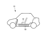
- FIG. 1 is a diagram showing a state in which the battery module according to the present embodiment is mounted on an electric vehicle
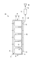
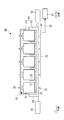
- FIG. 2 is a longitudinal sectional view of the battery module according to the present embodiment
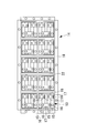
- FIG. 3 is a diagram showing the battery module according to the present embodiment.
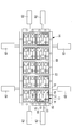
- FIG. 6 is a plan view showing a state where an upper housing is removed.
- the battery module 10 according to the present embodiment is mounted, for example, under a seat 12 in the center of a vehicle body of an electric vehicle (moving body) 11.
- the battery module 10 accommodates a plurality (10 in this embodiment) of assembled batteries 13 used as a power source for an electric vehicle 11 (see FIG. 1), and these assembled batteries 13. And a unit battery container (battery storage container) 14 for storing.
- the assembled battery 13 is formed by connecting (combining) a plurality of unit cells 15 (four in the present embodiment) such as lithium ion secondary batteries that are chargeable / dischargeable formed in a cubic shape in series,
- the positive electrode terminal 16 and the negative electrode terminal 16 of the adjacent unit cell 15 are electrically connected by a bus bar (connection bar) 17 formed of a conductive material.
- the unit battery case 14 includes an upper half casing 18 that is a lid, and a lower half casing 19 on which the assembled battery 13 is placed. As shown in FIG. 2, a female screw hole (not shown) penetrating in the plate thickness direction is formed in the upper half housing 18 at a position facing the central portion of the upper surface (top surface) of each unit cell 15. A holding screw 20 is screwed into (attached to) each female screw hole.
- the lower half housing 19 is provided with a bottom support 21 that supports the lower surface of the unit cell 15 at a position facing the lower surface (bottom) peripheral portion (or corner) of each unit cell 15.
- a partition wall (partition wall) 22 is provided between the assembled battery 13 adjacent to each other in the longitudinal direction and the assembled battery 13 adjacent to each other in the longitudinal direction. Further, a through hole (not shown) penetrating in the plate thickness direction is formed in the lower half housing 19 at a position facing the lower surface central portion of each assembled battery 13.
- Tubes 23 are connected to each other.
- the branch pipe 23 includes a liquid leakage detection sensor (for example, an optical liquid leakage sensor) 24 at one end, and is connected to a single main pipe 25 that extends straight in the horizontal direction. Is connected to a liquid leakage detection device 27 via a signal cable 26.
- the assembled battery 13 is accommodated in a sealed space formed in the unit battery container 14, and the electrolyte solution leaking from the unit cell 15 is contained in the lower half housing.
- the liquid leak detection sensor 24 After being guided to the main pipe 25 through the corresponding through hole formed in the body 19 and the branch pipe 23, it is led to the liquid leak detection sensor 24 through the main pipe 25.
- the liquid leak detection sensor 24 detects electrolyte solution, the liquid leak detection apparatus 27 will act
- the assembled battery 13 is pressed by a holding screw 20 and is fixed in the unit battery container 14, and a partition wall 22 is provided between the assembled battery 13 and the assembled battery 13, and the assembled battery 13 and the assembled battery 13 are assembled.
- a predetermined gap is secured between the battery 13 and the assembled batteries 13 or the single cells 15 can be prevented from colliding with each other, and the single cells 15 can be prevented from being damaged.
- FIG. 4 is a longitudinal sectional view of the battery module according to this embodiment.
- the battery module 40 according to this embodiment is different from that of the first embodiment described above in that a main pipe 41 is provided instead of the main pipe 25. Since other components are the same as those of the first embodiment described above, description of these components is omitted here.
- the main pipe 41 is a single straight pipe that is inclined so that one end portion provided with the liquid leak detection sensor 24 is positioned below the other end portion, and is connected to the main pipe via the branch pipe 23.
- the liquid introduced into the liquid 41 naturally flows toward the liquid leakage detection sensor 24.
- the main pipe 41 is disposed obliquely, and the electrolyte leaked from the unit cell 15 passes through the main pipe 41 and quickly toward the liquid leak detection sensor 24. Since it is guided (in a short time), even when a small amount of the electrolyte leaks from the unit cell 15, the liquid leak can be detected quickly and reliably, and the mobile body such as the electric vehicle 11 can be detected. The safety when mounted can be further improved.
- FIG. 5 is a longitudinal sectional view of the battery module according to this embodiment.
- the battery module 45 according to the present embodiment is different from that of the first embodiment described above in that a speaker (sound device: alarm device) 46 is provided. Since other components are the same as those of the first embodiment described above, description of these components is omitted here.
- the speaker 46 is connected to the liquid leakage detection device 27 via the signal cable 47.
- the liquid leakage detection sensor 24 detects liquid leakage
- the liquid leakage detection device 27 is activated and the speaker 46 emits an alarm sound.
- the passenger of the electric vehicle 11 (see FIG. 1) is informed of the liquid leak.
- the battery module 45 it is possible to grasp (know) the liquid leakage by hearing, so that the liquid leakage can be easily grasped even during driving and is mounted on a moving body such as the electric vehicle 11.
- the safety of the case can be further improved.
- FIG. 6 is a longitudinal sectional view of the battery module according to this embodiment.
- the battery module 50 according to the present embodiment is different from that of the first embodiment described above in that a fire extinguishing system (fire extinguishing device) 51 is provided. Since other components are the same as those of the first embodiment described above, description of these components is omitted here.
- the fire extinguishing system 51 includes a temperature sensor 52, a controller (controller) 53, a control valve 54, and a cylinder 55.
- the temperature sensor 52 is installed inside the ceiling surface of the upper half housing 18 and detects the internal temperature of the unit battery container 14, and is connected to the controller 53 via a signal cable 56.
- the temperature data detected by the temperature sensor 52 is constantly (sequentially) output to the controller 53 via the signal cable 56.
- the controller 53 sends a control signal (command) to the control valve 54 connected via the signal cable 57. Signal).
- the control valve 54 has one end connected to a through hole (not shown) penetrating the upper side wall of the upper half housing 18 in the plate thickness direction and communicating with the inside of the unit battery container 14, and the other end being a cylinder.
- the automatic open / close valve is connected to the middle of a pipe 58 connected to 55 and communicating with the inside of the cylinder 55. Further, when the control valve 54 senses a control signal sent from the controller 53, the control valve 54 rotates (or moves) from the fully closed position to the fully opened position. Yes.
- the inside of the cylinder 55 is filled with a fire extinguisher (powder extinguishing agent, carbon dioxide gas, etc.), and the fire extinguishing agent in the cylinder 55 is released into the unit battery container 14 vigorously by opening the control valve 54. It has come to be.
- a fire extinguisher pellet extinguishing agent, carbon dioxide gas, etc.
- the fire extinguisher filled in the cylinder 55 is discharged.
- the unit battery case 14 is expelled to the inside.
- the fire can be quickly and reliably extinguished and mounted on a moving body such as the electric vehicle 11. In this case, the safety can be further improved.
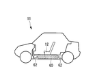
- FIG. 7 is a view showing a state where the battery module according to the present embodiment is mounted on an electric vehicle
- FIG. 8 is a view showing the battery module according to the present embodiment, and is a plan view showing a state where an upper housing is removed.
- FIG. 9 is a longitudinal sectional view of the battery module according to this embodiment.
- the battery module 60 according to the present embodiment is different from that of the first embodiment described above in that it includes a unit battery container installation base 61 and a shock absorber 62. Since other components are the same as those of the first embodiment described above, description of these components is omitted here.
- the unit battery container mounting base 61 accommodates the lower half housing 19 of the unit battery container 14 in close contact with each other, and two shock absorbers 62 are provided on each of the front, rear, left and right side walls. They are connected (coupled) one by one.
- the unit battery container mounting base 61 is formed with a through hole penetrating in the plate thickness direction at a position facing the through hole formed in the lower half housing 19.
- the shock absorber 62 is a device for buffering vibrations and shocks by a spring or the like and suppressing the movement of the unit battery container installation base 61 and the unit battery container 14 relative to the electric vehicle 11, and one end portion of the shock absorber 62 is a unit battery container installation base 61. The other end is connected (coupled) to a frame (not shown) of the electric vehicle 11 or the like.
- vibrations and shocks are passively buffered (absorbed) by the shock absorber 62, and collision between the assembled batteries 13 or the single cells 15 is prevented. Since the battery cell 15 can be prevented from being damaged, the safety when mounted on a moving body such as the electric vehicle 11 can be further improved.
- FIG. 10 is a longitudinal sectional view of the battery module according to the present embodiment.
- the battery module 65 according to this embodiment includes the fifth shock absorber described above in that it includes an impact mitigation system (impact mitigation device) 66 and a shock absorber 67 instead of the shock absorber 62.
- the battery module 65 according to this embodiment includes the fifth shock absorber described above in that it includes an impact mitigation system (impact mitigation device) 66 and a shock absorber 67 instead of the shock absorber 62.
- impact mitigation system impact mitigation device
- the impact relaxation system 66 includes an impact sensor (acceleration sensor) 68 and a controller (controller) 69.
- the impact sensor 68 is installed outside the ceiling surface of the upper half housing 18, and detects the impact or acceleration received by the unit battery container mounting base 61 and the unit battery container 14, and is connected to the controller 69 via the signal cable 70. It is connected to the.
- the impact data (acceleration data) detected by the impact sensor 68 is constantly (sequentially) output to the controller 69 via the signal cable 70.
- the controller 69 outputs a control signal (command signal) to the shock absorber 67 connected via the signal cable 71 based on the impact force (acceleration) detected by the impact sensor 68, and actively controls the shock absorber 67. To do.
- the shock absorber 67 is actively controlled based on a control signal sent from the controller 69 (controlled in a direction to mitigate an impact received by the unit battery container mounting base 61 and the unit battery container 14 or a direction to reduce an acceleration).
- a control signal sent from the controller 69 controlled in a direction to mitigate an impact received by the unit battery container mounting base 61 and the unit battery container 14 or a direction to reduce an acceleration.
- two each are disposed between the front, rear, left and right side walls of the unit battery container mounting base 61 and the frame (not shown) of the electric vehicle 11.
- the shock absorber 67 is actively controlled based on the impact force (acceleration) detected by the impact sensor 68, and the shock absorber 67 causes vibration and impact. It is designed to be actively buffered (absorbed). As a result, the collision between the assembled batteries 13 or the single cells 15 can be further prevented, and the damage of the single cells 15 can be further prevented. Can be further improved.
- FIG. 11 is a diagram illustrating a state where the battery module according to the present embodiment is mounted on an electric vehicle
- FIG. 12 is a diagram illustrating the battery module according to the present embodiment, and is a plan view illustrating a state where an upper housing is removed.
- 13 is a longitudinal sectional view of the battery module according to the present embodiment
- FIG. 14 is a view showing the battery module according to the present embodiment, and is a plan view showing a state in which the airbag system is operated
- FIG. 15 is the present embodiment. It is a figure which shows the battery module which concerns on a form, Comprising: It is a longitudinal cross-sectional view which shows the state which the air bag system act
- the battery module 75 includes a unit battery container 14 a, a unit battery container installation base 61 a, a suspension 76, an airbag system (an airbag device) instead of the unit battery container 14. ) 77 is different from that of the first embodiment described above. Since other components are the same as those of the first embodiment described above, description of these components is omitted here.
- the unit battery case 14a includes an upper half casing 18 that is a lid, and a lower half casing 19a on which the assembled battery 13 is placed.
- a female screw hole (not shown) penetrating in the plate thickness direction is formed in the upper half housing 18 at a position facing the central portion of the upper surface (top surface) of each unit cell 15.
- the presser screw 20 is screwed (attached).
- the lower half housing 19a is provided with a bottom support 21 that supports the lower surface of the unit cell 15 at a position facing the lower surface (bottom) peripheral edge (or corner) of each unit cell 15.
- a partition wall (partition wall) 22 is provided between the assembled battery 13 adjacent to each other in the longitudinal direction and the assembled battery 13 adjacent to each other in the longitudinal direction.
- the through hole described in the first embodiment is not formed in the lower half casing 19a, and the lower half casing 19a has the branch described in the first embodiment.
- the pipe 23, the liquid leak detection sensor 24, the main pipe 25, the signal cable 26, and the liquid leak detection device 27 are not provided.
- the unit battery container installation base 61a accommodates the lower half casing 19a of the unit battery container 14a in a close contact state.
- the through hole described in the fifth embodiment is not formed in the unit battery container mounting base 61a.
- the suspension 76 is a device for buffering vibrations and shocks by the plurality of springs 78 and the plurality of dampers 79 and suppressing the movement of the unit battery container mounting base 61a and the unit battery container 14 with respect to the electric vehicle 11.
- the upper end portion of the damper 79 is connected to the outside of the bottom surface of the unit battery container mounting base 61a, and the lower end portion is connected (coupled) to the frame 80 of the electric vehicle 11 or the like.
- the airbag system 77 includes an impact sensor (acceleration sensor) 81, a controller (controller) 82, and a plurality (four in this embodiment) of airbag storage boxes 83.
- the impact sensor 81 is installed on a frame (not shown) or the like of the electric vehicle 11 and detects an impact or acceleration received by the electric vehicle 11 (that is, the unit battery container mounting base 61 and the unit battery container 14). It is connected to the controller 82 via a signal cable 84.
- the impact data (acceleration data) detected by the impact sensor 81 is constantly (sequentially) output to the controller 82 via the signal cable 84.
- the controller 82 When the impact force (acceleration) detected by the impact sensor 81 exceeds a predetermined value (for example, 30G), the controller 82 is connected via the signal cable 85 and is accommodated inside each airbag storage box 83. A control signal (command signal) is output to the gas cylinder 86.
- a predetermined value for example, 30G
- the gas cylinder 86 is filled with compressed gas (nitrogen gas or the like), and the control signal is input to the gas cylinder 86 so that the gas in the gas cylinder 86 is accommodated in the airbag storage box 83.
- the bag body 87 is vigorously discharged into the bag body 87, and as shown in FIGS. 14 and 15, the bag body 87 is inflated instantaneously.
- the battery module 75 when the impact force (acceleration) detected by the impact sensor 81 exceeds a predetermined value (for example, 30 G), the gas filled in the gas cylinder 86 is stored in the airbag storage box. 83 is expelled to the inside of the bag body 87 accommodated inside 83. Thereby, the collision force between the battery module 75 and the vehicle body of the electric vehicle 11 is buffered (absorbed), and the collision between the assembled batteries 13 or the single cells 15 at the time of the collision can be prevented. Therefore, the safety when mounted on a moving body such as the electric vehicle 11 can be further improved.
- a predetermined value for example, 30 G
- the present invention is not limited to the above-described embodiment, and can be implemented by combining the above-described embodiments without departing from the gist of the present invention, and can be implemented by changing or modifying each embodiment. You can also
- Battery module 11 electric vehicle (mobile) 13 Battery assembly 14 Unit battery container 14a Unit battery container 18 Upper half casing 19 Lower half casing 19a Lower half casing 20 Holding screw 22 Bulkhead 23 Branch pipe 24 Liquid leak detection sensor 25 Main pipe 26 Signal cable 27 Liquid Leak detection device 40 Battery module 41 Main tube 45 Battery module 46 Speaker (acoustic device) 50 battery module 51 fire extinguishing system 60 battery module 61 unit battery container installation base 61a unit battery container installation base 62 shock absorber 65 battery module 66 impact mitigation system 67 shock absorber 68 impact sensor 75 battery module 77 airbag system 81 impact sensor 83 airbag Storage box 87 bag
Abstract
Description
本発明の第1の態様に係る電池モジュールは、複数個の組電池と、これら組電池を収容するユニット電池容器とを備えた電池モジュールであって、前記ユニット電池容器が、蓋体である上半部筐体と、前記組電池が載置される下半部筐体とを備えてなり、前記下半部筐体には、各組電池の下面中央部と対向する位置に、板厚方向に貫通する貫通穴が形成され、各貫通穴には枝管がそれぞれ接続されており、これら枝管は、一端部に液漏れ検知センサを備えた1本の本管に接続され、前記液漏れ検知センサは、信号ケーブルを介して液漏れ検知装置に接続されている電池モジュールである。
これにより、電気自動車等の移動体に搭載した場合でも、安全性を確保することができる。
これにより、組電池を構成する単電池から漏れ出た電解液に引火して、ユニット電池容器内で火災が発生した場合でも、迅速かつ確実に消火することができて、電気自動車等の移動体に搭載した場合の安全性をさらに向上させることができる。
これにより、組電池同士あるいは組電池を構成する単電池同士の衝突をさらに防止することができ、単電池の破損をさらに防止することができて、電気自動車等の移動体に搭載した場合の安全性をさらに向上させることができる。
これにより、電池モジュールに加わる衝突力が緩衝され(吸収され)衝突時における組電池同士あるいは組電池を構成する単電池同士の衝突を防止することができ、単電池の破損を防止することができて、電気自動車等の移動体に搭載した場合の安全性をさらに向上させることができる。
図1は本実施形態に係る電池モジュールが電気自動車に搭載された状態を示す図、図2は本実施形態に係る電池モジュールの縦断面図、図3は本実施形態に係る電池モジュールを示す図であって、上部筐体を外した状態を示す平面図である。
図1に示すように、本実施形態に係る電池モジュール10は、例えば、電気自動車(移動体)11の車体中央部の座席12の下に搭載される。
組電池13は、立方体状に形成された充放電可能なリチウムイオン二次電池等の単電池15が複数個(本実施形態では4個)直列に接続された(組み合わされた)ものであり、隣接する単電池15の正極と負極の電極端子16は、導電性を有する材料で形成されたブスバー(接続バー)17により電気的に接続されている。
図2に示すように、上半部筐体18には、各単電池15の上面(頂面)中央部と対向する位置に、板厚方向に貫通する雌ねじ穴(図示せず)が形成されており、各雌ねじ穴には押さえねじ20が螺合している(取り付けられている)。
また、下半部筐体19には、各組電池13の下面中央部と対向する位置に、板厚方向に貫通する貫通穴(図示せず)が形成されており、各貫通穴には枝管23がそれぞれ接続されている。枝管23は、一端部に液漏れ検知センサ(例えば、光学式の漏液センサ)24を備え、かつ、水平方向に真っ直ぐ延びる1本の本管25に接続されており、液漏れ検知センサ24は、信号ケーブル26を介して液漏れ検知装置27に接続されている。
図4に示すように、本実施形態に係る電池モジュール40は、本管25の代わりに、本管41を備えているという点で上述した第1実施形態のものと異なる。その他の構成要素については上述した第1実施形態のものと同じであるので、ここではそれら構成要素についての説明は省略する。
図5に示すように、本実施形態に係る電池モジュール45は、スピーカー(音響装置:発報装置)46を備えているという点で上述した第1実施形態のものと異なる。その他の構成要素については上述した第1実施形態のものと同じであるので、ここではそれら構成要素についての説明は省略する。
図6に示すように、本実施形態に係る電池モジュール50は、消火システム(消火装置)51を備えているという点で上述した第1実施形態のものと異なる。その他の構成要素については上述した第1実施形態のものと同じであるので、ここではそれら構成要素についての説明は省略する。
温度センサ52は、上半部筐体18の天井面内側に設置され、ユニット電池容器14の内部温度を検知するものであり、信号ケーブル56を介してコントローラ53に接続されている。そして、温度センサ52で検知された温度データは、信号ケーブル56を介してコントローラ53に常時(逐次)出力されるようになっている。
コントローラ53は、温度センサ52で検知されたユニット電池容器14の内部温度が所定の値(例えば、100℃)を超えたら、信号ケーブル57を介して接続されている制御弁54に制御信号(指令信号)を出力するものである。
これにより、単電池15から漏れ出た電解液に引火して、ユニット電池容器14内で火災が発生した場合でも、迅速かつ確実に消火することができて、電気自動車11等の移動体に搭載した場合の安全性をさらに向上させることができる。
図7は本実施形態に係る電池モジュールが電気自動車に搭載された状態を示す図、図8は本実施形態に係る電池モジュールを示す図であって、上部筐体を外した状態を示す平面図、図9は本実施形態に係る電池モジュールの縦断面図である。
図7から図9に示すように、本実施形態に係る電池モジュール60は、ユニット電池容器設置台61およびショックアブソーバー62を備えているという点で上述した第1実施形態のものと異なる。その他の構成要素については上述した第1実施形態のものと同じであるので、ここではそれら構成要素についての説明は省略する。
図10に示すように、本実施形態に係る電池モジュール65は、ショックアブソーバー62の代わりに、衝撃緩和システム(衝撃緩和装置)66と、ショックアブソーバー67とを備えているという点で上述した第5実施形態のものと異なる。その他の構成要素については上述した第5実施形態のものと同じであるので、ここではそれら構成要素についての説明は省略する。
衝撃センサ68は、上半部筐体18の天井面外側に設置され、ユニット電池容器設置台61およびユニット電池容器14が受ける衝撃または加速度を検出するものであり、信号ケーブル70を介してコントローラ69に接続されている。そして、衝撃センサ68で検知された衝撃データ(加速度データ)は、信号ケーブル70を介してコントローラ69に常時(逐次)出力されるようになっている。
コントローラ69は、衝撃センサ68で検知された衝撃力(加速度)に基づいて、信号ケーブル71を介して接続されているショックアブソーバー67に制御信号(指令信号)を出力し、ショックアブソーバー67をアクティブ制御するものである。
これにより、組電池13同士あるいは単電池15同士の衝突をさらに防止することができ、単電池15の破損をさらに防止することができて、電気自動車11等の移動体に搭載した場合の安全性をさらに向上させることができる。
図11は本実施形態に係る電池モジュールが電気自動車に搭載された状態を示す図、図12は本実施形態に係る電池モジュールを示す図であって、上部筐体を外した状態を示す平面図、図13は本実施形態に係る電池モジュールの縦断面図、図14は本実施形態に係る電池モジュールを示す図であって、エアバックシステムが作動した状態を示す平面図、図15は本実施形態に係る電池モジュールを示す図であって、エアバックシステムが作動した状態を示す縦断面図である。
上半部筐体18には、各単電池15の上面(頂面)中央部と対向する位置に、板厚方向に貫通する雌ねじ穴(図示せず)が形成されており、各雌ねじ穴には押さえねじ20が螺合している(取り付けられている)。
なお、本実施形態において、下半部筐体19aには、第1実施形態のところで説明した貫通穴は形成されておらず、下半部筐体19aは、第1実施形態のところで説明した枝管23、液漏れ検知センサ24、本管25、信号ケーブル26および液漏れ検知装置27を備えていない。
なお、本実施形態において、ユニット電池容器設置台61aには、第5実施形態のところで説明した貫通穴は形成されていない。
衝撃センサ81は、電気自動車11のフレーム(図示せず)等に設置され、電気自動車11(すなわち、ユニット電池容器設置台61およびユニット電池容器14)が受ける衝撃または加速度を検出するものであり、信号ケーブル84を介してコントローラ82に接続されている。そして、衝撃センサ81で検知された衝撃データ(加速度データ)は、信号ケーブル84を介してコントローラ82に常時(逐次)出力されるようになっている。
コントローラ82は、衝撃センサ81で検知された衝撃力(加速度)が所定の値(例えば、30G)を超えたら、信号ケーブル85を介して接続され、各エアバック格納箱83の内部に収容されているガスボンベ86に制御信号(指令信号)を出力するものである。
これにより、電池モジュール75と電気自動車11の車体との衝突力が緩衝され(吸収され)衝突時における組電池13同士あるいは単電池15同士の衝突を防止することができ、単電池15の破損を防止することができて、電気自動車11等の移動体に搭載した場合の安全性をさらに向上させることができる。
11 電気自動車(移動体)
13 組電池
14 ユニット電池容器
14a ユニット電池容器
18 上半部筐体
19 下半部筐体
19a 下半部筐体
20 押さえねじ
22 隔壁
23 枝管
24 液漏れ検知センサ
25 本管
26 信号ケーブル
27 液漏れ検知装置
40 電池モジュール
41 本管
45 電池モジュール
46 スピーカー(音響装置)
50 電池モジュール
51 消火システム
60 電池モジュール
61 ユニット電池容器設置台
61a ユニット電池容器設置台
62 ショックアブソーバー
65 電池モジュール
66 衝撃緩和システム
67 ショックアブソーバー
68 衝撃センサ
75 電池モジュール
77 エアバックシステム
81 衝撃センサ
83 エアバック格納箱
87 袋体
Claims (10)
- 複数個の組電池と、これら組電池を収容するユニット電池容器とを備えた電池モジュールであって、
前記ユニット電池容器が、蓋体である上半部筐体と、前記組電池が載置される下半部筐体とを備えてなり、
前記下半部筐体には、各組電池の下面中央部と対向する位置に、板厚方向に貫通する貫通穴が形成され、各貫通穴には枝管がそれぞれ接続されており、これら枝管は、一端部に液漏れ検知センサを備えた1本の本管に接続され、前記液漏れ検知センサは、信号ケーブルを介して液漏れ検知装置に接続されている電池モジュール。 - 前記本管は、前記液漏れ検知センサを備えた一端部が、他端部よりも下方に位置するように傾斜して配置された1本の直管である請求項1に記載の電池モジュール。
- 前記液漏れ検知装置には、音響装置が接続されており、前記液漏れ検知センサが液漏れを検知すると、前記液漏れ検知装置が作動して、前記音響装置が警報音を発する請求項1または2に記載の電池モジュール。
- 前記ユニット電池容器の内部温度が所定の値を超えたら、前記ユニット電池容器の内部に消火剤を放出させる消火システムを備えている請求項1から3のいずれか一項に記載の電池モジュール。
- 前記下半部筐体を密着した状態で収容するユニット電池容器設置台と、このユニット電池容器設置台の側壁に取り付けられて振動や衝撃を吸収するショックアブソーバーとを備えている請求項1から4のいずれか一項に記載の電池モジュール。
- 前記ユニット電池容器に取り付けられた衝撃センサで検知された衝撃力に基づいて、前記ショックアブソーバーをアクティブに制御する衝撃緩和システムを備えている請求項5に記載の電池モジュール。
- 複数個の組電池と、これら組電池を収容するユニット電池容器とを備えた電池モジュールであって、
前記ユニット電池容器が、蓋体である上半部筐体と、前記組電池が載置される下半部筐体とを備えてなり、
前記ユニット電池容器の周囲に、衝撃センサで検知された衝撃力が所定の値を超えたら、エアバック格納箱の内部に収容された袋体の内部にガスを放出させるエアバックシステムが配置されている電池モジュール。 - 前記上半部筐体には、各組電池の上面を押さえつける押さえねじが取り付けられている請求項1から7のいずれか一項に記載の電池モジュール。
- 前記下半部筐体には、隣接する組電池と組電池とを仕切る隔壁が設けられている請求項1から8のいずれか一項に記載の電池モジュール。
- 請求項1から9のいずれか一項に記載の電池モジュールを具備してなる移動体。
Priority Applications (4)
| Application Number | Priority Date | Filing Date | Title |
|---|---|---|---|
| KR1020117012334A KR101278015B1 (ko) | 2008-12-24 | 2009-10-26 | 전지 모듈 |
| US13/132,029 US20110250477A1 (en) | 2008-12-24 | 2009-10-26 | Battery module |
| EP09834614.1A EP2369656A4 (en) | 2008-12-24 | 2009-10-26 | BATTERY MODULE |
| CN2009801480323A CN102227831A (zh) | 2008-12-24 | 2009-10-26 | 电池组件 |
Applications Claiming Priority (2)
| Application Number | Priority Date | Filing Date | Title |
|---|---|---|---|
| JP2008-328023 | 2008-12-24 | ||
| JP2008328023A JP4786700B2 (ja) | 2008-12-24 | 2008-12-24 | 電池モジュール |
Publications (1)
| Publication Number | Publication Date |
|---|---|
| WO2010073809A1 true WO2010073809A1 (ja) | 2010-07-01 |
Family
ID=42287433
Family Applications (1)
| Application Number | Title | Priority Date | Filing Date |
|---|---|---|---|
| PCT/JP2009/068323 WO2010073809A1 (ja) | 2008-12-24 | 2009-10-26 | 電池モジュール |
Country Status (6)
| Country | Link |
|---|---|
| US (1) | US20110250477A1 (ja) |
| EP (1) | EP2369656A4 (ja) |
| JP (1) | JP4786700B2 (ja) |
| KR (1) | KR101278015B1 (ja) |
| CN (1) | CN102227831A (ja) |
| WO (1) | WO2010073809A1 (ja) |
Cited By (6)
| Publication number | Priority date | Publication date | Assignee | Title |
|---|---|---|---|---|
| WO2012019972A1 (de) * | 2010-08-13 | 2012-02-16 | Robert Bosch Gmbh | Batteriegehäuse mit beschleunigungssensitiven elementen, batterie sowie kraftfahrzeug mit batterie |
| WO2012028237A1 (de) * | 2010-08-31 | 2012-03-08 | Li-Tec Battery Gmbh | Transportvorrichtung für elektrochemische energiespeichervorrichtungen |
| EP2505459A1 (en) * | 2011-03-31 | 2012-10-03 | Mitsubishi Jidosha Kogyo Kabushiki Kaisha | Battery installation structure for electric vehicles |
| CN103782444A (zh) * | 2011-09-08 | 2014-05-07 | 株式会社Lg化学 | 电池组灭火装置 |
| CN110383029A (zh) * | 2017-08-18 | 2019-10-25 | 株式会社Lg化学 | 通过使用陀螺传感器和湿度检测传感器来检测到电池组中的液体泄漏的装置和方法 |
| WO2020006503A1 (en) * | 2018-06-28 | 2020-01-02 | Luis Perez | Fire suppressant enclosures for battery cell systems |
Families Citing this family (57)
| Publication number | Priority date | Publication date | Assignee | Title |
|---|---|---|---|---|
| GB2475326A (en) * | 2009-11-16 | 2011-05-18 | Autoliv Dev | Inflatable battery protector |
| WO2012014348A1 (ja) * | 2010-07-28 | 2012-02-02 | パナソニック株式会社 | 電池モジュール及び電池パック |
| CA2854678C (en) | 2011-11-07 | 2017-07-18 | Aleees Eco Ark Co. Ltd. | Abnormal battery detecting system and abnormal battery detecting method for battery module |
| DE102011122058A1 (de) * | 2011-12-22 | 2013-06-27 | Andreas Stihl Ag & Co. Kg | "Rückentragbarer Akkupack" |
| CN103208656B (zh) * | 2012-01-16 | 2016-03-30 | 微宏动力系统(湖州)有限公司 | 电池组系统及其漏液检测方法 |
| CN103208598B (zh) | 2012-01-16 | 2016-06-29 | 微宏动力系统(湖州)有限公司 | 电池组及其漏液检测方法 |
| DE102012001596A1 (de) | 2012-01-26 | 2013-08-01 | Daimler Ag | Fahrzeug mit einer Batterie |
| ITBO20120056A1 (it) | 2012-02-07 | 2013-08-08 | Ferrari Spa | Sistema di accumulo di energia elettrica per un veicolo con propulsione elettrica e presentante una struttura priva di linee di resistenza longitudinali o trasversali |
| ITBO20120057A1 (it) | 2012-02-07 | 2013-08-08 | Ferrari Spa | Sistema di accumulo di energia elettrica per un veicolo con propulsione elettrica e presentante batteria chimiche cilindriche annegate in una matrice di supporto |
| DE102012003017A1 (de) * | 2012-02-15 | 2013-08-22 | Key Safety Systems, Inc. | Brandvorbeugung oder Brandbeseitigung in einem elektrochemischen Energiespeicher |
| ITBO20120184A1 (it) * | 2012-04-06 | 2013-10-07 | Ferrari Spa | Sistema di accumulo di energia elettrica per un veicolo con propulsione elettrica e presentante batterie chimiche cilindriche inserite in una matrice di supporto plastica |
| US20170043194A1 (en) * | 2012-04-10 | 2017-02-16 | Greg Ling | Integrated thermal event suppression system |
| JP5857882B2 (ja) | 2012-05-31 | 2016-02-10 | 富士通株式会社 | 決定装置、決定プログラムおよび決定方法 |
| DE102012011061A1 (de) * | 2012-06-04 | 2013-12-05 | Li-Tec Battery Gmbh | Energieversorgungsvorrichtung mit einer ersten Leistung sowie Verfahren zum Betrieb dieser Energieversorgungsvorrichtung |
| US9853330B2 (en) * | 2012-07-10 | 2017-12-26 | GM Global Technology Operations LLC | Enhanced conductive fluid sensor for HV liquid cooled battery packs |
| US8865333B2 (en) * | 2012-07-17 | 2014-10-21 | GM Global Technology Operations LLC | Systems and methods for mitigating battery damage caused by coolant leaks |
| JP2014024518A (ja) * | 2012-07-30 | 2014-02-06 | Toyota Motor Corp | 電源装置の取付構造および車両 |
| KR101489837B1 (ko) * | 2012-11-19 | 2015-02-04 | 자동차부품연구원 | 리튬이온 배터리 화재 방지 장치 및 방법 |
| KR101986083B1 (ko) * | 2012-12-27 | 2019-06-05 | 에스케이이노베이션 주식회사 | 배터리 팩 |
| CN103943909B (zh) * | 2013-01-17 | 2017-02-22 | 微宏动力系统(湖州)有限公司 | 电池组系统 |
| CN103972436B (zh) * | 2013-02-04 | 2016-02-10 | 能元科技股份有限公司 | 电池防护装置及电池阵列 |
| FR3007209B1 (fr) * | 2013-06-18 | 2015-07-03 | Peugeot Citroen Automobiles Sa | Dispositif anti-incendie autonome pour une batterie a cellule(s) de stockage |
| WO2015002541A1 (en) * | 2013-07-05 | 2015-01-08 | Van Peperzeel Services B.V. | Use of vitrifying compositions for electric battery fire prevention or extinguishing |
| CN103579702B (zh) * | 2013-11-21 | 2016-01-06 | 奇瑞新能源汽车技术有限公司 | 一种防止电池包内部积液的系统及其控制方法 |
| US9520619B2 (en) | 2013-11-27 | 2016-12-13 | The Boeing Company | Methods of inerting lithium-containing batteries and associated containers |
| FR3016086B1 (fr) * | 2013-12-26 | 2017-12-22 | Commissariat Energie Atomique | Batterie electrochimique a securite de fonctionnement amelioree en environnement humide |
| KR102246772B1 (ko) * | 2014-04-23 | 2021-04-30 | 삼성에스디아이 주식회사 | 배터리 팩 |
| KR101584295B1 (ko) * | 2014-07-03 | 2016-01-25 | 인셀(주) | 랙 구조를 갖는 배터리 시스템 |
| US9818995B2 (en) | 2014-07-07 | 2017-11-14 | Microvast Power Systems Co., Ltd. | Battery pack system |
| EP3051607B1 (en) | 2015-01-29 | 2018-01-03 | Volvo Car Corporation | Inflatable structure for battery protection |
| AU2017201690B2 (en) * | 2016-03-14 | 2022-09-15 | The Raymond Corporation | Battery counterweight system |
| TWI811718B (zh) | 2016-03-16 | 2023-08-11 | 澳門商創科(澳門離岸商業服務)有限公司 | 具有無線通訊的電動工具蓄電池組 |
| CN106410308B (zh) * | 2016-11-29 | 2023-10-20 | 华霆(合肥)动力技术有限公司 | 检漏报警装置、方法及电池模组 |
| CN106585354A (zh) * | 2016-12-23 | 2017-04-26 | 苏州精控能源科技有限公司 | 一种电动汽车的撞击处理装置及方法 |
| KR102220902B1 (ko) | 2017-01-26 | 2021-02-26 | 삼성에스디아이 주식회사 | 소화시스템을 포함하는 배터리 팩 |
| US10777856B2 (en) | 2017-06-19 | 2020-09-15 | Dura Operating, Llc | Safety sensor module with vehicle communication to first responders |
| US10707538B2 (en) | 2017-06-19 | 2020-07-07 | Dura Operating, Llc | Safety sensor module with vehicle communication to first responders |
| TWI653456B (zh) * | 2017-08-23 | 2019-03-11 | 致茂電子股份有限公司 | 電池化成裝置及其針盤結構 |
| EP3716352B1 (en) * | 2017-11-22 | 2022-08-10 | TDK Corporation | Battery pack |
| JP6944649B2 (ja) * | 2018-03-19 | 2021-10-06 | トヨタ自動車株式会社 | 電動車両 |
| TWI666848B (zh) * | 2018-09-12 | 2019-07-21 | 財團法人工業技術研究院 | 蓄電系統消防裝置及其運作方法 |
| KR102090405B1 (ko) * | 2018-11-21 | 2020-03-18 | (주)알씨디에이치 | 누액감지 모니터링 기능을 갖는 대용량 리튬폴리머 배터리 시스템 |
| KR102090404B1 (ko) * | 2018-11-21 | 2020-03-18 | (주)알씨디에이치 | 누액 및 가스 검출을 기능을 갖는 대용량 리튬폴리머 배터리 장치 |
| CN109270199B (zh) * | 2018-11-21 | 2021-06-04 | 浙江福立分析仪器股份有限公司 | 一种液相色谱检测器及其除液方法 |
| KR101977136B1 (ko) * | 2019-02-21 | 2019-08-28 | 주식회사 에코이노 | 에너지저장장치 화재 사고 발생시 대응하는 방법 및 그를 이용한 장치 |
| KR20210017535A (ko) * | 2019-08-08 | 2021-02-17 | 주식회사 엘지화학 | 소화 유닛을 포함한 배터리 팩 |
| AT523189B1 (de) * | 2019-11-20 | 2021-11-15 | Evm Ag | Wechselbrückenaufbau, insbesondere vom Typ WAB, sowie Transportcontainer für elektrisch angetriebene Zugfahrzeuge mit zugeordnetem Batterieaufnahmefach |
| US20210218004A1 (en) * | 2020-01-10 | 2021-07-15 | Caterpillar Inc. | Battery fire suppression system |
| DE102020111569A1 (de) * | 2020-04-28 | 2021-10-28 | Audi Aktiengesellschaft | Warnsystem und Warnverfahren für ein Kraftfahrzeug mit einer Hochvoltbatterie |
| DE102020113082A1 (de) | 2020-05-14 | 2021-11-18 | Dr. Ing. H.C. F. Porsche Aktiengesellschaft | Vorrichtung und Verfahren für eine an einem Unterboden eines Fahrzeugs angeordnete Batterie |
| GB2595669B (en) | 2020-06-02 | 2024-04-24 | Aliaxis Uk Ltd | Dual Contained Pipe Scraper |
| KR20220055138A (ko) * | 2020-10-26 | 2022-05-03 | 주식회사 엘지에너지솔루션 | 전지 모듈 및 이를 포함하는 전지 팩 |
| CN113178652B (zh) * | 2021-04-13 | 2022-11-11 | 江苏华梓车业有限公司 | 电动汽车电池用保护装置 |
| DE102021114042A1 (de) | 2021-05-31 | 2022-12-01 | Bayerische Motoren Werke Aktiengesellschaft | Antriebsbatterie und Kraftfahrzeug |
| CN114734803A (zh) * | 2022-03-17 | 2022-07-12 | 盐城市步高汽配制造有限公司 | 电动汽车底盘集成模块系统 |
| CN116793405A (zh) * | 2023-08-29 | 2023-09-22 | 宁德时代新能源科技股份有限公司 | 检测装置、电池及用电装置 |
| CN117554838A (zh) * | 2024-01-11 | 2024-02-13 | 深圳市百耐信科技有限公司 | 一种工商业液冷储能电池组装设备及控制系统 |
Citations (3)
| Publication number | Priority date | Publication date | Assignee | Title |
|---|---|---|---|---|
| JP2007242593A (ja) | 2006-02-13 | 2007-09-20 | Nissan Motor Co Ltd | 電池モジュール、組電池及びそれらの電池を搭載した車両 |
| JP2007273353A (ja) * | 2006-03-31 | 2007-10-18 | Toyota Motor Corp | 電池構造 |
| JP2008060000A (ja) * | 2006-09-01 | 2008-03-13 | Sony Corp | 電池パックおよび電子機器 |
Family Cites Families (7)
| Publication number | Priority date | Publication date | Assignee | Title |
|---|---|---|---|---|
| JPH0974603A (ja) * | 1995-09-01 | 1997-03-18 | Mitsubishi Motors Corp | 電気自動車用バッテリの安全装置 |
| JP3349349B2 (ja) * | 1996-06-27 | 2002-11-25 | 三洋電機株式会社 | 組電池の取り付け構造 |
| GB9722890D0 (en) * | 1997-10-31 | 1998-01-07 | Brook Chrispin Kenneth | Battery charging rack |
| JP3914707B2 (ja) * | 2000-06-19 | 2007-05-16 | 本田技研工業株式会社 | 蓄電素子およびその保持構造 |
| CN1303721C (zh) * | 2004-02-25 | 2007-03-07 | 明基电通股份有限公司 | 具有剩余电量显示功能的电池与其方法 |
| JP4471915B2 (ja) * | 2005-09-28 | 2010-06-02 | 三洋電機株式会社 | 車両用の電源装置 |
| JP2008230519A (ja) * | 2007-03-22 | 2008-10-02 | Toyota Motor Corp | 燃料電池用ケース |
-
2008
- 2008-12-24 JP JP2008328023A patent/JP4786700B2/ja not_active Expired - Fee Related
-
2009
- 2009-10-26 EP EP09834614.1A patent/EP2369656A4/en not_active Withdrawn
- 2009-10-26 US US13/132,029 patent/US20110250477A1/en not_active Abandoned
- 2009-10-26 WO PCT/JP2009/068323 patent/WO2010073809A1/ja active Application Filing
- 2009-10-26 CN CN2009801480323A patent/CN102227831A/zh active Pending
- 2009-10-26 KR KR1020117012334A patent/KR101278015B1/ko not_active IP Right Cessation
Patent Citations (3)
| Publication number | Priority date | Publication date | Assignee | Title |
|---|---|---|---|---|
| JP2007242593A (ja) | 2006-02-13 | 2007-09-20 | Nissan Motor Co Ltd | 電池モジュール、組電池及びそれらの電池を搭載した車両 |
| JP2007273353A (ja) * | 2006-03-31 | 2007-10-18 | Toyota Motor Corp | 電池構造 |
| JP2008060000A (ja) * | 2006-09-01 | 2008-03-13 | Sony Corp | 電池パックおよび電子機器 |
Non-Patent Citations (1)
| Title |
|---|
| See also references of EP2369656A4 |
Cited By (13)
| Publication number | Priority date | Publication date | Assignee | Title |
|---|---|---|---|---|
| WO2012019972A1 (de) * | 2010-08-13 | 2012-02-16 | Robert Bosch Gmbh | Batteriegehäuse mit beschleunigungssensitiven elementen, batterie sowie kraftfahrzeug mit batterie |
| CN103180226A (zh) * | 2010-08-31 | 2013-06-26 | 锂电池科技有限公司 | 用于电化学能量存储设备的运输设备 |
| WO2012028237A1 (de) * | 2010-08-31 | 2012-03-08 | Li-Tec Battery Gmbh | Transportvorrichtung für elektrochemische energiespeichervorrichtungen |
| US9034502B2 (en) | 2011-03-31 | 2015-05-19 | Mitsubishi Jidosha Kogyo Kabushiki Kaisha | Battery installation structure for electric vehicles |
| JP2012214065A (ja) * | 2011-03-31 | 2012-11-08 | Mitsubishi Motors Corp | 電気自動車のバッテリ搭載構造 |
| EP2505459A1 (en) * | 2011-03-31 | 2012-10-03 | Mitsubishi Jidosha Kogyo Kabushiki Kaisha | Battery installation structure for electric vehicles |
| CN103782444A (zh) * | 2011-09-08 | 2014-05-07 | 株式会社Lg化学 | 电池组灭火装置 |
| EP2755275A4 (en) * | 2011-09-08 | 2015-08-05 | Lg Chemical Ltd | DEVICE FOR DELETING A BATTERY PACK BRAND |
| US9539448B2 (en) | 2011-09-08 | 2017-01-10 | Lg Chem, Ltd. | Fire suppression apparatus for a battery pack |
| CN110383029A (zh) * | 2017-08-18 | 2019-10-25 | 株式会社Lg化学 | 通过使用陀螺传感器和湿度检测传感器来检测到电池组中的液体泄漏的装置和方法 |
| CN110383029B (zh) * | 2017-08-18 | 2021-01-26 | 株式会社Lg化学 | 通过使用陀螺传感器和湿度检测传感器来检测到电池组中的液体泄漏的装置和方法 |
| WO2020006503A1 (en) * | 2018-06-28 | 2020-01-02 | Luis Perez | Fire suppressant enclosures for battery cell systems |
| US11349166B2 (en) | 2018-06-28 | 2022-05-31 | Luis Perez | Fire suppressant enclosures for battery cell systems and associated methods of modular operation |
Also Published As
| Publication number | Publication date |
|---|---|
| JP2010153117A (ja) | 2010-07-08 |
| KR20110079857A (ko) | 2011-07-08 |
| JP4786700B2 (ja) | 2011-10-05 |
| US20110250477A1 (en) | 2011-10-13 |
| EP2369656A4 (en) | 2014-02-12 |
| EP2369656A1 (en) | 2011-09-28 |
| KR101278015B1 (ko) | 2013-06-27 |
| CN102227831A (zh) | 2011-10-26 |
Similar Documents
| Publication | Publication Date | Title |
|---|---|---|
| JP4786700B2 (ja) | 電池モジュール | |
| KR102061872B1 (ko) | 이차전지 팩 케이스 및 이를 포함하는 이차전지 팩 | |
| JP5619154B2 (ja) | 電池パック | |
| US9806325B2 (en) | Battery housing for lithium-ion cells | |
| US10601088B2 (en) | Battery module endplate with sealed hole for cooling tube connection | |
| CN110235272B (zh) | 电池托盘盖、带盖电池托盘以及电池的制造方法 | |
| JP6279834B2 (ja) | 蓄電装置及びそれを使用する移動体又は施設 | |
| JP6042734B2 (ja) | 消火装置 | |
| JP6080201B2 (ja) | 消火装置及びこれを用いたエージング方法 | |
| US20090205846A1 (en) | Fire suppression system for an onboard electrical energy source | |
| WO2012014348A1 (ja) | 電池モジュール及び電池パック | |
| JPH1016689A (ja) | 組電池の取り付け構造 | |
| JP2014036714A (ja) | 電気自動車向け消火システム | |
| JP6231266B2 (ja) | 電気自動車向け消火システム | |
| US20190344109A1 (en) | Fire suppression system | |
| US20170113080A1 (en) | Fire prevention or fire extinguishing in an electrochemical energy storage system | |
| JP6103856B2 (ja) | 電気自動車向け消火システム | |
| JP2017060805A (ja) | 電気自動車向け消火システム | |
| JP6017221B2 (ja) | 電気自動車向け消火システム | |
| KR20210049079A (ko) | 배터리 모듈, 이러한 배터리 모듈을 포함하는 배터리 팩 및 이러한 배터리 팩을 포함하는 자동차 | |
| CN216536631U (zh) | 动力电池及两轮电动车 | |
| CN117813723A (zh) | 包括用于灭火的筒的电池模块 | |
| CN220585371U (zh) | 一种电池包 | |
| KR20220075553A (ko) | 전자기기 및 배터리용 소화장치 | |
| JP2024506958A (ja) | 安全性が強化されたバッテリーモジュールとバッテリーパック |
Legal Events
| Date | Code | Title | Description |
|---|---|---|---|
| WWE | Wipo information: entry into national phase |
Ref document number: 200980148032.3 Country of ref document: CN |
|
| 121 | Ep: the epo has been informed by wipo that ep was designated in this application |
Ref document number: 09834614 Country of ref document: EP Kind code of ref document: A1 |
|
| WWE | Wipo information: entry into national phase |
Ref document number: 2009834614 Country of ref document: EP |
|
| ENP | Entry into the national phase |
Ref document number: 20117012334 Country of ref document: KR Kind code of ref document: A |
|
| WWE | Wipo information: entry into national phase |
Ref document number: 13132029 Country of ref document: US |
|
| NENP | Non-entry into the national phase |
Ref country code: DE |