WO2010067591A1 - ラック・アンド・ピニオン機構、真空処理装置、ラック・アンド・ピニオン機構の駆動制御方法、駆動制御プログラム及び記録媒体 - Google Patents
ラック・アンド・ピニオン機構、真空処理装置、ラック・アンド・ピニオン機構の駆動制御方法、駆動制御プログラム及び記録媒体 Download PDFInfo
- Publication number
- WO2010067591A1 WO2010067591A1 PCT/JP2009/006716 JP2009006716W WO2010067591A1 WO 2010067591 A1 WO2010067591 A1 WO 2010067591A1 JP 2009006716 W JP2009006716 W JP 2009006716W WO 2010067591 A1 WO2010067591 A1 WO 2010067591A1
- Authority
- WO
- WIPO (PCT)
- Prior art keywords
- pinion
- rack
- gear
- pinion gear
- angle
- Prior art date
- Legal status (The legal status is an assumption and is not a legal conclusion. Google has not performed a legal analysis and makes no representation as to the accuracy of the status listed.)
- Ceased
Links
Images


Classifications
-
- H—ELECTRICITY
- H10—SEMICONDUCTOR DEVICES; ELECTRIC SOLID-STATE DEVICES NOT OTHERWISE PROVIDED FOR
- H10P—GENERIC PROCESSES OR APPARATUS FOR THE MANUFACTURE OR TREATMENT OF DEVICES COVERED BY CLASS H10
- H10P72/00—Handling or holding of wafers, substrates or devices during manufacture or treatment thereof
- H10P72/30—Handling or holding of wafers, substrates or devices during manufacture or treatment thereof for conveying, e.g. between different workstations
- H10P72/32—Handling or holding of wafers, substrates or devices during manufacture or treatment thereof for conveying, e.g. between different workstations between different workstations
- H10P72/3202—Mechanical details, e.g. rollers or belts
-
- B—PERFORMING OPERATIONS; TRANSPORTING
- B65—CONVEYING; PACKING; STORING; HANDLING THIN OR FILAMENTARY MATERIAL
- B65G—TRANSPORT OR STORAGE DEVICES, e.g. CONVEYORS FOR LOADING OR TIPPING, SHOP CONVEYOR SYSTEMS OR PNEUMATIC TUBE CONVEYORS
- B65G49/00—Conveying systems characterised by their application for specified purposes not otherwise provided for
- B65G49/05—Conveying systems characterised by their application for specified purposes not otherwise provided for for fragile or damageable materials or articles
- B65G49/06—Conveying systems characterised by their application for specified purposes not otherwise provided for for fragile or damageable materials or articles for fragile sheets, e.g. glass
- B65G49/061—Lifting, gripping, or carrying means, for one or more sheets forming independent means of transport, e.g. suction cups, transport frames
-
- C—CHEMISTRY; METALLURGY
- C23—COATING METALLIC MATERIAL; COATING MATERIAL WITH METALLIC MATERIAL; CHEMICAL SURFACE TREATMENT; DIFFUSION TREATMENT OF METALLIC MATERIAL; COATING BY VACUUM EVAPORATION, BY SPUTTERING, BY ION IMPLANTATION OR BY CHEMICAL VAPOUR DEPOSITION, IN GENERAL; INHIBITING CORROSION OF METALLIC MATERIAL OR INCRUSTATION IN GENERAL
- C23C—COATING METALLIC MATERIAL; COATING MATERIAL WITH METALLIC MATERIAL; SURFACE TREATMENT OF METALLIC MATERIAL BY DIFFUSION INTO THE SURFACE, BY CHEMICAL CONVERSION OR SUBSTITUTION; COATING BY VACUUM EVAPORATION, BY SPUTTERING, BY ION IMPLANTATION OR BY CHEMICAL VAPOUR DEPOSITION, IN GENERAL
- C23C14/00—Coating by vacuum evaporation, by sputtering or by ion implantation of the coating forming material
- C23C14/22—Coating by vacuum evaporation, by sputtering or by ion implantation of the coating forming material characterised by the process of coating
- C23C14/50—Substrate holders
-
- C—CHEMISTRY; METALLURGY
- C23—COATING METALLIC MATERIAL; COATING MATERIAL WITH METALLIC MATERIAL; CHEMICAL SURFACE TREATMENT; DIFFUSION TREATMENT OF METALLIC MATERIAL; COATING BY VACUUM EVAPORATION, BY SPUTTERING, BY ION IMPLANTATION OR BY CHEMICAL VAPOUR DEPOSITION, IN GENERAL; INHIBITING CORROSION OF METALLIC MATERIAL OR INCRUSTATION IN GENERAL
- C23C—COATING METALLIC MATERIAL; COATING MATERIAL WITH METALLIC MATERIAL; SURFACE TREATMENT OF METALLIC MATERIAL BY DIFFUSION INTO THE SURFACE, BY CHEMICAL CONVERSION OR SUBSTITUTION; COATING BY VACUUM EVAPORATION, BY SPUTTERING, BY ION IMPLANTATION OR BY CHEMICAL VAPOUR DEPOSITION, IN GENERAL
- C23C14/00—Coating by vacuum evaporation, by sputtering or by ion implantation of the coating forming material
- C23C14/22—Coating by vacuum evaporation, by sputtering or by ion implantation of the coating forming material characterised by the process of coating
- C23C14/56—Apparatus specially adapted for continuous coating; Arrangements for maintaining the vacuum, e.g. vacuum locks
- C23C14/568—Transferring the substrates through a series of coating stations
-
- F—MECHANICAL ENGINEERING; LIGHTING; HEATING; WEAPONS; BLASTING
- F16—ENGINEERING ELEMENTS AND UNITS; GENERAL MEASURES FOR PRODUCING AND MAINTAINING EFFECTIVE FUNCTIONING OF MACHINES OR INSTALLATIONS; THERMAL INSULATION IN GENERAL
- F16H—GEARING
- F16H19/00—Gearings comprising essentially only toothed gears or friction members and not capable of conveying indefinitely-continuing rotary motion
- F16H19/02—Gearings comprising essentially only toothed gears or friction members and not capable of conveying indefinitely-continuing rotary motion for interconverting rotary or oscillating motion and reciprocating motion
- F16H19/04—Gearings comprising essentially only toothed gears or friction members and not capable of conveying indefinitely-continuing rotary motion for interconverting rotary or oscillating motion and reciprocating motion comprising a rack
-
- F—MECHANICAL ENGINEERING; LIGHTING; HEATING; WEAPONS; BLASTING
- F16—ENGINEERING ELEMENTS AND UNITS; GENERAL MEASURES FOR PRODUCING AND MAINTAINING EFFECTIVE FUNCTIONING OF MACHINES OR INSTALLATIONS; THERMAL INSULATION IN GENERAL
- F16H—GEARING
- F16H35/00—Gearings or mechanisms with other special functional features
- F16H35/008—Gearings or mechanisms with other special functional features for variation of rotational phase relationship, e.g. angular relationship between input and output shaft
-
- B—PERFORMING OPERATIONS; TRANSPORTING
- B65—CONVEYING; PACKING; STORING; HANDLING THIN OR FILAMENTARY MATERIAL
- B65G—TRANSPORT OR STORAGE DEVICES, e.g. CONVEYORS FOR LOADING OR TIPPING, SHOP CONVEYOR SYSTEMS OR PNEUMATIC TUBE CONVEYORS
- B65G2249/00—Aspects relating to conveying systems for the manufacture of fragile sheets
- B65G2249/02—Controlled or contamination-free environments or clean space conditions
-
- Y—GENERAL TAGGING OF NEW TECHNOLOGICAL DEVELOPMENTS; GENERAL TAGGING OF CROSS-SECTIONAL TECHNOLOGIES SPANNING OVER SEVERAL SECTIONS OF THE IPC; TECHNICAL SUBJECTS COVERED BY FORMER USPC CROSS-REFERENCE ART COLLECTIONS [XRACs] AND DIGESTS
- Y10—TECHNICAL SUBJECTS COVERED BY FORMER USPC
- Y10T—TECHNICAL SUBJECTS COVERED BY FORMER US CLASSIFICATION
- Y10T74/00—Machine element or mechanism
- Y10T74/19—Gearing
- Y10T74/1956—Adjustable
Definitions
- the present invention relates to a rack and pinion mechanism as a transport mechanism, a vacuum processing apparatus equipped with the same, a drive control method of the rack and pinion mechanism, a drive control program, and a recording medium recording the same.
- the rack and pinion is a combination of a pinion gear and a rack gear toothed in the width direction on one surface of a square rod, and is a mechanism for converting the rotational movement of the pinion gear into a linear movement of the rack gear. It is used as a mechanism or a transport mechanism.
- a substrate tray holding a substrate is sequentially transported by a racked carrier and transferred between vacuum chambers to perform desired processing on the substrate. That is, the rack gear is fixed to the substrate tray, and the pinion gear provided in each vacuum chamber is engaged with the rack gear to be rotationally driven, and the substrate tray is conveyed by sequentially delivering to the pinion of the vacuum chamber in the next process.
- a rack and pinion mechanism has been proposed in which the phase of the pinion gear is matched with the rack gear in advance by mechanical means (see, for example, Patent Document 1). Specifically, this mechanism supports the spherical member with a spring and presses it into contact with the recess of the cam to set the stop angle of the pinion shaft at a predetermined position, and the pinion guide and the rack before the pinion gear and the rack gear engage. The phase is adjusted by the guide. According to this configuration, the rack gear and the pinion gear can be meshed with each other without causing a collision of the tooth tips.
- the conventional technology for providing a one-way clutch and the technology for releasing the pinion gear are the idea that the phase relationship between the rack gear and the pinion gear is not corrected at first, and then restored to normal meshing. Therefore, the collision between the rack gear and the pinion gear can not be avoided in the first place, and there is a possibility that the tooth tip may be damaged.
- the movement direction of the rack gear is limited to one direction.
- the technique for disengaging the pinion gear requires an intermediate gear, so the installation space is increased, and the sliding portion is increased to be mechanically complicated.
- the stop position of the pinion gear can be managed based on the positional relationship between the spherical member supported by the spring and the cam, and in principle, a collision of the tooth tips occurs between the rack gear and the pinion gear. It has the advantage of not being.
- the accuracy of the rotation stop angle is limited by the mechanical structure. Therefore, the pinion gear can not always be stopped at a fixed position, and the mechanical structure also has backlash and further friction occurs, so that the adjustment of the mechanical structure must be constantly repeated.
- the technology of managing the stop position of the pinion gear by the sensor and the control mechanism is considered to be nothing in principle because it allows the engagement after the phases of the pinion gear and the rack gear are completely matched.
- a vacuum processing apparatus there are some apparatuses that perform high temperature processing up to about 400 ° C., and it is necessary to take into consideration the influence of heat of sensors etc. and the thermal expansion of rack gear.
- a first object of the present invention is to provide a rack and pinion mechanism capable of smoothly meshing the rack gear and the pinion gear by avoiding the collision of the tooth tips due to the phase shift of the rack gear and the pinion gear by a simple mechanism. It is providing a vacuum processing apparatus provided with this.
- the second object is a rack and pinion mechanism capable of continuing stable transportation by adjusting the meshing relationship between the rack gear and the pinion gear meshing with itself while transporting the substrate, without requiring a complicated mechanism, and It is providing a vacuum processing apparatus provided with this.
- the present invention provides a drive control method of a rack and pinion mechanism, a drive control program, and a recording medium that can achieve the above object.
- the rack-and-pinion mechanism comprises a plurality of rack gears fixed to a mounting table which mounts a transported object and moves on a transport track and is connected to a drive source and meshes with the rack gear.
- the rack gear is transferred from the current pinion gear to the next gear pinion by sequentially rotating at least two of the pinion gears synchronously and meshing with the rack gear.
- Rack-and-pinion mechanism for transporting A means for detecting the phase difference of the pinion gear; A control unit that has a storage unit that stores the phase difference of the pinion gear detected by the detection unit, and controls the phase difference of the pinion gear in the next step based on the phase difference of the pinion gear in the current step; And a rack and pinion mechanism.
- a rack-and-pinion mechanism is a rack gear fixed to a mounting table which mounts a transported object and moves on a transportation track, A plurality of pinion gears connected to a drive source and sequentially engaged with the rack gear to move the mounting table; A means for detecting the phase angle of the pinion gear; A control unit having a storage unit that stores the phase angle of the pinion gear detected by the detection unit; Equipped with The control device controls the drive source during transport of the mounting table to rotate the pinion gear meshing with the rack gear in one direction at a lower speed than the set transport speed, and the torque value of the drive source.
- the rack gear and the pinion gear can be meshed smoothly by avoiding the collision of the tooth tips due to the phase shift with the rack gear and the pinion gear by a simple mechanism.
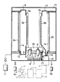
- FIG. 1 is a plan view schematically showing an embodiment of a vacuum processing apparatus provided with a plurality of vacuum chambers.
- FIG. 2 is a side view schematically showing a state in which the vacuum processing chamber 10 is viewed from the transport direction shown by the arrow in FIG.
- a plurality of vacuum chambers having various functions are connected to the vacuum processing apparatus 100 of the present embodiment via a gate valve 14.
- three direction changing chambers 18 are connected in series via the gate valve 14, and each direction changing chamber 18 is provided with a carrier (mounting table) 20 described later.
- a rotation mechanism (turn table) 22 is provided.
- two or three vacuum processing chambers 10 are connected around the respective direction changing chambers 18 via gate valves 14.
- the vacuum processing chamber 10 of the present embodiment is formed of, for example, a sputtering film forming chamber, but is not limited to this, and there may be another processing chamber which performs only heating and cooling.
- an intermediate chamber 19 as a spare chamber is connected to one of the three redirecting chambers 18 via a gate valve 14.
- a two-chamber load lock chamber 21 for stocking the substrate and for taking in and out the substrate between the vacuum space and the atmosphere via the gate valve 14.
- These chambers are partitioned as vacuum spaces, and each include a transport track 7 and a transport mechanism described later.
- the number of direction changing chambers 18 connected in series via the gate valve 14 and the number of vacuum processing chambers 10 connected to each direction changing chamber 18 via the gate valve 14 are limited to the number in this embodiment. I will not.
- a transport track 7 defining the transport direction is laid.
- a plurality of bearings 6 as guide members are supported on the transport track 7 along the track.
- the bearings 6 support the carrier 20, and the bearing 6 is engaged with a concave support 5 formed on the lower surface of the carrier 20. That is, the carrier 20 moves on the transport track 7 while being supported by and guided by the bearing 6.
- the weight of the entire carrier 20 reaches, for example, about 200 kg or more, since the self-supporting structure is symmetrical with respect to the width direction of the transport track 7, it is stably supported by the bearing 6.
- a vibration-proof material 8 is interposed in the lower part of the transport track 7 to suppress the transmission of vibration during transport of the carrier 20 to the vacuum processing chamber 10.
- the carrier transport mechanism will be described later.
- Substrate trays 4a and 4b holding substrates 3a and 3b as transported objects are provided on the carrier 20 in a standing state.
- the substrates 3a and 3b are made of, for example, a glass substrate or the like, and are held by the substrate trays 4a and 4b so as to face in opposite directions and to turn their backs.
- the substrate trays 4a and 4b are inclined to attach two substrates 3a and 3b to the carrier 20.
- the substrate trays 4a and 4b for holding the substrates 3a and 3b are arranged on both sides of the carrier 20 in FIG. 2, but may be only one side.
- the substrates 3a and 3b are held by the carrier 20 by being pressed at four sides by fixing jigs (not shown) attached to the four sides of the substrate trays 4a and 4b, for example.
- the substrate trays 4a and 4b may be disposed so that the processing surfaces of the substrates 3a and 3b face obliquely upward by inclining the substrate trays 4a and 4b inward at a predetermined angle with respect to the vertical direction.
- the inclination angle with respect to the vertical direction is preferably 0.5 degrees or more and 3 degrees or less. This makes it possible to prevent the substrates 3a and 3b from being ejected during transportation, and stable, high-speed transportation (for example, 500 to 600 mm / sec) becomes possible.
- the substrate trays 4a and 4b may be provided with openings (not shown) for heating the substrates 3a and 3b from the back side.
- An exhaust device 11 for exhausting the inside is connected to each vacuum processing chamber 10.
- the vacuum processing chamber 10 is evacuated to about 2 ⁇ 10 Pa to 2 ⁇ 10 ⁇ 5 Pa by the exhaust device 11. Further, gas supply devices 9a and 9b for supplying a processing gas to the inside are connected to the respective vacuum processing chambers 10.
- the targets 1a and 1b are disposed to face the substrates 3a and 3b, respectively, and the targets 1a and 1b are supported upright by the backing plates 2a and 2b.
- magnet units (not shown) for generating a closed loop magnetic field on the surfaces of the targets 1a and 1b are provided. Furthermore, the upper and lower sides of the space between the substrates 3 a and 3 b and the targets 1 a and 1 b are covered with the shield member 12.
- rack gear 16 As shown in FIG. 2, on one side of the lower surface of the carrier 20, a linear gear toothed in the width direction on one surface of a square bar called rack gear 16 is disposed along the transport direction with its gear portion facing downward. ing.
- the rack gear 16 is disposed only on one side of the lower surface of the carrier 20, but may be disposed on both sides of the lower surface of the carrier 20.
- a circular gear called a pinion gear 17 meshes with the rack gear 16.
- rack and pinion (rack & pinion) conveyance mechanisms are gear mechanisms that convert the rotational movement of the pinion gear 17 into the linear movement of the rack gear 16, and correspond to the carrier conveyance mechanism of the present invention.
- the pinion gear 17 is provided in each vacuum chamber, and is rotated by a driving force of a driving source 13 such as a servomotor disposed on the atmosphere side via a pinion driving device 15 formed of a plurality of intermediate gears.
- a driving source 13 such as a servomotor disposed on the atmosphere side
- a pinion driving device 15 formed of a plurality of intermediate gears.
- the servomotor 13 is connected to the pinion gear 17 and the pinion drive device 15, and is provided on the atmosphere side of each vacuum processing chamber 10.
- the servomotors 13 are electrically connected to the servo amplifiers 23 and the motor controller 24, and the motor controller 24 controls the servomotors 13.
- Each servo motor 13 is provided with an encoder (not shown) as means for detecting the phase difference (or phase angle) of the pinion gear 17.
- the vacuum processing apparatus 100 is provided with a control device 25 that controls each vacuum processing chamber 10 and the like.
- the control device 25 is formed of, for example, a personal computer (PC), and includes a CPU 26 that performs arithmetic processing, and a storage unit 27 that stores a drive control program, parameters, and the like.
- PC personal computer
- the rack gear 16 meshing with the pinion gear 17 moves in the transport direction, and the carrier 20 moves from the processing chamber where the pretreatment is performed, for example.
- the vacuum processing chamber 10 of FIG. 1 To the vacuum processing chamber 10 of FIG.
- the carrier 20 having the substrate trays 4a and 4b holding the substrates 3a and 3b is stopped at a predetermined position of the vacuum processing chamber 10, and is deposited by sputtering while stopped in front of the targets 1a and 1b.
- the carrier 20 on which the predetermined film formation has been completed is moved to the vacuum processing chamber 10 of the next process through the gate valve 14.
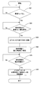
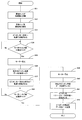
- FIG. 3 is a flowchart showing a drive control method of the rack and pinion mechanism of the first embodiment.
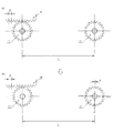
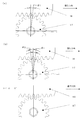
- FIG. 4 is a schematic view showing the meshing relationship between the rack gear and the pinion gear of the first embodiment.
- the algorithm of the drive control method of the rack and pinion mechanism of the first embodiment is stored as a drive control program in the storage unit 27 of the control device 25 and is read and executed by the CPU 26 at the start of operation. Ru.
- the drive control program is a program that causes the control device 25 to execute control of the rack and pinion mechanism based on the detection signal of the encoder of the servo motor 13. That is, the drive control program of the first embodiment has a first step of determining and storing the reference point in the pinion gear 17 of the current process. Further, there is a second step of obtaining an angle of rotation from the reference point from the time when the pinion gear 17 of the current process starts meshing with the rack gear 16 to the time when meshing ends. Furthermore, there is a third step of calculating (360 degrees ⁇ the number of teeth of the pinion gear) as one tooth angle angle of the pinion gear 17 of the current process.
- the fifth step is to rotate the pinion gear 17 of the next process by (one-tooth angle-remainder angle) from the above-mentioned reference point
- the above-mentioned remainder angle is smaller than 1/2 of the above-mentioned one tooth angle
- it has the 6th step which rotates the above-mentioned remainder angle from the above-mentioned standard point in the opposite direction to the advance direction.
- the above-mentioned remainder angle is equal to 1/2 of the above-mentioned one-tooth angle, the control is ended.
- the drive control program is recorded on a recording medium readable by the PC, and installed in the storage unit 27 of the PC.
- Recording media include floppy (registered trademark) disks, magnetic recording media such as ZIP (registered trademark), magneto-optical recording media such as MO, CD-R, DVD-R, DVD + R, CD-R, DVD-RAM, DVD + RW
- optical disks include optical disks such as (registered trademark) and PD.
- Other examples include Compact Flash (registered trademark), SmartMedia (registered trademark), Memory Stick (registered trademark), flash memory systems such as an SD card, and removable disks such as Microdrive (registered trademark) and Jaz (registered trademark).
- the drive control method of this embodiment exemplifies the case where the carrier 20 provided with the substrate trays 4 a and 4 b arrives from the pre-processing chamber to the vacuum processing chamber 10, but the carrier 20 in the actual vacuum processing apparatus 100. Exist, and these are conveyed continuously. This point is the same in the description of the second and third embodiments described later.
- the angle of the pinion gear 17 appears in the following description, since the pinion gear 17 uses the servomotor 13 as a drive source (see FIG. 2), the angle of the pinion gear 17 can be calculated from the value of the encoder of the servomotor 13.
- the substrate tray 4a, 4b is mechanically fixed to fix the position of the rack gear 16 (S2).
- the rack gear 16 With this rack gear 16 fixed, as shown in FIG. 4C, for example, the centers of the valleys of the teeth of the rack gear 16 and the centers of the valleys of the teeth of the pinion gear 17 are made to coincide with each other.
- the pinion gear 17 be a reference point of 0 degrees in the meshing relationship.
- the rack gear 16 moves while meshing with the pinion gear 17 even if the teeth of the pinion gear 17 exist at the 0 degree reference point by default, so the angle of the pinion gear 17 changes depending on the movement distance of the rack gear 16 , Not always at 0 degrees.
- the direction (angle) of the teeth of the pinion gear 17 in the next process to which the rack gear 16 moves is controlled so as to always be the same with respect to the rack gear 16
- the device 25 performs drive control.
- the angle of rotation from the reference point of 0 degrees is determined from the time when the pinion gear 17 of the current process starts meshing with the rack gear 16 until the time when meshing ends.
- the angle (pivotal angle) at which the pinion gear 17 rotates for transporting the carrier 20 is ⁇ . If theta is a multiple of 360 degrees, the pinion gear 17 will naturally be in the same state as before rotation. Then, it is determined whether the pinion gear rotation angle ⁇ is larger than 360 degrees (S3). If the pinion gear rotation angle ⁇ > 360 degrees (S3 / Yes), 360 degrees is subtracted from ⁇ ( ⁇ -360 degrees), and ⁇ is set to a value of 360 degrees or less (S4).
- the value obtained here is ⁇ ′, and ⁇ -360 ° is repeated until ⁇ ′ becomes 360 ° or less ( ⁇ ′ ⁇ 360 °).
- ⁇ ′ becomes 360 ° or less
- 360 degrees are deducted, the case where the pinion gear 17 rotates ⁇ degrees and the case where it rotates ⁇ ′ degrees are in the same state.
- the steps from S3 to S6 can not be divided by dividing the rotation angle ⁇ by one tooth angle and calculating the rotation angle ⁇ of the pinion gear 17, calculating one tooth angle of the pinion gear 17, and dividing the rotation angle ⁇ by one tooth angle.
- the step of calculating the remainder angle ⁇ ′ ( ⁇ ′ ′) may be performed, and the remainder angle ⁇ ′ ( ⁇ ′ ′) is the phase difference from the reference point.
- the pinion 17 is advanced by ⁇ of one tooth angle-remainder angle ⁇ ′ ′
- the teeth are rotated in the direction (S8) because the teeth of the pinion gear 17 collide with the teeth of the rack gear 16 and interfere with each other even if the pinion gear 17 is rotated by ⁇ ′ ′ in the direction opposite to the traveling direction.
- the pinion gear 17 managed by the control device 25 Since the positional relationship between the rack gear 16 and the pinion gear 17 when controlling the pinion gear 17 as in S8 and S10 is the same as the state of the reference point in FIG. 4C, the pinion gear 17 managed by the control device 25. The present angle is changed to a reference point of 0 degrees for recognition (S11). Based on such arithmetic processing, the angular alignment of the pinion gear 17 of the vacuum processing chamber 10 in the next process is performed (S12), and the fixation of the substrate trays 4a and 4b is released (S13). Then, the pinion gear 17 of the current process and the pinion gear 17 of the next process are synchronously controlled to move the carrier 20 including the substrate trays 4a and 4b to the vacuum processing chamber 10 of the next process (S14).
- the control device 25 stores the phase difference of the pinion gear 17 of the current process detected by the encoder, and the pinion gear 17 of the current process.
- the phase difference of the pinion gear 17 in the next process is controlled based on the phase difference of Therefore, the rack gear 16 and the pinion gear 17 have the positional relationship of the reference point of 0 degrees each time, and the carrier 20 can be sent out to the vacuum processing chamber 10 of the next process in the same state. Therefore, the collision between the tooth tips due to the phase shift of the rack gear 16 and the pinion gear 17 can be avoided by a simple mechanism, and the rack gear 16 and the pinion gear 17 can be meshed smoothly.
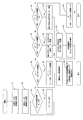
- FIG. 5 is a flowchart showing a drive control method of the rack and pinion mechanism of the second embodiment.
- FIG. 6 is a schematic view showing the meshing relationship between the rack gear and the pinion gear of the second embodiment.
- the configurations of the vacuum processing apparatus and the rack and pinion mechanism are the same as those of the first embodiment, and thus the description thereof is omitted.
- the algorithm of the drive control method of the rack and pinion mechanism of the second embodiment is stored as a drive control program in the storage unit 27 of the control device 25 and is read and executed by the CPU 26 at the start of operation. Ru.
- the drive control program is a program that causes the control device 25 to execute control of the rack and pinion mechanism based on a detection signal of the encoder or the like of the servomotor 13. That is, the drive control program of the second embodiment calculates the phase difference from the distance L between the pinion gear 17 of the current step and the pinion gear 17 of the next step, the tooth pitch p of the rack gear 16 and the number of teeth of the pinion gear 17 of the next step. And store the first step. In addition, there is a second step of rotating the pinion gear 17 in the advancing direction in the next process based on the phase difference. Furthermore, an expansion component calculated from the thermal expansion coefficient corresponding to the ambient temperature of the installation environment of the rack gear 16 is added mainly to the tooth pitch (p) of the rack gear 16 (tooth pitch of the rack gear 16 after thermal expansion (p ' ))).
- the drive control program is recorded on a recording medium readable by the PC, and installed in the storage unit 27 of the PC.
- Examples of the recording medium include the same as those in the first embodiment.
- the presence or absence of the substrate trays 4a and 4b in the vacuum processing chamber 10 of the current process is determined (S21).
- the unloading of the carrier 20 including the substrate trays 4a and 4b is requested from the pretreatment chamber (S22).
- the distance (L) between the pinion gear 17 of the current step and the pinion gear 17 of the next step, the tooth pitch (p) of the rack gear 16, and the number of teeth of the pinion gear 17 of the next step The phase difference ⁇ is calculated from and stored. Then, as shown in FIGS. 6A and 6B, the pinion gear 17 in the next step is rotated in the advancing direction by the phase difference ⁇ (S23).
- L (n (integer) ⁇ p), and the remainder A of L / p ′ is the amount of deviation, and A / p ′ ⁇ (360 ° number of teeth of pinion gear in next step) is It becomes the phase difference ⁇ .
- the pinion gear 17 of the next step is previously rotated in the advancing direction by the phase difference ⁇ .
- control device 25 reports completion of preparation for carrying in to the pretreatment chamber (S24).
- the control device 25 synchronously controls the rotations of the servomotors 13 of both the pinion gear 17 of the current process and the pinion gear 17 of the next process.
- the tray is moved to the vacuum processing chamber 10 of the next step (S26).
- the positional relationship between the rack gear 16 and the pinion gear 17 in the current step and the pinion gear 17 in the next step always synchronizes when the carrier 20 starts moving, and the same also applies when the rack gear 16 meshes with the pinion gear 17 in the next step. It will be in the state. Therefore, by sequentially repeating such a series of operations, it is possible to avoid a collision in the case where the tooth tips of the rack gear 16 and the pinion gear 17 are shifted, and smooth meshing of the rack gear 16 and the pinion gear 17 can be realized. Moreover, since it is not necessary to arrange a complicated mechanism in the vacuum processing chamber 10, adjustment and maintenance can be easily performed.
- the tooth pitch (p ') is further increased by adding the expansion calculated from the thermal expansion coefficient of the material of the rack gear 16 corresponding to the ambient temperature of the installation environment in the vacuum processing chamber 10 or the like. Smooth engagement can be achieved. That is, the thermal expansion due to the ambient temperature mainly affects the tooth pitch (p) of the rack gear 16.
- the temperature measurement of the rack gear 16 is configured, for example, so that the rack gear 16 can be observed from the outside of the vacuum processing chamber 10, and is measured by a radiation thermometer (not shown). Then, the amount of deviation A is calculated from the relationship among the temperature stored in the storage unit 27 of the control unit 25, the coefficient of thermal expansion, the rate of change due to movement, etc., and the pinion gear 17 in the next process is adjusted optimally.
- the collision between the tooth tips due to the phase shift between the rack gear 16 and the pinion gear 17 can be avoided by a simple mechanism and control, and the rack gear 16 and the pinion gear 17 can be meshed smoothly. it can.
- FIG. 7 is a flowchart showing a drive control method of the rack and pinion mechanism of the third embodiment.
- FIG. 8 is a schematic view showing the meshing relationship between the rack gear and the pinion gear of the third embodiment.
- the configurations of the vacuum processing apparatus and the rack and pinion mechanism are the same as those of the first embodiment, and thus the description thereof is omitted.
- the algorithm of the drive control method of the rack and pinion mechanism of the third embodiment is stored as a drive control program in the storage unit 27 of the control device 25 and read and executed by the CPU 26 at the start of operation. Ru.
- the drive control program is a program that causes the control device 25 to execute control of the rack and pinion mechanism based on the detection signal of the encoder of the servo motor 13. That is, the drive control program has a first step of rotating the pinion gear 17 meshing with the rack gear 16 in one direction at a lower speed than the normal set conveyance speed while the carrier 20 is conveyed. Further, there is a second step of storing the first phase angle of the pinion gear 17 rotated in one direction when the torque value of the servomotor 13 becomes equal to or greater than the designated torque. Furthermore, it has a third step of rotating the pinion gear 17 at a low speed in the direction opposite to the one direction.
- the drive control program is recorded on a recording medium readable by the PC, and installed in the storage unit 27 of the PC.
- Examples of the recording medium include the same as those in the first embodiment.
- the carrier 20 provided with the substrate trays 4a and 4b arrives at the vacuum processing chamber 10 (S31), the substrate trays 4a and 4b are mechanically fixed and the rack gear 16 is fixed. The position is fixed (S32). In this position fixing, the carrier 20 and the rack gear are introduced to the pinion gear 17 at a lower speed than the set conveying speed.
- the pinion gear 17 meshing with the rack gear 16 is rotated at a very low speed in one direction (for example, the traveling direction) (S33).
- the low speed referred to in the present invention is a speed sufficiently slower than the normal set conveyance speed, and rotation that does not affect the mechanical strength at all even if the teeth of the pinion gear 17 collide with the teeth of the rack gear 16 A speed, for example, a rotational speed of 1 mm / sec or less.
- the current value of the servomotor 13 currently monitored is taken in into the control apparatus 25, and is managed. That is, it is judged by the current value of the servomotor 13 whether the torque value of the servomotor 13 becomes equal to or more than the designated torque (S34). Then, when the current value of the servomotor 13 becomes equal to or higher than the designated torque (S34 / Yes), the servomotor 13 is stopped (S35), and at that time, the detection signal of the first phase angle ⁇ 1 of the pinion gear 17 by the encoder is The data is input and stored in the storage unit 27 (S36).
- the pinion gear 17 is rotated in the opposite direction to the one direction (for example, the reverse direction to the traveling direction) (S37), and the current of the servomotor 13 is similarly determined whether the torque value of the servomotor 13 becomes equal to or more than the designated torque. It judges by a value (S38). Then, when the current value of the servomotor 13 becomes equal to or greater than the designated torque (S38 / Yes), the servomotor 13 is stopped (S39), and as shown in FIG. 8B, the encoder stops from the initial position The second phase angle ⁇ 2 of the pinion gear 17 up to the point in time is detected and stored in the storage unit 27 (S40).
- the control of the control device 25 does not require a complicated mechanism, and the meshing relationship between the rack gear 16 and the pinion gear 17 meshing with the rack gear 16 during transport of the substrates 3a and 3b. It is possible to adjust itself and continue stable transportation. This can improve the reliability of long-time continuous operation of the rack and pinion mechanism.
Landscapes
- Engineering & Computer Science (AREA)
- Chemical & Material Sciences (AREA)
- General Engineering & Computer Science (AREA)
- Mechanical Engineering (AREA)
- Chemical Kinetics & Catalysis (AREA)
- Materials Engineering (AREA)
- Metallurgy (AREA)
- Organic Chemistry (AREA)
- Transmission Devices (AREA)
- Container, Conveyance, Adherence, Positioning, Of Wafer (AREA)
- Physical Vapour Deposition (AREA)
Abstract
Description
上記ピニオンギヤの位相差分を検出する手段と、
上記検出手段が検出した上記ピニオンギヤの位相差分を記憶する記憶部を有し、上記現工程のピニオンギヤの位相差分に基づいて、上記次工程のピニオンギヤの位相差分を制御する制御装置と、
を備えていることを特徴とするラック・アンド・ピニオン機構である。
駆動源に連結され、上記ラックギヤに順次噛合して上記載置台を移動させる複数のピニオンギヤと、
上記ピニオンギヤの位相角を検出する手段と、
上記検出手段により検出された上記ピニオンギヤの位相角を記憶する記憶部を有する制御装置と、
を備え、
上記制御装置は、上記載置台の搬送中に上記駆動源を制御して、上記ラックギヤに噛合している上記ピニオンギヤを設定搬送速度よりも低速で一方向へ回転させて、上記駆動源のトルク値が指定トルク以上となったときに、上記検出手段が検出した上記一方向へ回転した上記ピニオンギヤの第1の位相角を記憶し、
上記ピニオンギヤを上記低速で上記一方向と逆方向へ回転させて、上記駆動源のトルク値が指定トルク以上となったときに、上記検出手段が検出した上記逆方向へ回転した上記ピニオンギヤの第2の位相角を記憶し、
上記第1の位相角から前記第2の位相角までの回動角の1/2の角度を算出して、該1/2の角度へ上記ピニオンギヤを回転させることを特徴とするラック・アンド・ピニオン機構である。
〈真空処理装置〉
図1は、複数の真空室を備えた真空処理装置の一実施形態を模式的に示す平面図である。図2は、図1中の矢印で示す搬送方向から真空処理室10を観た状態を模式的に示す側面図である。
次に、図2を参照して、上記キャリア搬送機構としてのラック・アンド・ピニオン機構について説明する。
次に、図3及び図4を参照して、上記ラック・アンド・ピニオン機構の作用と共に、第1の実施形態のラック・アンド・ピニオン機構の駆動制御方法について説明する。図3は、第1の実施形態のラック・アンド・ピニオン機構の駆動制御方法を示すフローチャートである。図4は、第1の実施形態のラックギヤとピニオンギヤとの噛合関係を示す模式図である。
次に、図5及び図6を参照して、第2の実施形態のラック・アンド・ピニオン機構の駆動制御方法について説明する。図5は、第2の実施形態のラック・アンド・ピニオン機構の駆動制御方法を示すフローチャートである。図6は、第2の実施形態のラックギヤとピニオンギヤとの噛合関係を示す模式図である。なお、真空処理装置及びラック・アンド・ピニオン機構の構成については、第1の実施形態と共通であるので、説明を省略する。
次に、図7及び図8を参照して、第3の実施形態のラック・アンド・ピニオン機構の駆動制御方法について説明する。図7は、第3の実施形態のラック・アンド・ピニオン機構の駆動制御方法を示すフローチャートである。図8は、第3の実施形態のラックギヤとピニオンギヤとの噛合関係を示す模式図である。なお、真空処理装置及びラック・アンド・ピニオン機構の構成については、第1の実施形態と共通であるので、説明を省略する。
3a、3b 基板
4a、4b 基板トレイ
7 搬送軌道
10 真空処理室
13 駆動源(サーボモータ)
15 ピニオン駆動装置
16 ラックギヤ
17 ピニオンギヤ
20 キャリア(載置台)
23 サーボアンプ
24 モーターコントローラ
25 制御装置
26 CPU
27 記憶部
Claims (22)
- 被搬送物を搭載して搬送軌道上を移動する載置台に固定されたラックギヤと、駆動源に連結され、前記ラックギヤに噛合する複数のピニオンギヤと、を備え、これらピニオンギヤのうち、少なくとも2つが同期して回転して前記ラックギヤに順次噛合することにより、前記ラックギヤを現工程のピニオンギヤから次工程のピニオンギヤへと受け渡して、前記載置台を搬送するラック・アンド・ピニオン機構であって、
前記ピニオンギヤの位相差分を検出する手段と、
前記検出手段が検出した前記ピニオンギヤの位相差分を記憶する記憶部を有し、前記現工程のピニオンギヤの位相差分に基づいて、前記次工程のピニオンギヤの位相差分を制御する制御装置と、
を備えていることを特徴とするラック・アンド・ピニオン機構。 - 前記制御装置は、
前記現工程のピニオンギヤに基準点を決定して記憶し、
前記現工程のピニオンギヤが前記ラックギヤと噛合開始した時から噛合終了時までに、前記基準点から回転した角度を求め、
前記現工程のピニオンギヤの1歯数角として、(360度÷ピニオンギヤの歯数)を算出し、
前記回転角を前記1歯数角で割って余り角を算出し、
前記余り角が前記1歯数角の1/2より大きい場合は、前記次工程のピニオンギヤを前記基準点から(1歯数角-余り角)分を進行方向に回動させ、
一方、前記余り角が前記1歯数角の1/2より小さい場合は、前記次工程のピニオンギヤを前記基準点から前記余り角分を進行方向と逆方向に回転させることを特徴とする請求項1に記載のラック・アンド・ピニオン機構。 - 前記余り角が前記1歯数角の1/2と同一の場合は、制御を終了することを特徴とする請求項2に記載のラック・アンド・ピニオン機構。
- 前記制御装置は、
前記現工程のピニオンギヤと前記次工程のピニオンギヤとの距離L、前記ラックギヤの歯ピッチp及び前記次工程のピニオンギヤの歯数から、位相差分を算出して前記記憶部に記憶し、
前記位相差分に基づいて、前記次工程のピニオンギヤを進行方向へ回転させることを特徴とする請求項1に記載のラック・アンド・ピニオン機構。 - 前記ラックギヤの歯ピッチpには、設置環境の雰囲気温度に対応する熱膨張係数より算出した膨張分が加算されることを特徴とする請求項4に記載のラック・アンド・ピニオン機構。
- 前記被搬送物が基板であって、前記載置台の搬送機構として請求項1から5のいずれか1項に記載のラック・アンド・ピニオン機構を備え、
搬送軌道に沿って複数の真空室が接続され、各真空室にそれぞれ前記ピニオンギヤが設けられていることを特徴とする真空処理装置。 - 被搬送物を搭載して搬送軌道上を移動する載置台に固定されたラックギヤと、駆動源に連結され、前記ラックギヤに噛合する複数のピニオンギヤと、を備え、これらピニオンギヤのうち、少なくとも2つが同期して回転して前記ラックギヤに順次噛合することにより、前記ラックギヤを現工程のピニオンギヤから次工程のピニオンギヤへと受け渡して、前記載置台を搬送するラック・アンド・ピニオン機構の駆動制御方法において、
前記現工程のピニオンギヤに基準点を決定して記憶するステップと、
前記現工程のピニオンギヤが前記ラックギヤと噛合開始した時から噛合終了時までに、前記基準点から回転した角度を求めるステップと、
前記現工程のピニオンギヤの1歯数角として、(360度÷ピニオンギヤの歯数)を算出するステップと、
前記回転角を前記1歯数角で割って余り角を算出するステップと、
前記余り角が前記1歯数角の1/2より大きい場合は、前記次工程のピニオンギヤを前記基準点から(1歯数角-余り角)分を進行方向に回動させるステップと、
一方、前記余り角が前記1歯数角の1/2より小さい場合は、前記次工程のピニオンギヤを前記基準点から前記余り角分を進行方向と逆方向に回転させるステップと、
を有することを特徴とするラック・アンド・ピニオン機構の駆動制御方法。 - 前記余り角が前記1歯数角の1/2と同一の場合は、制御を終了することを特徴とする請求項7に記載のラック・アンド・ピニオン機構の駆動制御方法。
- 被搬送物を搭載して搬送軌道上を移動する載置台に固定されたラックギヤと、駆動源に連結され、前記ラックギヤに噛合する複数のピニオンギヤと、を備え、これらピニオンギヤのうち、少なくとも2つが同期して回転して前記ラックギヤに順次噛合することにより、前記ラックギヤを現工程のピニオンギヤから次工程のピニオンギヤへと受け渡して、前記載置台を搬送するラック・アンド・ピニオン機構の駆動制御方法において、
前記現工程のピニオンギヤと前記次工程のピニオンギヤとの距離L、前記ラックギヤの歯ピッチp及び前記次工程のピニオンギヤの歯数から、位相差分を算出して記憶するステップと、
前記位相差分に基づいて、前記次工程のピニオンギヤを進行方向へ回転させるステップと、
を有することを特徴とするラック・アンド・ピニオン機構の駆動制御方法。 - 前記ラックギヤの歯ピッチpには、設置環境の雰囲気温度に対応する熱膨張係数より算出した膨張分を加算することを特徴とする請求項9に記載のラック・アンド・ピニオン機構の駆動制御方法。
- 被搬送物を搭載して搬送軌道上を移動する載置台に固定されたラックギヤと、駆動源に連結され、前記ラックギヤに噛合する複数のピニオンギヤと、を備え、これらピニオンギヤのうち、少なくとも2つが同期して回転して前記ラックギヤに順次噛合することにより、前記ラックギヤを現工程のピニオンギヤから次工程のピニオンギヤへと受け渡して、前記載置台を搬送するラック・アンド・ピニオン機構の駆動制御プログラムにおいて、
前記現工程のピニオンギヤに基準点を決定して記憶するステップと、
前記現工程のピニオンギヤが前記ラックギヤと噛合開始した時から噛合終了時までに、前記基準点から回転した角度を求めるステップと、
前記現工程のピニオンギヤの1歯数角として、(360度÷ピニオンギヤの歯数)を算出するステップと、
前記回転角を前記1歯数角で割って余り角を算出するステップと、
前記余り角が前記1歯数角の1/2より大きい場合は、前記次工程のピニオンギヤを前記基準点から(1歯数角-余り角)分を進行方向に回動させるステップと、
一方、前記余り角が前記1歯数角の1/2より小さい場合は、前記次工程のピニオンギヤを前記基準点から前記余り角分を進行方向と逆方向に回転させるステップと、
を前記ラック・アンド・ピニオン機構を制御する制御装置に実行させることを特徴とする駆動制御プログラム。 - 前記余り角が前記1歯数角の1/2と同一の場合は、制御を終了することを特徴とする請求項11に記載の駆動制御プログラム。
- 被搬送物を搭載して搬送軌道上を移動する載置台に固定されたラックギヤと、駆動源に連結され、前記ラックギヤに噛合する複数のピニオンギヤと、を備え、これらピニオンギヤのうち、少なくとも2つが同期して回転して前記ラックギヤに順次噛合することにより、前記ラックギヤを現工程のピニオンギヤから次工程のピニオンギヤへと受け渡して、前記載置台を搬送するラック・アンド・ピニオン機構の駆動制御プログラムにおいて、
前記現工程のピニオンギヤと前記次工程のピニオンギヤとの距離L、前記ラックギヤの歯ピッチp及び前記次工程のピニオンギヤの歯数から、位相差分を算出して記憶するステップと、
前記位相差分に基づいて、前記次工程のピニオンギヤを進行方向へ回転させるステップと、
を前記ラック・アンド・ピニオン機構を制御する制御装置に実行させることを特徴とする駆動制御プログラム。 - 前記ラックギヤの歯ピッチpには、設置環境の雰囲気温度に対応する熱膨張係数より算出した膨張分を加算することを特徴とする請求項13に記載の駆動制御プログラム。
- 請求項11から14のいずれか1項に記載の駆動制御プログラムを記録したコンピュータで読み取り可能な記録媒体。
- 被搬送物を搭載して搬送軌道上を移動する載置台に固定されたラックギヤと、
駆動源に連結され、前記ラックギヤに順次噛合して前記載置台を移動させる複数のピニオンギヤと、
前記ピニオンギヤの位相角を検出する手段と、
前記検出手段により検出された前記ピニオンギヤの位相角を記憶する記憶部を有する制御装置と、
を備え、
前記制御装置は、
前記載置台の搬送中に前記駆動源を制御して、前記ラックギヤに噛合している前記ピニオンギヤを設定搬送速度よりも低速で一方向へ回転させて、前記駆動源のトルク値が指定トルク以上となったときに、前記検出手段が検出した前記一方向へ回転した前記ピニオンギヤの第1の位相角を記憶し、
前記ピニオンギヤを前記低速で前記一方向と逆方向へ回転させて、前記駆動源のトルク値が指定トルク以上となったときに、前記検出手段が検出した前記逆方向へ回転した前記ピニオンギヤの第2の位相角を記憶し、
前記第1の位相角から前記第2の位相角までの回動角の1/2の角度を算出して、該1/2の角度へ前記ピニオンギヤを回転させることを特徴とするラック・アンド・ピニオン機構。 - 前記ラックギヤは前記設定搬送速度よりも低速で前記ピニオンギヤへと導入され、前記ラックギヤを固定して前記制御装置による制御を行うことを特徴とする請求項16に記載のラック・アンド・ピニオン機構。
- 前記被搬送物が基板であって、前記載置台の搬送機構として請求項16に記載のラック・アンド・ピニオン機構を備え、
前記搬送軌道に沿って複数の真空室が接続され、各真空室にそれぞれ前記ピニオンギヤが設けられていることを特徴とする真空処理装置。 - 被搬送物を搭載して搬送軌道上を移動する載置台に固定されたラックギヤと、駆動源に連結され、前記ラックギヤに順次噛合して前記載置台を移動させる複数のピニオンギヤと、からなるラック・アンド・ピニオン機構の駆動制御方法であって、
前記載置台の搬送中に、前記ラックギヤに噛合している前記ピニオンギヤを設定搬送速度よりも低速で一方向へ回転させるステップと、
前記駆動源のトルク値が指定トルク以上となったときに、前記一方向へ回転した前記ピニオンギヤの第1の位相角を記憶するステップと、
前記ピニオンギヤを前記低速で前記一方向と逆方向へ回転させるステップと、
前記駆動源のトルク値が指定トルク以上となったときに、前記逆方向へ回転した前記ピニオンギヤの第2の位相角を記憶するステップと、
前記第1の位相角から前記第2の位相角までの回動角の1/2の角度を算出して、該1/2の角度へ前記ピニオンギヤを回転させるステップと、
を有することを特徴とするラック・アンド・ピニオン機構の駆動制御方法。 - 前記ラックギヤは前記設定搬送速度よりも低速で前記ピニオンギヤへと導入され、前記ラックギヤを固定して制御を行うことを特徴とする請求項19に記載のラック・アンド・ピニオン機構の駆動制御方法。
- 被搬送物を搭載して搬送軌道上を移動する載置台に固定されたラックギヤと、駆動源に連結され、前記ラックギヤに順次噛合して前記載置台を移動させる複数のピニオンギヤと、からなるラック・アンド・ピニオン機構の駆動制御プログラムであって、
前記載置台の搬送中に、前記ラックギヤに噛合している前記ピニオンギヤを設定搬送速度よりも低速で一方向へ回転させるステップと、
前記駆動源のトルク値が指定トルク以上となったときに、前記一方向へ回転した前記ピニオンギヤの第1の位相角を記憶するステップと、
前記ピニオンギヤを前記低速で前記一方向と逆方向へ回転させるステップと、
前記駆動源のトルク値が指定トルク以上となったときに、前記逆方向へ回転した前記ピニオンギヤの第2の位相角を記憶するステップと、
前記第1の位相角から前記第2の位相角までの回動角の1/2の角度を算出して、該1/2の角度へ前記ピニオンギヤを回転させるステップと、
をラック・アンド・ピニオン機構を制御する制御装置に実行させることを特徴とする駆動制御プログラム。 - 請求項21に記載の駆動制御プログラムを記録したコンピュータで読み取り可能な記録媒体。
Priority Applications (3)
| Application Number | Priority Date | Filing Date | Title |
|---|---|---|---|
| CN200980149561.5A CN102245934A (zh) | 2008-12-09 | 2009-12-09 | 齿条-小齿轮机构、真空处理装置、齿条-小齿轮机构的驱动控制方法、驱动控制程序及记录介质 |
| JP2010542018A JP5249351B2 (ja) | 2008-12-09 | 2009-12-09 | ラック・アンド・ピニオン機構、真空処理装置、ラック・アンド・ピニオン機構の駆動制御方法、駆動制御プログラム及び記録媒体 |
| US13/133,228 US20110253953A1 (en) | 2008-12-09 | 2009-12-09 | Rack and pinion mechanism, vacuum processing apparatus, method of driving and controlling rack and pinion mechanism, drive control program, and recording medium |
Applications Claiming Priority (4)
| Application Number | Priority Date | Filing Date | Title |
|---|---|---|---|
| JP2008313139 | 2008-12-09 | ||
| JP2008-313139 | 2008-12-09 | ||
| JP2008313147 | 2008-12-09 | ||
| JP2008-313147 | 2008-12-09 |
Publications (1)
| Publication Number | Publication Date |
|---|---|
| WO2010067591A1 true WO2010067591A1 (ja) | 2010-06-17 |
Family
ID=42242584
Family Applications (1)
| Application Number | Title | Priority Date | Filing Date |
|---|---|---|---|
| PCT/JP2009/006716 Ceased WO2010067591A1 (ja) | 2008-12-09 | 2009-12-09 | ラック・アンド・ピニオン機構、真空処理装置、ラック・アンド・ピニオン機構の駆動制御方法、駆動制御プログラム及び記録媒体 |
Country Status (4)
| Country | Link |
|---|---|
| US (1) | US20110253953A1 (ja) |
| JP (2) | JP5249351B2 (ja) |
| CN (2) | CN103540905B (ja) |
| WO (1) | WO2010067591A1 (ja) |
Cited By (6)
| Publication number | Priority date | Publication date | Assignee | Title |
|---|---|---|---|---|
| JP2012158805A (ja) * | 2011-01-31 | 2012-08-23 | Ihi Corp | アレイアンテナ式プラズマcvd装置 |
| CN103074591A (zh) * | 2011-10-25 | 2013-05-01 | 佳能安内华股份有限公司 | 输送装置及具有该输送装置的处理装置 |
| CN114598099A (zh) * | 2020-12-04 | 2022-06-07 | 日本电产科宝株式会社 | 驱动装置 |
| WO2023149071A1 (ja) * | 2022-02-03 | 2023-08-10 | 川崎重工業株式会社 | ロボットおよびロボットの制御方法 |
| WO2024004954A1 (ja) * | 2022-06-28 | 2024-01-04 | 株式会社ブイ・テクノロジー | 搬送装置 |
| USD1121856S1 (en) | 2024-02-26 | 2026-04-07 | Nacacue Corporation | Lighting device |
Families Citing this family (12)
| Publication number | Priority date | Publication date | Assignee | Title |
|---|---|---|---|---|
| US9145956B2 (en) | 2013-01-25 | 2015-09-29 | Gustomsc Resources B.V. | Torque sharing drive and torque sharing process |
| US9274026B1 (en) * | 2013-02-26 | 2016-03-01 | L-3 Communications Corp. | Determining an angular position of an output gear |
| US9531237B2 (en) | 2013-12-19 | 2016-12-27 | Gustomsc Resources B.V. | Dual rack output pinion drive |
| WO2016056275A1 (ja) * | 2014-10-10 | 2016-04-14 | キヤノンアネルバ株式会社 | 成膜装置 |
| KR101834613B1 (ko) | 2015-03-24 | 2018-03-06 | 주식회사 유니플라즈마 | 캐리어 이송 시스템 및 방법 |
| DE102017106373A1 (de) * | 2017-03-24 | 2018-09-27 | Nexwafe Gmbh | Prozesskammerführung, Prozesskammer und Verfahren zum Führen eines Substratträgers in eine Prozessposition |
| JP7202902B2 (ja) * | 2019-01-21 | 2023-01-12 | 東京エレクトロン株式会社 | 搬送装置 |
| DE102019201714A1 (de) * | 2019-02-11 | 2019-05-09 | Festo Ag & Co. Kg | Positioniersystem zur Positionierung eines Positionierschlittens und Verfahren zum Betreiben eines Schlittenträgers in einem Positioniersystem |
| JP7306959B2 (ja) * | 2019-10-29 | 2023-07-11 | 株式会社アルバック | 搬送装置、および、真空処理装置 |
| CN114229362B (zh) * | 2021-09-27 | 2024-02-09 | 茂硕电源科技股份有限公司 | 高精度传输装置 |
| TWI843196B (zh) * | 2022-09-08 | 2024-05-21 | 凌嘉科技股份有限公司 | 旋轉移載式立式鍍膜設備及雙面多層膜的鍍膜方法 |
| CN116621400B (zh) * | 2023-07-25 | 2023-10-10 | 中国市政工程西南设计研究总院有限公司 | 一种高品质水净化处理系统 |
Citations (8)
| Publication number | Priority date | Publication date | Assignee | Title |
|---|---|---|---|---|
| JPS6353055U (ja) * | 1986-09-24 | 1988-04-09 | ||
| JPS63108997A (ja) * | 1986-10-23 | 1988-05-13 | Ishikawajima Harima Heavy Ind Co Ltd | 全姿勢溶接装置の駆動方法 |
| JPH04125222A (ja) * | 1990-09-17 | 1992-04-24 | Kokusai Electric Co Ltd | 真空装置用縦型トレイ搬送機構 |
| JPH0678655U (ja) * | 1993-04-15 | 1994-11-04 | 日電アネルバ株式会社 | ラック・ピニオン噛合い機構 |
| JPH09291360A (ja) * | 1996-04-24 | 1997-11-11 | Mitsubishi Heavy Ind Ltd | 基板搬送装置 |
| JP2003221116A (ja) * | 2002-01-30 | 2003-08-05 | Mitsubishi Heavy Ind Ltd | 搬送台車の真空室内走行制御方法 |
| JP2005206051A (ja) * | 2004-01-23 | 2005-08-04 | Toray Eng Co Ltd | 搬送装置 |
| JP2007092871A (ja) * | 2005-09-28 | 2007-04-12 | Isel Co Ltd | リニアガイド装置 |
Family Cites Families (3)
| Publication number | Priority date | Publication date | Assignee | Title |
|---|---|---|---|---|
| JPS63155882U (ja) * | 1987-03-31 | 1988-10-13 | ||
| JPH09144828A (ja) * | 1995-11-22 | 1997-06-03 | Teijin Seiki Co Ltd | バックラッシュ調節付直線運動装置 |
| JPH10158835A (ja) * | 1996-11-29 | 1998-06-16 | Mitsubishi Heavy Ind Ltd | 搬送装置 |
-
2009
- 2009-12-09 JP JP2010542018A patent/JP5249351B2/ja active Active
- 2009-12-09 US US13/133,228 patent/US20110253953A1/en not_active Abandoned
- 2009-12-09 WO PCT/JP2009/006716 patent/WO2010067591A1/ja not_active Ceased
- 2009-12-09 CN CN201310456318.6A patent/CN103540905B/zh active Active
- 2009-12-09 CN CN200980149561.5A patent/CN102245934A/zh active Pending
-
2013
- 2013-04-11 JP JP2013082814A patent/JP5744954B2/ja active Active
Patent Citations (8)
| Publication number | Priority date | Publication date | Assignee | Title |
|---|---|---|---|---|
| JPS6353055U (ja) * | 1986-09-24 | 1988-04-09 | ||
| JPS63108997A (ja) * | 1986-10-23 | 1988-05-13 | Ishikawajima Harima Heavy Ind Co Ltd | 全姿勢溶接装置の駆動方法 |
| JPH04125222A (ja) * | 1990-09-17 | 1992-04-24 | Kokusai Electric Co Ltd | 真空装置用縦型トレイ搬送機構 |
| JPH0678655U (ja) * | 1993-04-15 | 1994-11-04 | 日電アネルバ株式会社 | ラック・ピニオン噛合い機構 |
| JPH09291360A (ja) * | 1996-04-24 | 1997-11-11 | Mitsubishi Heavy Ind Ltd | 基板搬送装置 |
| JP2003221116A (ja) * | 2002-01-30 | 2003-08-05 | Mitsubishi Heavy Ind Ltd | 搬送台車の真空室内走行制御方法 |
| JP2005206051A (ja) * | 2004-01-23 | 2005-08-04 | Toray Eng Co Ltd | 搬送装置 |
| JP2007092871A (ja) * | 2005-09-28 | 2007-04-12 | Isel Co Ltd | リニアガイド装置 |
Cited By (9)
| Publication number | Priority date | Publication date | Assignee | Title |
|---|---|---|---|---|
| JP2012158805A (ja) * | 2011-01-31 | 2012-08-23 | Ihi Corp | アレイアンテナ式プラズマcvd装置 |
| CN103074591A (zh) * | 2011-10-25 | 2013-05-01 | 佳能安内华股份有限公司 | 输送装置及具有该输送装置的处理装置 |
| CN114598099A (zh) * | 2020-12-04 | 2022-06-07 | 日本电产科宝株式会社 | 驱动装置 |
| JP2022089441A (ja) * | 2020-12-04 | 2022-06-16 | 日本電産コパル株式会社 | 駆動装置 |
| WO2023149071A1 (ja) * | 2022-02-03 | 2023-08-10 | 川崎重工業株式会社 | ロボットおよびロボットの制御方法 |
| JP2023113503A (ja) * | 2022-02-03 | 2023-08-16 | 川崎重工業株式会社 | ロボットおよびロボットの制御方法 |
| US12589486B2 (en) | 2022-02-03 | 2026-03-31 | Kawasaki Jukogyo Kabushiki Kaisha | Robot and robot-controlling method |
| WO2024004954A1 (ja) * | 2022-06-28 | 2024-01-04 | 株式会社ブイ・テクノロジー | 搬送装置 |
| USD1121856S1 (en) | 2024-02-26 | 2026-04-07 | Nacacue Corporation | Lighting device |
Also Published As
| Publication number | Publication date |
|---|---|
| CN103540905A (zh) | 2014-01-29 |
| CN103540905B (zh) | 2016-03-16 |
| JP5744954B2 (ja) | 2015-07-08 |
| JP5249351B2 (ja) | 2013-07-31 |
| CN102245934A (zh) | 2011-11-16 |
| JPWO2010067591A1 (ja) | 2012-05-17 |
| JP2013177975A (ja) | 2013-09-09 |
| US20110253953A1 (en) | 2011-10-20 |
Similar Documents
| Publication | Publication Date | Title |
|---|---|---|
| WO2010067591A1 (ja) | ラック・アンド・ピニオン機構、真空処理装置、ラック・アンド・ピニオン機構の駆動制御方法、駆動制御プログラム及び記録媒体 | |
| US8534975B2 (en) | Substrate transport apparatus and method for manufacturing magnetic recording medium | |
| JP5937600B2 (ja) | ベルト調節方法及びベルト搬送システム | |
| JP2018161729A (ja) | 産業用ロボット | |
| CN101826481B (zh) | 基板支承装置、基板处理装置及基板支承方法 | |
| US9022717B2 (en) | Panel-storing shelf and panel-transporting system | |
| US20180237034A1 (en) | Conveyance system | |
| US20100242842A1 (en) | Evaporation system | |
| WO2018088094A1 (ja) | 接合装置、接合システム、接合方法及びコンピュータ記憶媒体 | |
| JP2010189094A (ja) | 搬送物品の一時保管装置 | |
| JP2013018617A (ja) | 搬送車 | |
| JP2011051770A (ja) | カセット搬送装置 | |
| JP2011137497A (ja) | ラック・アンド・ピニオン機構、及びこれを備えた真空処理装置 | |
| TWI798755B (zh) | 基於雙動力驅動的平行移動架及其卸貨裝置 | |
| JP2013092193A (ja) | 搬送装置、及びこの搬送装置を備えた真空処理装置 | |
| JP5530346B2 (ja) | 搬送機構、及び、それを備えた真空処理装置 | |
| JP2010001139A (ja) | 搬送装置及び自動倉庫 | |
| JP5332191B2 (ja) | 移載装置 | |
| TW473418B (en) | Work carrier device and attitude holding method of work carrier device controller for work carrying apparatus | |
| JP2012134344A (ja) | 搬送機構、及び、それを備えた真空処理装置 | |
| CN102084422A (zh) | 用于磁带库的传输设备 | |
| JP6848620B2 (ja) | 搬送装置、加工装置、及び搬送方法 | |
| JP4386455B2 (ja) | 光ピックアップの移送装置 | |
| JP5150575B2 (ja) | 基板ホルダー保持装置及び基板ホルダー収納チャンバ | |
| JPWO2010143371A1 (ja) | 真空処理装置及び光学部品の製造方法 |
Legal Events
| Date | Code | Title | Description |
|---|---|---|---|
| WWE | Wipo information: entry into national phase |
Ref document number: 200980149561.5 Country of ref document: CN |
|
| 121 | Ep: the epo has been informed by wipo that ep was designated in this application |
Ref document number: 09831698 Country of ref document: EP Kind code of ref document: A1 |
|
| ENP | Entry into the national phase |
Ref document number: 2010542018 Country of ref document: JP Kind code of ref document: A |
|
| NENP | Non-entry into the national phase |
Ref country code: DE |
|
| WWE | Wipo information: entry into national phase |
Ref document number: 13133228 Country of ref document: US |
|
| 122 | Ep: pct application non-entry in european phase |
Ref document number: 09831698 Country of ref document: EP Kind code of ref document: A1 |