WO2010067586A1 - 車輪用軸受装置 - Google Patents
車輪用軸受装置 Download PDFInfo
- Publication number
- WO2010067586A1 WO2010067586A1 PCT/JP2009/006700 JP2009006700W WO2010067586A1 WO 2010067586 A1 WO2010067586 A1 WO 2010067586A1 JP 2009006700 W JP2009006700 W JP 2009006700W WO 2010067586 A1 WO2010067586 A1 WO 2010067586A1
- Authority
- WO
- WIPO (PCT)
- Prior art keywords
- ball
- bearing device
- balls
- diameter
- curvature
- Prior art date
- Legal status (The legal status is an assumption and is not a legal conclusion. Google has not performed a legal analysis and makes no representation as to the accuracy of the status listed.)
- Ceased
Links
Images





Classifications
-
- B—PERFORMING OPERATIONS; TRANSPORTING
- B60—VEHICLES IN GENERAL
- B60B—VEHICLE WHEELS; CASTORS; AXLES FOR WHEELS OR CASTORS; INCREASING WHEEL ADHESION
- B60B27/00—Hubs
- B60B27/0005—Hubs with ball bearings
-
- B—PERFORMING OPERATIONS; TRANSPORTING
- B60—VEHICLES IN GENERAL
- B60B—VEHICLE WHEELS; CASTORS; AXLES FOR WHEELS OR CASTORS; INCREASING WHEEL ADHESION
- B60B27/00—Hubs
- B60B27/0078—Hubs characterised by the fixation of bearings
- B60B27/0084—Hubs characterised by the fixation of bearings caulking to fix inner race
-
- B—PERFORMING OPERATIONS; TRANSPORTING
- B60—VEHICLES IN GENERAL
- B60B—VEHICLE WHEELS; CASTORS; AXLES FOR WHEELS OR CASTORS; INCREASING WHEEL ADHESION
- B60B27/00—Hubs
- B60B27/0094—Hubs one or more of the bearing races are formed by the hub
-
- F—MECHANICAL ENGINEERING; LIGHTING; HEATING; WEAPONS; BLASTING
- F16—ENGINEERING ELEMENTS AND UNITS; GENERAL MEASURES FOR PRODUCING AND MAINTAINING EFFECTIVE FUNCTIONING OF MACHINES OR INSTALLATIONS; THERMAL INSULATION IN GENERAL
- F16C—SHAFTS; FLEXIBLE SHAFTS; ELEMENTS OR CRANKSHAFT MECHANISMS; ROTARY BODIES OTHER THAN GEARING ELEMENTS; BEARINGS
- F16C19/00—Bearings with rolling contact, for exclusively rotary movement
- F16C19/02—Bearings with rolling contact, for exclusively rotary movement with bearing balls essentially of the same size in one or more circular rows
- F16C19/14—Bearings with rolling contact, for exclusively rotary movement with bearing balls essentially of the same size in one or more circular rows for both radial and axial load
- F16C19/18—Bearings with rolling contact, for exclusively rotary movement with bearing balls essentially of the same size in one or more circular rows for both radial and axial load with two or more rows of balls
- F16C19/181—Bearings with rolling contact, for exclusively rotary movement with bearing balls essentially of the same size in one or more circular rows for both radial and axial load with two or more rows of balls with angular contact
- F16C19/183—Bearings with rolling contact, for exclusively rotary movement with bearing balls essentially of the same size in one or more circular rows for both radial and axial load with two or more rows of balls with angular contact with two rows at opposite angles
- F16C19/184—Bearings with rolling contact, for exclusively rotary movement with bearing balls essentially of the same size in one or more circular rows for both radial and axial load with two or more rows of balls with angular contact with two rows at opposite angles in O-arrangement
- F16C19/186—Bearings with rolling contact, for exclusively rotary movement with bearing balls essentially of the same size in one or more circular rows for both radial and axial load with two or more rows of balls with angular contact with two rows at opposite angles in O-arrangement with three raceways provided integrally on parts other than race rings, e.g. third generation hubs
-
- F—MECHANICAL ENGINEERING; LIGHTING; HEATING; WEAPONS; BLASTING
- F16—ENGINEERING ELEMENTS AND UNITS; GENERAL MEASURES FOR PRODUCING AND MAINTAINING EFFECTIVE FUNCTIONING OF MACHINES OR INSTALLATIONS; THERMAL INSULATION IN GENERAL
- F16C—SHAFTS; FLEXIBLE SHAFTS; ELEMENTS OR CRANKSHAFT MECHANISMS; ROTARY BODIES OTHER THAN GEARING ELEMENTS; BEARINGS
- F16C33/00—Parts of bearings; Special methods for making bearings or parts thereof
- F16C33/30—Parts of ball or roller bearings
- F16C33/303—Parts of ball or roller bearings of hybrid bearings, e.g. rolling bearings with steel races and ceramic rolling elements
-
- F—MECHANICAL ENGINEERING; LIGHTING; HEATING; WEAPONS; BLASTING
- F16—ENGINEERING ELEMENTS AND UNITS; GENERAL MEASURES FOR PRODUCING AND MAINTAINING EFFECTIVE FUNCTIONING OF MACHINES OR INSTALLATIONS; THERMAL INSULATION IN GENERAL
- F16C—SHAFTS; FLEXIBLE SHAFTS; ELEMENTS OR CRANKSHAFT MECHANISMS; ROTARY BODIES OTHER THAN GEARING ELEMENTS; BEARINGS
- F16C33/00—Parts of bearings; Special methods for making bearings or parts thereof
- F16C33/30—Parts of ball or roller bearings
- F16C33/32—Balls
-
- F—MECHANICAL ENGINEERING; LIGHTING; HEATING; WEAPONS; BLASTING
- F16—ENGINEERING ELEMENTS AND UNITS; GENERAL MEASURES FOR PRODUCING AND MAINTAINING EFFECTIVE FUNCTIONING OF MACHINES OR INSTALLATIONS; THERMAL INSULATION IN GENERAL
- F16C—SHAFTS; FLEXIBLE SHAFTS; ELEMENTS OR CRANKSHAFT MECHANISMS; ROTARY BODIES OTHER THAN GEARING ELEMENTS; BEARINGS
- F16C33/00—Parts of bearings; Special methods for making bearings or parts thereof
- F16C33/30—Parts of ball or roller bearings
- F16C33/38—Ball cages
- F16C33/41—Ball cages comb-shaped
- F16C33/412—Massive or moulded comb cages, e.g. snap ball cages
- F16C33/414—Massive or moulded comb cages, e.g. snap ball cages formed as one-piece cages, i.e. monoblock comb cages
- F16C33/416—Massive or moulded comb cages, e.g. snap ball cages formed as one-piece cages, i.e. monoblock comb cages made from plastic, e.g. injection moulded comb cages
-
- F—MECHANICAL ENGINEERING; LIGHTING; HEATING; WEAPONS; BLASTING
- F16—ENGINEERING ELEMENTS AND UNITS; GENERAL MEASURES FOR PRODUCING AND MAINTAINING EFFECTIVE FUNCTIONING OF MACHINES OR INSTALLATIONS; THERMAL INSULATION IN GENERAL
- F16C—SHAFTS; FLEXIBLE SHAFTS; ELEMENTS OR CRANKSHAFT MECHANISMS; ROTARY BODIES OTHER THAN GEARING ELEMENTS; BEARINGS
- F16C33/00—Parts of bearings; Special methods for making bearings or parts thereof
- F16C33/30—Parts of ball or roller bearings
- F16C33/58—Raceways; Race rings
- F16C33/583—Details of specific parts of races
- F16C33/585—Details of specific parts of races of raceways, e.g. ribs to guide the rollers
-
- F—MECHANICAL ENGINEERING; LIGHTING; HEATING; WEAPONS; BLASTING
- F16—ENGINEERING ELEMENTS AND UNITS; GENERAL MEASURES FOR PRODUCING AND MAINTAINING EFFECTIVE FUNCTIONING OF MACHINES OR INSTALLATIONS; THERMAL INSULATION IN GENERAL
- F16C—SHAFTS; FLEXIBLE SHAFTS; ELEMENTS OR CRANKSHAFT MECHANISMS; ROTARY BODIES OTHER THAN GEARING ELEMENTS; BEARINGS
- F16C33/00—Parts of bearings; Special methods for making bearings or parts thereof
- F16C33/30—Parts of ball or roller bearings
- F16C33/58—Raceways; Race rings
- F16C33/64—Special methods of manufacture
-
- B—PERFORMING OPERATIONS; TRANSPORTING
- B60—VEHICLES IN GENERAL
- B60B—VEHICLE WHEELS; CASTORS; AXLES FOR WHEELS OR CASTORS; INCREASING WHEEL ADHESION
- B60B2380/00—Bearings
- B60B2380/10—Type
- B60B2380/12—Ball bearings
-
- B—PERFORMING OPERATIONS; TRANSPORTING
- B60—VEHICLES IN GENERAL
- B60B—VEHICLE WHEELS; CASTORS; AXLES FOR WHEELS OR CASTORS; INCREASING WHEEL ADHESION
- B60B2380/00—Bearings
- B60B2380/70—Arrangements
- B60B2380/73—Double track
-
- B—PERFORMING OPERATIONS; TRANSPORTING
- B60—VEHICLES IN GENERAL
- B60B—VEHICLE WHEELS; CASTORS; AXLES FOR WHEELS OR CASTORS; INCREASING WHEEL ADHESION
- B60B2380/00—Bearings
- B60B2380/70—Arrangements
- B60B2380/76—Twin or multiple bearings having different diameters
-
- F—MECHANICAL ENGINEERING; LIGHTING; HEATING; WEAPONS; BLASTING
- F16—ENGINEERING ELEMENTS AND UNITS; GENERAL MEASURES FOR PRODUCING AND MAINTAINING EFFECTIVE FUNCTIONING OF MACHINES OR INSTALLATIONS; THERMAL INSULATION IN GENERAL
- F16C—SHAFTS; FLEXIBLE SHAFTS; ELEMENTS OR CRANKSHAFT MECHANISMS; ROTARY BODIES OTHER THAN GEARING ELEMENTS; BEARINGS
- F16C2240/00—Specified values or numerical ranges of parameters; Relations between them
- F16C2240/40—Linear dimensions, e.g. length, radius, thickness, gap
- F16C2240/70—Diameters; Radii
-
- F—MECHANICAL ENGINEERING; LIGHTING; HEATING; WEAPONS; BLASTING
- F16—ENGINEERING ELEMENTS AND UNITS; GENERAL MEASURES FOR PRODUCING AND MAINTAINING EFFECTIVE FUNCTIONING OF MACHINES OR INSTALLATIONS; THERMAL INSULATION IN GENERAL
- F16C—SHAFTS; FLEXIBLE SHAFTS; ELEMENTS OR CRANKSHAFT MECHANISMS; ROTARY BODIES OTHER THAN GEARING ELEMENTS; BEARINGS
- F16C2240/00—Specified values or numerical ranges of parameters; Relations between them
- F16C2240/40—Linear dimensions, e.g. length, radius, thickness, gap
- F16C2240/70—Diameters; Radii
- F16C2240/76—Osculation, i.e. relation between radii of balls and raceway groove
-
- F—MECHANICAL ENGINEERING; LIGHTING; HEATING; WEAPONS; BLASTING
- F16—ENGINEERING ELEMENTS AND UNITS; GENERAL MEASURES FOR PRODUCING AND MAINTAINING EFFECTIVE FUNCTIONING OF MACHINES OR INSTALLATIONS; THERMAL INSULATION IN GENERAL
- F16C—SHAFTS; FLEXIBLE SHAFTS; ELEMENTS OR CRANKSHAFT MECHANISMS; ROTARY BODIES OTHER THAN GEARING ELEMENTS; BEARINGS
- F16C2326/00—Articles relating to transporting
- F16C2326/01—Parts of vehicles in general
- F16C2326/02—Wheel hubs or castors
Definitions
- the present invention relates to a wheel bearing device for rotatably supporting a wheel of an automobile or the like with respect to a suspension device, and in particular, to ensure an appropriate bearing preload and bearing rigidity according to the traveling state of the vehicle, thereby improving durability.
- the present invention relates to a wheel bearing device.
- the wheel bearing device that supports the wheel rotatably with respect to the suspension system of the automobile is going to be lighter and more compact for improving fuel efficiency, not to mention cost reduction.
- These wheel bearing devices are configured by unitizing a hub wheel and a double row rolling bearing.
- both the inner member and the outer member have a flange integrally.
- a third generation in which one inner rolling surface of the rolling bearing is formed directly on the hub wheel and the other inner rolling surface is formed on a separate inner ring press-fitted into the hub wheel. Bearing devices are known.
- FIG. 14 shows a third-generation wheel bearing device on the drive wheel side, which is an inner member 51 and an outer member 60, and a double row accommodated in a freely rolling manner between both members 51, 60. Balls 56 and 56 are provided.
- the inner member 51 includes a hub ring 52 and a separate inner ring 53 that is externally fitted to the hub ring 52.
- the hub wheel 52 integrally has a wheel mounting flange 54 at an end portion on the outboard side, and a hub bolt 55 for fixing the wheel is implanted at a circumferentially equidistant position of the wheel mounting flange 54.
- an inner rolling surface 52a and a cylindrical small diameter step portion 52b extending in the axial direction from the inner rolling surface 52a are formed on the outer periphery of the hub wheel 52.
- An inner ring 53 having an inner raceway surface 53a formed on the outer periphery is press-fitted into the small-diameter stepped portion 52b, and a crimped portion 52c formed by plastically deforming an end portion of the small-diameter stepped portion 52b radially outward. This prevents the inner ring 53 from coming off in the axial direction with respect to the hub ring 52.
- the outer member 60 integrally has a vehicle body mounting flange 60b on the outer periphery, and double rows of outer rolling surfaces 60a and 60a are formed on the inner periphery. Then, the double-row balls 56, 56 are accommodated so as to be rollable via the cages 57, 57 in a state where a predetermined contact angle ⁇ is given between the respective rolling surfaces 60a, 52a and 60a, 53a. Yes. Sealing devices 58 and 59 are mounted on the end of the outer member 60 to prevent leakage of lubricating grease sealed inside the bearing and prevent rainwater and dust from entering the bearing from the outside. is doing.
- the constant velocity universal joint 61 includes an outer joint member 65 integrally including a cup-shaped mouth portion 62, a shoulder portion 63 forming the bottom portion of the mouth portion 62, and a shaft portion 64 extending in the axial direction from the shoulder portion 63.
- the outer joint member 65 is fitted into the side member 51 so that torque can be transmitted.
- the shaft portion 64 of the outer joint member 65 is fitted into the hub wheel 52 until the shoulder portion 63 is abutted against the caulking portion 52c of the hub wheel 52, and is fixed to the male screw 66 formed at the end of the shaft portion 64.
- the nut 67 is fastened with a predetermined tightening torque, and the hub wheel 52 and the outer joint member 65 are coupled so as to be axially separable.
- the inner rolling surface 53a of the inner ring 53 is formed in an arc shape having two radii of curvature. That is, the inner raceway surface 53a of the inner ring 53 has a radius of curvature r formed from the vicinity of the contact point P in contact with the ball 56 at the initial contact angle ⁇ to the groove bottom, and from the vicinity of the contact point P. It is comprised with the curvature radius r1 formed over the large outer diameter 53b.
- the radius of curvature r is set to be larger than the radius of curvature r1, and is set in a range of 1.05d ⁇ 2r ⁇ 1.10d with respect to the diameter d of the ball 6,
- the radius of curvature r1 is set in a range of 1.01d ⁇ 2r1 ⁇ 1.05d with respect to the diameter d of the ball 6.
- the outer rolling surface 60a of the outer member 60 is also formed in an arc shape composed of two curvature radii r2 and r3. That is, the outer rolling surface 60a of the outer member 60 has a radius of curvature r2 formed from the vicinity of the contact point Q in contact with the ball 6 at the initial contact angle ⁇ to the groove bottom, and the contact point Q.
- the radius of curvature r3 is formed from the vicinity to the inner diameter 60c.
- the curvature radius r2 is set to be larger than the curvature radius r3, and is set in a range of 1.07d ⁇ 2r2 ⁇ 1.12d with respect to the diameter d of the ball 6,
- the curvature radius r3 is set to a range of 1.03d ⁇ 2r3 ⁇ 1.07d with respect to the diameter d of the ball 6.
- the preload applied in the initial stage is ensured, and excessive preload can be suppressed to prevent an increase in rolling resistance, and at the time of turning of the vehicle loaded with moment load, Accordingly, the preload amount can be increased, and the bearing rigidity can be increased and the durability can be improved without adding any parts.
- Such a wheel bearing device is configured to come into contact with a ball with a predetermined amount of preload corresponding to a contact angle that changes depending on the running condition of the vehicle.
- a moment load is applied to the bearing when the vehicle turns.
- the initial contact angle ⁇ gradually increases and is displaced to ⁇ 1.
- specific inflection points (joint portions) of these two different curvature radii r and r1 are clearly set. Therefore, there is a possibility that an excessive preload is generated during steady running of the vehicle, or that the preload is insufficient during turning, and an appropriate inflection point needs to be set.
- the inner rolling surface 53a is configured with two radii of curvature r and r1, and therefore grinding must be performed with a grinding wheel previously formed into the shape of the inner rolling surface 53a. Don't be.
- the present invention has been made in view of such circumstances, and ensures an appropriate preload during straight running and an appropriate bearing rigidity during turning to improve durability and flexibly respond to each bearing specification.
- An object of the present invention is to provide a wheel bearing device capable of reducing the cost.
- the present invention includes an outer member in which a double row outer rolling surface is integrally formed on an inner periphery, and a double row inward rolling that faces the outer rolling surface of these double rows on an outer periphery.
- a wheel bearing device comprising: an inner member having a running surface; and a double-row ball that is rotatably accommodated between the rolling surfaces and provided with a predetermined contact angle. At least the inner rolling surface of the running surface is formed in an arc shape having two radii of curvature, and the inner rolling surface is formed from the vicinity of the contact point in contact with the ball at the initial contact angle ⁇ to the groove bottom.
- a radius of curvature r formed over a radius of curvature r and a radius of curvature r1 smaller than the radius of curvature r and formed from the inflection point contacting the ball at the contact angle ⁇ 1 to the outer diameter side.
- a wheel bearing device having an angular ball bearing comprising a side member and a double row of balls accommodated between both members, at least an inner rolling surface of both rolling surfaces has an arcuate shape having two radii of curvature.
- a radius of curvature r formed from the vicinity of the contact point in contact with the ball at the initial contact angle ⁇ to the groove bottom and smaller than the radius of curvature r.
- the curvature radius r1 is formed from the inflection point that contacts the ball at the angle ⁇ 1 to the outer diameter side, and the curvature radii r and r1 are 1.05d ⁇ 2r with respect to the diameter d of the ball. ⁇ 1.10d and 1.01d ⁇ 2r1 ⁇ 1.05d.
- ⁇ is set in the range of 2 to 8 °.
- the bearing space can be effectively used. It is possible to increase the bearing rigidity of the outer side portion as compared with the inner side, and to extend the life of the bearing while reducing the weight and size by utilizing the above.
- the outer rolling surface is formed in an arc shape having two radii of curvature, and the outer rolling surface is in the vicinity of a contact point that contacts the ball at an initial contact angle ⁇ .
- a curvature radius r2 formed over the groove bottom and a curvature smaller than the curvature radius r2 and formed over the inner diameter of the outer member from an inflection point that contacts the ball at a contact angle ⁇ 1.
- a radius r3, and the curvature radii r2 and r3 are set in a range of 1.07d ⁇ 2r2 ⁇ 1.12d and 1.03d ⁇ 2r3 ⁇ 1.07d with respect to the diameter d of the ball.
- the amount of preload is set in the range of 0 to 10 ⁇ m when the vehicle is traveling straight and 10 to 50 ⁇ m when the vehicle is turning. An increase in resistance can be prevented, and an appropriate amount of preload can be provided when a moment load is applied, and a desired bearing life can be obtained.
- the difference in diameter between the large-diameter ball and the small-diameter ball is set in the range of 5 to 10 ⁇ m, only the large-diameter ball is used when the vehicle is driven only with a radial load. In this case, the radial load is applied, the rolling resistance is reduced and the rotational torque can be reduced.In addition to the radial load, when the vehicle is turning, when an axial load is applied, Each rolling contact surface that contacts the large-diameter ball is elastically deformed, the load is also applied to the small-diameter ball, and all the balls in one row are loaded. Can provide a lifetime. Claim 7
- the balls in the double row of ball rows may be alternately arranged with ceramic balls and steel balls with regularity.
- the balls of the double row of rows are arranged such that the large diameter balls and the small diameter balls are alternately arranged with regularity, and the large diameter balls are composed of ceramic balls Further, it is possible to further reduce the torque and improve the bearing life.
- the ceramic ball is composed of ⁇ sialon represented by a composition formula of Si 6 -zAlzOzN 8 -z, 0.1 ⁇ z ⁇ 3.5 as a main component, and remaining impurities.
- ⁇ sialon represented by a composition formula of Si 6 -zAlzOzN 8 -z, 0.1 ⁇ z ⁇ 3.5 as a main component, and remaining impurities.
- the ceramic ball is mainly composed of ⁇ sialon represented by the composition formula of Si 6 -zAlzOzN 8 -z and satisfying 0.1 ⁇ z ⁇ 3.5, and the remaining sintering aid. If it is made up of a sintered body consisting of an agent and irreversible impurities, it will reduce rolling resistance when the vehicle is traveling straight and increase rigidity at high loads such as when turning, thereby improving bearing life.
- the wheel bearing device can be provided, and by adopting such a sintered body as a ceramic ball, the porosity of the sintered body can be easily reduced, and sufficient durability can be obtained. It becomes possible to secure stably. Claim 13
- the wheel bearing device includes an outer member in which a double row outer rolling surface is integrally formed on the inner periphery, and a double row inner rolling that faces the outer rolling surface of these double rows on the outer periphery.
- an inner member having a surface formed therein; and a double row ball that is rotatably accommodated between the two rolling surfaces and provided with a predetermined contact angle.
- At least the inner rolling surface of the surface is formed in an arc shape having two radii of curvature, and the inner rolling surface is formed on the groove bottom from the vicinity of the contact point in contact with the ball at the initial contact angle ⁇ .
- a radius of curvature r formed smaller than the radius of curvature r and from the inflection point contacting the ball at the contact angle ⁇ 1 to the outer diameter side.
- the radii of curvature r and r1 are 1.05d ⁇ 2r ⁇ 1.10d and
- ⁇ is Since it is set in the range of 2 to 8 °, during the steady running of the vehicle, an excessive preload is suppressed to ensure the preload applied at the initial stage, and it is possible to prevent an increase in rolling resistance and a moment load.
- the amount of preload is increased correspondingly without a shortage of preload, and bearing rigidity can be increased and durability can be improved without adding any parts.
- FIG. 1 It is a longitudinal section showing a 1st embodiment of a bearing device for wheels concerning the present invention.
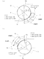
- (A) is explanatory drawing which shows the contact state of the inner ring
- (b) is explanatory drawing which shows the contact state of the outward member and ball
- (A) is explanatory drawing which shows the effect
- (b) is explanatory drawing which shows the effect
- FIG. 10 is binarized by a luminance threshold value using image processing software. It is a longitudinal cross-sectional view which shows 4th Embodiment of the wheel bearing apparatus which concerns on this invention. It is a longitudinal cross-sectional view which shows the conventional wheel bearing apparatus.
- FIG. 15 is an explanatory diagram enlarging a main part of FIG. 14, in which (a) shows when the vehicle is traveling straight, and (b) shows when the vehicle is turning.
- a vehicle body mounting flange to be attached to the vehicle body on the outer periphery, an outer member integrally formed with a double row outer rolling surface on the inner periphery, and a wheel mounting flange on one end.
- a hub wheel having one inner rolling surface facing the outer rolling surface of the double row on the outer periphery, a small-diameter step portion extending in the axial direction from the inner rolling surface, and a small-diameter step portion of the hub ring;
- An inner member composed of an inner ring that is press-fitted through a predetermined scissors and has the other inner rolling surface facing the double-row outer rolling surface on the outer periphery, and can freely roll between both rolling surfaces.
- a plurality of rows of balls provided with a predetermined contact angle, and a predetermined bearing preload is applied by a crimped portion formed by plastically deforming an end portion of the small diameter step portion radially outward.
- the inner rolling surface is formed in an arc shape having two radii of curvature, and the inner rolling surface is formed from the vicinity of the contact point in contact with the ball at the initial contact angle ⁇ to the groove bottom.
- a radius r1, and the curvature radii r and r1 are set in a range of 1.05d ⁇ 2r ⁇ 1.10d and 1.01d ⁇ 2r1 ⁇ 1.05d with respect to the diameter d of the ball.
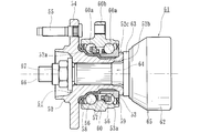
- FIG. 1 is a longitudinal sectional view showing a first embodiment of a wheel bearing device according to the present invention
- FIG. 2A is an explanatory view showing a contact state between an inner ring and a ball in FIG. 1, and FIG. It is explanatory drawing which shows the contact state of the outward member of FIG. 1, and a ball
- the side closer to the outside of the vehicle in the state assembled to the vehicle is referred to as an outer side (left side in FIG. 1), and the side closer to the center is referred to as an inner side (right side in FIG.
- This wheel bearing device is called a third generation on the driven wheel side, and includes an inner member 1 and an outer member 10, and double-row balls 6 and 6 accommodated so as to roll between both members 1 and 10. It has.
- the inner member 1 includes a hub ring 2 and a separate inner ring 3 that is externally fitted to the hub ring 2.
- the hub wheel 2 integrally has a wheel mounting flange 4 for mounting a wheel (not shown) at an end on the outer side, and the wheel mounting flange 4 is for fixing the wheel at a circumferentially equidistant position.
- Hub bolts 5 are planted.
- a circular hole 4 a is formed between the hub bolts 5 of the wheel mounting flange 4.
- the hub wheel 2 can be reduced in weight by the circular hole 4a, and in the assembly process of the wheel bearing device, for example, with the brake rotor (not shown) fixed to the hub wheel 2, the brake rotor and the wheel mounting flange 4
- the knuckle bolt (not shown) can be easily fastened with a tool without being obstructed by the tool, and the outer member 10 can be easily fixed to the knuckle (not shown) to improve the assembly workability. Can do.
- an outer side (one) inner rolling surface 2a and a small-diameter step portion 2b extending in the axial direction from the inner rolling surface 2a are formed on the outer periphery of the hub wheel 2.
- the inner ring 3 having the inner raceway surface 3a formed on the outer periphery is press-fitted into the small-diameter step portion 2b via a predetermined shimeiro, and the end portion of the small-diameter step portion 2b is plastically deformed radially outward.
- the inner ring 3 is fixed to the hub ring 2 in the axial direction in a state where a predetermined bearing preload is applied by the caulking portion 2c.
- the outer member 10 integrally has a vehicle body mounting flange 10b for mounting to a vehicle body (not shown) on the outer periphery, and a double row outer rolling surface 10a facing the inner rolling surfaces 2a and 3a on the inner periphery. 10a are integrally formed. And the double-row balls 6 and 6 are accommodated so as to be able to roll through the cages 7 and 7 with the initial contact angle ⁇ between the respective rolling surfaces 10a, 2a and 10a and 3a. Yes. Seals 8 and 9 are attached to the opening of the annular space formed between the inner member 1 and the outer member 10 to prevent leakage of the lubricating grease sealed inside the bearing and from the outside. It prevents rainwater and dust from entering the bearing.
- the wheel hub 2 is made of medium and high carbon steel containing 0.40 to 0.80% by weight of carbon, such as S53C, and is mounted on a wheel that forms a seal land portion in which the seal 8 comes into sliding contact with the inner rolling surface 2a on the outer side
- the surface hardness is set in the range of 58 to 64 HRC by induction hardening from the base portion 4b on the inner side of the flange 4 to the small diameter step portion 2b.
- the caulking portion 2c is an unquenched portion having a surface hardness of 25HRC or less after forging.
- the inner ring 3 is made of high carbon chrome bearing steel such as SUJ2, and is hardened in the range of 58 to 64 HRC to the core part by quenching.
- the outer member 10 is made of medium-high carbon steel containing 0.40 to 0.80% by weight of carbon such as S53C, and the double row outer rolling surfaces 10a and 10a have a surface hardness of 58 to 64 HRC by induction hardening. It has been cured to the extent of.
- the wheel bearing device referred to as the third generation in which the inner raceway surface 2a is formed directly on the outer periphery of the hub wheel 2 is illustrated, but the wheel bearing device according to the present invention is limited to such a structure.
- a first generation or second generation structure in which a pair of inner rings are press-fitted into a small-diameter step portion of a hub ring, or an inner rolling surface on the outer periphery of an outer joint member of a hub ring and a constant velocity universal joint, respectively. May be a wheel bearing device of the fourth generation structure in which is directly formed.
- the inner raceway surface 3a of the inner ring 3 is formed in an arc shape having two curvature radii. That is, the inner raceway surface 3a of the inner ring 3 has a radius of curvature r formed from the vicinity of the contact point P in contact with the ball 6 at the initial contact angle ⁇ to the groove bottom, and from the vicinity of the contact point P. It is comprised with the curvature radius r1 formed over the large outer diameter 3b.
- the initial contact angle ⁇ is appropriately set in the range of 30 to 45 ° depending on the load condition of the vehicle and the bearing space.
- the radius of curvature r is set to be larger than the radius of curvature r1, and 1.05d ⁇ 2r ⁇ 1.10d, preferably 1.05d ⁇
- the range is set to 2r ⁇ 1.08d.
- the radius of curvature r1 is set to a range of 1.01d ⁇ 2r1 ⁇ 1.05d, preferably 1.03d ⁇ 2r1 ⁇ 1.05d with respect to the diameter d of the ball 6.
- the outer rolling surface 10a of the outer member 10 is also formed in an arc shape composed of two curvature radii r2 and r3. That is, the outer rolling surface 10a of the outer member 10 has a radius of curvature r2 formed from the vicinity of the contact point Q that contacts the ball 6 at the initial contact angle ⁇ to the groove bottom, and the contact point Q.
- the radius of curvature r3 is formed from the vicinity to the inner diameter 10c.
- the curvature radius r2 is set to be larger than the curvature radius r3, and 1.07d ⁇ 2r2 ⁇ 1.12d, preferably 1.07d ⁇
- the range is set to 2r2 ⁇ 1.10d.
- the radius of curvature r3 is set to a range of 1.03d ⁇ 2r3 ⁇ 1.07d, preferably 1.05d ⁇ 2r3 ⁇ 1.07d with respect to the diameter d of the ball 6.
- the respective preload amounts are set in a range of 0 to 10 ⁇ m when traveling straight (contact points P and Q) and 10 to 50 ⁇ m when turning (contact points P0 and Q0).
- the preload applied in the initial stage is ensured, and excessive preload can be suppressed to prevent an increase in rolling resistance, and at the time of turning of the vehicle loaded with moment load, Accordingly, the preload amount can be increased, and the bearing rigidity can be increased and the durability can be improved without adding any parts.
- the thing which comprised the rolling surface of both the double row inner side rolling surfaces 2a and 3a of the inner member 1 and the double row outer side rolling surfaces 10a and 10a of the outer member 10 with two curvature radii, respectively is illustrated.
- the double row inner raceway surfaces 2a and 3a side of the inner member 1 having a strong influence on the bearing rigidity and life at least be configured with these two curvature radii r and r1.
- the inner rolling surface 2a is formed in an arc shape having two curvature radii, and these two different curvature radii r.
- the processing method will be described by taking the inner raceway surface 3a of the inner ring 3 as an example.
- the inner rolling surface 3a is composed of a plurality of radii of curvature r and r1
- grinding has been performed by a grinding wheel previously formed into the shape of the inner rolling surface 3a.
- a plurality of forming grindstones must be prepared.
- after heat treatment turning is performed (hardened steel cutting) with a carbide tip (not shown).
- the carbide tip is supported so as to be movable forward and backward in the radial direction and movable in the axial direction, and its position is determined by NC control. Thereby, manufacturing cost including management cost can be reduced, and cost reduction can be achieved.
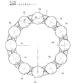
- FIG. 3 is a front view showing one bearing row in a second embodiment of the wheel bearing device according to the present invention
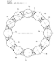
- FIG. 4 is a front view showing a modification of FIG. 3
- FIG. It is a front view which shows another modification. Note that this embodiment is basically different from the first embodiment described above only in the configuration of the balls, and other parts and parts having the same parts or parts having the same functions are denoted by the same reference numerals. The detailed explanation is omitted.
- the balls 6 and 6 in each row of the wheel bearing device are accommodated in a state where the large-diameter balls 6a and the small-diameter balls 6b are mixed. That is, the large-diameter balls 6a and the small-diameter balls 6b are alternately arranged with regularity.
- the radial load is loaded only with the large-diameter ball 6a, and thus the rolling resistance is reduced and the rotational torque can be reduced.
- each rolling surface is formed in an arc shape having two radii of curvature
- the preload applied in the initial stage is ensured, and an excessive preload can be suppressed to prevent an increase in rolling resistance, and the moment When turning a vehicle with a load on it, the amount of preload is increased accordingly, and it is not affected by variations in processing, etc., so that the torque during straight running of the vehicle can be reduced and the bearing life during turning is improved. It is possible to provide a wheel bearing device that achieves the above.
- the large-diameter balls 6a and the small-diameter balls 6b are alternately arranged is illustrated, but not limited thereto, for example, as shown in FIG. 4, the large-diameter balls 6a, the small-diameter balls 6b, 6b, and the large-diameter As shown in FIG. 5, it is also possible to arrange large balls 6a, 6a, small balls 6b, large balls 6a, 6a,. . As a result, it is possible to deal with the frequency of straight travel and turning of the vehicle, or the relationship between the load condition and the load capacity of the bearing, and the degree of freedom in design is expanded.
- the contact ellipse of the ceramic ball is smaller because it is more rigid than the steel ball. Accordingly, the torque can be reduced by making all the balls 6 and 6 in the double row ceramic balls, but the ceramic balls are more expensive than the steel balls, which is not preferable because the cost increases. For this reason, for example, of the double row balls 6 and 6, the inner side ball row to which a large load is applied when a moment load is applied during turning of the vehicle is a ceramic ball, and the outer side ball row By using a steel ball, torque can be reduced and bearing life can be improved without significant cost increase.
- each ball 6 in one row has a low torque even if ceramic balls are mixed instead of the large-diameter balls 6a in the same manner as the configuration in which the large-diameter balls 6a and the small-diameter balls 6b are mixed. And improvement of bearing life.
- FIG. 6 is a schematic diagram showing one of the bearing rows in a third embodiment of the wheel bearing device according to the present invention
- FIG. 7A is an explanatory view showing an action during straight traveling and turning of the vehicle
- (B) is an explanatory view showing the action of the vehicle when traveling straight at low speed and when traveling straight at high speed
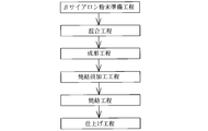
- FIG. 8 is a schematic diagram showing a method for producing a ceramic ball according to the present invention
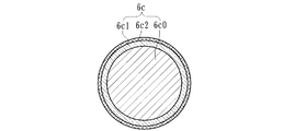
- FIG. FIG. 10 is a schematic view showing a cross section of a ball
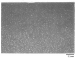
- FIG. 10 is a photograph of a cross section for observation of a test piece of a ceramic ball according to the present invention taken by oblique light of an optical microscope
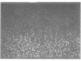
- FIG. 11 is an image of the photograph of FIG. FIG.
- FIG. 12 illustrates an example of a state in which binarization processing is performed using a luminance threshold using processing software.
- FIG. 12 illustrates image processing when the image of the photograph in FIG. 10 is binarized using luminance threshold using image processing software. It is a figure which shows the area
- a steel ball 6 made of high carbon chrome steel such as SUJ2 and a ceramic ball 6c (cross hatching in the figure).
- the ceramic ball 6c is composed of a ⁇ sialon sintered body. Ceramics made of silicon nitride, sialon, and the like are higher in manufacturing cost than steel, and in recent years, ⁇ sialon sintered bodies have attracted attention as components of rolling bearings (for example, Japanese Patent Application Laid-Open Nos. 2004-91272 and 2005). -75652, JP-A-2005-194154).
- this ⁇ sialon sintered body is represented by a composition formula of Si 6 -zAlzOzN 8 -z, and a sintered body comprising ⁇ sialon as a main component satisfying 0.1 ⁇ z ⁇ 3.5 and the remaining impurities. Consists of union.
- the impurities include irreversible impurities including those derived from raw materials or those mixed in the manufacturing process.
- the ceramic ball 6c is composed of ⁇ sialon represented by a composition formula of Si 6 -zAlzOzN 8 -z and satisfying 0.1 ⁇ z ⁇ 3.5 as a main component, and from the remaining sintering aid and irreversible impurities. You may be comprised with the sintered compact which becomes.
- a sintering aid it is possible to select at least one of magnesium (Mg), aluminum (Al), silicon (Si), titanium (Ti), rare earth element oxide, nitride and oxynitride. it can. Further, the sintering aid is desirably 20% by mass or less in the sintered body.
- This sintered body can be manufactured with various compositions in which the above-described z value (hereinafter referred to as z value) is 0.1 or more, but generally has a great influence on the rolling fatigue life.
- the surface hardness that gives the same hardly changes in the range of the z value of 4.0 or less which is easy to manufacture.
- the ceramic made of a sintered body containing ⁇ sialon as a main component which will be described later. In the ball 6c, it was found that when the z value exceeds 3.5, the rolling fatigue life is significantly reduced.
- the rolling fatigue life is almost the same, and if the rolling bearing operating time exceeds a predetermined time, it peels off on the surface of the ceramic ball 6c. Will occur and lead to damage.
- the z value exceeds 3.5 the ceramic balls 6c are likely to be worn, and the rolling fatigue life is significantly reduced due to this. That is, it has been clarified that when the z value exceeds 3.5, the rolling fatigue life is significantly reduced.
- Table 1 shows a comparison of the characteristics of silicon nitride, high carbon chromium steel (SUJ2), and ⁇ sialon sintered bodies that are the raw materials of the double row balls 6 and 6c.
- the silicon nitride and ⁇ sialon sintered body have higher Young's modulus and surface hardness than the high carbon chromium steel, and the linear expansion coefficient is remarkably small. That is, when it is adopted as a material for the double-row balls 6 and 6, high rigidity can be obtained and a dimensional change amount when the temperature of the bearing is raised can be suppressed.
- ceramic balls have different characteristics including a linear expansion coefficient compared to ordinary steel balls, and the balls 6 and 6 of at least one of the left and right bearing rows are By arranging the steel balls 6 and the ceramic balls 6c in a mixed state, in addition to the effect that each rolling surface is formed in an arc shape having two radii of curvature, the rolling resistance when the vehicle is traveling straight ahead is reduced. It is possible to provide a wheel bearing device that suppresses and achieves improved bearing life by increasing rigidity at high loads such as turning.
- the diameter difference between the steel ball 6 and the ceramic ball 6c is different.
- D ⁇ d3 in the initial state and the load is applied only by the ceramic balls 6c. Since the ceramic ball 6c has a smaller amount of elastic deformation when a load is applied than the steel ball 6, the rolling resistance can be suppressed and the bearing torque can be reduced while securing the initial bearing preload.
- the temperature rise of the bearing can be suppressed, and deterioration of the grease can be suppressed and the bearing life can be improved.
- the steel ball 6 is made of the ceramic ball 6c due to the difference in coefficient of linear expansion between the steel ball 6 and the ceramic ball 6c. Compared to the above, the initial diameter difference disappears and d ⁇ d3. Therefore, the load is applied by both the steel ball 6 and the ceramic ball 6c, and the high rigidity of the bearing can be achieved.
- the difference ⁇ d between the outer diameters of the steel ball 6 and the ceramic ball 6c is, for example, an expansion of about 1 ⁇ m / 10 ° C. between the steel ball 6 and the ceramic ball 6c when the nominal size of the ball 6 is 1/2 inch.
- a temperature increase range of 50 to 100 ° C. can be allowed. If the diameter difference is less than 5 ⁇ m, it is difficult to achieve the effect, and if it exceeds 10 ⁇ m, there is a possibility that only the ceramic balls 6 c are loaded in any mode, which is not preferable.
- the ratio of the mixed loading of the steel balls 6 and the ceramic balls 6c varies depending on the mode of the vehicle and the specifications of the bearing, for example, the odd number and the even number, but includes 1: 1 to 3: 7 to 7: 3.
- the range of is preferable. This is because if the ratio of the steel ball 6 and the ceramic ball 6c is 2: 8 or less, the cost is increased, and if it is 8: 2 or more, it is not possible to reduce the torque and improve the rigidity of the bearing.
- the load conditions are severe.
- the inner-side balls 6 row is 3: 7 and the outer-side balls 6 row is 7: 3.
- the applicant of the present invention can manufacture a sintered body of ⁇ sialon by sintering it under a pressure of 1 MPa or less, thereby making it possible to stably ensure sufficient durability.
- ⁇ sialon powder preparation step for example, ⁇ sialon powder can be produced at low cost by a production step employing a sintering synthesis method.
- a mixing step is performed in which the ⁇ sialon powder prepared in the ⁇ sialon powder preparation step and the sintering aid are added and mixed. This mixing step can be omitted when no sintering aid is added.
- a molding step is performed in which a mixture of the ⁇ sialon powder and the sintering aid is molded into the general shape of the ceramic ball 6c.
- a molding technique such as press molding, casting molding, extrusion molding, rolling granulation, etc.
- the shape of the ceramic ball 6c is approximated.
- a molded product is produced.
- a pre-sintering processing step is performed in which the surface of the formed body is processed to form a shape close to a desired ball shape after sintering. Specifically, by applying a processing method such as green body processing, the green body is shaped so as to be closer to the ball shape. This pre-sintering processing step can be omitted if a shape closer to the desired ball shape is obtained after sintering at the stage where the formed body is formed in the forming step.
- a sintering process is performed in which the compact is sintered under a pressure of 1 MPa or less.
- the compact is heated and sintered by a heating method such as heater heating, electromagnetic wave heating using microwaves or millimeter waves, etc., so that a substantially spherical sintered body is produced.
- Sintering is performed by heating the compact to a temperature range of 1550 ° C. or higher and 1800 ° C. or lower in an inert gas atmosphere or a mixed gas atmosphere of nitrogen and oxygen.
- the step of sintering the molded body made of ⁇ sialon it is performed in a temperature range of 1550 ° C. or higher and 1800 ° C. or lower.
- the temperature at which bonding is performed is preferably 1550 ° C. or higher.
- the temperature exceeds 1800 ° C. there is a concern that the mechanical properties of the sintered body may be deteriorated due to the coarsening of ⁇ -sialon crystal grains.
- the inert gas helium, neon, argon, nitrogen, or the like can be employed, but nitrogen is preferably employed from the viewpoint of reducing manufacturing costs.
- the surface of the sintered body produced in the sintering process is processed, and a finishing process for removing the region including the surface is performed, whereby a finishing process for completing the ceramic ball 6c is performed.
- the surface of the sintered body produced in the sintering process is finished into a desired shape / dimension or surface roughness by grinding and lapping.
- a region having a thickness of about 500 ⁇ m from the surface of the sintered body is denser than the inside 6c0, as shown schematically in FIG.
- a dense layer 6c1 in which the area ratio of the white region observed as a white region is 7% or less is formed. That is, a low porosity (high density) layer is formed in the sintered body.
- the region having a thickness of about 150 ⁇ m from the surface of the sintered body has a higher density than the other regions in the dense layer, and is observed as a white region when the cross section is observed with an oblique light of an optical microscope.
- a highly dense layer 6c2 in which the area ratio of the white region is 3.5% or less is formed. Therefore, in the finishing step, it is preferable that the thickness of the sintered body to be removed is 150 ⁇ m or less particularly in the region to be the rolling surface. Thereby, the highly dense layer 6c2 can remain, and the rolling fatigue life of the ceramic balls 6c can be improved.
- the present applicant produces a deep groove ball bearing having ceramic balls when it is made of a ⁇ sialon sintered body having various values among the z values described above, and shows the relationship between the z value and the rolling fatigue life (durability).
- a test to verify was conducted. The test procedure is as follows.
- ⁇ sialon powder prepared by a sintering synthesis method with a z value in the range of 0.1 to 4.0 was prepared, and the same method as the ceramic ball manufacturing method described above with reference to FIG. 8 was used. Ceramic balls having a z value of 0.1 to 4.0 were produced. Specifically, first, ⁇ sialon powder refined to submicron, aluminum oxide (manufactured by Sumitomo Chemical Co., Ltd., AKP30) and yttrium oxide (manufactured by HC Starck, Yttrium oxide) as sintering aids. grade C) was mixed by wet mixing using a ball mill.
- granulation was performed with a spray dryer to produce granulated powder.
- the granulated powder was molded into a sphere with a mold, and further pressed by cold isostatic pressing (CIP) to obtain a spherical molded body.
- CIP cold isostatic pressing
- test conditions will be described.
- maximum contact surface pressure Pmax 3.2 GPa
- bearing rotation speed 2000 rpm
- lubrication circulating oil supply of turbine oil VG68 (clean oil)
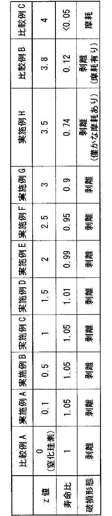
- test temperature A fatigue test was carried out under the condition of room temperature. Then, the vibration of the bearing during operation is monitored by the vibration detection device, and the test is stopped when each ball is damaged and the vibration of the bearing exceeds a predetermined value. Recorded as bearing life. In addition, after the test was stopped, the bearings were disassembled and the damaged state of each ball was confirmed. The results are shown in Table 2.
- the life in each Example and Comparative Example is expressed as a life ratio with the life in Comparative Example A (silicon nitride) as 1. Further, the failure mode is described as “peeling” when peeling occurs on the surface of the ball, and “wearing” when the surface is worn without peeling and the test is stopped.
- Examples A to H of the present invention in which the z value is 0.1 or more and 3.5 or less have a life comparable to that of Comparative Example A. Further, the form of breakage is “peeling” as in the case of silicon nitride.
- Comparative Example B in which the z value exceeds 3.5 and is outside the scope of the present invention, the life is significantly reduced and wear is observed on the ball. That is, it is considered that the life of the ball is greatly reduced due to the wear of the ball.
- Comparative Example C where the z value is 4.0 it can be seen that the wear of the ball proceeds in a very short time, and the durability of the bearing is significantly reduced.
- the durability of the rolling bearing provided with the ball made of ⁇ sialon sintered body is provided with the ball made of sintered silicon nitride. It can be seen that it is almost equivalent to a rolling bearing.
- the z value exceeds 3.5 the ball is likely to be worn, and the rolling fatigue life is significantly reduced due to this.
- the cause of breakage of the ball made of ⁇ sialon changes from “peeling” to “wear”, and the rolling fatigue life is significantly reduced. That is, by setting the z value to 0.1 or more and 3.5 or less, it is possible to stably ensure sufficient durability while being inexpensive.
- Example H in which the z value exceeds 3.5, the ball is slightly worn, and the life is also reduced compared to Examples A to G. Yes. From this, it can be said that the z value is desirably 3 or less in order to ensure sufficient durability stably.
- the z value is preferably 2 or less, and more preferably 1.5 or less.
- test procedure is as follows.
- a ⁇ sialon powder product name: Meramix, manufactured by Isman Jay Co., Ltd.
- a composition produced by the sintering synthesis method is Si 5 AlzON 7
- a cubic test piece having a side of approximately 10 mm was produced.
- a specific manufacturing method is as follows.
- ⁇ sialon powder refined to submicron aluminum oxide (manufactured by Sumitomo Chemical Co., Ltd., AKP30) and yttrium oxide (manufactured by HC Starck, Yttrium oxide grade C) as sintering aids.
- Mixing was performed by wet mixing using a ball mill.
- granulation was performed with a spray dryer to produce granulated powder.
- the granulated powder was molded into a sphere with a mold, and further pressurized with CIP to obtain a spherical molded body.
- the molded body was heated and sintered at 1650 ° C. in a nitrogen atmosphere at a pressure of 4 MPa to prepare a cubic test piece. Thereafter, the test piece was cut, and the cut surface was lapped with a diamond lapping machine, and then mirror lapping with a chromium oxide lapping machine was performed to form a cross section for observation including the center of the cube. Then, the cross section was observed with an oblique light of an optical microscope (Nikon Corporation, Micro Photo-FXA), and an instant photograph (FP-100B, Fuji Film Co., Ltd.) with a magnification of 50 times was taken. Thereafter, the obtained photographic image was taken into a personal computer using a scanner (resolution: 300 DPI). And the binarization process by a brightness
- FIG. 10 is a photograph of a cross section for observing the test piece taken with oblique light from an optical microscope.
- FIG. 11 is an example showing a state in which the image of the photograph of FIG. 10 is binarized using a luminance threshold using image processing software.
- FIG. 12 is a diagram showing an area (evaluation area) where image processing is performed when the image of the photograph of FIG. 10 is binarized using a luminance threshold using image processing software.
- the upper side of the photograph is the surface side of the test piece, and the upper end is the surface.
- the test piece produced by the same manufacturing method as the sphere of the present invention has a layer with less white area than the inside in the area including the surface.
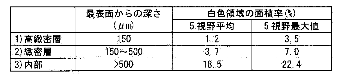
- the photographed photograph image is divided into three regions according to the distance from the outermost surface of the test piece (the region having a distance from the outermost surface of 150 ⁇ m or less, the region exceeding 150 ⁇ m and within 500 ⁇ m,
- the area ratio of the white region was calculated by performing image analysis for each region, the results shown in Table 3 were obtained.
- Table 3 shows the average value and the maximum value of the area ratio of the white area in five fields of view obtained from five photographs taken at random with each field shown in FIG. 12 as one field of view. Yes.
- the area ratio of the white region was 18.5% inside, whereas the region where the depth from the surface was 500 ⁇ m or less was 3.7%, the depth from the surface. was 1.2% in the region of 150 ⁇ m or less. From this, it was confirmed that in the test piece, a dense layer and a highly dense layer having a white region less than the inside were formed in the region including the surface.
- the area ratio of the white region was 18.5% inside, whereas the region where the depth from the surface was 500 ⁇ m or less was 3.7%, the depth from the surface. was 1.2% in the region of 150 ⁇ m or less. From this, it was confirmed that in the test piece, a dense layer and a highly dense layer having a white region less than the inside were formed in the region including the surface.
- Granulation was carried out with a lay drier to produce granulated powder. The granulated powder was molded into a sphere with a mold, and further pressurized with CIP to obtain a spherical molded body.
- the green body is green processed so that the processing allowance after sintering becomes a predetermined dimension, and the green body is subsequently heated to 1650 ° C. in a nitrogen atmosphere at a pressure of 0.4 MPa to be sintered.
- sintered spheres were produced.
- lapping processing was performed on the sintered sphere to obtain a 3/8 inch ceramic sphere (JIS grade G5).
- the deep groove ball bearing of JIS standard 6206 model number was produced in combination with the bearing ring made from bearing steel (JIS standard SUJ2) prepared separately.
- the thickness (processing allowance) of the sintered sphere removed by the lapping process on the sintered sphere was changed in eight stages, and eight types of bearings were produced (Examples A to H).
- test conditions will be described.
- the maximum contact surface pressure Pmax 3.2 GPa
- the bearing rotation speed 2000 rpm
- lubrication circulating oil supply of turbine oil VG68 (clean oil)
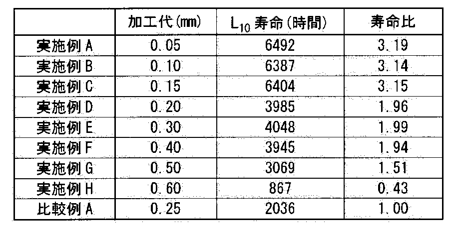
- test temperature A fatigue test was carried out under the condition of room temperature. Then, the vibration of the bearing during operation is monitored by the vibration detection device, and the test is stopped when each ball is damaged and the vibration of the bearing exceeds a predetermined value. Recorded as bearing life. The number of tests was 15 in each of the examples and comparative examples, and the L 10 life was calculated, and the durability was evaluated by the life ratio with respect to comparative example A. Table 4 shows the test results.
- the L 10 life individually when operating under the same conditions a group of identical bearings, total number of revolutions of 90% of the bearings of which can be rotated without causing damage due to rolling fatigue of materials, or constant rotational Speed refers to the total rotation time.
- the bearing life of each example is good in view of its manufacturing cost. Further, by setting the machining allowance to 0.5 mm or less, the bearing life of Examples D to G in which the dense layer remains on the surface of the ball is about 1.5 to 2 times the bearing life of Comparative Example A. It was. Further, by setting the machining allowance to 0.15 mm or less, the bearing life of Examples A to C in which the highly dense layer remained on the surface of the ball was about three times that of Comparative Example A. From this, it was confirmed that the bearing provided with the ball of the present invention is excellent in durability.
- the life is improved by leaving the dense layer on the surface with the ball machining allowance of 0.5 mm or less, and the life is improved by leaving the high dense layer on the surface with the ball machining allowance of 0.15 mm or less. It was found that it improved further.
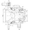
- FIG. 13 is a longitudinal sectional view showing a fourth embodiment of the wheel bearing device according to the present invention. It should be noted that the same reference numerals are used for the same parts of the same parts or parts having the same function, except that the pitch circle diameter of the double row of balls is basically different from the first embodiment (FIG. 1). The detailed description is omitted.
- This wheel bearing device is for a driven wheel called a third generation, and includes an inner member 11 and an outer member 12, and a double row of balls 13 accommodated so as to roll between the members 11 and 12. , 14 groups.
- the inner member 11 includes a hub ring 15 and an inner ring 16 press-fitted into the hub ring 15 via a predetermined shimiro.
- the hub wheel 15 integrally has a wheel mounting flange 17 for attaching a wheel (not shown) to an end portion on the outer side, one (outer side) inner rolling surface 15a on the outer periphery, and this inner rolling.
- a small-diameter step portion 15b is formed via a shaft-like portion 18 extending in the axial direction from the surface 15a.
- Hub bolts 5 are implanted in the wheel mounting flange 17 at equal intervals in the circumferential direction, and circular holes 4 a are formed between the hub bolts 5.
- the inner ring 16 is formed with the other (inner side) inner rolling surface 16a on the outer periphery and is press-fitted into the small-diameter stepped portion 15b of the hub wheel 15 to form a back-to-back type double row angular contact ball bearing.
- the end portion of 15b is fixed in the axial direction with a predetermined bearing preload applied by a caulking portion 2c formed by plastic deformation, thereby forming a so-called self-retain structure.
- the inner ring 16 and the rolling elements 13 and 14 are made of high carbon chrome steel such as SUJ2, and are hardened in the range of 58 to 64 HRC to the core portion by quenching.
- the hub wheel 15 is made of medium and high carbon steel containing 0.40 to 0.80 wt% of carbon such as S53C, and includes an inner rolling surface 15a and a base 4b on the inner side of the wheel mounting flange 17 to a small diameter step portion 15b.
- a predetermined curing process is performed in a surface hardness range of 58 to 64 HRC by induction hardening.
- the outer member 12 integrally has a vehicle body mounting flange 10b to be attached to a knuckle (not shown) on the outer periphery, and the outer side outer rolling facing the inner rolling surface 15a of the hub wheel 15 on the inner circumference.
- the surface 12a and the inner side outer rolling surface 12b facing the inner rolling surface 16a of the inner ring 16 are integrally formed. Double rows of balls 13 and 14 are accommodated between these rolling surfaces, and are held by the cages 19 and 20 so as to roll freely.
- a seal 21 and a slinger 22 are attached to the opening of the annular space formed between the outer member 12 and the inner member 11, and leakage of grease sealed inside the bearing to the outside Prevents rainwater and dust from entering the bearing.
- the outer member 12 is formed of medium and high carbon steel containing 0.40 to 0.80 wt% of carbon such as S53C, and the double row outer rolling surfaces 12a and 12b have a surface hardness of 58 to 64 HRC by induction hardening described later.
- a predetermined hardened layer is formed in the range.
- the wheel bearing device referred to as the third generation on the driven wheel side in which the inner rolling surface 15a is directly formed on the outer periphery of the hub wheel 15 is illustrated, but the wheel bearing device according to the present invention is It is not limited to such a structure, for example, a first generation or second generation structure in which a pair of inner rings is press-fitted into a small-diameter step portion of a hub ring, or an outer joint member of a hub ring and a constant velocity universal joint, respectively. It may be a fourth-generation wheel bearing device in which the inner rolling surface is directly formed.
- the pitch circle diameter PCDo of the outer side balls 13 group is set larger than the pitch circle diameter PCDi of the inner side balls 14 group (PCDo> PCDi).
- the number of the outer side balls 13 is set larger than the number of the inner side balls 14. Accordingly, the bearing space can be effectively utilized to reduce the weight and size, and the bearing rigidity of the outer side portion can be increased compared to the inner side, so that the life of the bearing can be extended.
- the outer ring of the hub wheel 15 has a counter part 23 from the groove bottom part of the inner rolling surface 15a, and a shoulder part 18b against which the inner ring 16 is abutted from the counter part 23 via a shaft-like part 18 and a tapered step part 18a. And it is formed in a shape following the small diameter step portion 15b. Further, a mortar-shaped recess 24 extending in the axial direction is formed at the outer side end of the hub wheel 15. This recess 24 is formed along the outer shape of the hub wheel 15 by forging, and its depth is at least near the groove bottom of the inner side rolling surface 15a on the outer side. The thickness is formed to be substantially uniform.
- the outer member 12 is formed such that the outer rolling surface 12a on the outer side has a larger diameter than the outer rolling surface 12b on the inner side due to the difference in pitch circle diameters PCDo and PCDi.
- An annular recess 27 for weight reduction is formed between the shoulder portion 25 of the running surface 12a and the shoulder portion 26 of the inner side outer rolling surface 12b which is the small diameter side.
- the inner raceway surface 16a and the outer raceway surface 12b of the inner ring 16 are formed in an arc shape composed of two curvature radii r, r1, r2, r3.
- the respective preload amounts are set in a range of 0 to 10 ⁇ m when traveling straight (contact points P and Q) and 10 to 50 ⁇ m when turning (contact points P0 and Q0).
- the preload applied in the initial stage is ensured, and excessive preload can be suppressed to prevent an increase in rolling resistance, and at the time of turning of the vehicle loaded with moment load, Accordingly, the preload amount can be increased, and the bearing rigidity can be increased and the durability can be improved without adding any parts.
- the same configuration as in the second or fourth embodiment may be adopted.
- the wheel bearing device according to the present invention can be applied to a wheel bearing device having a first generation to a fourth generation structure constituted by a double row angular ball bearing.
Landscapes
- Engineering & Computer Science (AREA)
- General Engineering & Computer Science (AREA)
- Mechanical Engineering (AREA)
- Ceramic Engineering (AREA)
- Manufacturing & Machinery (AREA)
- Rolling Contact Bearings (AREA)
Abstract
Description
図1は、本発明に係る車輪用軸受装置の第1の実施形態を示す縦断面図、図2(a)は、図1の内輪とボールの接触状態を示す説明図、(b)は、図1の外方部材とボールの接触状態を示す説明図である。なお、以下の説明では、車両に組み付けた状態で車両の外側寄りとなる側をアウター側(図1の左側)、中央寄り側をインナー側(図1の右側)という。

2、15 ハブ輪
2a、3a、15a、16a 内側転走面
2b、15b 小径段部
2c 加締部
3、16 内輪
3b 大外径
4、17 車輪取付フランジ
4a 円孔
4b 基部
5 ハブボルト
6、13、14 ボール
6a 大径ボール
6b 小径ボール
6c セラミック製ボール
6c0 内部
6c1 緻密層
6c2 高緻密層
7、19、20 保持器
8、9、21 シール
10、12 外方部材
10a、12a、12b 外側転走面
10b 車体取付フランジ
10c 内径
18 軸状部
18a 段部
18b、25、26 肩部
22 スリンガ
23 カウンタ部
24、27 凹所
51 内方部材
52 ハブ輪
52a、53a 内側転走面
52b 小径段部
52c 加締部
53 内輪
53b 大外径
54 車輪取付フランジ
55 ハブボルト
56 ボール
57 保持器
58、59 シール
60 外方部材
60a 外側転走面
60b 車体取付フランジ
60c 内径
61 等速自在継手
62 マウス部
63 肩部
64 軸部
65 外側継手部材
66 雄ねじ
67 固定ナット
d 鋼球の直径
d1 大径ボールの直径
d2 小径ボールの直径
d3 セラミック製ボールの直径
Δd 直径の径差
P、P1 内側転走面とボールの接触点
P0 内側転走面の変曲点
PCDi インナー側のボール群のピッチ円直径
PCDo アウター側のボール群のピッチ円直径
Q、Q1 外側転走面とボールの接触点
Q0 外側転走面の変曲点
r、r1 内側転走面の曲率半径
r2、r3 外側転走面の曲率半径
α 初期の接触角
α1 接触角
Δα 接触角の増加量
Claims (18)
- 内周に複列の外側転走面が一体に形成された外方部材と、
外周にこれら複列の外側転走面に対向する複列の内側転走面が形成された内方部材と、
前記両転走面間に転動自在に収容され、所定の接触角が付与された複列のボールとを備えた車輪用軸受装置において、
前記両転走面のうち少なくとも前記内側転走面が2つの曲率半径からなる円弧状に形成され、当該内側転走面が、初期の接触角αにて前記ボールと接触する接触点の近傍から溝底に亙って形成された曲率半径rと、この曲率半径rよりも小さく、接触角α1にて前記ボールと接触する変曲点から外径側に亙って形成された曲率半径r1とで構成され、前記ボールの直径dに対して、前記曲率半径r、r1が、1.05d<2r≦1.10dおよび1.01d≦2r1≦1.05dの範囲に設定されると共に、これら異なる2つの曲率半径r、r1の前記変曲点を、α=30~45°で、α1=α+Δαとした時、Δαが、2~8°の範囲に設定されていることを特徴とする車輪用軸受装置。 - 前記複列のボール群のうちアウター側のボール群のピッチ円直径がインナー側のボール群のピッチ円直径よりも大径に設定されている請求項1に記載の車輪用軸受装置。
- 前記外側転走面が2つの曲率半径からなる円弧状に形成され、当該外側転走面が、初期の接触角αにて前記ボールと接触する接触点の近傍から溝底に亙って形成された曲率半径r2と、この曲率半径r2よりも小さく、接触角α1にて前記ボールと接触する変曲点から前記外方部材の内径に亙って形成された曲率半径r3とで構成され、前記ボールの直径dに対して、前記曲率半径r2、r3が、1.07d<2r2≦1.12dおよび1.03d≦2r3≦1.07dの範囲に設定されている請求項1または2に記載の車輪用軸受装置。
- 前記転走面が熱処理後に焼入れ鋼切削によって所定の仕上げ形状に形成されている請求項1乃至3いずれかに記載の車輪用軸受装置。
- 前記予圧量が、車両の直進時において0~10μm、旋回時において10~50μmの範囲に設定されている請求項1乃至4いずれかに記載の車輪用軸受装置。
- 前記複列のボール列のボールが、大径ボールと小径ボールとが交互に規則性を持って配列されている請求項1乃至5いずれかに記載の車輪用軸受装置。
- 前記大径ボールと小径ボールとの径差が5~10μmの範囲に設定されている請求項6に記載の車輪用軸受装置。
- 前記複列のボール列のボールがセラミック製ボールと鋼球とで構成されている請求項1乃至5いずれかに記載の車輪用軸受装置。
- 前記複列のボール列のうち、車両の旋回時、モーメント荷重が負荷された時に大きな荷重が負荷されるボール列のみがセラミック製ボールとされ、他方のボール列が鋼球とされている請求項8に記載の車輪用軸受装置。
- 前記複列のボール列のボールが、セラミック製ボールと鋼球とが交互に規則性を持って配列されている請求項8に記載の車輪用軸受装置。
- 前記複列のボール列のボールが、大径ボールと小径ボールとが交互に規則性を持って配列され、前記大径ボールがセラミック製ボールで構成されている請求項8に記載の車輪用軸受装置。
- 前記セラミック製ボールが、Si6-zAlzOzN8-zの組成式で表され、0.1≦z≦3.5を満たすβサイアロンを主成分とし、残部不純物からなる焼結体で構成されている請求項8乃至11いずれかに記載の車輪用軸受装置。
- 前記セラミック製ボールが、Si6-zAlzOzN8-zの組成式で表され、0.1≦z≦3.5を満たすβサイアロンを主成分とし、残部焼結助剤および不可逆的不純物からなる焼結体で構成されている請求項8乃至11いずれかに記載の車輪用軸受装置。
- 前記鋼球とセラミック製ボールの混載の割合が1:1を含む3:7~7:3までの範囲に設定されている請求項8、12および13いずれかに記載の車輪用軸受装置。
- 前記セラミック製ボールの表面に内部よりも緻密性の高い層である緻密層が形成されている請求項8乃至14いずれかに記載の車輪用軸受装置。
- 前記緻密層の断面を光学顕微鏡の斜光にて観察した場合、白色の領域として観察される白色領域の面積率が7%以下に設定されている請求項15に記載の車輪用軸受装置。
- 前記緻密層の表面を含む領域に、前記緻密層内の他の領域よりもさらに緻密性の高い層である高緻密層が形成されている請求項15または16に記載の車輪用軸受装置。
- 前記高緻密層の断面を光学顕微鏡の斜光にて観察した場合、白色の領域として観察される白色領域の面積率が3.5%以下に設定されている請求項17に記載の車輪用軸受装置。
Priority Applications (3)
| Application Number | Priority Date | Filing Date | Title |
|---|---|---|---|
| CN200980149411.4A CN102245915B (zh) | 2008-12-09 | 2009-12-08 | 车轮用轴承装置 |
| DE112009003533.7T DE112009003533B4 (de) | 2008-12-09 | 2009-12-08 | Radlagervorrichtung für ein Fahrzeug |
| US13/155,501 US8678661B2 (en) | 2008-12-09 | 2011-06-08 | Wheel bearing apparatus for a vehicle |
Applications Claiming Priority (4)
| Application Number | Priority Date | Filing Date | Title |
|---|---|---|---|
| JP2008-313439 | 2008-12-09 | ||
| JP2008-313438 | 2008-12-09 | ||
| JP2008313438A JP5261157B2 (ja) | 2008-12-09 | 2008-12-09 | 車輪用軸受装置 |
| JP2008313439A JP2010138940A (ja) | 2008-12-09 | 2008-12-09 | 車輪用軸受装置 |
Related Child Applications (1)
| Application Number | Title | Priority Date | Filing Date |
|---|---|---|---|
| US13/155,501 Continuation US8678661B2 (en) | 2008-12-09 | 2011-06-08 | Wheel bearing apparatus for a vehicle |
Publications (1)
| Publication Number | Publication Date |
|---|---|
| WO2010067586A1 true WO2010067586A1 (ja) | 2010-06-17 |
Family
ID=42242579
Family Applications (1)
| Application Number | Title | Priority Date | Filing Date |
|---|---|---|---|
| PCT/JP2009/006700 Ceased WO2010067586A1 (ja) | 2008-12-09 | 2009-12-08 | 車輪用軸受装置 |
Country Status (4)
| Country | Link |
|---|---|
| US (1) | US8678661B2 (ja) |
| CN (1) | CN102245915B (ja) |
| DE (1) | DE112009003533B4 (ja) |
| WO (1) | WO2010067586A1 (ja) |
Families Citing this family (16)
| Publication number | Priority date | Publication date | Assignee | Title |
|---|---|---|---|---|
| IT1399977B1 (it) * | 2010-04-20 | 2013-05-09 | Skf Ab | Gruppo mozzo ruota a due corone di corpi volventi |
| WO2013088201A1 (en) * | 2011-12-14 | 2013-06-20 | AMSC Austria GmbH | Bearing, wind energy converter and method of manufacturing a bearing |
| US9541134B2 (en) | 2012-03-15 | 2017-01-10 | Aktiebolaget Skf | Pinion bearing arrangement |
| EP2825782B1 (en) * | 2012-03-15 | 2018-08-01 | Aktiebolaget SKF | Wheel bearing arrangement |
| CN103148095B (zh) * | 2013-03-29 | 2015-04-29 | 洛阳轴研科技股份有限公司 | 全陶瓷轴承及其制造方法、基本结构参数的确定方法 |
| CN104214208B (zh) * | 2013-05-31 | 2018-09-04 | 舍弗勒技术股份两合公司 | 回转支承 |
| US9115761B2 (en) * | 2013-06-03 | 2015-08-25 | Honeywell International Inc. | Ball bearing assembly notification mechanism |
| DE102013212043B4 (de) * | 2013-06-25 | 2021-01-28 | Robert Bosch Gmbh | Exzenterkugellager |
| US9188107B2 (en) * | 2013-08-30 | 2015-11-17 | General Electric Company | Wind turbine bearings |
| US9773370B2 (en) * | 2014-01-31 | 2017-09-26 | Milo Borissov | Method and system for synchronous movement of gaming machines |
| JP6422669B2 (ja) * | 2014-05-26 | 2018-11-14 | Ntn株式会社 | 車輪軸受装置 |
| CN106640947B (zh) * | 2016-12-27 | 2019-03-22 | 洛阳轴承研究所有限公司 | 一种角接触球轴承及其设计方法 |
| ES2930475T3 (es) | 2019-04-23 | 2022-12-13 | Timken Co | Secuenciación de rodillos para una excentricidad mejorada de los cojinetes |
| CN110118224B (zh) * | 2019-05-30 | 2023-10-03 | 重庆市新超力轴承有限公司 | 一种非标角接触球轴承 |
| IT202100008999A1 (it) * | 2021-04-12 | 2022-10-12 | Skf Ab | Gruppo mozzo ruota con piste di rotolamento ottimizzate |
| US20250377022A1 (en) * | 2024-06-07 | 2025-12-11 | Pratt & Whitney Canada Corp. | Aircraft engine hybrid roller bearing |
Citations (7)
| Publication number | Priority date | Publication date | Assignee | Title |
|---|---|---|---|---|
| JP3321228B2 (ja) * | 1993-02-24 | 2002-09-03 | エヌティエヌ株式会社 | 転がり軸受の軌道輪製造方法 |
| JP2002349576A (ja) * | 2001-05-29 | 2002-12-04 | Nsk Ltd | 車輪支持用転がり軸受ユニット |
| JP2004108449A (ja) * | 2002-09-17 | 2004-04-08 | Koyo Seiko Co Ltd | 転がり軸受装置 |
| JP2006009895A (ja) * | 2004-06-24 | 2006-01-12 | Ntn Corp | 車輪用軸受装置 |
| JP2007032830A (ja) * | 2005-06-20 | 2007-02-08 | Nsk Ltd | 転がり軸受 |
| JP2008008436A (ja) * | 2006-06-30 | 2008-01-17 | Nsk Ltd | 軸受ユニット |
| JP2008180364A (ja) * | 2006-12-20 | 2008-08-07 | Ntn Corp | 転がり軸受、ハブユニット、転動部材およびその製造方法 |
Family Cites Families (8)
| Publication number | Priority date | Publication date | Assignee | Title |
|---|---|---|---|---|
| US3370899A (en) * | 1966-06-15 | 1968-02-27 | Phillip R. Eklund | Combination thrust and radial ball bearing |
| JP2001208081A (ja) * | 2000-01-31 | 2001-08-03 | Nsk Ltd | 単列深溝型ラジアル玉軸受 |
| DE10233938B4 (de) * | 2002-07-25 | 2007-09-13 | Lucas Automotive Gmbh | Elektromechanische Bremsanlage mit einem Maschinenelement mit zwischen beweglichen Bauteilen angeordneten Wälzkörpern |
| JP2004091272A (ja) | 2002-09-02 | 2004-03-25 | Matsushita Masashi | βサイアロン燒結体 |
| JP2005075652A (ja) | 2003-08-28 | 2005-03-24 | Toshiyuki Watanabe | サイアロン焼結体 |
| WO2005065077A2 (en) * | 2003-10-14 | 2005-07-21 | Ab Skf | Asymmetric hub assembly |
| JP2005194154A (ja) | 2004-01-09 | 2005-07-21 | Ismanj:Kk | サイアロン焼結体 |
| EP2703669B1 (en) | 2006-12-20 | 2016-08-31 | NTN Corporation | Method of producing a rolling contact member |
-
2009
- 2009-12-08 DE DE112009003533.7T patent/DE112009003533B4/de not_active Expired - Fee Related
- 2009-12-08 WO PCT/JP2009/006700 patent/WO2010067586A1/ja not_active Ceased
- 2009-12-08 CN CN200980149411.4A patent/CN102245915B/zh not_active Expired - Fee Related
-
2011
- 2011-06-08 US US13/155,501 patent/US8678661B2/en active Active
Patent Citations (7)
| Publication number | Priority date | Publication date | Assignee | Title |
|---|---|---|---|---|
| JP3321228B2 (ja) * | 1993-02-24 | 2002-09-03 | エヌティエヌ株式会社 | 転がり軸受の軌道輪製造方法 |
| JP2002349576A (ja) * | 2001-05-29 | 2002-12-04 | Nsk Ltd | 車輪支持用転がり軸受ユニット |
| JP2004108449A (ja) * | 2002-09-17 | 2004-04-08 | Koyo Seiko Co Ltd | 転がり軸受装置 |
| JP2006009895A (ja) * | 2004-06-24 | 2006-01-12 | Ntn Corp | 車輪用軸受装置 |
| JP2007032830A (ja) * | 2005-06-20 | 2007-02-08 | Nsk Ltd | 転がり軸受 |
| JP2008008436A (ja) * | 2006-06-30 | 2008-01-17 | Nsk Ltd | 軸受ユニット |
| JP2008180364A (ja) * | 2006-12-20 | 2008-08-07 | Ntn Corp | 転がり軸受、ハブユニット、転動部材およびその製造方法 |
Also Published As
| Publication number | Publication date |
|---|---|
| CN102245915B (zh) | 2017-03-01 |
| US20110235958A1 (en) | 2011-09-29 |
| US8678661B2 (en) | 2014-03-25 |
| DE112009003533B4 (de) | 2019-05-23 |
| CN102245915A (zh) | 2011-11-16 |
| DE112009003533T5 (de) | 2012-08-30 |
Similar Documents
| Publication | Publication Date | Title |
|---|---|---|
| WO2010067586A1 (ja) | 車輪用軸受装置 | |
| CN103122940B (zh) | 万向接头、万向接头用转矩传递部件及其制造方法 | |
| CN101688558A (zh) | 滚动部件、滚动轴承和滚动部件的制造方法 | |
| JP5260158B2 (ja) | 工作機械用転がり軸受 | |
| JP5261157B2 (ja) | 車輪用軸受装置 | |
| JP2010001972A (ja) | 車輪用軸受装置 | |
| JP5219018B2 (ja) | 転がり軸受、ハブユニット、転動部材およびその製造方法 | |
| JP2010138940A (ja) | 車輪用軸受装置 | |
| WO2009154226A1 (ja) | 軸受部品および転がり軸受 | |
| JP5550029B2 (ja) | 転動部材の製造方法 | |
| JP2010001949A (ja) | ボールねじ支持用転がり軸受 | |
| JP2010014256A (ja) | 車輪用軸受装置 | |
| JP2009299838A (ja) | トリポード型等速自在継手および等速自在継手用部材の製造方法 | |
| JP2009292164A (ja) | 駆動車輪用軸受装置 | |
| JPWO2003074891A1 (ja) | 軸受装置およびその製造方法 | |
| JP5024788B2 (ja) | 摺動装置、摺動部材およびその製造方法 | |
| JP2010001942A (ja) | 軸受部品および転がり軸受 | |
| JP2010001985A (ja) | 転がり軸受 | |
| WO2009154228A1 (ja) | 軸受部品および転がり軸受 | |
| JP5550031B2 (ja) | 摺動部材の製造方法 | |
| JP2010001943A (ja) | 軸受部品および転がり軸受 | |
| JP2009097658A (ja) | 転動部材および転がり軸受 | |
| JP2024076033A (ja) | ハブユニット軸受及び、ハブ輪の製造方法 | |
| JP2010000576A (ja) | 工作機械用ボールブッシュ | |
| JP4877151B2 (ja) | 玉軸受 |
Legal Events
| Date | Code | Title | Description |
|---|---|---|---|
| WWE | Wipo information: entry into national phase |
Ref document number: 200980149411.4 Country of ref document: CN |
|
| 121 | Ep: the epo has been informed by wipo that ep was designated in this application |
Ref document number: 09831693 Country of ref document: EP Kind code of ref document: A1 |
|
| WWE | Wipo information: entry into national phase |
Ref document number: 1120090035337 Country of ref document: DE Ref document number: 112009003533 Country of ref document: DE |
|
| 122 | Ep: pct application non-entry in european phase |
Ref document number: 09831693 Country of ref document: EP Kind code of ref document: A1 |