WO2010061741A1 - 画像形成装置 - Google Patents
画像形成装置 Download PDFInfo
- Publication number
- WO2010061741A1 WO2010061741A1 PCT/JP2009/069361 JP2009069361W WO2010061741A1 WO 2010061741 A1 WO2010061741 A1 WO 2010061741A1 JP 2009069361 W JP2009069361 W JP 2009069361W WO 2010061741 A1 WO2010061741 A1 WO 2010061741A1
- Authority
- WO
- WIPO (PCT)
- Prior art keywords
- roller
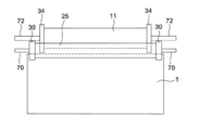
- developing roller
- developing
- sleeve
- image
- Prior art date
- Legal status (The legal status is an assumption and is not a legal conclusion. Google has not performed a legal analysis and makes no representation as to the accuracy of the status listed.)
- Ceased
Links
Images




Classifications
-
- G—PHYSICS
- G03—PHOTOGRAPHY; CINEMATOGRAPHY; ANALOGOUS TECHNIQUES USING WAVES OTHER THAN OPTICAL WAVES; ELECTROGRAPHY; HOLOGRAPHY
- G03G—ELECTROGRAPHY; ELECTROPHOTOGRAPHY; MAGNETOGRAPHY
- G03G15/00—Apparatus for electrographic processes using a charge pattern
- G03G15/06—Apparatus for electrographic processes using a charge pattern for developing
- G03G15/08—Apparatus for electrographic processes using a charge pattern for developing using a solid developer, e.g. powder developer
- G03G15/0896—Arrangements or disposition of the complete developer unit or parts thereof not provided for by groups G03G15/08 - G03G15/0894
-
- G—PHYSICS
- G03—PHOTOGRAPHY; CINEMATOGRAPHY; ANALOGOUS TECHNIQUES USING WAVES OTHER THAN OPTICAL WAVES; ELECTROGRAPHY; HOLOGRAPHY
- G03G—ELECTROGRAPHY; ELECTROPHOTOGRAPHY; MAGNETOGRAPHY
- G03G15/00—Apparatus for electrographic processes using a charge pattern
- G03G15/06—Apparatus for electrographic processes using a charge pattern for developing
- G03G15/08—Apparatus for electrographic processes using a charge pattern for developing using a solid developer, e.g. powder developer
- G03G15/0806—Apparatus for electrographic processes using a charge pattern for developing using a solid developer, e.g. powder developer on a donor element, e.g. belt, roller
- G03G15/0818—Apparatus for electrographic processes using a charge pattern for developing using a solid developer, e.g. powder developer on a donor element, e.g. belt, roller characterised by the structure of the donor member, e.g. surface properties
-
- G—PHYSICS
- G03—PHOTOGRAPHY; CINEMATOGRAPHY; ANALOGOUS TECHNIQUES USING WAVES OTHER THAN OPTICAL WAVES; ELECTROGRAPHY; HOLOGRAPHY
- G03G—ELECTROGRAPHY; ELECTROPHOTOGRAPHY; MAGNETOGRAPHY
- G03G2215/00—Apparatus for electrophotographic processes
- G03G2215/06—Developing structures, details
- G03G2215/0634—Developing device
- G03G2215/0636—Specific type of dry developer device
- G03G2215/0648—Two or more donor members
Definitions
- the present invention relates to an image forming apparatus.
- the one-component development system is advantageous in terms of simplification, miniaturization, and cost reduction of the apparatus, but the deterioration of the toner is likely to be accelerated by the strong stress of the regulating part that charges the toner, and the charge acceptability of the toner is reduced. It's easy to do. Furthermore, the toner regulating member and the surface of the developing roller are contaminated with the toner and the external additive, so that the charge imparting property to the toner is also lowered, and as a result, the life of the developing device is shortened.
- the toner is charged by frictional charging by mixing with the carrier, so that the stress is small and it is advantageous for the deterioration of the toner. Furthermore, since the carrier surface area is large, it is relatively resistant to contamination by toner and external additives, which is advantageous for extending the service life.
- a two-component developer is carried on a sleeve roller and only toner is supplied from the two-component developer to the development roller.
- a so-called hybrid development system used for development is disclosed (see Patent Document 1).
- the rotating shaft holding body having a pair of holding openings for rotatably holding the rotating shafts of the magnetic roller and the developing roller is integrally provided, and the developing roller side is provided.
- An image forming apparatus is disclosed in which the opening is configured to be swingable about the axis of the magnetic roller (see Patent Document 2).
- the developing roller and the magnetic roller are provided with respective gears, the driving force is transmitted from the magnetic roller to the developing roller via the idle gear, and the rotating shaft holder swings around the axis of the developing roller and the magnetic roller.
- An image forming apparatus is disclosed in which a magnetic roller, a developing roller, and an image carrier are uniformly spaced by holding an idle gear (see Patent Document 3).
- the magnetic roller, the developing roller, and the gap pulley are rotatably supported, and a movable bearing for supporting the developer regulating plate is provided, and the movable bearing is urged toward the image bearing member so that the magnetic roller, the developing roller, and the image are supported.
- An image forming apparatus is disclosed in which the carriers are uniformly spaced (see Patent Document 4).
- the image carrier and the two developing rollers A structure is required in which the gaps between the two are stably spaced uniformly in the axial direction.
- Patent Document 5 a developing device having a plurality of developing rollers is made detachable from the image forming apparatus main body, and the gap between the image carrier and the two developing rollers is stably and uniformly in the axial direction. There is no disclosure of a configuration with a short interval.
- the developing apparatus is configured to be detachable in the case where there is one developing roller, and the magnetic roller, the developing roller, and the image carrier are respectively spaced uniformly.
- it is not applicable to a developing device having two developing rollers.
- the present invention has been made in view of the above problems, and with a simple configuration, the gap between the image carrier and the two developing rollers is kept at a predetermined interval to suppress image defects and obtain a high-quality image.
- An object of the present invention is to provide an image forming apparatus.
- the present invention has the following characteristics.
- An image carrier A first developing roller and a second developing roller that develop an electrostatic latent image on the image carrier using a thin toner layer formed on the surface, and convey the developer while holding the developer on the outer periphery.
- a magnet roller having a magnet body fixedly arranged and a rotatable sleeve roller containing the magnet body in order to supply toner to the first developing roller and the second developing roller arranged at a position;
- a developing device comprising: An image forming apparatus having A first spacing member disposed on both ends of the first developing roller on the same axis as the first developing roller, and having an outer diameter larger than that of the first developing roller;
- a second spacing member disposed on both ends of the second developing roller on the same axis as the second developing roller and having an outer diameter larger than that of the second developing roller;
- a pair of first holding members that integrally hold the rotation shafts of the sleeve roller and the first developing roller at predetermined intervals so as to be rotatable;
- a pair of second holding members
- the developing device housing of the developing device is The first spacing member is configured to be movable in a direction in contact with the image carrier, 2.
- the first developing roller is 3.
- the first developing roller is 4.
- the first developing roller is 5.
- the sleeve roller has a pair of third spacing members arranged on the same axis as the sleeve roller at positions where both ends of the sleeve roller can come into contact with the first developing roller and having an outer diameter larger than that of the sleeve roller.
- the first holding member is 6.
- the sleeve roller has a pair of third spacing members arranged on the same axis as the sleeve roller at positions where both ends of the sleeve roller can come into contact with the second developing roller and having an outer diameter larger than that of the sleeve roller.
- the second holding member is 7.
- the first developing roller has a first spacing member having an outer diameter larger than that of the first developing roller
- the second developing roller has a second spacing member having a larger outer diameter than that of the second developing roller.
- the first spacing member and the second spacing member are urged so as to contact the image carrier.
- FIG. 1 is a cross-sectional view illustrating a configuration example of a main part of a developing device 2 and an image forming apparatus including the developing device 2 according to an embodiment of the present invention.
- 3 is an enlarged cross-sectional view of some of main components of the developing device 2.
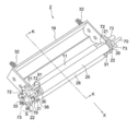
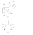
- FIG. 1 is an external view of a developing device 2 according to a first embodiment. It is a top view of the 1st holding member 21 and the 2nd holding member 22 of a 1st embodiment.
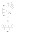
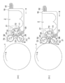
- FIG. 6 is an explanatory diagram illustrating an operation when the developing device 2 of the first embodiment is attached to the image forming apparatus. It is an external view of the developing device 2 of the second embodiment. It is a top view of the 1st holding member 21 and the 2nd holding member 22 of a 2nd embodiment. It is explanatory drawing explaining operation
- 3 is a plan view for explaining the positional relationship among the Mag roller 11, the first developing roller
- FIG. 1 shows a configuration example of a main part of an image forming apparatus according to an embodiment of the present invention. The schematic configuration and operation of the image forming apparatus will be described with reference to FIG.
- This image forming apparatus is a printer that forms an image by transferring a toner image formed on an image carrier (photosensitive member) 1 to a transfer medium P such as paper by an electrophotographic method.
- the image forming apparatus includes an image carrier 1 for carrying an image.
- a charging member 3 for charging the image carrier 1 and an image carrier 1 are provided.
- a developing device 2 for developing an electrostatic latent image, a transfer roller 4 for transferring a toner image on the image carrier 1, and a cleaning blade 5 for removing residual toner on the image carrier 1 are provided on the image carrier 1. They are arranged in order along the rotation direction A.
- the image carrier 1 is charged by the charging member 3 and then exposed by an exposure device 6 equipped with a laser emitter and the like, and an electrostatic latent image is formed on the surface thereof.
- the developing device 2 develops the electrostatic latent image to form a toner image.
- the transfer roller 4 transfers the toner image on the image carrier 1 to the transfer medium P, and then discharges it in the direction of arrow C in the figure.
- the cleaning blade 5 removes the residual toner on the image carrier 1 after the transfer with a mechanical force.
- the charging member 3, the exposure device 6, the transfer roller 4, the cleaning blade 5 and the like used in the image forming apparatus a well-known electrophotographic technique may be arbitrarily used.
- a charging roller is shown as the charging member 3 in the figure, a charging device that is not in contact with the image carrier 1 may be used.
- the cleaning blade 5 may not be provided.
- the developing device housing 19 of the developing device 2 is configured to be movable in the arrow X direction or the reverse direction along a guide (not shown) provided on the image forming apparatus main body side, and is detachable.
- One end of the first urging member 32 is fixed to the image forming apparatus main body side, and the other end urges the developing device housing 19 in the direction of the arrow X, and the first spacing member will be described in detail later. 30 is brought into contact with the image carrier 1.
- a compression coil spring or a tension coil spring for the first urging member 32, it is not particularly limited, and a torsion spring, a thin plate spring, or an elastic rubber is used. Also good.
- the main components of the developing device 2 are a developer tank 16, a Mag roller 11, a first developing roller 25, and a second developing roller 26.
- FIG. 2 is an enlarged cross-sectional view of some of the main components of the developing device 2 shown in FIG. 1
- FIG. 3 is an external view of the developing device 2 of the first embodiment
- FIG. 4 is the first embodiment.
- FIG. 5 is an explanatory diagram for explaining the operation when the developing device 2 of the first embodiment is attached to the image forming apparatus. 1 and FIG. 5 is a cross section of a portion indicated by an arrow KK in FIG.
- the developer tank 16 contains a developer 24 including a toner 23 and a carrier.
- the developing device housing 19 is provided with a replenishing unit 14 for replenishing the developer tank 16 with the toner 23 consumed in the first developing area 8 and the second developing area 12.
- the toner 23 is sent from a hopper (not shown) containing the toner 23 and supplied from the supply unit 14 into the developer tank 16.
- the supply of the toner 23 is controlled based on the output of the ATDC sensor 20 (Automatic Toner Density Control) for detecting the toner concentration.
- mixing stirring members 17 and 18 are provided in the inside of the developing device housing 19.
- the mixing and agitating members 17 and 18 mix and agitate the developer 24 to frictionally charge it, and supply the developer 24 to the Mag roller 11.
- the Mag roller 11 includes a magnet body 28 that is fixedly arranged and a rotatable sleeve roller 29 that contains the magnet body 28. During image formation, the Mag roller 11 applies toner 23 to the first developing roller 25 and the second developing roller 26. A toner supply bias voltage for supply is applied by the Mag roller bias power supply 82.
- the sleeve roller 29 is connected to the rotation shaft 72 of the Mag roller 11. When the rotation shaft 72 is rotated by a motor (not shown), the sleeve roller 29 is connected to rotate.
- the Mag roller 11 is a magnet roller of the present invention.
- the developer 24 supplied to the Mag roller 11 is held on the surface side of the sleeve roller 29 by the magnetic force of the magnet body 28 and rotates in the direction of arrow B together with the sleeve roller 29.
- the regulating member 15 is arranged at a position facing the sleeve roller 29 and regulates the developer 24 held on the surface side of the sleeve roller 29 to a predetermined amount.
- the magnet body 28 has seven magnetic poles S3, N1, S1, N2, N3, S2, and N4 along the rotation direction of the sleeve roller 29 as shown in FIG. Of these magnetic poles, N4 is the position of the first toner supply area E facing the first developing roller 25, and N1 is the position of the second toner supply area G facing the second developing roller 26. Is arranged.
- N2 and N3 are arranged on the side of the mixing and agitating member 17 in order to generate a repulsive magnetic field for peeling off the developer 24 on the sleeve roller 29.
- the first developing roller 25 is disposed on the upstream side in the transport direction of the developer 24, and the second developing roller 25 is disposed on the downstream side.
- the first developing roller 25 and the second developing roller 25 hold and convey the toner 23 on the outer periphery, respectively, and develop the electrostatic latent image formed on the image carrier 1 by flying the toner 23. To do.
- the developing roller bias power supply 81 supplies a developing bias voltage to the first developing roller 25 and the second developing roller 26.
- the Mag roller bias power supply 82 supplies a toner supply bias voltage to the sleeve roller 29 of the Mag roller 11.
- a two-component developer composed of toner 23 and a carrier is used, and the toner 23 is charged with a negative polarity and the carrier is charged with a positive polarity by frictional contact with each other. It shall be. Further, the outer peripheral surface of the image carrier 1 is negatively charged (for example, ⁇ 500 V), and toner is attached to a portion where the potential is attenuated by exposure (for example, ⁇ 50 V), and development is performed.
- the developing bias voltage is set to -300V
- the toner supply bias voltage is set to -350 to -650V.
- the first toner supply region E between the Mag roller 11 and the first developing roller 25 is applied by applying a voltage to the first developing roller 25, the second developing roller 26, and the sleeve roller 29. Then, an electric field for attracting the negatively charged toner from the Mag roller 11 toward the first developing roller 25 is formed. In the second toner supply region G between the Mag roller 11 and the second developing roller 26, an electric field that attracts the toner 23 from the Mag roller 11 toward the second developing roller 26 is formed.
- the first developing roller 25 and the second developing roller 26 may be made of any material as long as the voltage can be applied, and examples thereof include an aluminum roller that has been subjected to a surface treatment such as alumite.
- rubber such as polyester resin, polycarbonate resin, acrylic resin, polyethylene resin, polypropylene resin, urethane resin, polyamide resin, polyimide resin, polysulfone resin, polyetherketone resin, vinyl chloride resin, etc. on a conductive substrate such as aluminum You may use what gave the coating.
- resin coatings such as a vinyl acetate resin, a silicone resin, a fluororesin, and rubber coatings, such as silicone rubber, urethane rubber, nitrile rubber, natural rubber, and isoprene rubber.
- the coating material is not limited to these.
- a conductive agent may be added to the bulk or surface of the coating.
- the conductive agent include an electronic conductive agent or an ionic conductive agent.
- the electronic conductive agent include carbon black such as kettin black, acetylene black, and furnace black, metal powder, and metal oxide fine particles, but are not limited thereto.
- the ionic conductive agent include cationic compounds such as quaternary ammonium salts, amphoteric compounds, and other ionic polymer materials, but they are not particularly limited.
- a conductive roller made of a metal material such as aluminum may be used.
- the first spacing member 30 has a ring shape and is arranged at both ends of the first developing roller 25 so as to slide and rotate with the rotation shaft 70 of the first developing roller 25.
- the radius of the outer periphery of the first spacing member 30 is larger than the radius of the first developing roller 25 by a predetermined gap (from 0.1 mm) necessary for the gap between the image carrier 1 and the first developing roller 25. 0.4 mm) is set to be larger.
- the second spacing member 31 has a ring shape and is arranged at both ends of the second developing roller 26 so as to slide and rotate with the rotation shaft 73 of the second developing roller 26.
- the radius of the outer periphery of the second spacing member 31 is a predetermined gap (from 0.1 mm) between the image carrier 1 and the second developing roller 26 than the radius of the second developing roller 26. 0.4 mm) is set to be larger.
- the first spacing member 30 and the second spacing member 31 are preferably formed of a low friction member.
- Teflon registered trademark
- a metal material with a coating such as) may be used.
- a commercially available ball bearing may be incorporated in the bearing portion.
- the developing device casing 19 is provided with bearing portions (not shown) that rotatably hold the rotation shaft of the Mag roller 11 on both sides, and the rotation shaft 72 of the Mag roller 11 after assembly is held by the bearing portion and is developed. Projecting from the housing 19.
- the first holding member 21 is a bearing that integrally holds a rotary shaft 72 of the Mag roller 11 and a rotary shaft 70 of the first developing roller 25 at a predetermined interval so as to be rotatable.
- a portion 90 and a bearing portion 91 are provided.
- the rotating shaft 72 protruding from the developing device housing 19 is held by the bearing portion 90 of the first holding member 21.
- the rotation shaft 70 of the first developing roller 25 is held by the bearing portion 91 of the first holding member 21.
- the distance between the bearing portion 90 and the bearing portion 91 is set so that the gap from the surface of the Mag roller 11 to the surface of the first developing roller 25 becomes a predetermined value (0.2 mm to 1.0 mm). .
- the first holding member 21 is positioned by a positioning unit (not shown) so that the main magnetic pole N4 of the magnet body 28 fixed to the developing device casing 19 and the first developing roller 25 face each other. 19 is fixed.
- the holes 93 and 93 are holes for screwing the developing device housing 19. Note that the first holding member 21 may be integrally formed with the developing device housing 19.
- the first holding member 21 maintains the gap between the surface of the first developing roller 25 and the surface of the sleeve roller 29 of the Mag roller 11 with high accuracy, and the first developing roller 25 is connected to the main magnetic pole N4 of the magnet body 28. Can be accurately maintained at a position opposite to.
- the second holding member 22 is a bearing portion that integrally holds the rotary shaft 73 of the second developing roller 26 and the rotary shaft 72 of the Mag roller 11 so as to be rotatable at a predetermined interval. 95 and a bearing portion 96.
- the rotating shaft 72 protruding from the developing device housing 19 is held by the bearing portion 96 of the second holding member 22.
- the distance between the bearing portion 95 and the bearing portion 96 of the second holding member 22 is such that the clearance from the surface of the sleeve roller 29 of the Mag roller 11 to the surface of the second developing roller 26 is a predetermined value (0.2 mm to 1.0 mm). It is set to be.
- One end of the second urging member 33 is fixed to the developing device housing 19, and the other end is arranged such that a spacing member 31 provided at both ends of the second developing roller 26 contacts the image carrier 1.
- the second holding member 22 is urged in the arrow S direction.
- the second urging member 33 it is desirable to use a compression coil spring or a tension coil spring, but it is not particularly limited, and a torsion spring, a thin plate spring, or an elastic rubber is used. Also good.
- the rotating shaft 72, the rotating shaft 70, and the rotating shaft 73 are connected by a gear (not shown), and the first developing roller 25 and the second developing roller 26 are rotated by rotating the rotating shaft 72 by a motor (not shown). Are configured to rotate in conjunction with each other.
- FIG. 5A shows a state before the developing device 2 is attached to the image forming apparatus
- FIG. 5B shows a state where the developing device 2 is attached to the image forming apparatus.
- the developing device casing 19 is urged in the direction of the arrow X by the first urging member 32, so that it moves as shown in FIG. 5B and is provided at both ends of the first developing roller 25.
- the first spacing member 30 thus brought into contact with the surface of the image carrier 1.
- a gap corresponding to the difference between the radius of the first spacing member 30 and the radius of the first developing roller 25 is formed between the surface of the image carrier 1 and the surface of the first developing roller 25.
- the second holding member 22 is urged in the direction of arrow S by the second urging member 33, as shown in FIG. 5B, the second holding member 22 is provided at both ends of the second developing roller 26.
- Two spacing members 31 abut on the surface of the image carrier 1 that is rotatably fixed to the image forming apparatus.
- a gap corresponding to the difference between the radius of the second spacing member 31 and the radius of the second developing roller 26 is formed between the surface of the image carrier 1 and the surface of the second developing roller 26.
- the developer 24 in the developer tank 16 is mixed and stirred by the rotation of the mixing and stirring members 17 and 18 and is frictionally charged. At the same time, it is circulated and conveyed in the developer tank and supplied to the sleeve roller 29 on the surface of the Mag roller 11. .
- the developer 24 is held on the surface side of the sleeve roller 29 by the magnetic force of the magnet body 28 inside the toner supply Mag roller 11, rotates with the sleeve roller 29, and is provided so as to face the developing roller 11.
- the passage amount is regulated by the member 15.
- the developer 24 that passes through the regulating member 15 and is held on the surface side of the sleeve roller 29 is conveyed to the first toner supply region E facing the first developing roller 25 as the sleeve roller 29 rotates. Is done.
- developer spikes are formed by the magnetic force of the main magnetic pole N 4 of the magnet body 28, and the development bias voltage applied to the first development roller 25 and the toner supply applied to the Mag roller 11.
- the toner 23 in the developer 24 is supplied to the first developing roller 25 side by the force applied to the toner 23 by the electric field formed by the bias voltage.
- the toner 23 supplied to the first developing roller 25 is conveyed to the first developing area 8 as the first developing roller 25 rotates, and is formed by the developing bias voltage and the latent image potential on the image carrier.
- the electrostatic latent image is developed into a visible image by the applied electric field.
- the development method may be a reversal development method or a regular development method.
- the toner 23 on the surface of the first developing roller 25 that has consumed toner in the first developing area 8 is conveyed to the first collecting area F as the first developing roller 25 rotates.
- undeveloped toner 23 remaining on the first development roller 25 is collected from the first development roller 25 to the Mag roller 11.
- the undeveloped toner 23 includes an electrostatic force generated by an electric field formed by a voltage applied to the first developing roller 25 and a voltage applied to the Mag roller 11 and a counter charge of the developer, and Mag.
- the roller 11 is moved from the first developing roller 25 to the surface of the sleeve roller 29 by a mechanical rubbing force caused by the developer spiked by the magnetic force of the main magnetic pole N4 of the roller 11.
- the developer 24 containing the toner 23 collected on the surface of the sleeve roller 29 is conveyed to the second toner supply region G facing the second developing roller 26 as the sleeve roller 29 rotates.
- developer spikes are formed by the magnetic force of the main magnetic pole N 1 of the magnet body 28, and the development bias voltage applied to the second development roller 26 and the toner supply bias applied to the Mag roller 11.
- the toner in the developer is supplied to the second developing roller 26 side by the force applied to the toner by the electric field formed by the voltage.
- the toner layer supplied to the second developing roller 26 is transported to the second developing region 12 as the second developing roller 26 rotates, and the second development is performed.
- the toner layer on the surface of the second developing roller 26 that has consumed toner in the second developing area 12 is conveyed to the second collecting area H and collected from the second developing roller 26 to the Mag roller 11.
- the collected developer 24 rotates and moves together with the sleeve roller 29 of the Mag roller 11 and is conveyed toward the developer tank 16, and is peeled off from the Mag roller 11 by the repulsive magnetic fields of the same pole portions N ⁇ b> 2 and N ⁇ b> 3 of the magnet body 28. Then, it is collected into the developer tank 16.
- a supply control unit (not shown) provided in the supply unit 14 detects from the output value of the ATDC sensor 20 that the toner concentration in the developer 24 has become equal to or lower than the minimum toner concentration for ensuring image density, it is not shown.
- the toner 23 stored in the hopper is supplied into the developer tank 16 through the toner supply unit 14 by the toner supply means.
- the Mag roller 11 supplies the toner 23 to the first developing roller 25 arranged on the upstream side in the direction in which the developer 24 is conveyed, and then the development residual on the first developing roller 25.
- the toner is collected in the developer 24 on the Mag roller 11, and the toner 23 is supplied to the second developing roller 26 disposed on the downstream side. Therefore, the first developing roller 25 has a larger amount of toner on the roller surface, and the load for supplying and collecting the toner 23 becomes higher.
- the rotation shaft 70 of the first developing roller 25 is held by the first holding member 21 fixed to the developing device housing 19, and the main magnetic pole N ⁇ b> 4 of the magnet body 28 is accurately positioned at the position where it faces. Therefore, all the development residual toner on the first developing roller 25 can be collected and the development history (ghost) can be eliminated.
- the first developing roller 25 is arranged on the upstream side in the moving direction (arrow A direction) of the image carrier 1, the toner can be sufficiently supplied to the image carrier 1.
- the upstream developing roller requires more toner on the roller surface, but the conditions such as the voltage applied to the developing roller, the surface resistance value of the developing roller surface, and the number of rotations of the developing roller are upstream.
- the amount of toner on the roller surface of the developing roller on the downstream side can be increased by changing between the side and the downstream side.
- the upstream first developing roller 25 since the upstream first developing roller 25 has a larger amount of toner on the roller surface, the first developing roller 25 is fixed by the first holding member 21 fixed to the developing device casing 19. keeping.
- the downstream developing roller when the downstream developing roller has a larger amount of toner on the roller surface, the downstream developing roller is held by a holding member fixed to the developing device housing 19, and the upstream developing roller is rotated. What is necessary is just to hold
- FIG. 6 is an external view of the developing device 2 of the second embodiment
- FIG. 7 is a plan view of the first holding member 21b and the second holding member 22b of the second embodiment
- the cross section of the developing device 2 shown in FIG. 8 is a cross section of a portion indicated by an arrow KK in FIG.
- the difference between the developing device 2 according to the second embodiment and the developing device 2 according to the first embodiment is that the third spacing member 34 is provided at both ends of the Mag roller 11 and the rotating shaft 70 and the rotating shaft 73 are connected to the Mag.
- the roller 11 is configured to be held so as to be movable in the normal direction of the roller 11.
- the third spacing member 34 has a ring shape and is arranged at both ends of the Mag roller 11 so as to slide and rotate with the first developing roller 25.
- the radius of the outer periphery of the third spacing member 34 is less than the radius of the first developing roller 25 by a predetermined gap (from 0.2 mm to 1 mm) necessary for the gap between the Mag roller 11 and the first developing roller 25. 0.0 mm) is set to be larger.
- the gap between the Mag roller 11 and the second developing roller 26 is the same as the gap between the Mag roller 11 and the first developing roller 25, and the third spacing member 34 serves as the second developing member.
- the roller 26 is also arranged to slide and rotate.
- the 3rd spacing member 34 it is desirable to form an outer peripheral surface with a low friction member like the 1st spacing member 30 and the 2nd spacing member 31.
- a low friction member Teflon (registered trademark) is integrally formed of a resin material having a low coefficient of friction such as polyacetal, or an outer peripheral surface on which the image carrier 1 slides and a bearing portion on which the rotary shaft 70 and the rotary shaft 73 slide.
- a metal material with a coating such as) may be used.
- a commercially available ball bearing may be incorporated in the bearing portion.
- the first holding member 21 b has a shape of a bearing portion 97 that holds the rotation shaft 70 of the first developing roller 25, and the rotation shaft 70 moves in the normal direction of the Mag roller 11. It is oval so you can do it.
- the rotation shaft 70 of the first developing roller 25 moves in the arrow J direction or the reverse direction along the bearing portion 97. It is configured to be possible.
- An arrow J direction is a normal direction of the Mag roller 11 and is a direction facing the main magnetic pole N4 of the magnet body 28 of the first developing roller 25.
- an urging member that urges the first developing roller 25 in a direction to contact the spacing member 34 may be provided.
- the shape of the bearing portion 98 that holds the rotating shaft 73 of the second developing roller 26 is such that the rotating shaft 73 is in the normal direction of the Mag roller 11. It is oval so that it can be moved to.
- the rotating shaft 73 of the second holding member 22 moves in the direction of arrow I or in the opposite direction along the bearing portion 98 as shown in FIG. It is configured to be possible.
- An arrow I direction is a normal line direction of the Mag roller 11 and is a direction facing the main magnetic pole N1 of the magnet body 28 of the second developing roller 26.
- the developer tank 19 is urged by the first urging member 32 and moves in the direction of the arrow X, and the second spacing member 31 urged by the second urging member 33 is applied to the image carrier 1.
- the rotating shaft 73 moves in the direction of arrow I, and the second developing roller 26 contacts the third spacing member 34.
- an urging member that urges the second developing roller 26 in a direction to contact the spacing member 34 may be provided.
- FIG. 9 is a plan view for explaining the positional relationship among the Mag roller 11, the first developing roller 25, and the image carrier 1.
- the length of the first developing roller 25 in the left-right direction in the drawing is longer than that of the Mag roller 11, and the second developing roller 26 (not shown in FIG. 9) is the same length as the first developing roller 25. That's it.
- the third spacing member 34 is attached at a position where it abuts on the first developing roller 25 and the second developing roller 26.
- the third spacing member 34 is configured to abut against the first developing roller 25 and the second developing roller 26, but the third spacing member 34 is one of the three developing members. You may comprise so that it may contact
- a third bearing member 97 having an oval bearing 97 shown in FIG.
- the gap between the image carrier and the two developing rollers is kept at a predetermined interval, and image formation in which high-quality images can be obtained while suppressing image defects.
- An apparatus can be provided.
Landscapes
- Physics & Mathematics (AREA)
- General Physics & Mathematics (AREA)
- Dry Development In Electrophotography (AREA)
Abstract
Description
表面に形成されるトナー薄層を用いて前記像担持体の静電潜像を現像する第1の現像ローラおよび第2の現像ローラと、外周部に現像剤を保持して搬送し、対向する位置に配置された前記第1の現像ローラおよび前記第2の現像ローラにトナーを供給するために、固定配置された磁石体及び当該磁石体を内包する回転可能なスリーブローラを有するマグネットローラと、を備えた現像装置と、
を有する画像形成装置であって、
前記第1の現像ローラの両端部に前記第1の現像ローラと等軸に配設され、外径が前記第1の現像ローラよりも大きい第1の間隔部材と、
前記第2の現像ローラの両端部に前記第2の現像ローラと等軸に配設され、外径が前記第2の現像ローラよりも大きい第2の間隔部材と、
前記スリーブローラおよび前記第1の現像ローラのそれぞれの回転軸を、回転可能に所定の間隔で一体的に保持する一対の第1の保持部材と、
前記第2の現像ローラの回転軸を回転可能に保持し、前記スリーブローラの回転軸に対し揺動可能に取り付けられた一対の第2の保持部材と、
前記第1の間隔部材を前記像担持体に当接するように付勢する第1の付勢部材と、
前記第2の間隔部材を前記像担持体に当接するように付勢する第2の付勢部材と、
を有することを特徴とする画像形成装置。
前記第1の間隔部材が前記像担持体に当接する方向に移動可能に構成され、
前記第1の付勢部材は、前記現像器筐体を付勢することを特徴とする1に記載の画像形成装置。
前記マグネットローラから供給されるトナー量が前記第2の現像ローラより多いことを特徴とする1または2に記載の画像形成装置。
前記マグネットローラによって搬送される前記現像剤の搬送方向の上流側に配置されていることを特徴とする3に記載の画像形成装置。
前記第2の現像ローラより前記像担持体の移動方向の上流側に配置されていることを特徴とする1から4の何れか1項に記載の画像形成装置。
前記第1の保持部材は、
前記第1の現像ローラの回転軸を前記スリーブローラの法線方向に向けて移動可能に保持するように構成されていることを特徴とする1から5の何れか1項に記載の画像形成装置。
前記第2の保持部材は、
前記第2の現像ローラの回転軸を前記スリーブローラの法線方向に向けて移動可能に保持するように構成されていることを特徴とする1から6の何れか1項に記載の画像形成装置。
図1に、本発明の一実施形態による画像形成装置の主要部の構成例を示す。図1を用いて画像形成装置の概略構成と動作を説明する。
2 現像装置
3 帯電部材
4 転写ローラ
5 クリーニングブレード
6 露光装置
11 Magローラ
12 スリーブローラ
13 磁石体
16 現像剤槽
17、18 混合撹拌部材
19 現像器筐体
20 ATDCセンサ
21、21b 第1の保持部材
22、22b 第2の保持部材
23 トナー
24 現像剤
25 第1の現像ローラ
26 第2の現像ローラ
28 磁石体
29 スリーブローラ
30 第1の間隔部材
31 第2の間隔部材
32 第1の付勢部材
33 第2の付勢部材
81 現像ローラ用バイアス電源
82 Magローラ用バイアス電源
E 第1のトナー供給領域
F 第1の回収領域
G 第2のトナー供給領域
H 第2の回収領域
Claims (7)
- 像担持体と、
表面に形成されるトナー薄層を用いて前記像担持体の静電潜像を現像する第1の現像ローラおよび第2の現像ローラと、外周部に現像剤を保持して搬送し、対向する位置に配置された前記第1の現像ローラおよび前記第2の現像ローラにトナーを供給するために、固定配置された磁石体及び当該磁石体を内包する回転可能なスリーブローラを有するマグネットローラと、を備えた現像装置と、
を有する画像形成装置であって、
前記第1の現像ローラの両端部に前記第1の現像ローラと等軸に配設され、外径が前記第1の現像ローラよりも大きい第1の間隔部材と、
前記第2の現像ローラの両端部に前記第2の現像ローラと等軸に配設され、外径が前記第2の現像ローラよりも大きい第2の間隔部材と、
前記スリーブローラおよび前記第1の現像ローラのそれぞれの回転軸を、回転可能に所定の間隔で一体的に保持する一対の第1の保持部材と、
前記第2の現像ローラの回転軸を回転可能に保持し、前記スリーブローラの回転軸に対し揺動可能に取り付けられた一対の第2の保持部材と、
前記第1の間隔部材を前記像担持体に当接するように付勢する第1の付勢部材と、
前記第2の間隔部材を前記像担持体に当接するように付勢する第2の付勢部材と、
を有することを特徴とする画像形成装置。 - 前記現像装置の現像器筐体は、
前記第1の間隔部材が前記像担持体に当接する方向に移動可能に構成され、
前記第1の付勢部材は、前記現像器筐体を付勢することを特徴とする請求項1に記載の画像形成装置。 - 前記第1の現像ローラは、
前記マグネットローラから供給されるトナー量が前記第2の現像ローラより多いことを特徴とする請求項1または2に記載の画像形成装置。 - 前記第1の現像ローラは、
前記マグネットローラによって搬送される前記現像剤の搬送方向の上流側に配置されていることを特徴とする請求項3に記載の画像形成装置。 - 前記第1の現像ローラは、
前記第2の現像ローラより前記像担持体の移動方向の上流側に配置されていることを特徴とする請求項1から4の何れか1項に記載の画像形成装置。 - 前記スリーブローラの両端部の前記第1の現像ローラと当接可能な位置に前記スリーブローラと等軸に配設され、外径が前記スリーブローラよりも大きい一対の第3の間隔部材を有し、
前記第1の保持部材は、
前記第1の現像ローラの回転軸を前記スリーブローラの法線方向に向けて移動可能に保持するように構成されていることを特徴とする請求項1から5の何れか1項に記載の画像形成装置。 - 前記スリーブローラの両端部の前記第2の現像ローラと当接可能な位置に前記スリーブローラと等軸に配設され、外径が前記スリーブローラよりも大きい一対の第3の間隔部材を有し、
前記第2の保持部材は、
前記第2の現像ローラの回転軸を前記スリーブローラの法線方向に向けて移動可能に保持するように構成されていることを特徴とする請求項1から6の何れか1項に記載の画像形成装置。
Priority Applications (2)
| Application Number | Priority Date | Filing Date | Title |
|---|---|---|---|
| JP2010540448A JP4930639B2 (ja) | 2008-11-27 | 2009-11-13 | 画像形成装置 |
| US13/130,874 US8509659B2 (en) | 2008-11-27 | 2009-11-13 | Image forming apparatus |
Applications Claiming Priority (2)
| Application Number | Priority Date | Filing Date | Title |
|---|---|---|---|
| JP2008302212 | 2008-11-27 | ||
| JP2008-302212 | 2008-11-27 |
Publications (1)
| Publication Number | Publication Date |
|---|---|
| WO2010061741A1 true WO2010061741A1 (ja) | 2010-06-03 |
Family
ID=42225619
Family Applications (1)
| Application Number | Title | Priority Date | Filing Date |
|---|---|---|---|
| PCT/JP2009/069361 Ceased WO2010061741A1 (ja) | 2008-11-27 | 2009-11-13 | 画像形成装置 |
Country Status (3)
| Country | Link |
|---|---|
| US (1) | US8509659B2 (ja) |
| JP (1) | JP4930639B2 (ja) |
| WO (1) | WO2010061741A1 (ja) |
Cited By (1)
| Publication number | Priority date | Publication date | Assignee | Title |
|---|---|---|---|---|
| JP2013222146A (ja) * | 2012-04-18 | 2013-10-28 | Konica Minolta Inc | 現像装置および画像形成装置 |
Families Citing this family (2)
| Publication number | Priority date | Publication date | Assignee | Title |
|---|---|---|---|---|
| JP5624279B2 (ja) * | 2009-04-01 | 2014-11-12 | コニカミノルタ株式会社 | 現像装置 |
| JP6919407B2 (ja) * | 2017-08-14 | 2021-08-18 | コニカミノルタ株式会社 | 現像装置および画像形成装置 |
Citations (6)
| Publication number | Priority date | Publication date | Assignee | Title |
|---|---|---|---|---|
| JP2002351211A (ja) * | 2001-05-30 | 2002-12-06 | Canon Inc | 現像装置及び画像形成装置 |
| JP2003167424A (ja) * | 2001-12-04 | 2003-06-13 | Kyocera Corp | 画像形成装置 |
| JP2003337472A (ja) * | 2002-05-20 | 2003-11-28 | Kyocera Corp | 現像装置 |
| JP2005037523A (ja) * | 2003-07-17 | 2005-02-10 | Fuji Xerox Co Ltd | 画像形成装置 |
| JP2006276853A (ja) * | 2005-03-25 | 2006-10-12 | Xerox Corp | 電子写真システム内現像システムにおけるトナーアビューズ抑制方法及びシステム |
| JP2007163766A (ja) * | 2005-12-13 | 2007-06-28 | Kyocera Mita Corp | 現像装置及びこれを備えた画像形成装置 |
Family Cites Families (5)
| Publication number | Priority date | Publication date | Assignee | Title |
|---|---|---|---|---|
| JPH05150636A (ja) | 1991-11-30 | 1993-06-18 | Toshiba Corp | 現像装置 |
| US6907216B2 (en) | 2001-12-04 | 2005-06-14 | Kyocera Corporation | Image forming apparatus having a roll supporting member |
| JP2003255694A (ja) * | 2002-02-28 | 2003-09-10 | Canon Inc | 現像装置及び画像形成装置 |
| JP2003295617A (ja) * | 2002-03-29 | 2003-10-15 | Hitachi Printing Solutions Ltd | 現像装置および静電記録装置 |
| US7660551B2 (en) * | 2007-03-15 | 2010-02-09 | Xerox Corporation | Apparatus and methods for loading a donor roll |
-
2009
- 2009-11-13 WO PCT/JP2009/069361 patent/WO2010061741A1/ja not_active Ceased
- 2009-11-13 JP JP2010540448A patent/JP4930639B2/ja not_active Expired - Fee Related
- 2009-11-13 US US13/130,874 patent/US8509659B2/en not_active Expired - Fee Related
Patent Citations (6)
| Publication number | Priority date | Publication date | Assignee | Title |
|---|---|---|---|---|
| JP2002351211A (ja) * | 2001-05-30 | 2002-12-06 | Canon Inc | 現像装置及び画像形成装置 |
| JP2003167424A (ja) * | 2001-12-04 | 2003-06-13 | Kyocera Corp | 画像形成装置 |
| JP2003337472A (ja) * | 2002-05-20 | 2003-11-28 | Kyocera Corp | 現像装置 |
| JP2005037523A (ja) * | 2003-07-17 | 2005-02-10 | Fuji Xerox Co Ltd | 画像形成装置 |
| JP2006276853A (ja) * | 2005-03-25 | 2006-10-12 | Xerox Corp | 電子写真システム内現像システムにおけるトナーアビューズ抑制方法及びシステム |
| JP2007163766A (ja) * | 2005-12-13 | 2007-06-28 | Kyocera Mita Corp | 現像装置及びこれを備えた画像形成装置 |
Cited By (1)
| Publication number | Priority date | Publication date | Assignee | Title |
|---|---|---|---|---|
| JP2013222146A (ja) * | 2012-04-18 | 2013-10-28 | Konica Minolta Inc | 現像装置および画像形成装置 |
Also Published As
| Publication number | Publication date |
|---|---|
| US8509659B2 (en) | 2013-08-13 |
| JP4930639B2 (ja) | 2012-05-16 |
| JPWO2010061741A1 (ja) | 2012-04-26 |
| US20110243615A1 (en) | 2011-10-06 |
Similar Documents
| Publication | Publication Date | Title |
|---|---|---|
| JP4642529B2 (ja) | 現像装置 | |
| US20090226220A1 (en) | Development apparatus and image forming apparatus including the same | |
| JP4930639B2 (ja) | 画像形成装置 | |
| JP5073994B2 (ja) | 現像装置、プロセスカートリッジ及び画像形成装置 | |
| JP5359766B2 (ja) | 画像形成装置 | |
| JP5029555B2 (ja) | 現像装置、及び画像形成装置 | |
| JP2011145452A (ja) | 画像形成装置 | |
| JP2013171166A (ja) | 現像装置及びこれを用いた画像形成装置 | |
| JP5115453B2 (ja) | 現像装置及び画像形成装置 | |
| JP2006259577A (ja) | 現像装置及びこれを用いた画像形成装置 | |
| JP4337533B2 (ja) | 現像装置及びこれを用いた画像形成装置 | |
| JP2007047639A (ja) | 現像装置 | |
| JP2008281739A (ja) | 現像装置及び画像形成装置 | |
| JP2010243633A (ja) | 現像装置及び画像形成装置 | |
| JP5736326B2 (ja) | 現像装置及びそれを備えた画像形成装置 | |
| JPH1144996A (ja) | 現像装置 | |
| JP2007328056A (ja) | 現像装置及びこれを用いた画像形成装置 | |
| JP5115296B2 (ja) | 現像装置、及び画像形成装置 | |
| JP5058051B2 (ja) | 現像装置及びプロセスカートリッジ | |
| JP2006184373A (ja) | 画像形成装置 | |
| JP2011141354A (ja) | 現像装置及び画像形成装置 | |
| JPH11258909A (ja) | 現像装置 | |
| JP2010128191A (ja) | 現像装置及びそれを備えた画像形成装置 | |
| JP2006317980A (ja) | 現像装置、画像形成装置及び画像形成プロセスユニット | |
| JP2011180482A (ja) | 現像装置および画像形成装置 |
Legal Events
| Date | Code | Title | Description |
|---|---|---|---|
| 121 | Ep: the epo has been informed by wipo that ep was designated in this application |
Ref document number: 09828989 Country of ref document: EP Kind code of ref document: A1 |
|
| WWE | Wipo information: entry into national phase |
Ref document number: 2010540448 Country of ref document: JP |
|
| WWE | Wipo information: entry into national phase |
Ref document number: 13130874 Country of ref document: US |
|
| NENP | Non-entry into the national phase |
Ref country code: DE |
|
| 122 | Ep: pct application non-entry in european phase |
Ref document number: 09828989 Country of ref document: EP Kind code of ref document: A1 |