WO2010052935A1 - インバータ一体型電動圧縮機 - Google Patents
インバータ一体型電動圧縮機 Download PDFInfo
- Publication number
- WO2010052935A1 WO2010052935A1 PCT/JP2009/005979 JP2009005979W WO2010052935A1 WO 2010052935 A1 WO2010052935 A1 WO 2010052935A1 JP 2009005979 W JP2009005979 W JP 2009005979W WO 2010052935 A1 WO2010052935 A1 WO 2010052935A1
- Authority
- WO
- WIPO (PCT)
- Prior art keywords
- resin
- inverter
- integrated electric
- electric compressor
- substrate
- Prior art date
- Legal status (The legal status is an assumption and is not a legal conclusion. Google has not performed a legal analysis and makes no representation as to the accuracy of the status listed.)
- Ceased
Links
Images



Classifications
-
- F—MECHANICAL ENGINEERING; LIGHTING; HEATING; WEAPONS; BLASTING
- F04—POSITIVE - DISPLACEMENT MACHINES FOR LIQUIDS; PUMPS FOR LIQUIDS OR ELASTIC FLUIDS
- F04C—ROTARY-PISTON, OR OSCILLATING-PISTON, POSITIVE-DISPLACEMENT MACHINES FOR LIQUIDS; ROTARY-PISTON, OR OSCILLATING-PISTON, POSITIVE-DISPLACEMENT PUMPS
- F04C23/00—Combinations of two or more pumps, each being of rotary-piston or oscillating-piston type, specially adapted for elastic fluids; Pumping installations specially adapted for elastic fluids; Multi-stage pumps specially adapted for elastic fluids
- F04C23/008—Hermetic pumps
-
- F—MECHANICAL ENGINEERING; LIGHTING; HEATING; WEAPONS; BLASTING
- F04—POSITIVE - DISPLACEMENT MACHINES FOR LIQUIDS; PUMPS FOR LIQUIDS OR ELASTIC FLUIDS
- F04C—ROTARY-PISTON, OR OSCILLATING-PISTON, POSITIVE-DISPLACEMENT MACHINES FOR LIQUIDS; ROTARY-PISTON, OR OSCILLATING-PISTON, POSITIVE-DISPLACEMENT PUMPS
- F04C18/00—Rotary-piston pumps specially adapted for elastic fluids
- F04C18/02—Rotary-piston pumps specially adapted for elastic fluids of arcuate-engagement type, i.e. with circular translatory movement of co-operating members, each member having the same number of teeth or tooth-equivalents
- F04C18/0207—Rotary-piston pumps specially adapted for elastic fluids of arcuate-engagement type, i.e. with circular translatory movement of co-operating members, each member having the same number of teeth or tooth-equivalents both members having co-operating elements in spiral form
- F04C18/0215—Rotary-piston pumps specially adapted for elastic fluids of arcuate-engagement type, i.e. with circular translatory movement of co-operating members, each member having the same number of teeth or tooth-equivalents both members having co-operating elements in spiral form where only one member is moving
-
- F—MECHANICAL ENGINEERING; LIGHTING; HEATING; WEAPONS; BLASTING
- F04—POSITIVE - DISPLACEMENT MACHINES FOR LIQUIDS; PUMPS FOR LIQUIDS OR ELASTIC FLUIDS
- F04C—ROTARY-PISTON, OR OSCILLATING-PISTON, POSITIVE-DISPLACEMENT MACHINES FOR LIQUIDS; ROTARY-PISTON, OR OSCILLATING-PISTON, POSITIVE-DISPLACEMENT PUMPS
- F04C2240/00—Components
- F04C2240/80—Other components
- F04C2240/808—Electronic circuits (e.g. inverters) installed inside the machine
Definitions
- the present invention relates to an inverter-integrated electric compressor, and in particular, an inverter that can realize reliable fixing of circuit components at a low cost while maintaining a high degree of design freedom, and has high vibration resistance and excellent operational stability.
- the present invention relates to an integrated electric compressor.
- Patent Document 1 As a structure of an electric compressor including a motor drive circuit including an inverter or the like, a structure in which the motor drive circuit is covered with an insulating resin mold material and embedded in the resin mold material is known (for example, Patent Document 1).
- Patent Document 2 there is also known a structure in which a power semiconductor module disposed between an upper lid and a compressor housing is covered and embedded by pouring insulating synthetic resin or the like that has been heated and flowed (for example, Patent Document 2).
- Patent Document 2 the entire chamber containing electrical components such as a power semiconductor module is filled with a resin mold material.
- JP 2002-70743 A Japanese Patent Laid-Open No. 4-80554
- the electrical components are substantially fixed only by the coating resin, it is difficult to secure a sufficient fixing force.
- the fixing force of the coating resin is reduced due to, for example, a decrease in the hardness of the coating resin in a high temperature region, and it has been difficult to wipe out the possibility that any of the desirable electrical component placement will occur.
- the thickness of the coating resin is substantially reduced to ensure a sufficient fixing force. There was a problem that it became difficult.
- the motor drive circuit and the like are substantially embedded, the amount of filling or coating resin increases, and accordingly, the weight reduction and cost reduction of the entire electric compressor are hindered.
- an electric compressor used for a vehicle air conditioner or the like it is required to reduce the weight and cost as much as possible.
- an object of the present invention is to achieve high vibration resistance by reliably fixing circuit components while maintaining a high degree of freedom in design, and is an inverter-integrated electric compression that is easy to reduce in weight and excellent in operational stability. Is to provide the machine at low cost.
- an inverter-integrated electric compressor is an inverter-integrated electric compressor having a board with a built-in motor and a motor drive circuit including the inverter,
- the electric component including the electric component is fixed in the accommodating space surrounded by the compressor housing, and after the assembly is completed, the accommodating space is filled with an insulating resin, and at least a part of the electric component is sealed with the solidified filling resin
- a concave holding portion having a concave portion formed in a concave shape along the outer shape of the circuit component provided on the substrate, and a vent hole provided in the concave holding portion.
- a resin frame is mounted on the substrate, and a resin sealing space capable of being filled with resin is formed between a circuit component on the substrate and the resin frame. Consisting of.
- the resin filling into the resin sealing space formed around the circuit component on the substrate prevents the vibration of the circuit component and covers the outer periphery of the resin sealing space. Since the resin frame is mounted on the substrate, the resin filled in the resin sealing space and solidified resin and the circuit components covered with the resin are securely fixed by the resin frame, and vibration is effectively prevented. .
- the thickness of the resin sealing space formed in the resin frame is compared with the case where the circuit component is substantially embedded and covered with only a single resin without using the resin frame in the prior art. Because it can be made very thin, it can minimize the effects of changes in the physical properties of the resin material (for example, a decrease in the hardness of the coating resin in the high temperature range).
- the members made of resin are excellent in workability and can be easily molded into various shapes, it is possible to easily manufacture a resin frame corresponding to the external shape of existing circuit components at a low cost.
- the degree of freedom in designing the compressor can be maintained at a high level that is almost the same as when a conventional resin frame is not installed. Furthermore, even when circuit components such as capacitors are enlarged, it is easy to cope with them, and it is possible to secure a sufficient fixing force for the circuit components.
- the air holes provided in the resin frame prevent the generation and remaining of bubbles in the resin when the resin filling space is filled with the resin, thereby securing the circuit components more reliably.
- the weight of the compressor can be reduced by using a resin having a density lower than that of the insulating resin as the material of the resin frame.
- the resin frame is excellent in workability.
- the weight of the compressor is further reduced. It is also possible to do it easily.
- the above-mentioned recess is not particularly limited, but is preferably formed substantially corresponding to the outer shape of each circuit component on the substrate. If the thickness of the resin layer filled around the circuit component is non-uniform, non-uniform force is applied to the circuit component due to changes in the physical properties of the resin layer (for example, changes in hardness and expansion coefficient due to temperature rise). May cause an unexpected minute shift in the arrangement of circuit components. On the other hand, when the recesses are formed to correspond to the outer shape of each circuit component, the thickness of the resin layer becomes almost uniform, so the above-described deviation is minimized, and the fixing force of the circuit component by the resin layer is high. It is stably maintained even in the region.
- the concave portion has a tapered portion around the vent hole that reduces the resin sealing space as it approaches the vent hole.
- the tapered recess is formed on the inner surface around the vent hole, the cross-sectional area of the resin sealing space near the vent hole becomes narrower as it approaches the vent hole.
- a gas such as air is easily guided to the vent hole, and a structure in which bubbles do not easily remain in the resin can be realized.
- the air holes are formed in the upper and lower surfaces of the recesses, the bubbles existing in the resin can be lifted to the outside of the resin by buoyancy, so that the remaining of the bubbles in the resin can be more effectively prevented. is there.
- the tapered portion may not be formed for all the recessed portions, but the tapered portion may be formed only for the recessed portions formed corresponding to the outer shape of the aluminum electrolytic capacitor, for example. Efficient processing to prevent residual bubbles by forming the taper part only for circuit components that tend to have air bubbles remaining in the recesses, such as aluminum electrolytic capacitors, because the installation height on the substrate is relatively large. Can be performed.
- the type of resin filled in the resin sealing space is not particularly limited, and may be the same as the insulating resin filled in the housing space, or a different type of resin may be used.
- the insulating resin is filled in the resin enclosing space by filling the housing space with the insulating resin. It is preferable to be performed together.
- the type of resin filled in the resin sealing space is not particularly limited, but is preferably an adhesive resin (for example, an adhesive). It is particularly preferable that the adhesive resin has an insulating property that can protect circuit components on the substrate from defects such as short circuits due to defects.
- the adhesive resin means a resin whose hardness is moderately lowered in a high temperature region as compared with the insulating resin filled in the accommodation space. Since such a resin has a small change in hardness, the fixing force of the circuit components at a high temperature is maintained at a higher level than that of the insulating resin, and the operational stability of the compressor can be improved.
- the filling of the adhesive resin into the resin sealing space is preferably performed before the insulating resin is filled into the housing space.
- the resin frame is preferably provided with a positioning hole for the adhesive resin injection device.
- the positioning hole need only be configured so that the adhesive resin injection device can be quickly installed at a predetermined position, and does not necessarily have to penetrate the resin frame.
- the positioning hole may be at least one concave recess formed on the surface of the resin frame in accordance with the shape of the contact portion of the adhesive resin injecting device to the resin frame. Such positioning holes facilitate the filling of the adhesive resin and reduce the time required for the compressor manufacturing process.
- the resin frame is not particularly limited, it is preferable that a resin injection hole is provided.
- a resin injection hole is provided in each of the plurality of recesses. With such a resin injection hole, it becomes easy to fill the resin filling space with no gap, and the fixing of the circuit components can be achieved more reliably.
- the resin injection hole may be the same hole as the vent hole described above or a different hole.
- the resin frame according to the present invention is not particularly limited, but is preferably mounted on the substrate in a state of being fixed to the substrate by fastening.
- the resin frame is fastened to the substrate, it is possible to prevent the resin frame from being displaced from a predetermined position when the resin is filled in the resin-filling space or the housing space, and the resin resulting from such a displacement. Generation of bubbles and filling leakage are prevented, and fixing of circuit components is reliably achieved.
- the application of the inverter-integrated electric compressor according to the present invention is not particularly limited, but high vibration resistance is required because it is possible to reliably fix circuit components at low cost while maintaining a high degree of freedom in design.
- the compressor is suitable for use in a vehicle-mounted compressor having a strict requirement for installation space, and particularly suitable for use as a compressor for a vehicle air conditioner.
- inverter-integrated electric compressor while maintaining a high degree of freedom in design, high vibration resistance can be realized by surely fixing circuit components, and weight reduction is easy.
- An inverter-integrated electric compressor with excellent operational stability can be realized at low cost.
- FIG. 1 is a schematic longitudinal sectional view of an inverter-integrated electric compressor according to an embodiment of the present invention.
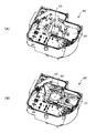
- FIG. 2A is a schematic perspective view of a housing space forming portion in the inverter-integrated electric compressor shown in FIG. 1, FIG. 2A shows a state before the resin frame is mounted, and FIG. 2B shows a state after the resin frame is mounted. Each state is shown.
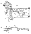
- substrate and resin frame in the inverter integrated electric compressor shown in FIG. 1 are shown, FIG. 3 (A) has shown the top view, FIG.3 (B) has shown the side view, respectively.
- FIG. 4 shows an enlarged cross-sectional view of the vicinity of the recess in the inverter-integrated electric compressor shown in FIG. 1, FIG.
- FIG. 4 (A) shows an example in which the resin sealing space is filled with insulating resin
- FIG. An example in which the resin sealing space is filled with an adhesive resin is shown.
- FIG. 5A shows a modification of the resin frame shown in FIG. 3
- FIG. 5A shows a plan view
- FIG. 5B shows a partial cross-sectional view. It is an expanded sectional view of the recessed part vicinity in the modification of the resin frame shown in FIG.
- FIG. 1 shows an inverter-integrated electric compressor according to an embodiment of the present invention, and particularly shows an example in which the present invention is applied to a scroll-type electric compressor.
- the inverter-integrated electric compressor 1 includes a compression mechanism 2 including a fixed scroll 3 and a movable scroll 4.
- the movable scroll 4 is turned with respect to the fixed scroll 3 in a state in which the rotation is prevented via the ball coupling 5.
- a motor 7 is incorporated in the compressor housing (center housing) 6, and the main shaft 8 (rotary shaft) is rotationally driven by the built-in motor 7.
- the rotational motion of the main shaft 8 is converted into the turning motion of the movable scroll 4 through the eccentric pin 9 disposed on one end side of the main shaft 8 and the eccentric bush 10 rotatably engaged thereto. ing.
- a suction port 11 for sucking refrigerant as a fluid to be compressed is provided in the compressor housing (front housing) 12, and the sucked refrigerant is guided to the compression mechanism 2 through the motor 7 arrangement portion.
- the refrigerant compressed by the compression mechanism 2 is sent to the external circuit through the discharge port 13, the discharge chamber 14, and the discharge port 16 provided in the compressor housing (rear housing) 15.
- a housing space 20 is formed by being surrounded by the extending portion of the compressor housing 12 (front housing), and a motor drive circuit 21 is provided in the housing space 20. More specifically, the motor drive circuit 21 is provided in the housing space 20 on the outer surface side of the partition wall 22 with the refrigerant suction path side formed in the compressor housing 12. The motor drive circuit 21 feeds power to the motor 7 via a sealed terminal 23 (an output terminal of the motor drive circuit 21) attached through the partition wall 22 and a lead wire 24. The path side and the motor drive circuit 21 installation side are sealed. In the present embodiment, the motor drive circuit 21 is provided on the outer surface side of the partition wall 22 so that at least a part of the electrical components including the motor drive circuit 21 can exchange heat with the suction refrigerant via the partition wall 22.
- the motor drive circuit 21 includes an IPM (Intelligent Power Module) 25 having an inverter function and a substrate 26 having a control circuit made up of circuit components 30. Separately or integrally therewith, electrical components such as a capacitor 27. Is provided.
- the motor drive circuit 21 is connected to an external power source (not shown) via a connector 28 as an input terminal.
- the opening side to the outside of the compressor housing 12 on which the electric parts including the motor drive circuit 21 are mounted is covered in a state of being sealed with a lid member 29, and these electric parts are protected by the lid member 29. .
- the substrate 26 provided with the control circuit has a resin frame having a concave holding portion 32 having a concave portion formed in a concave shape along the outer shape of the circuit component, and a vent hole 33 provided in the concave holding portion 32.
- a resin sealing space 34 that can be filled with resin is formed between the circuit component 30 provided on the substrate 26 and the resin frame 31. The resin filling into the resin sealing space 34 prevents the circuit component 26 from vibrating, and the air holes 33 prevent air bubbles from occurring and remaining in the resin, so that the fixing of the circuit component 26 is reliably achieved. Further, the resin and circuit component 26 filled and solidified in the resin sealing space 34 are securely fixed by the resin frame 31 mounted on the substrate 26.
- the insulating resin 35 is filled, and substantially all of these are solidified. Sealed with insulating resin 35. As shown in the figure, the insulating resin filling range is accommodated within the minimum necessary range in the accommodation space 20, and the overall weight of the compressor 1 is reduced. Further, as described above, it is possible to achieve further weight reduction by using a material having a lighter density than the insulating resin 35 as the material of the resin frame 31.
- FIG. 2 is a schematic perspective view of the accommodation space 20 in the inverter-integrated electric compressor shown in FIG. 1, and FIG. 2 (A) shows a state where the resin frame 31 is not attached. Indicates the state in which the resin frame 31 is mounted.
- a substrate 26 provided with a control circuit made up of circuit components 30 and a noise filter 36 are arranged in the accommodation space 20. 2 is connected to an external power source via a noise filter 36 and is protected from signal line conductive noise caused by the external power source.
- FIG. 2B shows a concave holding portion 32 provided with a concave portion formed in a concave shape along the outer shape of the circuit component 30 in the substrate 26 of FIG. 2A, and a vent hole provided in the concave holding portion 32.
- 33 shows a state in which a resin frame 31 having 33 is mounted. Since the resin frame 31 is molded corresponding to the shape of each member in the accommodating space 20 including the circuit component 30 as shown in the figure, the other members are not restricted in mounting, and the design of the compressor The degree of freedom is maintained at a high level as before.
- FIG. 3 schematically shows a state in which the resin frame 31 is mounted on the substrate 26 in the inverter-integrated electric compressor shown in FIG. 1, and FIG. 3A shows the substrate 26 on which the resin frame 31 is mounted.
- FIG. 3 (B) shows a side view of FIG.
- the concave portion 37 forming the concave holding portion 32 is formed substantially corresponding to the outer shape of each circuit component 30 on the substrate.
- each of the plurality of recesses 37 is provided with a vent hole 33 that can also be used as a resin injection hole, the resin sealing space 34 corresponding to each recess 37 is reliably filled with resin. At the same time, generation and remaining of bubbles in the resin sealing space 34 are effectively prevented.
- the surface of the resin frame 31 is provided with a positioning hole 38 for the resin injection device, and the resin injection process into the resin sealing space can be easily performed in a short time. Furthermore, since the fastening part 39 is provided in the resin frame 31 and the board
- FIG. 4 is a schematic cross-sectional view in the vicinity of the concave portion 37 of the substrate 26 shown in FIG. 3.
- the resin is placed in the resin enclosing space 34 and the accommodation space 20.
- a filled example is shown.
- 4A shows a case where the insulating resin 35 is filled in the housing space 20 and the insulating resin 35 is filled in the housing space 34
- FIG. The case where the housing space 20 is filled with the insulating resin 35 after the bonding space 40 is filled with the adhesive resin 40 is shown.
- the recess 37 is provided with a vent hole 33 that can also be used as a resin injection hole, the resin filling space 34 and the housing space 20 can be filled simultaneously with the resin filling. The process can be shortened and the cost can be reduced. Further, the air holes 33 effectively prevent generation or remaining of bubbles in the resin sealing space 34 and the accommodation space 20, and the fixing of the circuit component 30 is reliably achieved.
- the resin sealing space 34 is filled with an adhesive resin 40 through a vent hole 33 that can also be used as a resin injection hole.
- the adhesive resin 40 has a moderate decrease in hardness in the high temperature region as compared with the insulating resin 35. Therefore, the fixing force of the circuit component 30 at a high temperature is higher than that of the insulating resin 34. Thus, the operational stability of the compressor 1 can be improved.
- the range of the resin sealing space 34 filled with the adhesive resin 40 is limited to the region near the circuit component 30. The circuit component 30 and the resin frame 31 are securely fixed by the adhesive force of the adhesive resin 40 filled in a limited area.
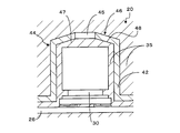
- FIG. 5 shows a resin frame 42 as a modification of the resin frame 31 shown in FIG. 3, FIG. 5 (A) is a plan view, and FIG. 5 (B) is a partial sectional view.
- the recess 44 that forms the concave holding portion 43 is provided with a vent hole 45 that can also be used as a resin injection hole, and the inner surface of the upper bottom surface 46 of the recess 44 is closer to the vent hole 45.
- a tapered portion 48 for reducing the resin sealing space 47 is formed. Since such a tapered portion 48 is formed on the upper bottom surface 46 of the recess 44, a gas such as air can easily escape from the resin sealing space 47 corresponding to each recess 44, and the filling resin Air bubbles are reliably prevented from remaining inside.
- FIG. 6 is a schematic cross-sectional view in the vicinity of the concave portion 44 of the substrate 26 shown in FIG. 3.
- the resin is placed in the resin sealing space 47 and the accommodation space 20.
- a filled example is shown.
- FIG. 6 shows a case where the insulating resin 35 is filled in the housing space 20 and the resin sealing space 47 is filled.
- the recess 44 is provided with a vent hole 45 that can also be used as a resin injection hole, the resin filling space 47 and the housing space 20 can be filled with resin simultaneously, shortening the resin filling process. In addition, the cost can be reduced.
- tapered portion 48 provided around the vent hole 45 in the upper bottom surface 46 of the concave portion 44 further prevents the generation or residual of bubbles in the resin sealing space 34 and the accommodating space 20, and the circuit component 30 can be fixed. Achieved more reliably.
- the present invention can be applied to all types of inverter-integrated electric compressors, and in particular, excellent operational stability and vibration resistance are required, the required level of design freedom is high, and miniaturization and weight reduction are required. It is suitable as an inverter-integrated electric compressor for a vehicle air conditioner.
Landscapes
- Engineering & Computer Science (AREA)
- Mechanical Engineering (AREA)
- General Engineering & Computer Science (AREA)
- Compressor (AREA)
- Applications Or Details Of Rotary Compressors (AREA)
Abstract
Description
れることにより、樹脂封入用空間内もしくは収容空間内への樹脂充填時における樹脂フレームの所定位置からのずれの発生が防止され、そのようなずれに起因する樹脂内での気泡の発生や充填漏れが防止され、回路部品の固定が確実に達成される。
図1は、本発明の一実施態様に係るインバータ一体型電動圧縮機を示しており、とくに、スクロール型電動圧縮機に本発明を適用した例を示している。図1において、インバータ一体型電動圧縮機1は、固定スクロール3および可動スクロール4からなる圧縮機構2を備えている。可動スクロール4は、ボールカップリング5を介して自転が阻止された状態で、固定スクロール3に対して旋回されるようになっている。圧縮機ハウジング(センターハウジング)6内には、モータ7が組み込まれており、この内蔵モータ7によって主軸8(回転軸)が回転駆動される。主軸8の一端側に配設された偏心ピン9、それに対して回転自在に係合された偏心ブッシュ10を介して、主軸8の回転運動が可動スクロール4の旋回運動に変換されるようになっている。本実施態様では、被圧縮流体としての冷媒を吸入する吸入ポート11が圧縮機ハウジング(フロントハウジング)12に設けられており、吸入された冷媒は、モータ7配置部を通して圧縮機構2へと導かれ、圧縮機構2で圧縮された冷媒は、吐出孔13、吐出室14、圧縮機ハウジング(リアハウジング)15に設けられた吐出ポート16を通して外部回路に送られる。
出力端子)、リード線24を介してモータ7に給電し、密封端子23設置部では、冷媒吸入経路側とモータ駆動回路21設置側とがシールされている。本実施態様においては、モータ駆動回路21を仕切壁22の外面側に設けることによって、仕切壁22を介して、モータ駆動回路21を含む電気部品の少なくとも一部が吸入冷媒と熱交換可能に構成されており、吸入冷媒によって冷却可能となっている。このように構成することにより、発熱しやすい電気部品(例えば、インバータ機能を有するモータ駆動用高電圧回路)を自動的に適切に冷却でき、モータ駆動回路21の所定性能を維持できるとともに、別途冷却装置等を設ける必要がないため、構造の簡素化をはかることができる。なお、このような構成はスクロール型電動圧縮機のみに限定されず、被圧縮流体が冷媒であるあらゆる種類のインバータ一体型電動圧縮機に適用可能である。
2 圧縮機構
3 固定スクロール
4 可動スクロール
5 ボールカップリング
6 圧縮機ハウジング(センターハウジング)
7 モータ
8 主軸
9 偏心ピン
10 偏心ブッシュ
11 吸入ポート
12 圧縮機ハウジング(フロントハウジング)
13 吐出孔
14 吐出室
15 圧縮機ハウジング(リアハウジング)
16 吐出ポート
20 収容空間
21 モータ駆動回路
22 仕切壁
23 密封端子
24 リード線
25 IPM
26 基板
27 コンデンサ
28 コネクタ
29 蓋部材
30 回路部品
31、42 樹脂フレーム
32、43 凹状保持部
33、45 通気孔
34、47 樹脂封入用空間
35 絶縁用樹脂
36 ノイズフィルタ
37、44 凹部
38 位置決め用の孔
39 締結部
40 接着用樹脂
41 凹部の基板対向面
46 凹部の上底面
48 テーパ状部
Claims (12)
- モータが内蔵され、インバータを含むモータ駆動回路が設けられた基板を有するインバータ一体型電動圧縮機であって、前記基板を含む電気部品が圧縮機ハウジングで囲まれた収容空間内に固定され、組立完了後に、前記収容空間内に絶縁用樹脂が充填され、前記電気部品の少なくとも一部が固化された充填樹脂により密封されるインバータ一体型電動圧縮機において、
前記基板上に備えられた回路部品の外形に沿って凹状に成形された凹部を備えた凹状保持部と、該凹状保持部に設けられた通気孔とを有する樹脂フレームを、前記基板上に装着し、該基板上の回路部品と前記樹脂フレームとの間に、樹脂を充填可能な樹脂封入用空間を形成したことを特徴とするインバータ一体型電動圧縮機。 - 前記凹部は、前記通気孔周りに、前記通気孔に近づくほど前記樹脂封入用空間を縮小させるテーパ状部を有する、請求項1に記載のインバータ一体型電動圧縮機。
- 前記凹部が、実質的に前記基板上の回路部品ごとの外形に対応させて形成されている、請求項1または2に記載のインバータ一体型電動圧縮機。
- 前記収容空間内への絶縁用樹脂の充填とともに、該絶縁用樹脂の前記樹脂封入用空間内への充填が行われている、請求項1~3のいずれかに記載のインバータ一体型電動圧縮機。
- 前記樹脂封入用空間内に接着用樹脂が充填された後に、前記収容空間内への前記絶縁用樹脂の充填が行われている、請求項1~3のいずれかに記載のインバータ一体型電動圧縮機。
- 接着用樹脂注入器具の位置決め用の孔が前記樹脂フレームに設けられている、請求項5に記載のインバータ一体型電動圧縮機。
- 前記樹脂フレームに樹脂注入孔が設けられている、請求項1~6のいずれかに記載のインバータ一体型電動圧縮機。
- 複数の凹部のそれぞれに前記樹脂注入孔が設けられている、請求項7に記載のインバータ一体型電動圧縮機。
- 前記凹部は、前記樹脂注入孔周りに、前記樹脂注入孔に近づくほど前記樹脂封入用空間を縮小させるテーパ状部を有する、請求項7または8に記載のインバータ一体型電動圧縮機。
- 前記基板上に装着された前記樹脂フレームが基板に対して締結により固定されている、請求項1~9のいずれかに記載のインバータ一体型電動圧縮機。
- 車両に搭載される圧縮機からなる、請求項1~10のいずれかに記載のインバータ一体型電動圧縮機。
- 車両空調装置用の圧縮機からなる、請求項11に記載のインバータ一体型電動圧縮機。
Priority Applications (3)
| Application Number | Priority Date | Filing Date | Title |
|---|---|---|---|
| CN200980145423.XA CN102216616B (zh) | 2008-11-10 | 2009-11-10 | 逆变器一体型电动压缩机 |
| US13/128,613 US20110217190A1 (en) | 2008-11-10 | 2009-11-10 | Inverter-Integrated Electric Compressor |
| DE112009002719.9T DE112009002719B4 (de) | 2008-11-10 | 2009-11-10 | Elektrischer Kompressor mit integriertem Wechselrichter |
Applications Claiming Priority (4)
| Application Number | Priority Date | Filing Date | Title |
|---|---|---|---|
| JP2008-287688 | 2008-11-10 | ||
| JP2008287688 | 2008-11-10 | ||
| JP2009-119604 | 2009-05-18 | ||
| JP2009119604A JP5413829B2 (ja) | 2008-11-10 | 2009-05-18 | インバータ一体型電動圧縮機 |
Publications (1)
| Publication Number | Publication Date |
|---|---|
| WO2010052935A1 true WO2010052935A1 (ja) | 2010-05-14 |
Family
ID=42152748
Family Applications (1)
| Application Number | Title | Priority Date | Filing Date |
|---|---|---|---|
| PCT/JP2009/005979 Ceased WO2010052935A1 (ja) | 2008-11-10 | 2009-11-10 | インバータ一体型電動圧縮機 |
Country Status (5)
| Country | Link |
|---|---|
| US (1) | US20110217190A1 (ja) |
| JP (1) | JP5413829B2 (ja) |
| CN (1) | CN102216616B (ja) |
| DE (1) | DE112009002719B4 (ja) |
| WO (1) | WO2010052935A1 (ja) |
Cited By (2)
| Publication number | Priority date | Publication date | Assignee | Title |
|---|---|---|---|---|
| US20250146484A1 (en) * | 2022-02-22 | 2025-05-08 | Sanden Corporation | Electric compressor |
| US20250215869A1 (en) * | 2022-04-22 | 2025-07-03 | Sanden Corporation | Inverter-integrated electric compressor |
Families Citing this family (12)
| Publication number | Priority date | Publication date | Assignee | Title |
|---|---|---|---|---|
| JP5235312B2 (ja) * | 2007-02-22 | 2013-07-10 | サンデン株式会社 | インバータ一体型電動圧縮機の製造方法 |
| JP5308917B2 (ja) * | 2009-05-29 | 2013-10-09 | サンデン株式会社 | インバータ一体型電動圧縮機 |
| CN104718804B (zh) * | 2012-10-03 | 2018-10-23 | 新电元工业株式会社 | 电子设备 |
| JP2015014203A (ja) * | 2013-07-03 | 2015-01-22 | サンデン株式会社 | 電動圧縮機の電気回路耐振構造 |
| CN104604346B (zh) | 2013-08-30 | 2016-04-20 | 新电元工业株式会社 | 电气设备及其制造方法、以及电气设备的设计方法 |
| JP2015121196A (ja) * | 2013-12-25 | 2015-07-02 | 株式会社豊田自動織機 | 電動圧縮機用の半導体装置 |
| JP6444605B2 (ja) * | 2014-03-19 | 2018-12-26 | 三菱重工サーマルシステムズ株式会社 | インバータ一体型電動圧縮機 |
| JP6295974B2 (ja) * | 2015-02-10 | 2018-03-20 | マツダ株式会社 | 検査方法 |
| JP6910315B2 (ja) * | 2018-02-23 | 2021-07-28 | サンデン・オートモーティブコンポーネント株式会社 | 電動圧縮機 |
| KR102645188B1 (ko) * | 2018-09-05 | 2024-03-11 | 엘지이노텍 주식회사 | 전동식 오일 펌프의 제어 모듈 |
| JP7596066B2 (ja) | 2019-09-12 | 2024-12-09 | オムロン株式会社 | 電子機器、非接触スイッチ、および光電センサ |
| CN115638104A (zh) * | 2021-07-19 | 2023-01-24 | 杭州奥科美瑞科技有限公司 | 流体驱动装置 |
Citations (5)
| Publication number | Priority date | Publication date | Assignee | Title |
|---|---|---|---|---|
| JPH0955585A (ja) * | 1995-08-11 | 1997-02-25 | Matsushita Electric Works Ltd | 部品収納装置 |
| JP2002070743A (ja) * | 2000-08-29 | 2002-03-08 | Sanden Corp | 冷媒圧縮用電動式圧縮機 |
| JP2007081047A (ja) * | 2005-09-13 | 2007-03-29 | Toshiba Lighting & Technology Corp | 電子機器、点灯装置、及び照明器具 |
| JP2008202565A (ja) * | 2007-02-22 | 2008-09-04 | Sanden Corp | インバータ一体型電動圧縮機 |
| JP2008243908A (ja) * | 2007-03-26 | 2008-10-09 | Matsushita Electric Ind Co Ltd | 回路基板および電子機器 |
Family Cites Families (16)
| Publication number | Priority date | Publication date | Assignee | Title |
|---|---|---|---|---|
| JP3086819B2 (ja) | 1990-07-20 | 2000-09-11 | セイコーエプソン株式会社 | 空気調和機用モータ一体型圧縮機 |
| JP2875139B2 (ja) * | 1993-07-15 | 1999-03-24 | 株式会社東芝 | 半導体装置の製造方法 |
| JP4080554B2 (ja) * | 1995-12-06 | 2008-04-23 | ダイキン工業株式会社 | テトラフルオロエチレンの乳化重合方法 |
| JP2000186931A (ja) * | 1998-12-21 | 2000-07-04 | Murata Mfg Co Ltd | 小型電子部品及びその製造方法並びに該小型電子部品に用いるビアホールの成形方法 |
| JP2001196770A (ja) * | 2000-01-12 | 2001-07-19 | Omron Corp | コントロールユニット |
| JP4091838B2 (ja) * | 2001-03-30 | 2008-05-28 | 富士通株式会社 | 半導体装置 |
| EP1363026A3 (en) * | 2002-04-26 | 2004-09-01 | Denso Corporation | Invertor integrated motor for an automotive vehicle |
| JP2004237500A (ja) * | 2003-02-04 | 2004-08-26 | Canon Inc | 樹脂成形品の製造方法 |
| JP2007305749A (ja) * | 2006-05-10 | 2007-11-22 | Toshiba Corp | 半導体装置およびその製造方法 |
| JP5141076B2 (ja) * | 2006-06-05 | 2013-02-13 | 株式会社デンソー | 半導体装置 |
| US8007255B2 (en) * | 2006-11-22 | 2011-08-30 | Mitsubishi Heavy Industries, Ltd. | Inverter-integrated electric compressor with inverter storage box arrangement |
| JP4764365B2 (ja) * | 2007-02-28 | 2011-08-31 | 三菱重工業株式会社 | インバータ一体型電動圧縮機 |
| JP2008267179A (ja) * | 2007-04-17 | 2008-11-06 | Denso Corp | 電動コンプレッサ |
| JP2009064916A (ja) * | 2007-09-05 | 2009-03-26 | Kokusan Denki Co Ltd | 電子ユニット及びその製造方法 |
| JP4764395B2 (ja) * | 2007-09-21 | 2011-08-31 | 三菱重工業株式会社 | インバータ一体型電動圧縮機 |
| JP5107114B2 (ja) * | 2008-03-28 | 2012-12-26 | 三菱重工業株式会社 | インバータ一体型電動圧縮機 |
-
2009
- 2009-05-18 JP JP2009119604A patent/JP5413829B2/ja active Active
- 2009-11-10 US US13/128,613 patent/US20110217190A1/en not_active Abandoned
- 2009-11-10 WO PCT/JP2009/005979 patent/WO2010052935A1/ja not_active Ceased
- 2009-11-10 CN CN200980145423.XA patent/CN102216616B/zh not_active Expired - Fee Related
- 2009-11-10 DE DE112009002719.9T patent/DE112009002719B4/de not_active Expired - Fee Related
Patent Citations (5)
| Publication number | Priority date | Publication date | Assignee | Title |
|---|---|---|---|---|
| JPH0955585A (ja) * | 1995-08-11 | 1997-02-25 | Matsushita Electric Works Ltd | 部品収納装置 |
| JP2002070743A (ja) * | 2000-08-29 | 2002-03-08 | Sanden Corp | 冷媒圧縮用電動式圧縮機 |
| JP2007081047A (ja) * | 2005-09-13 | 2007-03-29 | Toshiba Lighting & Technology Corp | 電子機器、点灯装置、及び照明器具 |
| JP2008202565A (ja) * | 2007-02-22 | 2008-09-04 | Sanden Corp | インバータ一体型電動圧縮機 |
| JP2008243908A (ja) * | 2007-03-26 | 2008-10-09 | Matsushita Electric Ind Co Ltd | 回路基板および電子機器 |
Cited By (2)
| Publication number | Priority date | Publication date | Assignee | Title |
|---|---|---|---|---|
| US20250146484A1 (en) * | 2022-02-22 | 2025-05-08 | Sanden Corporation | Electric compressor |
| US20250215869A1 (en) * | 2022-04-22 | 2025-07-03 | Sanden Corporation | Inverter-integrated electric compressor |
Also Published As
| Publication number | Publication date |
|---|---|
| DE112009002719B4 (de) | 2016-03-10 |
| JP5413829B2 (ja) | 2014-02-12 |
| US20110217190A1 (en) | 2011-09-08 |
| JP2010133400A (ja) | 2010-06-17 |
| DE112009002719T5 (de) | 2013-02-28 |
| CN102216616A (zh) | 2011-10-12 |
| CN102216616B (zh) | 2014-06-25 |
Similar Documents
| Publication | Publication Date | Title |
|---|---|---|
| JP5413829B2 (ja) | インバータ一体型電動圧縮機 | |
| KR100937127B1 (ko) | 전동 컴프레서 | |
| JP5291436B2 (ja) | インバータ一体型電動圧縮機 | |
| KR101785398B1 (ko) | 인버터 및 전동 압축기 | |
| JP5209259B2 (ja) | 駆動回路一体型電動圧縮機 | |
| EP2461039B1 (en) | Electric compressor | |
| JP5413435B2 (ja) | 電動コンプレッサ | |
| KR102191420B1 (ko) | 공기 조화 시스템의 전기 압축기용 모터 하우징 | |
| CN101617121B (zh) | 逆变器一体型的电动压缩机 | |
| CN107534354A (zh) | 电动压缩机用马达外壳以及使用该马达外壳的车载用电动压缩机 | |
| WO2014073159A1 (ja) | 高電圧電気装置及び電動圧縮機 | |
| JP3997855B2 (ja) | 電動コンプレッサ | |
| JP5235312B2 (ja) | インバータ一体型電動圧縮機の製造方法 | |
| KR20230087587A (ko) | 전기 냉매 압축기의 전자 부품용 하우징 유닛 | |
| JP7263058B2 (ja) | 電動圧縮機 | |
| WO2006129448A1 (ja) | 電動圧縮機 | |
| JP4749729B2 (ja) | 電動圧縮機 | |
| JP4884841B2 (ja) | インバータ一体型電動圧縮機 | |
| KR20100018227A (ko) | 전동식 압축기용 인버터 하우징 | |
| JP5007266B2 (ja) | 電動コンプレッサ | |
| CN221299552U (zh) | 一种底部灌胶的薄风扇 | |
| JP2006200519A (ja) | 電動圧縮機 | |
| JP5007265B2 (ja) | 電動コンプレッサ | |
| JPWO2025062520A5 (ja) | ||
| JP2009257291A (ja) | 電動コンプレッサ |
Legal Events
| Date | Code | Title | Description |
|---|---|---|---|
| WWE | Wipo information: entry into national phase |
Ref document number: 200980145423.X Country of ref document: CN |
|
| 121 | Ep: the epo has been informed by wipo that ep was designated in this application |
Ref document number: 09824635 Country of ref document: EP Kind code of ref document: A1 |
|
| WWE | Wipo information: entry into national phase |
Ref document number: 13128613 Country of ref document: US |
|
| WWE | Wipo information: entry into national phase |
Ref document number: 1120090027199 Country of ref document: DE |
|
| 122 | Ep: pct application non-entry in european phase |
Ref document number: 09824635 Country of ref document: EP Kind code of ref document: A1 |