WO2010052887A1 - 熱交換器及びこれを用いた給湯装置 - Google Patents
熱交換器及びこれを用いた給湯装置 Download PDFInfo
- Publication number
- WO2010052887A1 WO2010052887A1 PCT/JP2009/005823 JP2009005823W WO2010052887A1 WO 2010052887 A1 WO2010052887 A1 WO 2010052887A1 JP 2009005823 W JP2009005823 W JP 2009005823W WO 2010052887 A1 WO2010052887 A1 WO 2010052887A1
- Authority
- WO
- WIPO (PCT)
- Prior art keywords
- pipe
- heat exchanger
- hot water
- pipes
- water supply
- Prior art date
- Legal status (The legal status is an assumption and is not a legal conclusion. Google has not performed a legal analysis and makes no representation as to the accuracy of the status listed.)
- Ceased
Links
Images




Classifications
-
- F—MECHANICAL ENGINEERING; LIGHTING; HEATING; WEAPONS; BLASTING
- F28—HEAT EXCHANGE IN GENERAL
- F28D—HEAT-EXCHANGE APPARATUS, NOT PROVIDED FOR IN ANOTHER SUBCLASS, IN WHICH THE HEAT-EXCHANGE MEDIA DO NOT COME INTO DIRECT CONTACT
- F28D7/00—Heat-exchange apparatus having stationary tubular conduit assemblies for both heat-exchange media, the media being in contact with different sides of a conduit wall
- F28D7/02—Heat-exchange apparatus having stationary tubular conduit assemblies for both heat-exchange media, the media being in contact with different sides of a conduit wall the conduits being helically coiled
- F28D7/022—Heat-exchange apparatus having stationary tubular conduit assemblies for both heat-exchange media, the media being in contact with different sides of a conduit wall the conduits being helically coiled the conduits of two or more media in heat-exchange relationship being helically coiled, the coils having a cylindrical configuration
-
- C—CHEMISTRY; METALLURGY
- C25—ELECTROLYTIC OR ELECTROPHORETIC PROCESSES; APPARATUS THEREFOR
- C25F—PROCESSES FOR THE ELECTROLYTIC REMOVAL OF MATERIALS FROM OBJECTS; APPARATUS THEREFOR
- C25F3/00—Electrolytic etching or polishing
- C25F3/16—Polishing
- C25F3/22—Polishing of heavy metals
-
- F—MECHANICAL ENGINEERING; LIGHTING; HEATING; WEAPONS; BLASTING
- F24—HEATING; RANGES; VENTILATING
- F24D—DOMESTIC- OR SPACE-HEATING SYSTEMS, e.g. CENTRAL HEATING SYSTEMS; DOMESTIC HOT-WATER SUPPLY SYSTEMS; ELEMENTS OR COMPONENTS THEREFOR
- F24D17/00—Domestic hot-water supply systems
- F24D17/02—Domestic hot-water supply systems using heat pumps
-
- F—MECHANICAL ENGINEERING; LIGHTING; HEATING; WEAPONS; BLASTING
- F28—HEAT EXCHANGE IN GENERAL
- F28D—HEAT-EXCHANGE APPARATUS, NOT PROVIDED FOR IN ANOTHER SUBCLASS, IN WHICH THE HEAT-EXCHANGE MEDIA DO NOT COME INTO DIRECT CONTACT
- F28D7/00—Heat-exchange apparatus having stationary tubular conduit assemblies for both heat-exchange media, the media being in contact with different sides of a conduit wall
- F28D7/0066—Multi-circuit heat-exchangers, e.g. integrating different heat exchange sections in the same unit or heat-exchangers for more than two fluids
-
- F—MECHANICAL ENGINEERING; LIGHTING; HEATING; WEAPONS; BLASTING
- F28—HEAT EXCHANGE IN GENERAL
- F28D—HEAT-EXCHANGE APPARATUS, NOT PROVIDED FOR IN ANOTHER SUBCLASS, IN WHICH THE HEAT-EXCHANGE MEDIA DO NOT COME INTO DIRECT CONTACT
- F28D7/00—Heat-exchange apparatus having stationary tubular conduit assemblies for both heat-exchange media, the media being in contact with different sides of a conduit wall
- F28D7/0066—Multi-circuit heat-exchangers, e.g. integrating different heat exchange sections in the same unit or heat-exchangers for more than two fluids
- F28D7/0075—Multi-circuit heat-exchangers, e.g. integrating different heat exchange sections in the same unit or heat-exchangers for more than two fluids with particular circuits for the same heat exchange medium, e.g. with the same heat exchange medium flowing through sections having different heat exchange capacities or for heating or cooling the same heat exchange medium at different temperatures
-
- F—MECHANICAL ENGINEERING; LIGHTING; HEATING; WEAPONS; BLASTING
- F28—HEAT EXCHANGE IN GENERAL
- F28F—DETAILS OF HEAT-EXCHANGE AND HEAT-TRANSFER APPARATUS, OF GENERAL APPLICATION
- F28F19/00—Preventing the formation of deposits or corrosion, e.g. by using filters or scrapers
Definitions
- the present invention relates to a heat exchanger used as, for example, a water heat exchanger of a heat pump hot water supply apparatus and a hot water supply apparatus using the heat exchanger.
- this type of heat pump type hot water supply apparatus has a heating unit that heats hot water supply water by a heat pump circuit and a tank unit that stores hot water generated by the heating unit, and supplies the hot water of the tank unit to a bathtub or a kitchen. What was made to do is known (for example, refer patent document 1).
- the heating unit of this hot water supply apparatus includes a refrigerant circuit composed of a compressor, an evaporator, a water heat exchanger (gas cooler), etc., heats hot water supply water with the water heat exchanger, and supplies it to the tank unit via the hot water pipe. I am doing so.
- the water heat exchanger of the hot water supply apparatus includes an inner pipe through which the high-temperature refrigerant of the heat pump circuit circulates and an outer pipe in which the inner pipe is disposed, and hot water is supplied between the inner pipe and the outer pipe. By circulating, the refrigerant and the hot water supply water are configured to exchange heat through the inner pipe.
- the inner pipe and the outer pipe are easily attached with a so-called scale mainly composed of calcium carbonate or the like contained in hot water supply water, and particularly when the refrigerant and the hot water supply water are used as counterflows, particularly downstream of the hot water supply water.
- the scale adheres firmly to the side (high temperature side) and accumulates, thereby obstructing the flow of hot water. Therefore, conventionally, the entire outer pipe or only the downstream side is formed by a pipe having a large diameter, so that a sufficient cross-sectional area of flow between the inner pipe and the outer pipe is secured, and even if scale is deposited, Distribution is not hindered.
- the present invention has been made in view of the above-mentioned problems, and the object of the present invention is to effectively prevent the flow inhibition due to the accumulation of scale without forming the entire outer tube or only the downstream side with a tube having a large diameter.
- An object of the present invention is to provide a heat exchanger that can be prevented and a hot water supply device using the same.
- the present invention includes a heat-conductive inner tube that circulates a first heat medium, and an outer tube having an inner tube disposed therein, and the first tube is disposed between the inner tube and the outer tube.
- the heat exchanger configured to exchange heat between the first heat medium and the second heat medium through the inner pipe by circulating the second heat medium, the inner side downstream of the second heat medium.
- a copper pipe configured such that the number of pipes is less than the number of inner pipes upstream of the second heat medium, and at least one of the inner pipe and the outer pipe is processed to reduce the surface roughness, or A copper alloy tube is used.
- the number of the inner pipes on the downstream side of the second heat medium is smaller than the number of the inner pipes on the upstream side, between the outer pipe and the inner pipe on the downstream side of the second heat medium, Even if the flow cross-sectional area larger than between the outer pipe and the inner pipe on the upstream side is ensured, for example, the scale is deposited on the downstream side of the hot water as the second heat medium, the flow of the second heat medium is There is no hindrance.
- the number of the inner pipes on the upstream side of the second heat medium is larger than that on the downstream side, the second heat medium is sufficiently heated by the inner pipe on the upstream side.
- at least one of the inner tube and the outer tube is made of a copper tube or a copper alloy tube that has been processed to reduce the surface roughness, adhesion of scale between the outer tube and the inner tube is suppressed. be able to.
- the present invention it is possible to ensure a larger flow cross-sectional area between the outer pipe and the inner pipe on the downstream side of the second heat medium than between the outer pipe and the inner pipe on the upstream side. Even if the entire pipe or only the outer pipe on the downstream side is not formed by a pipe having a large diameter, it is possible to effectively prevent the flow inhibition in the outer pipe on the downstream side due to the accumulation of scale. Therefore, since the kind and cost of the pipe used as the material of the outer pipe are not increased, productivity can be improved. In this case, since the second heat medium can be sufficiently heated by the inner pipe on the upstream side of the second heat medium, there is an advantage that the overall heat exchange efficiency is not lowered. Furthermore, scale adhesion between the outer tube and the inner tube can be suppressed, which is effective in preventing scale accumulation.
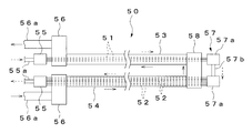
- the schematic block diagram of the heat pump type hot-water supply apparatus which shows one Embodiment of this invention Schematic side view of the first water heat exchanger Top view of the first water heat exchanger Side view of the first water heat exchanger Sectional view taken along line XX in FIG.
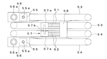
- the top view of the 1st water heat exchanger showing other embodiments of the present invention Side view of the first water heat exchanger YY arrow direction sectional view in FIG.
- the objective of inputting images from the position outside the housing or as close as possible to the end on the side of the housing was realized with the minimum number of parts and without sacrificing the thickness of the optical system components.
- FIG. 1 is a schematic configuration diagram of a heat pump type hot water supply apparatus
- FIG. 2 is a schematic configuration diagram of a first water heat exchanger
- FIG. 3 is a plan view thereof. 4 is a side view thereof
- FIG. 5 is a cross-sectional view in the direction of arrows XX in FIG.
- the heat pump type hot water supply apparatus shown in FIG. 1 circulates a refrigerant circuit 10 that circulates refrigerant, a first hot water supply circuit 20 that circulates hot water supply water, a second hot water supply circuit 30 that circulates hot water supply water, and bathtub water.
- a second water heat exchanger 60 for exchanging heat with the bathtub water, and the first water heat exchanger 50 constitutes the heat exchanger of the present invention.
- the refrigerant circuit 10 is formed by connecting the compressor 11, the expansion valve 12, the air heat exchanger 13, and the first water heat exchanger 50, and includes the compressor 11, the first water heat exchanger 50, the expansion valve 12, The refrigerant is circulated in the order of the air heat exchanger 13 and the compressor 11.
- the refrigerant used in the refrigerant circuit 10 is a natural refrigerant such as carbon dioxide.
- the first hot water supply circuit 20 is formed by connecting a hot water storage tank 21, a first pump 22, and a first water heat exchanger 50, and the hot water storage tank 21, the first pump 22, and the first water heat exchanger 50 are connected.
- the hot water supply water is circulated in the order of the hot water storage tank 21.
- a water supply pipe 23 and a second hot water supply circuit 30 are connected to the hot water storage tank 21, and hot water supplied from the water supply pipe 23 flows through the first hot water supply circuit 20 through the hot water storage tank 21.
- the hot water storage tank 21 and the bathtub 41 are connected via a flow path 25 provided with a second pump 24, and the hot water in the hot water storage tank 21 is supplied to the bathtub 41 by the second pump 24. ing.
- the second hot water supply circuit 30 is formed by connecting the hot water storage tank 21, the third pump 31, and the second water heat exchanger 60, and the hot water storage tank 21, the second water heat exchanger 60, and the third pump 31.
- the hot water supply water is circulated in the order of the hot water storage tank 21.
- the bathtub circuit 40 is formed by connecting the bathtub 41, the fourth pump 42, and the second water heat exchanger 60.
- the bathtub 41, the fourth pump 42, the second water heat exchanger 60, and the bathtub 41 are connected to each other.
- the water for bathtubs is circulated in order.
- the first water heat exchanger 50 is connected to the refrigerant circuit 10 and the first hot water supply circuit 20, and is connected to the refrigerant as the first heat medium flowing through the refrigerant circuit 10 and the second hot water circuit 20. Heat exchange is performed with hot water supply water as a heat medium.
- the first water heat exchanger 50 includes a first heat transferable first and second inner pipes 51 and 52 through which a refrigerant flows, and a first and second inner pipes 51 and 52 disposed therein.
- first end headers 55 to which one ends of the first and second inner pipes 51 and 52 are connected, respectively, and the first and second outer pipes 53 and 54, 54, a pair of second end headers 56 each connected to one end, a first intermediate header 57 to which the other ends of the first and second inner pipes 51 and 52 are connected, and first and second The inner pipes 51 and 52 and the outer pipes 53 and 54 are wound in a spiral shape.
- two first inner pipes 51 are arranged in the first outer pipe 53
- four second inner pipes 52 are arranged in the second outer pipe 54.
- Each first end header 55 is connected to the refrigerant circuit 10 and is connected to an inflow pipe 55a and an outflow pipe 55b of the refrigerant, respectively.
- the first inner pipes 51 are connected in parallel to the first end header 55 on the inflow side
- the second inner pipes 52 are connected to the first end header 55 on the outflow side.
- Each second end header 56 is connected to the first hot water supply circuit 20, and an inflow pipe 56 a and an outflow pipe 55 b are connected to the hot water supply water, respectively.
- each second inner pipe 52 penetrates through the second end header 56 on the inflow side
- each first inner pipe 51 penetrates through the second end header 56 on the outflow side. ing.
- the first intermediate header 57 includes a pair of header portions 57a and a communication pipe 57b that connects the header portions 57a to each other.
- the first inner pipes 51 are connected in parallel to one header portion 57a.
- the second inner pipes 52 are connected in parallel to the other header portion 57a.
- the first intermediate header 57 is connected to the first and second inner pipes 51 and 52 from the same direction.
- First and second outer pipes 53 and 54 are connected to the second intermediate header 58 from the same direction, and the first and second inner pipes 51 and 52 pass therethrough, respectively.
- first inner tube 51 and the first outer tube 53 have a winding portion A1 wound around from the outside to the inside and a winding portion A2 wound around from the inside toward the outside.
- the pipes of the winding parts A1 and A2 are formed so as to be continuous by shifting the pipes in the vertical direction inside the winding parts A1 and A2.
- the second inner tube 52 and the second outer tube 54 have a winding part A2 wound from the inside to the outside and a winding part A1 wound from the outside to the inside in two upper and lower stages.
- the pipes of the winding portions A1 and A2 are formed so as to be continuous by arranging the pipes in the vertical direction inside the winding portions A1 and A2.
- the winding portions A1 and A2 of the first inner tube 51 and the first outer tube 53 are arranged above the winding portions A1 and A2 of the second inner tube 52 and the second outer tube 54, respectively.
- the parts A1 and A2 are arranged in four upper and lower stages.
- the first and second inner pipes 51 and 52 are made of a copper pipe or a copper alloy pipe that has been subjected to a process for reducing the surface roughness, and is subjected to a polishing process by, for example, electrolytic polishing.
- Electropolishing is a well-known polishing method in which an external current is passed through an electrolytic solution to reduce the surface roughness of the metal by electrolysis of the metal, and the first and second inner pipes 51 and 52 have a surface roughness. Is polished to 1.0 ⁇ m or less.
- the second water heat exchanger 60 is connected to the second hot water supply circuit 30 and the bathtub circuit 40 and exchanges heat between the hot water supply water of the second hot water supply circuit 30 and the bathtub water of the bathtub circuit 40. ing.
- the hot water supply apparatus includes a heating unit 70 in which the refrigerant circuit 10 and the first water heat exchanger 50 are arranged, a hot water storage tank 21, a first pump 22, a second pump 24, and a second hot water supply circuit 30.
- the tank unit 80 in which the fourth pump 42 and the second water heat exchanger 60 are arranged is provided, and the heating unit 70 and the tank unit 80 are connected via the first hot water supply circuit 20.
- the high temperature refrigerant of the refrigerant circuit 10 and the hot water for the hot water supply circuit 20 are heat-exchanged by the first water heat exchanger 50, and the hot water for hot water is heated.
- the refrigerant in the refrigerant circuit 10 flows into the first inner pipes 51 through the first end header 55, After flowing through each first inner pipe 51, it flows into each second inner pipe 52 via the first intermediate header 57, and after flowing through each second inner pipe 52, the other first end It flows out to the outside through the section header 55.
- the hot water for the hot water supply circuit 20 flows into the second outer pipe 54 via the second end header 56, and the second outer pipe 54 and each After flowing between the two inner pipes 52, it flows into the first outer pipe 53 via the second intermediate header 58, and passes between the first outer pipe 53 and each first inner pipe 51. After distribution, the liquid flows out through the other second end header 56. That is, in the first water heat exchanger 50, the refrigerant and hot water supply water flow in opposite directions.
- the first outer pipes 53 and the first inner pipes A larger flow cross-sectional area than between the second outer pipe 54 and each second inner pipe 52 is ensured between the pipe 51 and the hot water supply water even if the scale accumulates on the downstream side of the hot water supply water. Distribution is not hindered.
- the number of second inner pipes 52 on the upstream side of the hot water supply water is larger than that of the first inner pipes 51 on the downstream side, the hot water supply water is sufficiently heated by each second inner pipe 52.
- the first and second inner pipes 51 and 52 are made of copper pipes or copper alloy pipes having a small surface roughness, scale adhesion to the outer peripheral surfaces of the inner pipes 51 and 52 is suppressed.
- the number of the first inner pipes 51 on the downstream side of the hot water supply water is made smaller than the number of the second inner pipes 52 on the upstream side, so that Since a larger cross-sectional area can be secured between the pipe 53 and each first inner pipe 51 than between the second outer pipe 54 and each second inner pipe 52, the outer pipe 53, Even if the entire 54 or only the outer pipe 53 on the downstream side is not formed by a pipe having a large diameter, it is possible to effectively prevent the flow inhibition in the downstream outer pipe 53 due to the accumulation of scale. Therefore, productivity can be improved without increasing the types and costs of the tubes used as the materials of the outer tubes 53 and 54.
- each of the second inner pipes 52 on the upstream side of the hot water supply water is larger than that of the first inner pipes 51 on the downstream side, each of the second inner pipes 52 can sufficiently heat the hot water supply water. There is an advantage that the overall heat exchange efficiency is not lowered.
- first and second inner pipes 51 and 52 are copper pipes or copper alloy pipes that have been processed to reduce the surface roughness
- the outer pipes 53 and 54 and the inner pipes 51 and 52 It is possible to suppress the adhesion of the scale between the two, which is effective in preventing the deposition of the scale.
- electrolytic polishing is used as a process for reducing the surface roughness, the surface can be smoothly and easily finished in a short time compared to, for example, a mechanical polishing method using an abrasive.
- the cost of the copper pipe or copper alloy pipe used for 52 can be reduced.
- first inner pipe 51 and the first outer pipe 53, the second inner pipe 52 and the second outer pipe 54 are connected from the same direction between the upstream side and the downstream side of the hot water supply water. Since the first and second intermediate headers 57 and 58 are provided and the pipe lines are folded back at the intermediate headers 57 and 58, the inner pipes 51 and 52 and the outer pipes 53 and 54 do not become long. The entire first water heat exchanger 50 can be downsized.
- the inner pipes 51 and 52 and the outer pipes 53 and 54 are wound in a spiral shape, and a winding portion A1 that is wound from the outside to the inside, and a winding that is wound from the inside to the outside. Since the parts A2 are arranged in the vertical direction, and the pipes of the winding parts A1, A2 are formed continuously by shifting the pipes in the vertical direction inside the adjacent winding parts A1, A2.
- the inner pipes 51 and 52 and the outer pipes 53 and 54 having a large length can be wound efficiently, which is extremely advantageous for downsizing.
- the pipes are shifted inside the adjacent winding parts A1 and A2, but the pipes may be shifted outside the winding parts A1 and A2.
- the outer pipes 53 and 54 or the inner pipe 51 was shown.
- 52 and outer pipes 53, 54 may be copper pipes or copper alloy pipes that have been processed to reduce the surface roughness.
- a copper tube or a copper alloy tube in which at least one of the first inner tube 51 and the first outer tube 53 on the downstream side where scales are likely to be deposited is processed to reduce the surface roughness is used, and the upstream side
- the second inner pipe 52 and the second outer pipe 54 may be copper pipes or copper alloy pipes that are not processed to reduce the surface roughness. It is also possible to use a copper tube or a copper alloy tube that has been processed to reduce the surface roughness by a polishing method other than electrolytic polishing.
- FIG. 6 is a plan view of the first water heat exchanger
- FIG. 7 is a side view thereof
- FIG. 8 is a YY arrow in FIG. FIG.
- symbol is attached
- the winding parts A1 and A2 from the bottom to the second stage are on one side of the other winding parts A1 and A2 (each winding part A1).
- the extension part 54a when the extension part 54a is not provided, the extension part 54a can be arranged in the space below the evaporator 13 which becomes a dead space, so the second outer tube 54 is provided by the amount having the extension part 54a.
- the capacity can be increased by increasing the length, and the capacity of the first water heat exchanger 50 can be improved.
- the hot water supply water can be sufficiently heated by ensuring a flow cross-sectional area without hindering the flow of hot water supply due to scale adhesion in the water heat exchanger, and the heat exchange efficiency can not be lowered. It can be widely used as a water heat exchanger for hot water supply, and is particularly suitable as a water heat exchanger for a heat pump hot water supply apparatus.
Landscapes
- Engineering & Computer Science (AREA)
- Physics & Mathematics (AREA)
- General Engineering & Computer Science (AREA)
- Mechanical Engineering (AREA)
- Thermal Sciences (AREA)
- Chemical & Material Sciences (AREA)
- Materials Engineering (AREA)
- Organic Chemistry (AREA)
- Metallurgy (AREA)
- Electrochemistry (AREA)
- Chemical Kinetics & Catalysis (AREA)
- Combustion & Propulsion (AREA)
- Heat-Pump Type And Storage Water Heaters (AREA)
- Heat-Exchange Devices With Radiators And Conduit Assemblies (AREA)
- Details Of Fluid Heaters (AREA)
- Steam Or Hot-Water Central Heating Systems (AREA)
Abstract
【課題】外管の全体または下流側のみを径の大きい管によって形成せずとも、スケールの堆積による流通阻害を効果的に防止することのできる熱交換器及びこれを用いた給湯装置を提供する。 【解決手段】給湯用水の下流側となる第1の内管51の本数を上流側となる第2の内管52の本数よりも少なくすることにより、第1の外管53と各第1の内管51との間に、第2の外管54と各第2の内管52との間よりも大きい流通断面積を確保することができるので、外管53,54の全体または下流側の外管53のみを径の大きい管によって形成せずとも、スケールの堆積による下流側の外管53内の流通阻害を効果的に防止することができる。この場合、第1及び第2の内管51,52に、表面粗さを小さくする加工が施された銅管または銅合金管を用いたので、内管51,52へのスケールの付着を抑制することができる。
Description
本発明は、例えばヒートポンプ式給湯装置の水熱交換器として用いられる熱交換器及びこれを用いた給湯装置に関するものである。
従来、この種のヒートポンプ式給湯装置としては、ヒートポンプ回路によって給湯用水を加熱する加熱ユニットと、加熱ユニットで生成された温水を貯溜するタンクユニットとを備え、タンクユニットの温水を浴槽や台所に供給するようにしたものが知られている(例えば、特許文献1参照。)。
この給湯装置の加熱ユニットは、圧縮機、蒸発器、水熱交換器(ガスクーラ)等からなる冷媒回路を備え、給湯用水を水熱交換器で加熱し、温水配管を介してタンクユニットに供給するようにしている。また、前記給湯装置の水熱交換器は、ヒートポンプ回路の高温冷媒を流通する内管と、内管が内部に配置された外管とからなり、内管と外管との間に給湯用水を流通することにより、内管を介して冷媒と給湯用水とを熱交換するように構成されている。
ところで、前記内管及び外管には、給湯用水に含まれる炭酸カルシウム等を主成分とする、いわゆるスケールが付着しやすく、冷媒と給湯用水とを対向流とした場合は、特に給湯用水の下流側(高温側)にスケールが強固に付着して堆積し、給湯用水の流通を阻害するという問題がある。そこで、従来では外管の全体または下流側のみを径の大きい管によって形成することにより、内管と外管との間の流通断面積を十分に確保し、スケールが堆積しても給湯用水の流通が阻害されないようにしている。
しかしながら、外管の全体または下流側のみを径の大きい管によって形成すると、外管の材料となる管の種類やコストが増加し、生産性を低下させるという問題点があった。
本発明は前記問題点に鑑みてなされたものであり、その目的とするところは、外管の全体または下流側のみを径の大きい管によって形成せずとも、スケールの堆積による流通阻害を効果的に防止することのできる熱交換器及びこれを用いた給湯装置を提供することにある。
本発明は前記目的を達成するために、第1の熱媒体を流通する伝熱性の内管と、内管が内部に配置された外管とを備え、内管と外管との間に第2の熱媒体を流通することにより、内管を介して第1の熱媒体と第2の熱媒体とを熱交換するようにした熱交換器において、前記第2の熱媒体の下流側の内管の本数が第2の熱媒体の上流側の内管の本数よりも少なくなるように構成し、内管及び外管の少なくとも一方に、表面粗さを小さくする加工が施された銅管または銅合金管を用いている。
これにより、第2の熱媒体の下流側の内管の本数が上流側の内管の本数よりも少ないことから、第2の熱媒体の下流側の外管と内管との間には、上流側の外管と内管との間よりも大きい流通断面積が確保され、例えば第2の熱媒体としての給湯用水の下流側にスケールが堆積しても、第2の熱媒体の流通が阻害されることがない。また、第2の熱媒体の上流側の内管は下流側の内管よりも本数が多いので、上流側の内管によって第2の熱媒体が十分に加熱される。更に、内管及び外管の少なくとも一方に、表面粗さを小さくする加工が施された銅管または銅合金管が用いられることから、外管と内管との間におけるスケールの付着を抑制することができる。
本発明によれば、第2の熱媒体の下流側の外管と内管との間に上流側の外管と内管との間よりも大きい流通断面積を確保することができるので、外管の全体または下流側の外管のみを径の大きい管によって形成せずとも、スケールの堆積による下流側の外管内の流通阻害を効果的に防止することができる。従って、外管の材料となる管の種類やコストを増加させることがないので、生産性の向上を図ることができる。この場合、第2の熱媒体の上流側の内管によって第2の熱媒体を十分に加熱することができるので、全体の熱交換効率を低下させることがないという利点がある。更に、外管と内管との間におけるスケールの付着を抑制することができるので、スケールの堆積防止に効果的である。
ハウジング外または可能な限りハウジング側端部に近い位置からイメージを入力するという目的を、最小の部品点数で、光学系構成部品の厚みを損なわずに実現した。
図1乃至図5は本発明の一実施形態を示すもので、図1はヒートポンプ式給湯装置の概略構成図、図2は第1の水熱交換器の概略構成図、図3はその平面図、図4はその側面図、図5は図3におけるX-X線矢視方向断面図である。
同図に示すヒートポンプ式給湯装置は、冷媒を流通する冷媒回路10と、給湯用水を流通する第1の給湯回路20と、給湯用水を流通する第2の給湯回路30と、浴槽用水を流通する浴槽用回路40と、冷媒回路10の冷媒と第1の給湯回路20の給湯用水とを熱交換する第1の水熱交換器50と、第2の給湯回路30の給湯用水と浴槽用回路40の浴槽用水とを熱交換する第2の水熱交換器60とを備え、第1の水熱交換器50は本発明の熱交換器を構成している。
冷媒回路10は、圧縮機11、膨張弁12、空気熱交換器13及び第1の水熱交換器50を接続してなり、圧縮機11、第1の水熱交換器50、膨張弁12、空気熱交換器13、圧縮機11の順に冷媒を流通させるようになっている。尚、この冷媒回路10で使用される冷媒は、例えば二酸化炭素等の自然系冷媒である。
第1の給湯回路20は、貯湯タンク21、第1のポンプ22及び第1の水熱交換器50を接続してなり、貯湯タンク21、第1のポンプ22、第1の水熱交換器50、貯湯タンク21の順に給湯用水を流通させるようになっている。貯湯タンク21には、給水管23及び第2の給湯回路30が接続され、給水管23から供給された給湯用水は貯湯タンク21を介して第1の給湯回路20を流通するようになっている。貯湯タンク21と浴槽41とは、第2のポンプ24が設けられた流路25を介して接続され、第2のポンプ24によって貯湯タンク21内の給湯用水が浴槽41に供給されるようになっている。
第2の給湯回路30は、貯湯タンク21、第3のポンプ31及び第2の水熱交換器60を接続してなり、貯湯タンク21、第2の水熱交換器60、第3のポンプ31、貯湯タンク21の順に給湯用水を流通させるようになっている。
浴槽用回路40は、浴槽41、第4のポンプ42及び第2の水熱交換器60を接続してなり、浴槽41、第4のポンプ42、第2の水熱交換器60、浴槽41の順に浴槽用水を流通させるようになっている。
第1の水熱交換器50は、冷媒回路10及び第1の給湯回路20に接続され、冷媒回路10を流通する第1の熱媒体としての冷媒と第1の給湯回路20を流通する第2の熱媒体としての給湯用水とを熱交換させるようになっている。第1の水熱交換器50は、冷媒を流通する伝熱性の第1及び第2の内管51,52と、第1及び第2の内管51,52がそれぞれ内部に配置される第1及び第2の外管53,54と、第1及び第2の内管51,52の一端がそれぞれ接続された一対の第1の端部ヘッダー55と、第1及び第2の外管53,54の一端がそれぞれ接続された一対の第2の端部ヘッダー56と、第1及び第2の内管51,52の他端が接続された第1の中間ヘッダー57と、第1及び第2の外管53,54の他端が接続された第2の中間ヘッダー58とからなり、各内管51,52及び各外管53,54は渦巻状に巻回されている。この場合、第1の外管53内には2本の第1の内管51が配置され、第2の外管54内には4本の第2の内管52が配置されている。
各第1の端部ヘッダー55は冷媒回路10に接続され、それぞれ冷媒の流入管55a及び流出管55bが接続されている。この場合、流入側の第1の端部ヘッダー55には各第1の内管51が互いに並列に接続され、流出側の第1の端部ヘッダー55には各第2の内管52が互いに並列に接続されている。各第2の端部ヘッダー56は第1の給湯回路20に接続され、それぞれ給湯用水の流入管56a及び流出管55bが接続されている。この場合、流入側の第2の端部ヘッダー56には各第2の内管52が貫通しており、流出側の第2の端部ヘッダー56には各第1の内管51が貫通している。
第1の中間ヘッダー57は、一対のヘッダー部57aと、各ヘッダー部57aを互いに連通する連通管57bとからなり、一方のヘッダー部57aには各第1の内管51が互いに並列に接続され、他方のヘッダー部57aには各第2の内管52が互いに並列に接続されている。この場合、第1の中間ヘッダー57には第1及び第2の内管51,52が同一方向から接続されている。第2の中間ヘッダー58には、第1及び第2の外管53,54が同一方向から接続されるとともに、第1及び第2の内管51,52がそれぞれ貫通している。
また、第1の内管51及び第1の外管53は、外側から内側に向かって巻回する巻回部A1 と、内側から外側に向かって巻回する巻回部A2 とが互いに上下2段に配列され、各巻回部A1 ,A2 の内側で管路を上下方向にずらすことにより、各巻回部A1 ,A2 の管路が連続するように形成されている。第2の内管52及び第2の外管54は、内側から外側に向かって巻回する巻回部A2 と、外側から内側に向かって巻回する巻回部A1 とが互いに上下2段に配列され、各巻回部A1 ,A2 の内側で管路を上下方向にずらすことにより、各巻回部A1 ,A2 の管路が連続するように形成されている。第1の内管51及び第1の外管53の巻回部A1 ,A2 は、第2の内管52及び第2の外管54の巻回部A1 ,A2 の上方に配置され、各巻回部A1 ,A2 が上下4段に配列されている。
更に、第1及び第2の内管51,52は、表面粗さを小さくする加工が施された銅管または銅合金管からなり、例えば電解研磨による研磨処理が施されたものである。電解研磨は、電解液に外部電流を流して電解による金属溶出作用で金属の表面粗さを小さくする周知の研磨方法であり、第1及び第2の内管51,52には、表面粗さが1.0μm以下に研磨されたものが用いられる。
第2の水熱交換器60は、第2の給湯回路30及び浴槽用回路40に接続され、第2の給湯回路30の給湯用水と浴槽用回路40の浴槽用水とを熱交換させるようになっている。
また、前記給湯装置は、冷媒回路10及び第1の水熱交換器50が配置された加熱ユニット70と、貯湯タンク21、第1のポンプ22、第2のポンプ24、第2の給湯回路30、第4のポンプ42及び第2の水熱交換器60が配置されたタンクユニット80とを備え、加熱ユニット70とタンクユニット80とは第1の給湯回路20を介して接続されている。
以上のように構成された給湯装置においては、冷媒回路10の高温冷媒と第1の給湯回路20の給湯用水とが第1の水熱交換器50によって熱交換され、給湯用水が加熱される。第1の水熱交換器50では、図2の一点鎖線矢印に示すように、冷媒回路10の冷媒が一方の第1の端部ヘッダー55を介して各第1の内管51に流入し、各第1の内管51を流通した後、第1の中間ヘッダー57を介して各第2の内管52に流入し、各第2の内管52を流通した後、他方の第1の端部ヘッダー55を介して外部に流出する。また、図2の実線矢印に示すように、給湯回路20の給湯用水が一方の第2の端部ヘッダー56を介して第2の外管54に流入し、第2の外管54と各第2の内管52との間を流通した後、第2の中間ヘッダー58を介して第1の外管53に流入し、第1の外管53と各第1の内管51との間を流通した後、他方の第2の端部ヘッダー56を介して外部に流出する。即ち、第1の水熱交換器50では、冷媒と給湯用水が互いに反対方向に流通する。その際、給湯用水の下流側となる第1の内管51は、給湯用水の上流側となる第2の内管52よりも本数が少ないため、第1の外管53と各第1の内管51との間には、第2の外管54と各第2の内管52との間よりも大きい流通断面積が確保され、給湯用水の下流側にスケールが堆積しても給湯用水の流通が阻害されることがない。また、給湯用水の上流側の第2の内管52は下流側の第1の内管51よりも本数が多いため、各第2の内管52によって給湯用水が十分に加熱される。更に、第1及び第2の内管51,52には表面粗さの小さい銅管または銅合金管が用いられているので、各内管51,52の外周面へのスケールの付着が抑制される。
このように、本実施形態によれば、給湯用水の下流側となる第1の内管51の本数を上流側となる第2の内管52の本数よりも少なくすることにより、第1の外管53と各第1の内管51との間に、第2の外管54と各第2の内管52との間よりも大きい流通断面積を確保することができるので、外管53,54の全体または下流側の外管53のみを径の大きい管によって形成せずとも、スケールの堆積による下流側の外管53内の流通阻害を効果的に防止することができる。従って、外管53,54の材料となる管の種類やコストを増加させることがなく、生産性の向上を図ることができる。この場合、給湯用水の上流側の第2の内管52は下流側の第1の内管51よりも本数が多くなるので、各第2の内管52によって給湯用水を十分に加熱することができ、全体の熱交換効率を低下させることがないという利点がある。
更に、第1及び第2の内管51,52に、表面粗さを小さくする加工が施された銅管または銅合金管を用いたので、外管53,54と内管51,52との間におけるスケールの付着を抑制することができ、スケールの堆積防止に効果的である。この場合、表面粗さを小さくする加工として電解研磨を用いたので、例えば研磨材を用いた機械的な研磨方法に比べ、容易且つ短時間で表面を滑らかに仕上げることができ、内管51,52に用いられる銅管または銅合金管の低コスト化を図ることができる。
また、給湯用水の上流側と下流側との間に、第1の内管51及び第1の外管53と第2の内管52及び第2の外管54とが同一方向から接続される第1及び第2の中間ヘッダー57,58を設け、各中間ヘッダー57,58で管路を折り返すようにしたので、各内管51,52及び各外管53,54が長大になることがなく、第1の水熱交換器50の全体を小型化することができる。
更に、各内管51,52及び各外管53,54を渦巻状に巻回するとともに、外側から内側に向かって巻回する巻回部A1 と、内側から外側に向かって巻回する巻回部A2 とを互いに上下方向に配列し、隣り合う巻回部A1 ,A2 の内側で管路を上下方向にずらすことにより、各巻回部A1 ,A2 の管路が連続するように形成したので、長さ寸法の大きい各内管51,52及び各外管53,54を効率良く巻回することができ、小型化に極めて有利である。
尚、前記実施形態では、隣り合う巻回部A1 ,A2 の内側で管路をずらすようにしたものを示したが、巻回部A1 ,A2 の外側で管路をずらすようにしてもよい。
また、前記実施形態では、内管51,52のみに表面粗さを小さくする加工が施された銅管または銅合金管を用いたものを示したが、外管53,54、または内管51,52と外管53,54の両方に、表面粗さを小さくする加工が施された銅管または銅合金管を用いるようにしてもよい。この場合、スケールが堆積しやすい下流側の第1の内管51及び第1の外管53の少なくとも一方に表面粗さを小さくする加工が施された銅管または銅合金管を用い、上流側の第2の内管52及び第2の外管54には表面粗さを小さくする加工が施されていない銅管または銅合金管を用いるようにしてもよい。尚、電解研磨以外の研磨方法によって表面粗さを小さくする加工が施された銅管または銅合金管を用いることも可能である。
更に、前記実施形態では、本発明の熱交換器をヒートポンプ式給湯装置の第1の水熱交換器50として用いたものを示したが、本発明は第1の熱媒体と第2の熱媒体とを熱交換するものであれば、他の用途の熱交換器にも適用することができる。
図6乃至図8は本発明の他の実施形態を示すもので、図6は第1の水熱交換器の平面図、図7はその側面図、図8は図6におけるY-Y線矢視方向断面図である。尚、前記実施形態と同等の構成部分には同一の符号を付して示す。
本実施形態では、上下4段の各巻回部A1 ,A2 のうち、下から2段目までの巻回部A1 ,A2 が他の巻回部A1 ,A2 よりも一側方(各巻回部A1 ,A2 の配列方向に直交する方向)に所定長さLだけ延出するように形成され、この延出部54aは加熱ユニット70内の蒸発器13の下方に配置されている。これにより、延出部54aを設けない場合はデッドスペースとなる蒸発器13の下方空間に延出部54aを配置することができるので、延出部54aを有する分だけ第2の外管54を長くして容量を増大させることができ、第1の水熱交換器50の能力の向上を図ることができる。
尚、前記実施形態では、第1の水熱交換器50の延出部54aを蒸発器13の下方に配置したものを示したが、蒸発器13以外の他の機器の下方に延出部54aを配置するようにしてもよい。
本発明は、水熱交換器においてスケール付着による給湯用水の流通を阻害することなく流通断面積を確保することで給湯用水を十分に加熱することができ、熱交換効率を低下させないことができるので、給湯のための水熱交換器として広く利用することができ、特にヒートポンプ式給湯装置の水熱交換器として好適である。
50…第1の水熱交換器
51…内管
52…外管
54a…延出部
57…第1の中間ヘッダー
58…第2の中間ヘッダー
A1 ,A2 …巻回部。
51…内管
52…外管
54a…延出部
57…第1の中間ヘッダー
58…第2の中間ヘッダー
A1 ,A2 …巻回部。
Claims (6)
- 第1の熱媒体を流通する伝熱性の内管と、内管が内部に配置された外管とを備え、内管と外管との間に第2の熱媒体を流通することにより、内管を介して第1の熱媒体と第2の熱媒体とを熱交換するようにした熱交換器において、
前記第2の熱媒体の下流側の内管の本数が第2の熱媒体の上流側の内管の本数よりも少なくなるように構成し、
内管及び外管の少なくとも一方に、表面粗さを小さくする加工が施された銅管または銅合金管を用いた
ことを特徴とする熱交換器。 - 前記銅管または銅合金管に電解研磨を用いて表面粗さを小さくする加工が施されている
ことを特徴とする請求項1記載の熱交換器。 - 前記第2の熱媒体の上流側の内管と下流側の内管との間に設けられ、上流側の内管と下流側の内管とが同一方向から接続される第1の中間ヘッダーと、
第2の熱媒体の上流側の外管と下流側の外管との間に設けられ、上流側の外管と下流側の外管とが同一方向から接続される第2の中間ヘッダーとを備えた
ことを特徴とする請求項1または2記載の熱交換器。 - 前記内管及び外管を渦巻状に巻回するとともに、外側から内側に向かって巻回する巻回部と、内側から外側に向かって巻回する巻回部とを交互に配列し、隣り合う巻回部の内側または外側で管路を巻回部の配列方向にずらすことにより、各巻回部間で管路が連続するように形成した
ことを特徴とする請求項1、2または3記載の熱交換器。 - 前記各巻回部のうち一部の巻回部を他の巻回部よりも各巻回部の配列方向に直交する方向に延出するように形成した
ことを特徴とする請求項3記載の熱交換器。 - 請求項1、2、3、4または5記載の熱交換器を備え、
熱交換器の外管内に第2の熱媒体としての給湯用水を流通し、熱交換器の各内管に給湯用水を加熱する第1の熱媒体を流通する
ことを特徴とする給湯装置。
Applications Claiming Priority (2)
| Application Number | Priority Date | Filing Date | Title |
|---|---|---|---|
| JP2008-283958 | 2008-11-05 | ||
| JP2008283958A JP2010112596A (ja) | 2008-11-05 | 2008-11-05 | 熱交換器及びこれを用いた給湯装置 |
Publications (1)
| Publication Number | Publication Date |
|---|---|
| WO2010052887A1 true WO2010052887A1 (ja) | 2010-05-14 |
Family
ID=42152701
Family Applications (1)
| Application Number | Title | Priority Date | Filing Date |
|---|---|---|---|
| PCT/JP2009/005823 Ceased WO2010052887A1 (ja) | 2008-11-05 | 2009-11-02 | 熱交換器及びこれを用いた給湯装置 |
Country Status (2)
| Country | Link |
|---|---|
| JP (1) | JP2010112596A (ja) |
| WO (1) | WO2010052887A1 (ja) |
Cited By (3)
| Publication number | Priority date | Publication date | Assignee | Title |
|---|---|---|---|---|
| GB2521113A (en) * | 2013-10-11 | 2015-06-17 | Reaction Engines Ltd | Heat exchangers |
| US11162424B2 (en) | 2013-10-11 | 2021-11-02 | Reaction Engines Ltd | Heat exchangers |
| GB2616652A (en) * | 2022-03-17 | 2023-09-20 | White Heating Consultancy Ltd | A heat exchanging unit |
Families Citing this family (1)
| Publication number | Priority date | Publication date | Assignee | Title |
|---|---|---|---|---|
| CN103486877B (zh) * | 2013-09-23 | 2015-11-04 | 上海交通大学 | 变流路的微通道扁管缠绕式换热器 |
Citations (6)
| Publication number | Priority date | Publication date | Assignee | Title |
|---|---|---|---|---|
| JPH1087517A (ja) * | 1996-09-11 | 1998-04-07 | Mitsubishi Chem Corp | α−オレフィン低重合体の製造方法 |
| JPH11139499A (ja) * | 1997-11-07 | 1999-05-25 | Sanyo Electric Co Ltd | 飲料供給装置 |
| JP2004093037A (ja) * | 2002-08-30 | 2004-03-25 | Toyo Radiator Co Ltd | 二重管型熱交換器 |
| JP2005003209A (ja) * | 2003-06-09 | 2005-01-06 | Matsushita Electric Ind Co Ltd | 熱交換器およびそれを用いたヒートポンプ給湯機 |
| JP2005147567A (ja) * | 2003-11-18 | 2005-06-09 | Toyo Radiator Co Ltd | 2重管式熱交換器 |
| JP2006258368A (ja) * | 2005-03-17 | 2006-09-28 | Matsushita Electric Ind Co Ltd | 熱交換器およびそれを用いたヒートポンプ給湯機 |
-
2008
- 2008-11-05 JP JP2008283958A patent/JP2010112596A/ja not_active Withdrawn
-
2009
- 2009-11-02 WO PCT/JP2009/005823 patent/WO2010052887A1/ja not_active Ceased
Patent Citations (6)
| Publication number | Priority date | Publication date | Assignee | Title |
|---|---|---|---|---|
| JPH1087517A (ja) * | 1996-09-11 | 1998-04-07 | Mitsubishi Chem Corp | α−オレフィン低重合体の製造方法 |
| JPH11139499A (ja) * | 1997-11-07 | 1999-05-25 | Sanyo Electric Co Ltd | 飲料供給装置 |
| JP2004093037A (ja) * | 2002-08-30 | 2004-03-25 | Toyo Radiator Co Ltd | 二重管型熱交換器 |
| JP2005003209A (ja) * | 2003-06-09 | 2005-01-06 | Matsushita Electric Ind Co Ltd | 熱交換器およびそれを用いたヒートポンプ給湯機 |
| JP2005147567A (ja) * | 2003-11-18 | 2005-06-09 | Toyo Radiator Co Ltd | 2重管式熱交換器 |
| JP2006258368A (ja) * | 2005-03-17 | 2006-09-28 | Matsushita Electric Ind Co Ltd | 熱交換器およびそれを用いたヒートポンプ給湯機 |
Cited By (8)
| Publication number | Priority date | Publication date | Assignee | Title |
|---|---|---|---|---|
| GB2521113A (en) * | 2013-10-11 | 2015-06-17 | Reaction Engines Ltd | Heat exchangers |
| GB2521113B (en) * | 2013-10-11 | 2017-05-24 | Reaction Engines Ltd | Heat exchangers |
| US11162424B2 (en) | 2013-10-11 | 2021-11-02 | Reaction Engines Ltd | Heat exchangers |
| US11203975B2 (en) | 2013-10-11 | 2021-12-21 | Reaction Engines Ltd | Heat exchangers |
| US11661888B2 (en) | 2013-10-11 | 2023-05-30 | Reaction Engines Ltd. | Heat exchangers |
| US12158106B2 (en) * | 2013-10-11 | 2024-12-03 | Reaction Engines Ltd. | Heat exchangers |
| GB2616652A (en) * | 2022-03-17 | 2023-09-20 | White Heating Consultancy Ltd | A heat exchanging unit |
| GB2616652B (en) * | 2022-03-17 | 2024-04-03 | White Heating Consultancy Ltd | A heat exchanging unit |
Also Published As
| Publication number | Publication date |
|---|---|
| JP2010112596A (ja) | 2010-05-20 |
Similar Documents
| Publication | Publication Date | Title |
|---|---|---|
| JP5180716B2 (ja) | 熱交換器及びこれを用いた給湯装置 | |
| JP4787284B2 (ja) | ヒートポンプ式給湯装置 | |
| US8887795B2 (en) | Heat exchanger and water heater including the same | |
| WO2010052887A1 (ja) | 熱交換器及びこれを用いた給湯装置 | |
| JP2005133999A (ja) | ヒートポンプ式給湯機 | |
| JP2010139101A (ja) | 熱交換器及びこれを用いた給湯装置 | |
| JP5399327B2 (ja) | 貯湯タンクユニット | |
| JP5046748B2 (ja) | 給湯システムのガスクーラ | |
| JP4251172B2 (ja) | ヒートポンプ給湯装置 | |
| JP5379451B2 (ja) | 熱交換器及びこれを用いた給湯装置 | |
| CN113518889A (zh) | 冷水制造装置 | |
| JP4889786B2 (ja) | 温排水回収熱交換器及び温排水回収熱交換装置 | |
| JP2017048961A (ja) | 熱交換装置、熱交換方法 | |
| JP3938053B2 (ja) | 熱交換器 | |
| KR20160131787A (ko) | 직접 접촉방식을 적용한 정수기 냉각장치 | |
| JP5547439B2 (ja) | ヒートポンプ式給湯機の熱交換器 | |
| JP2007232338A (ja) | 2重管式熱交換器 | |
| JP2007218461A (ja) | 2重管式熱交換器 | |
| JP2009243792A (ja) | 熱交換器 | |
| JP6056620B2 (ja) | 熱交換器およびその製造方法 | |
| WO2009125699A1 (ja) | 熱交換器及びこれを用いた給湯装置 | |
| JP2007271194A (ja) | 熱交換器 | |
| GB2430999A (en) | Heat exchanger immersed in a fluid within a tank | |
| JP2008057908A (ja) | 熱交換器 | |
| JP4552567B2 (ja) | 熱交換器 |
Legal Events
| Date | Code | Title | Description |
|---|---|---|---|
| 121 | Ep: the epo has been informed by wipo that ep was designated in this application |
Ref document number: 09824588 Country of ref document: EP Kind code of ref document: A1 |
|
| NENP | Non-entry into the national phase |
Ref country code: DE |
|
| 122 | Ep: pct application non-entry in european phase |
Ref document number: 09824588 Country of ref document: EP Kind code of ref document: A1 |