WO2010052858A1 - 管継ぎ手およびその製造方法 - Google Patents
管継ぎ手およびその製造方法 Download PDFInfo
- Publication number
- WO2010052858A1 WO2010052858A1 PCT/JP2009/005716 JP2009005716W WO2010052858A1 WO 2010052858 A1 WO2010052858 A1 WO 2010052858A1 JP 2009005716 W JP2009005716 W JP 2009005716W WO 2010052858 A1 WO2010052858 A1 WO 2010052858A1
- Authority
- WO
- WIPO (PCT)
- Prior art keywords
- pipe joint
- sealing material
- water
- pipe
- peripheral surface
- Prior art date
- Legal status (The legal status is an assumption and is not a legal conclusion. Google has not performed a legal analysis and makes no representation as to the accuracy of the status listed.)
- Ceased
Links
Images


Classifications
-
- F—MECHANICAL ENGINEERING; LIGHTING; HEATING; WEAPONS; BLASTING
- F16—ENGINEERING ELEMENTS AND UNITS; GENERAL MEASURES FOR PRODUCING AND MAINTAINING EFFECTIVE FUNCTIONING OF MACHINES OR INSTALLATIONS; THERMAL INSULATION IN GENERAL
- F16L—PIPES; JOINTS OR FITTINGS FOR PIPES; SUPPORTS FOR PIPES, CABLES OR PROTECTIVE TUBING; MEANS FOR THERMAL INSULATION IN GENERAL
- F16L25/00—Construction or details of pipe joints not provided for in, or of interest apart from, groups F16L13/00 - F16L23/00
- F16L25/0036—Joints for corrugated pipes
Definitions
- the present invention relates to a pipe joint used to connect, for example, protective pipes such as optical cables buried in the ground and cable protective sheath pipes used for bridges and the like.
- the present invention relates to a pipe joint using a material having a water-swelling property.
- Patent Document 1 discloses a laminated structure in which the outer peripheral surface of a spiral tube to be connected is screwed into a spiral irregularity, and the joint inner peripheral surface is a water-absorbent expandable nonwoven fabric 92 and the outer peripheral surface side is a synthetic resin (91).
- a molded integrated pipe joint is disclosed.
- Such a pipe joint has the convenience that the connection between the pipes is completed only by screwing the pipe joint into the end of the pipe to be connected. Furthermore, these pipe joints seal the gaps in the connecting portion by the action of the water-swellable non-woven fabric provided on the inner peripheral surface side when the water comes into the connecting portion. In this way, the water-tightness of the connecting portion is exhibited.
- Patent Document 1 relates to the above-described method for manufacturing a pipe joint. After the water-swellable non-woven fabric is wound around a core-shaped fixed mold, the non-woven fabric is preformed, and then the fixed mold is installed in the injection mold. A method of manufacturing a pipe joint by performing insert molding for injecting resin is disclosed.
- Patent Document 2 regarding a similar pipe joint manufacturing method, after introducing a pre-formed water-absorbing non-woven fabric into a pipe joint body member that has been preformed, spiral irregularities are introduced.
- a method is disclosed in which a jig having an outer peripheral surface is screwed inside a water-swellable non-woven fabric and the water-swellable non-woven fabric is integrated with the inner peripheral surface of the pipe joint body member.
- the conventional pipe joint has not been easily manufactured.
- the manufacturing method disclosed in Patent Document 1 although the pipe joint body and the water-absorbent expandable nonwoven fabric are firmly integrated by injection molding, there is a drawback that the manufacturing apparatus becomes a considerably large apparatus. If the process of winding the water-swellable non-woven fabric on the core mold of the injection mold is performed manually, the manufacturing equipment can be prevented from becoming large-scale, but the water-swellable material is attached to the core mold. The process is time consuming and expensive to manufacture.
- a sticking failure may occur.
- the circumference is short, the water-swellable material is stretched and pasted, so that the water-swellable material is easily peeled off from the main body due to a change with time or is likely to be poorly pasted.
- the present invention provides a pipe joint that has a sufficient water-stopping property and can prevent the water-swellable material from protruding into the pipe or crushing the end of the pipe even during long-term use, and is easy to manufacture.
- the purpose is to do.
- Another object of the present invention is to provide a production method capable of efficiently producing such a pipe joint.
- the inventors have arranged the sealing material provided on the inner peripheral surface of the pipe joint so as to straddle the first sealing material and the first sealing material that are spirally arranged at predetermined intervals.
- the present invention has been completed by discovering that the above-mentioned problems can be solved by forming the second sealing material and forming at least one of the first sealing material and the second sealing material with a water-swellable material.
- the present invention is a pipe joint in which a sealing material is integrated with an inner peripheral surface of a substantially cylindrical pipe joint body member so as to face an outer peripheral surface of a pipe to be connected, and the sealing material has a predetermined interval.
- a first sealing material disposed in a spiral shape and a second sealing material disposed across adjacent portions of the first sealing material, and the first sealing material and the first sealing material
- At least one of the two seal members is a seal member made of a water-swellable material (Claim 1).
- the second seal material is disposed in a substantially tube axis direction so as to cross the entire inner peripheral surface of the pipe joint body member on which the first seal material is disposed.
- the pipe joint is configured so as to have a corrugated portion to which a corrugated pipe having a spiral concavo-convex line can be connected, and the inner peripheral surface of the large-diameter portion of the corrugated part of the pipe joint body member (Claim 3).
- a pipe joint is comprised so that it may have a corrugated part which can connect a corrugated pipe
- the first sealing material may be disposed so that the inner circumferential surface of the first sealing material does not form a step with the inner circumferential surface of the portion of the pipe joint body member where the first sealing material is not disposed.
- the water-swellable material is a water-swellable nonwoven fabric.
- this invention supplies the tape-shaped raw material which should become a 1st sealing material, and the synthetic resin strip which should become a pipe joint main body member to a pipe forming axis
- a spiral forming step of forming an indefinite length pipe joint member in which the pipe is arranged and integrated, and a cutting step of cutting the pipe joint member obtained in the spiral forming step into a predetermined length to obtain a fixed-length pipe joint The method of manufacturing a pipe joint according to claim 1 by a second sealing material integration step in which a tape-shaped second sealing material is disposed and integrated on the inner peripheral surface of a fixed-length pipe joint obtained in the cutting step. (Claim 7).
- the portion where the pipes are connected has sufficient water-stopping properties, and even when used for a long time, the water-absorbing expandable material protrudes into the pipe or crushes the end of the pipe. It is possible to provide a pipe joint that is easy to manufacture.
- the first sealing material when the first sealing material is disposed along the inner peripheral surface of the large-diameter portion of the corrugated portion of the pipe joint main body member having the spiral ridges ( According to the third aspect of the present invention, the arrangement of the second sealing material is facilitated, and the pipe joint is easier to manufacture.
- the first sealing material when the first sealing material is disposed along the inner peripheral surface of the small diameter portion of the corrugated portion of the pipe joint main body member having the spiral ridges (claim) Item 4), the first seal material is easily disposed, and the pipe joint is easier to manufacture.
- the inner peripheral surface of the first seal material does not cause a step from the inner peripheral surface of the portion of the pipe joint body member where the first seal material is not disposed ( (5)).
- the clearance between the pipe joint and the outer peripheral surface of the pipe can be set small, and the reliability of water-stopping can be further increased.
- the pipe joint of the present invention can be manufactured efficiently.
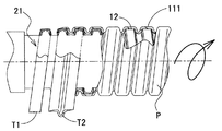
- FIG. 1 is a partial sectional view showing a pipe joint 1 according to a first embodiment of the present invention, and shows an upper half as a sectional view.
- the substantially cylindrical pipe joint 1 is a pipe joint in which a first seal material 12 and a second seal material 13 are integrated with a pipe joint main body member 11 so as to face the outer peripheral surface of a pipe to be connected.
- the pipe joint 1 is a pipe joint for connecting a corrugated pipe (not shown) whose outer peripheral surface is formed in a spiral rugged strip, and the spiral rugged strip on the outer circumference of the corrugated pipe and the inner circumference of the pipe joint.
- the spiral concavo-convex strips on the surface are matched, and the corrugated pipe is relatively rotated so as to be screwed into the pipe joint 1 and connected. And a pair of corrugated pipe can be connected by screwing in the edge part of a corrugated pipe from the both sides of the pipe joint 1, respectively.
- the pipe joint main body member 11 is a synthetic resin in which an inner peripheral surface having a spiral concavo-convex shape is formed so as to substantially match the spiral concavo-convex shape of the outer peripheral surface of the corrugated pipe to be connected. This is a substantially cylindrical member.
- the tube wall of the main body member 11 has a spiral concavo-convex shape in which the entire tube wall is alternately formed with a large-diameter portion 111 protruding radially outward and a small-diameter portion 112 recessed radially inward.
- the tube wall is formed to have a substantially uniform thickness.
- Examples of the synthetic resin for forming the main body member 11 include hard synthetic resins such as polyethylene resin, polypropylene resin, and vinyl chloride resin.
- the synthetic resin material for forming the main body member 11 may be formed of a relatively soft resin such as rubber or thermoplastic elastomer in addition to the illustrated hard synthetic resin, or may be formed by combining a hard synthetic resin and a soft synthetic resin. Also good.
- the main body member 11 can be manufactured by blow molding, injection molding, a spiral molding method described later, or the like.
- the first sealing material 12 is a sealing material made of a water-swellable non-woven fabric, and the tape-like water-swellable non-woven fabric cut into a predetermined width is spirally formed such that the side edges thereof have a predetermined distance d from each other.
- This is a spiral sealing material affixed to the inner peripheral surface of the main body member 11.
- the 1st sealing material 12 is stuck and integrated with the main body member 11 along the internal peripheral surface of the large diameter part 111 of a main body member.
- the second sealing material 13 is also a sealing material made of a water-swellable non-woven fabric, and the tape-like water-swellable non-woven fabric cut to a predetermined width is adjacent to each other in a direction generally along the tube axis direction. It is the sealing material affixed along the internal peripheral surface of the main body member 11 and the 1st sealing material 12 over the full length of a pipe joint so that it may straddle the part 12a, 12b, 12c, 12d, 12e. In the present embodiment, the second sealing material 13 is provided at one place in the circumferential direction of the main body member 11.
- the water-swellable non-woven fabric constituting the first seal material and the second seal material is a non-woven fabric in which a water-swellable resin is supported on a non-woven fabric material.
- the form of supporting the water-absorbing expandable resin can be in the form of powder, fiber, impregnation, coating, or the like.
- a water-absorbing expandable resin is a resin that has the property of absorbing moisture and swells, and exemplifies a resin containing polyacrylic acid sodium salt as a main component or a resin containing an alkene (alkylene) oxide modified compound as a main component. Can do. In particular, the latter exhibits a water-swelling property even with respect to water having a relatively high ion concentration such as seawater.
- water-swellable resins include fibrous products such as Lanseal (registered trademark, Toyobo Co., Ltd. product).
- alkene (alkylene) oxide-modified water-absorbent expandable resin include Aqua Coke (registered trademark, Sumitomo Seika Co., Ltd. product).
- the base fiber constituting the nonwoven material is not particularly limited, but is preferably a synthetic resin fiber, and synthetic resin fibers such as polyester fiber, nylon fiber, polyethylene terephthalate fiber, acrylic fiber, and polypropylene fiber can be used.
- the base fiber may be a poorly hydrophilic fiber such as polypropylene fiber or polyethylene terephthalate (PET) fiber, but is preferably a hydrophilic fiber such as acrylic fiber or nylon fiber.
- PET polyethylene terephthalate
- the basis weight of the nonwoven fabric is preferably about 100 to 500 g / square meter, and more preferably 200 to 300 g / square meter so that an appropriate elasticity can be obtained in the nonwoven fabric layer.
- the material constituting the first sealing material and the second sealing material is not limited to the water-absorbing and expansive nonwoven fabric, and other water-absorbing materials as long as the material absorbs moisture and expands and has a sealing property.
- An inflatable material can also be used.
- Other water-swellable materials include, for example, materials obtained by processing the water-swellable resin described above into a sheet or string, and these materials are laminated on other sheet-like materials made of rubber, resin, water-permeable materials, etc. The material etc. which were done can be illustrated.
- the water-absorbing and expansive material used in the present invention is preferably provided with elasticity and cushioning, and the pipe joint body member 11 It is preferable that the material has flexibility and stretchability so that it can be easily attached to the inner peripheral surface.
- Nonwoven fabrics are particularly suitable as those having such properties.
- the pipe joint 1 of 1st Embodiment of this invention can connect a corrugated pipe just by screwing the corrugated pipe
- the second seal material is disposed in a substantially tube axis direction so as to cross the entire inner peripheral surface of the main body member on which the first seal material is disposed, the seal line closed in an annular shape Are formed in a composite manner, and the reliability of water-stopping is further improved.
- the first sealing material 12 and the second sealing material 13 are disposed so as to overlap each other, but in the present embodiment, both sealing materials are made of a water-expandable material. Therefore, even when there is a step or a gap at the intersection of the first sealing material 12 and the second sealing material 13 when sticking, these water expandable materials expand when water comes in use. Steps and gaps are filled, and a good watertight seal is performed. As shown in another embodiment described later, it is obvious that this effect is exhibited if either one of the first sealing material 12 and the second sealing material 13 is made of a water-expandable material. is there.
- the seal material is pasted on the inner surface of the pipe joint.
- the part which is not worn is left.
- the first sealing material 12 or the second sealing material 13 absorbs water and expands excessively, the excessively expanded water-swellable material can wrap around the portions where these sealing materials do not exist. .
- the expanded water-absorbing expansible material enters the inside of the tube from the end of the tube, or due to the pressure of the expanded water-absorbing expansible material. It is possible to suppress or prevent the end of the tube from collapsing inward.
- the amount of water-swellable material used can be saved, resulting in cost advantages.
- the space between the adjacent side edges of the first seal material is a space from which the expanded water-absorbing and expansible material can escape, so compared with the conventional pipe joint, A water-swellable material having a higher expansion ratio can be used. That is, in the conventional pipe joint, if the expansion ratio of the water-swellable material is too large, a problem such as the water-swelling material sticking out into the pipe is likely to occur, so it is difficult to use a water-swellable material having a large expansion ratio. However, according to the present invention, since occurrence of such a problem is suppressed, a water-swellable material having a higher expansion ratio can be used, and the range of selection of the water-swellable material is widened.
- the seal material is provided only partially on the inner peripheral surface of the pipe joint, even when it is necessary to insert the pipe while compressing the seal material, when inserting (screwing) the pipe to be connected
- the operation force is relatively small.
- the clearance between the pipe joint body or the seal material and the corrugated pipe is set to be smaller than that of the conventional pipe joint, the operating force may become excessive and the joint may not be connectable. It is suppressed and the clearance can be set small. If the clearance is small, the water-stop reliability of the pipe joint can be further increased.
- the sealing material to be attached to the inner peripheral surface of the pipe joint is typically about 1/4 to 1/2 pitch of the spiral irregularities, and is used for conventional pipe joints. Compared with the cylindrical water-absorbing expandable nonwoven fabric, it has a narrow width. In conventional pipe joints, the degree of stretchability of the water-swellable material had to be increased in order to bond the cylindrical water-swellable material along the complicated inner peripheral surface shape of the pipe joint body member. In this embodiment, since the sealing material is narrow, the complexity of following the unevenness of the surface to which the sealing material is to be attached is reduced, and the degree of expansion and contraction of the sealing material is relatively low. May be. Therefore, according to the present invention, even if a water-swellable material inferior in stretchability is used, it can be bonded and integrated along the inner peripheral surface of the pipe joint main body 11, and the range of selection of the water-swellable material is expanded.
- FIG. 2 is a schematic view showing a spiral molding process for forming an indefinite length pipe joint member P in which the first sealing material 12 is spirally arranged and integrated on the inner peripheral surface of the main body member 11.
- a pipe forming shaft 21 that is rotationally driven by a known pipe forming apparatus has a predetermined cross section (in the present embodiment, the reverse) from a water-swellable material tape T1 cut to a predetermined width and a resin extrusion apparatus.
- the synthetic resin strip T2 in a semi-molten state extruded in a hat shape) is continuously wound and spirally wound, and both end portions of adjacent synthetic resin strips are overlapped with each other and integrated with each other.
- a corrugated cylindrical tube wall having a spiral ridge is formed, and the water-swellable material 12 is bonded and integrated along the inner peripheral surface of the large-diameter portion 111 of the corrugated cylindrical portion.
- An indefinite length pipe joint member P integrated in a spiral shape is obtained.
- the water-swellable material may be bonded using an adhesive or a pressure-sensitive adhesive, or may be welded using the amount of heat of the semi-molten synthetic resin strip T2.
- the pipe joint member P having an indefinite length obtained in the spiral molding process is cut into a predetermined length by a cutter or the like, and the pipe joint member Q is obtained.
- a second sealing material integration step is performed.
- a water-swellable material previously cut into a tape shape having a predetermined width is applied to the inner peripheral surface of the pipe joint member Q cut to a predetermined length over the entire length of the pipe joint member Q. Then, they are bonded and integrated along the inner peripheral surface of the pipe joint member Q so as to straddle adjacent portions of the first seal material in a direction substantially along the pipe axis direction.
- the water-swellable material of the second sealing material may be bonded using an adhesive or an adhesive material.
- the second sealing material integration step can be performed manually, but can also be mechanized.
- the manufacturing method the following effects can be obtained. That is, according to this manufacturing method, at the same time that the pipe joint main body 11 is formed, the first seal material can be spirally bonded and integrated with the inner peripheral surface thereof, and such a pipe joint member P is used. Can be manufactured continuously with indefinite length, and the production efficiency is very high. Therefore, according to this manufacturing method, the pipe joint of this invention can be manufactured efficiently.
- the 2nd sealing material 13 is followed along a pipe-axis direction.
- corrugation of the internal peripheral surface of the main body member 11 is reduced by the 1st sealing material 12, and the adhesion
- the first sealing material 12 is later spirally bonded and integrated to the inner peripheral surface of a preformed pipe joint main body member 11, and the second sealing material 13 is further connected to the pipe. It can also be manufactured by bonding and integrating along the axial direction. In that case, the first sealing material and the second sealing material can be bonded manually.
- the surface shape of the region to which the seal material is bonded in the pipe joint of the present invention is relatively simple compared to that of the conventional pipe joint because the seal material is narrow. It is also relatively easy to mechanize the bonding process as done in the work.
- the present invention is not limited to the above embodiment, and can be implemented with various modifications. Other embodiments of the present invention will be described below. However, in the following description, portions different from the above-described embodiment will be mainly described, and descriptions of the same portions will be omitted.
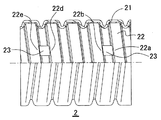
- the pipe joint 2 of the 2nd Embodiment of this invention is shown.
- the pipe joint body member 21 and the first sealing material 22 are configured in the same manner as in the first embodiment described above.
- the second sealing material 23 is made of soft rubber or In addition to being formed of a soft resin elastomer, the second sealing materials 23 and 23 are partially provided.
- the second sealing material 23 extends across adjacent portions (between 22a and 22b and between 22d and 22e in the figure) of the first sealing material arranged in a spiral shape. These are disposed so as to extend substantially in the tube axis direction, and are integrally bonded to the main body member 21.
- the end portions of the second sealing materials 23, 23 may abut against the side edges of the first sealing material 22. Further, it may ride on the side edge of the first sealing material 22.
- At least one second sealing material 23 is disposed at a portion facing the outer peripheral surface of the pipe to be connected so as to span between adjacent first sealing materials.
- a closed seal line can be completed to obtain a predetermined water stoppage.
- the second sealing material is a member having an appropriate thickness and elasticity so as to be sandwiched between the inner peripheral surface of the pipe joint main body member 21 and the outer peripheral surface of the pipe to be connected in a close contact state and perform a water stop function.
- those made of a thermoplastic elastomer or rubber can be preferably used, and those made of a thermoplastic elastomer particularly rich in flexibility can be preferably used.
- the second sealing material may be attached in such a direction as to connect the matching first sealing materials 22 (for example, between 22a and 22b).
- the second sealing material may be made of a water-swellable material.
- the pipe joint 3 of the 3rd Embodiment of this invention is shown.
- the configuration and attachment method of the pipe joint main body member 31 and the second seal material 33 are the same as those in the first embodiment, but the first seal material 32 is configured by a seal material that is not a water-expandable material.
- the first sealing material 32 is a sealing material formed of a soft thermoplastic elastomer, particularly a flexible thermoplastic elastomer such as an olefin-based thermoplastic elastomer, and is spirally formed on the inner peripheral surface of the large-diameter portion 311 of the main body member 31. Is integrated with the adhesive. As shown in FIG.
- the first seal member is a seal material in which a protrusion 322 is integrally formed at a substantially central portion of a substantially flat tape-like base 321, and the protrusion 322 is a spiral of the pipe joint body 31. Are bonded and integrated so as to be along the direction.
- the first seal is provided between the inner peripheral surface of the pipe joint main body member 31 and the outer peripheral surface of the large-diameter portion of the corrugated pipe.
- the material 32 is sandwiched and closely adhered to exhibit water-stopping properties.
- the closed seal line is completed by the spiral first seal member 32 and the second seal member 33 disposed in the portion facing the outer peripheral surface of the pipe to be connected.
- the desired water stoppage can be obtained.
- the first sealing material 32 is made of rubber or thermoplastic elastomer as in the present embodiment, it is preferable to provide the protrusion 322 on the first sealing material 32 as described above, and to provide the protrusion 322. As a result, it becomes easy to ensure an appropriate sealing property, and it is possible to reduce the operating force when screwing the corrugated tube.
- the first sealing material 32 is made of rubber or thermoplastic elastomer as in this embodiment
- a thermoplastic elastomer is extruded into a tape shape in a semi-molten state so as to be a cross section of the first seal material 32, What is necessary is just to supply to a shaping
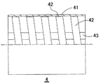
- both the first sealing material 42 and the second sealing material 43 are formed of a water-swellable non-woven fabric, the first sealing material 42 is spiral, and the second sealing material is between adjacent first sealing materials.
- the pipe joint body member 41 has a smooth cylindrical inner peripheral surface. The point is different. That is, the pipe joint 4 of this embodiment is for connecting a pipe (not shown) formed in a cylindrical shape with a smooth outer peripheral surface.
- the 1st sealing material 42 is helically formed. It is stuck.
- the present invention is not limited to a pipe joint for screwing and connecting corrugated pipes having spiral ridges, but a substantially cylindrical pipe.
- a pipe joint for inserting and connecting an end portion of a pipe inside the joint, and the above-described first seal member and second seal member are provided on the pipe joint inner peripheral surface facing the outer peripheral surface of the pipe to be connected. are widely included.
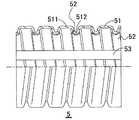
- the pipe joint 5 of the 5th Embodiment of this invention is shown.
- the configuration of the pipe joint main body member 51 and the point that both the first sealing material 52 and the second sealing material 53 are formed of a water-swellable non-woven fabric are the same as in the first embodiment.
- the position where the first sealing material 52 is disposed is different. That is, the pipe joint main body member 51 is a member formed with spiral concavo-convex ridges in which large-diameter portions 511 and small-diameter portions 512 are alternately arranged.
- the first seal member 52 has a small-diameter portion.
- the adhesive is integrated in a spiral.
- the second sealing material is bonded and integrated along the inner peripheral surface of the pipe joint body member and the inner peripheral surface of the first sealing material 52 in a substantially straight line so as to extend along the tube axis direction.
- a closed seal line is completed by the spiral first seal member 52 and the second seal material 53 disposed in the portion facing the outer peripheral surface of the pipe to be connected.
- the desired water stoppage can be obtained.
- this embodiment is an embodiment particularly suitable for adopting a manufacturing method in which the first sealing material is bonded and integrated manually.
- the second sealing material 53 is bonded after the first sealing material 52. More preferably, in the manufacture of the pipe joint 5 of the fifth embodiment, the second sealing material 53 is the second one.
- the sealing material 53 is preferably bonded along the inner peripheral surface of the pipe joint body member 51 in advance of the first sealing material, and in that case, the second sealing material is bonded to the surface to be bonded. Since the second sealing material 53 can be bonded with relatively little unevenness, the second sealing material can be easily bonded.
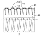
- FIG. 7 shows a pipe joint 6 according to a sixth embodiment of the present invention.
- the configuration of the pipe joint main body member 61 and the configuration and arrangement of the second seal material 63 are the same as those in the first embodiment, but the structure in which the first seal material 62 is laminated. It is a seal material. That is, the first sealing material 62 is a sealing material in which a water-absorbing / expanding layer 621 made of a tape-like water-absorbing / expanding nonwoven fabric and a tape-like thin water-permeable sheet material (for example, spunbond nonwoven fabric) are laminated as a water-permeable constraining layer 622. is there.
- the water-absorbing expansion layer 621 is spirally bonded and integrated to the inner peripheral surface of the pipe joint main body member, and the water-permeable constraining layer 622 is provided so as to cover the water-absorption expansion layer 621 and both side edges thereof are pipe fitting main bodies. It is bonded and integrated with the inner peripheral surface of the member 61.
- the pipe joint as in the present embodiment sequentially supplies the tape-shaped material constituting the water-absorbing expansion layer 621 and the tape-shaped material constituting the water-permeable constraining layer 622 to the pipe-forming shaft in the spiral molding shown in FIG. Therefore, it can manufacture efficiently.
- the water-permeable constraining layer 622 is provided so as to cover the water-absorbing / expanding layer 621, even if the water-absorbing expandable resin contained in the water-absorbing / expanding layer 621 expands, Since the water-absorbing and expanding layer 621 is prevented from being inadvertently diffused, the reliability of water-stopping can be improved even when the amount of the water-absorbing and expanding material is reduced. In addition, since it may become a channel
- FIG. 8 shows a pipe joint 7 according to a seventh embodiment of the present invention.
- the inner circumferential surface of the pipe joint body member 71 is provided with a spiral concave groove in which the first sealing material 72 is to be accommodated, and the first sealing material 72 is formed of the concave groove. It is glued and integrated in a spiral.
- the concave portion is formed so that the inner peripheral surface of the first seal member 72 does not form a step with the inner peripheral surface 71a of the pipe joint body member 71 where the first seal member 72 is not disposed. The depth of the groove and the thickness of the first seal material are determined.
- the main body member 71 as in the present embodiment can be manufactured by injection molding, or in the case of manufacturing by so-called spiral molding, a semi-molten resin strip is formed so as to have a concave groove on the inner peripheral side. It can be manufactured by extrusion.
- the present embodiment since the first sealing material and the inner peripheral surface of the main body member do not cause a step, the gap between the outer peripheral surface of the pipe and the inner peripheral surface of the main body member or the first sealing material. Even if the clearance of the pipe is reduced, the connection operation of the pipe connection is less likely to be hindered, so the clearance between the pipe and the pipe joint can be reduced. And if clearance can be made small, it is advantageous at points, such as a water stop and the connection strength of a pipe joint. Further, when a water-swellable material having relatively low elasticity is used for the first sealing material, the present embodiment can be effectively employed. Further, in the present embodiment, since the first sealing material and the inner peripheral surface of the main body member are configured not to cause a step, the second sealing material 73 can be easily attached, and the pipe joint is efficiently manufactured. be able to.
- the pipe joint in which the second sealing material is disposed at one place in the circumferential direction has been described.
- the second sealing material is disposed at two places or more in the circumferential direction. May be. If the second sealing material is disposed at two or more locations, the reliability of the seal can be further increased.
- the 1st sealing material does not necessarily need to be provided over the whole internal peripheral surface.
- the first seal material and the second seal material may be disposed at both ends of the pipe joint in the tube axis direction, and the seal material may not be disposed at the center of the pipe joint in the tube axis direction. .
- connection structure and a seal structure for example, a known structure using a rubber packing, a gasket, an O-ring, a lip seal, a metal band, grease, etc. may be adopted.
- a pipe joint that has a sufficient water-stopping property and can prevent the water-swellable material from protruding into the pipe or crush the end of the pipe even during long-term use, and is easy to manufacture. it can. Moreover, according to the pipe joint manufacturing method of this invention, such a pipe joint can be manufactured efficiently.
- the obtained pipe joint can be preferably used, for example, as a pipe joint for pipes that require water-stopping, such as underground buried pipes and cable sheath pipes, and has high industrial utility value.
Landscapes
- Engineering & Computer Science (AREA)
- General Engineering & Computer Science (AREA)
- Mechanical Engineering (AREA)
- Joints That Cut Off Fluids, And Hose Joints (AREA)
- Laying Of Electric Cables Or Lines Outside (AREA)
Priority Applications (1)
| Application Number | Priority Date | Filing Date | Title |
|---|---|---|---|
| EA201170664A EA019022B1 (ru) | 2008-11-08 | 2009-10-29 | Трубное соединение и способ его изготовления |
Applications Claiming Priority (2)
| Application Number | Priority Date | Filing Date | Title |
|---|---|---|---|
| JP2008287223A JP4709262B2 (ja) | 2008-11-08 | 2008-11-08 | 管継手用管体の製造方法、管継手の製造方法、管継ぎ手 |
| JP2008-287223 | 2008-11-08 |
Publications (1)
| Publication Number | Publication Date |
|---|---|
| WO2010052858A1 true WO2010052858A1 (ja) | 2010-05-14 |
Family
ID=42152671
Family Applications (1)
| Application Number | Title | Priority Date | Filing Date |
|---|---|---|---|
| PCT/JP2009/005716 Ceased WO2010052858A1 (ja) | 2008-11-08 | 2009-10-29 | 管継ぎ手およびその製造方法 |
Country Status (3)
| Country | Link |
|---|---|
| JP (1) | JP4709262B2 (enExample) |
| EA (1) | EA019022B1 (enExample) |
| WO (1) | WO2010052858A1 (enExample) |
Families Citing this family (3)
| Publication number | Priority date | Publication date | Assignee | Title |
|---|---|---|---|---|
| JP5550575B2 (ja) * | 2011-01-27 | 2014-07-16 | タイガースポリマー株式会社 | 管継手およびその製造方法 |
| JP5606945B2 (ja) * | 2011-02-02 | 2014-10-15 | タイガースポリマー株式会社 | 管継手およびその製造方法 |
| JP5762817B2 (ja) * | 2011-05-10 | 2015-08-12 | タイガースポリマー株式会社 | 管継手 |
Citations (4)
| Publication number | Priority date | Publication date | Assignee | Title |
|---|---|---|---|---|
| JPH0610689U (ja) * | 1991-10-28 | 1994-02-10 | フジモリ産業株式会社 | 空調用ダクト |
| JP2001330184A (ja) * | 2000-05-20 | 2001-11-30 | Hidehiko Takehara | 通液管用継手及びこれに使用されるリングパッキン |
| JP2003194266A (ja) * | 2001-12-25 | 2003-07-09 | Denki Kagaku Kogyo Kk | スパイラル波付管及びその接続方法 |
| JP2004336953A (ja) * | 2003-05-12 | 2004-11-25 | Furukawa Electric Co Ltd:The | 管継手 |
Family Cites Families (2)
| Publication number | Priority date | Publication date | Assignee | Title |
|---|---|---|---|---|
| ATE168180T1 (de) * | 1992-12-08 | 1998-07-15 | Royal Ordnance Plc | Rohrverbindung |
| JP3647857B1 (ja) * | 2004-07-12 | 2005-05-18 | 共和ゴム株式会社 | 管継手の製造方法 |
-
2008
- 2008-11-08 JP JP2008287223A patent/JP4709262B2/ja active Active
-
2009
- 2009-10-29 WO PCT/JP2009/005716 patent/WO2010052858A1/ja not_active Ceased
- 2009-10-29 EA EA201170664A patent/EA019022B1/ru not_active IP Right Cessation
Patent Citations (4)
| Publication number | Priority date | Publication date | Assignee | Title |
|---|---|---|---|---|
| JPH0610689U (ja) * | 1991-10-28 | 1994-02-10 | フジモリ産業株式会社 | 空調用ダクト |
| JP2001330184A (ja) * | 2000-05-20 | 2001-11-30 | Hidehiko Takehara | 通液管用継手及びこれに使用されるリングパッキン |
| JP2003194266A (ja) * | 2001-12-25 | 2003-07-09 | Denki Kagaku Kogyo Kk | スパイラル波付管及びその接続方法 |
| JP2004336953A (ja) * | 2003-05-12 | 2004-11-25 | Furukawa Electric Co Ltd:The | 管継手 |
Also Published As
| Publication number | Publication date |
|---|---|
| EA019022B1 (ru) | 2013-12-30 |
| EA201170664A1 (ru) | 2012-02-28 |
| JP2010112510A (ja) | 2010-05-20 |
| JP4709262B2 (ja) | 2011-06-22 |
Similar Documents
| Publication | Publication Date | Title |
|---|---|---|
| US8646489B2 (en) | Connection structure of wave-shaped synthetic resin pipes, wave-shaped synthetic resin pipes used for the connection structure, and manufacturing method thereof | |
| JP6038719B2 (ja) | 補強材入り帯状部材及びその製造方法 | |
| JP4709262B2 (ja) | 管継手用管体の製造方法、管継手の製造方法、管継ぎ手 | |
| JP5204251B2 (ja) | 管継手 | |
| JP5431977B2 (ja) | 管継ぎ手およびその製造方法 | |
| JP5606945B2 (ja) | 管継手およびその製造方法 | |
| JP5363251B2 (ja) | 管継手および管の接続構造 | |
| JP2005121186A (ja) | 漏水防止用パッキング | |
| JP5762817B2 (ja) | 管継手 | |
| JP6134252B2 (ja) | 管継手およびその製造方法 | |
| JP5431844B2 (ja) | 管継手の製造方法 | |
| JP5897338B2 (ja) | 合成樹脂製可撓管 | |
| JP5550575B2 (ja) | 管継手およびその製造方法 | |
| JP2010255671A (ja) | 合成樹脂製可撓管 | |
| JP4357831B2 (ja) | 可撓性を有する管継手用合成樹脂製耐圧管体 | |
| CN220102337U (zh) | 一种高强度缠绕管 | |
| JP2004332895A (ja) | 管継手 | |
| JPH089510Y2 (ja) | 螺旋波形管用の管継手 | |
| JP2009293763A (ja) | 管継ぎ手及び管の接続方法 | |
| JPH05245939A (ja) | コルゲート管の接続方法およびその継手部材 | |
| JP2009197850A (ja) | 管継ぎ手及び管の接続方法 | |
| JP3515163B2 (ja) | 管継手 | |
| JP4413554B2 (ja) | 配管ボックスにおける管体接続構造 | |
| JP2003120870A (ja) | 螺旋状山形リブを持つ大型樹脂管のシール方法 | |
| CN201843181U (zh) | 双卡槽双增强钢带型钢塑复合结构壁排水管 |
Legal Events
| Date | Code | Title | Description |
|---|---|---|---|
| 121 | Ep: the epo has been informed by wipo that ep was designated in this application |
Ref document number: 09824559 Country of ref document: EP Kind code of ref document: A1 |
|
| NENP | Non-entry into the national phase |
Ref country code: DE |
|
| WWE | Wipo information: entry into national phase |
Ref document number: 201170664 Country of ref document: EA |
|
| 122 | Ep: pct application non-entry in european phase |
Ref document number: 09824559 Country of ref document: EP Kind code of ref document: A1 |