WO2010050236A1 - コークス炉におけるコークス押出しの際に発生する負荷の推定方法 - Google Patents
コークス炉におけるコークス押出しの際に発生する負荷の推定方法 Download PDFInfo
- Publication number
- WO2010050236A1 WO2010050236A1 PCT/JP2009/005795 JP2009005795W WO2010050236A1 WO 2010050236 A1 WO2010050236 A1 WO 2010050236A1 JP 2009005795 W JP2009005795 W JP 2009005795W WO 2010050236 A1 WO2010050236 A1 WO 2010050236A1
- Authority
- WO
- WIPO (PCT)
- Prior art keywords
- coke
- extrusion
- load
- furnace
- cake
- Prior art date
- Legal status (The legal status is an assumption and is not a legal conclusion. Google has not performed a legal analysis and makes no representation as to the accuracy of the status listed.)
- Ceased
Links
Images





Classifications
-
- C—CHEMISTRY; METALLURGY
- C10—PETROLEUM, GAS OR COKE INDUSTRIES; TECHNICAL GASES CONTAINING CARBON MONOXIDE; FUELS; LUBRICANTS; PEAT
- C10B—DESTRUCTIVE DISTILLATION OF CARBONACEOUS MATERIALS FOR PRODUCTION OF GAS, COKE, TAR, OR SIMILAR MATERIALS
- C10B45/00—Other details
-
- C—CHEMISTRY; METALLURGY
- C10—PETROLEUM, GAS OR COKE INDUSTRIES; TECHNICAL GASES CONTAINING CARBON MONOXIDE; FUELS; LUBRICANTS; PEAT
- C10B—DESTRUCTIVE DISTILLATION OF CARBONACEOUS MATERIALS FOR PRODUCTION OF GAS, COKE, TAR, OR SIMILAR MATERIALS
- C10B33/00—Discharging devices; Coke guides
-
- C—CHEMISTRY; METALLURGY
- C10—PETROLEUM, GAS OR COKE INDUSTRIES; TECHNICAL GASES CONTAINING CARBON MONOXIDE; FUELS; LUBRICANTS; PEAT
- C10B—DESTRUCTIVE DISTILLATION OF CARBONACEOUS MATERIALS FOR PRODUCTION OF GAS, COKE, TAR, OR SIMILAR MATERIALS
- C10B33/00—Discharging devices; Coke guides
- C10B33/08—Pushers, e.g. rams
-
- G—PHYSICS
- G01—MEASURING; TESTING
- G01L—MEASURING FORCE, STRESS, TORQUE, WORK, MECHANICAL POWER, MECHANICAL EFFICIENCY, OR FLUID PRESSURE
- G01L1/00—Measuring force or stress, in general
Definitions
- the present invention for example, at the time of coke extrusion in a horizontal chamber type coke oven, particularly in the case where there are protrusions on the furnace wall of the carbonization chamber, takes into account the properties of the coke cake determined by the type of charging coal and dry distillation conditions. It is related with the method of estimating the load which generate
- This application claims priority based on Japanese Patent Application No. 2008-279889 filed in Japan on October 30, 2008, the contents of which are incorporated herein by reference.
- the force required to extrude the coke cake from the carbonization chamber of the coke oven is determined by the resistance when moving the coke cake.
- the main factor of “factors caused by the furnace body” is the properties of the furnace wall. Specifically, there are unevenness of the furnace wall brick, roughness of the brick surface, coefficient of friction between the furnace wall and the coke cake, furnace wall strength (displacement of the furnace wall during extrusion), and the like. Of these, the effect of the unevenness of the furnace wall brick is considered to be the largest.
- coke ovens have deteriorated, and in the carbonization chamber of coke ovens, as described above, carbon adheres to the furnace walls and protrusions are often formed. In the portion where the carbon protrusion is formed, the furnace width (distance between furnace walls) is narrowed accordingly (furnace width narrow portion).
- the coke cake When the coke cake passes through the narrow portion of the furnace, it receives a reaction force from the slope of the protrusion on the extruder side. Further, since the coke cake is allowed to pass through a portion narrower than the original carbonization chamber width, naturally, an extra force is required than usual. As described above, when the coke cake passes through the protrusion, the resistance when the coke cake is pushed out increases.
- the extrusion pressure of the coke cake acts as a pressure that pushes the furnace wall by the side pressure conversion rate determined by the gap (clearance) between the coke lump and the furnace wall. If extra resistance is required, such as the reaction force received from the slope of the projection or the force required to pass through the narrow furnace width, extra extrusion force is required to overcome these forces. Become. Therefore, a load (pressure) larger than usual acts on the furnace wall according to the degree of the resistance force.
- factors attributed to the characteristics of the coke cake include the strength of the coke mass, the amount of horizontal burn-out (rate), and the amount of voids (rate) in the coke cake.
- the coal softened and melted layers meet at the center in the furnace width direction and then contract in the furnace width direction, resulting in a horizontal burnout in which the volume decreases in the horizontal direction.
- the horizontal burning of this coke is the amount of voids formed in the center of the coke oven width direction and the amount of voids formed between the furnace wall and the coke lump (the sum of these void amounts is referred to as “ It is closely related to “the void volume”.
- Patent Documents 2 and 3 disclose techniques for adjusting operation conditions such as the carbonization time so that the value does not fall below a predetermined value.
- Patent Document 1 It is disclosed in Patent Document 1 that if the coke cake is in the same carbonized state, the extrusion load is well expressed by a resistance index defined from the situation (shape, location, etc.) of the protrusion on the furnace wall surface. .
- a resistance index defined from the situation (shape, location, etc.) of the protrusion on the furnace wall surface.
- the carbonization conditions of coal may differ with each coke oven.
- the combustion chamber has a configuration in which a plurality of gas supply ports and air supply ports are arranged side by side in the coke extrusion direction. For this reason, there is a possibility that the dry distillation conditions of coal differ depending on the deterioration state of each gas supply port or air supply port. That is, even in one coke oven, the coal carbonization conditions may be different.
- Patent Document 3 describes that the thickness of carbon attached to the furnace wall is taken into account, but the protrusion of the furnace wall due to attached carbon is not a problem.
- the influence of the factor on the furnace side on the coke extrusion force is related by the resistance index described above, but no clear index is disclosed when the factor on the coke cake side is also involved at the same time. .
- the factors on the coke cake side may fluctuate. Therefore, even if the extrusion force is estimated using the resistance index described in Patent Document 1, the estimated accuracy May cause problems. Conventionally, attention is paid to the gap between the furnace wall and the coke lump, but the actual gap amount is about several millimeters, whereas the gap amount in the center of the coke in the furnace width direction is several tens of millimeters. mm.
- the object of the present invention is to provide an index having a good correspondence with the extrusion force under conditions including the influence of both the properties of the coke cake and the factors on the furnace side determined by the type of coal charge and the carbonization conditions, and coke extrusion. This is to further improve the load estimation accuracy.
- the extrusion force when the coke cake passes through the narrow part of the furnace where the width of the furnace is narrowed by the amount of the protrusion formed is the thickness of the protrusion and the total amount of voids in the furnace width direction (in the furnace width direction). This is considered to be governed by the relationship between the total void volume) and the furnace wall distance. Therefore, as a result of investigating the relationship between the thickness of the protrusion with respect to the extrusion load, the total void amount in the furnace width direction, and the distance between the furnace walls, the coke cake passed through the narrow part of the furnace width. It has been found that the extrusion load can be expressed by a specific index.
- the gist of the present invention based on such knowledge is as follows.
- the method for estimating the load generated during coke extrusion in the coke oven according to the present invention is a method in which a narrow furnace width portion in which the distance between the furnace walls is narrowed by the protrusions present on the furnace wall of the coke oven carbonization chamber.
- the extrusion load when the coke cake passes is evaluated using the index Qn defined by the following formula (1) with the distance L between the furnace walls, the thickness h of the projections, and the total void amount w in the furnace width direction as parameters.
- the total void amount w is a void amount obtained by combining the void amount between the furnace wall on the left and right of the coke cake extrusion direction and the coke cake and the void amount in the center of the coke cake.
- Qn (hw) / L (1) (2)
- the extrusion load under the condition of the total void amount w in the width direction was measured a plurality of times while exchanging the protrusions, and the extrusion measured with the Qn calculated using the equation (1) according to claim 1.
- a correlation X with the load is obtained in advance. And, from the thickness h 1 of the projection of the furnace wall of the coke oven carbonization chamber, the total void amount w 1 in the furnace width direction obtained from the type of charging coal and dry distillation conditions, and the distance L 1 between the furnace walls, It is preferable to calculate the index Qn 1 related to the coke oven carbonization chamber using the equation (1) described in the above, and to determine the extrusion load of the coke oven carbonization chamber based on the correlation X and the Qn 1 . (3) In the case of (2) above, it is preferable to calculate the thickness h 1 of the protrusion by integrating the profile information of the furnace wall.
- the factor on the furnace wall side which is the factor related to the coke cake extrusion load, and the factor on the coke cake side are simultaneously considered. For this reason, it is possible to accurately estimate the coke extrusion force and the pressing force (furnace wall side pressure) acting on the furnace wall corresponding to the state of the furnace wall, the type of charging coal, and the carbonization conditions. For this reason, the operating conditions of the coke oven and the properties of the charged coal can be managed so that the furnace wall side pressure estimated based on the coke extrusion load does not exceed the pressure limit of the furnace wall. As a result, troubles such as furnace wall piercing can be prevented.
- FIG. 5A It is a side view of the coke extrusion load measurement test apparatus shown in FIG. 5A. It is a figure which shows an example of the shape of the projection part used for the coke extrusion load measurement test apparatus shown in FIG. 5A.
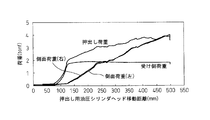
- FIG. 6 is a diagram showing an example of measurement results of an extrusion test using the coke extrusion load measurement test apparatus shown in FIGS. 5A to 5C. It is a figure for demonstrating the space
- the protrusion 9 passes through the protrusion 9.
- the force required for the passage includes the thickness of the protrusion 9 in the furnace width direction (thickness h of the protrusion), the total amount of voids in the furnace width direction (total void amount w in the furnace width direction), and the distance between the furnace walls It is thought that it is dominated by L.
- the present inventors have intensively investigated the relationship between the protrusion thickness h and the total void amount w in the furnace width direction with respect to the extrusion load by using a coke extrusion measurement test, which will be described later. .
- the force (extrusion force) required for the coke cake to pass through the narrow furnace width portion where the distance between the furnace walls is narrowed by the protrusions uses the index Qn defined by the following equation (1). I found out that it can be organized.
- Qn (hw) / L (1)
- the total void amount w in the furnace width direction is a value determined by the type of charging coal, dry distillation conditions, and the like, as will be described later.
- the total void amount w in the furnace width direction is the amount of voids 23 between the furnace wall 26 of the carbonization chamber and the coke lump 25 (the total amount of voids on both sides of the carbonization chamber) and the coke cake. It is the total amount with the amount of the gap 24 in the center in the furnace width direction.
- h is the thickness of the projection 9 (furnace width direction)
- L is the distance between the furnace walls 26 (furnace width) of the carbonization chamber.
- (hw) is divided by the furnace wall distance L.
- the furnace width of the coking chamber is from the extruder side (PusherushSide, PS) to the coke guide wheel side (Coke Side, CS). This is because the influence of the position of the coking chamber in the furnace length direction can be reflected. Moreover, since the width
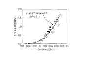
- FIG. 1 shows the relationship between the index Qn and the force required for the passage of the protrusion 9 obtained in this test (the value obtained by subtracting the reaction force from the coke pressing force, that is, the force required for getting over the protrusion). Moreover, the relationship between the pressure (terrace surface pressing) which acts on the terrace surface 22 of the protrusion part 9 and the index
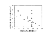
- FIG. 4 shows the relationship between the force required for overcoming the protrusion and the total void amount w in the furnace width direction, but a good correspondence as shown in FIG. 1 cannot be obtained. From this, the effectiveness of obtaining the correlation in consideration of the thickness h of the protrusion and the distance L between the furnace walls with respect to the total void amount w in the furnace width direction was confirmed.
- the extrusion load (force necessary to overcome the protrusion, terrace surface pressure, and lateral pressure conversion rate) is a factor on the coke cake side that is determined by factors on the furnace body side, type of charging coal, dry distillation conditions, etc. It was shown that it can be estimated with high accuracy by an expression using the index Qn determined in consideration of the above.
- the formation position and the thickness h of the protrusions are measured with a laser distance meter with respect to the furnace wall surface of the carbonization chamber, as described in Patent Document 4, for example. It can be obtained by moving and actually measuring. With the recent aging of coke ovens, it is becoming increasingly important to understand the state of the wall of the coking chamber. Therefore, it is important to measure the profile of the furnace wall in the height direction and the furnace length direction in the carbonization chamber, and to investigate and measure the state of the furnace wall brick and the position and shape of the unevenness formed on the furnace wall. Sex is increasing. Various devices for performing such investigations and measurements have been proposed in addition to Patent Document 4 described above. In the present invention, when measuring the formation position of the protrusion, the thickness h of the protrusion, and the shape thereof, such known means can be appropriately used.
- the total void amount w in the furnace width direction can be obtained, for example, as follows.
- the shrinkage rate of coke during dry distillation varies depending on the operating conditions such as brands, blending ratio, and dry distillation time of a plurality of raw coals to be blended.
- the combustion temperature of the combustion chamber has an in-row temperature distribution so that heating to coal is constant. Since the coke shrinkage rate changes depending on the temperature, the coke shrinkage rate during dry distillation may change depending on the position of the coke oven in the coke extrusion direction.
- a dry distillation test is performed using a test furnace such as a small electric furnace (for example, the size of the carbonization chamber is 1050 mm long ⁇ 900 mm high ⁇ 450 mm wide).
- the relationship between the carbonization time at various furnace temperatures and the amount of quenching is obtained in advance under various coal charging conditions. From these relationships obtained in this test, the amount of coke burn-out (shrinkage rate) in the furnace width direction in actual operation can be obtained.
- Coke shrinkage begins after the softened and molten layer disappears in the coke oven. At this time, the coke contracts toward the contraction center in the coke. Therefore, the reduction in the volume of the coke due to the shrinkage is distributed between the reduction in the volume due to the shrinkage of the coke at the center of the carbonization chamber and the reduction in the volume due to the shrinkage of the coke on the furnace wall side.
- the shrinkage rate (shrinkage coefficient) of coke is mainly determined from the volatile matter and temperature of coal. For example, C. Meyer, D. Habermehl and O.
- the shrinkage rate of each part of the coke layer can be obtained by giving the volatile content and the temperature.
- the temperature of each part of the coke layer may be directly measured using a sheath thermocouple or the like. For example, it is described in Tashiro et al., Fuji Steel Technical Report, 17 (1968), page 353, etc. It can be estimated by calculating a one-dimensional heat conduction model using a known method.
- any position in the coking chamber furnace width direction is the shrinkage center.
- the coke shrinkage on the furnace wall side is calculated.
- the average value of the coke shrinkage on the furnace wall side obtained at each shrinkage center position is defined as the coke shrinkage on the furnace wall side.
- the progress of dry distillation in a coke oven is considered to be symmetrical with respect to the center in the furnace width direction in the carbonization chamber because the combustion chambers are arranged on both sides of the carbonization chamber.
- one half of one side of the carbonization chamber is divided into 10 equal parts in the furnace width direction, and 11 points including the 10 divided positions and both ends of the carbonization chamber are on the furnace wall side when the respective positions are the contraction centers.
- the coke shrinkage amount on the furnace wall side at these 11 points the coke shrinkage amount on the furnace wall side can be obtained, and the void amount between the furnace wall and the coke lump can be obtained.
- the void amount at the center in the furnace width direction can be obtained by calculating the average shrinkage of the coke at the center in the furnace width direction.
- the coke extrusion force and the load applied to the side wall surface when protrusions having various thicknesses h are present on the side wall surface are determined between the side wall and the coke mass.
- a method for obtaining the void amount and the void amount at the center in the width direction under various conditions will be described.
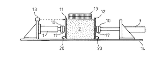
- a pair of side support bodies 7 and 7 (on the left and right with respect to the coke cake extrusion direction) are opposed to each other on the base 14 at a certain interval. Installed.
- a pair of supports 15 and 16 are disposed opposite to each other at a predetermined interval before and after the coke cake extrusion direction.
- the extrusion hydraulic cylinder 1 is attached to one support 15, and the reaction force addition hydraulic cylinder 3 is attached to the other support 16.
- a pair of side panels 5 and 5 serving as left and right side walls are disposed between the left and right side supports 7 and 7, respectively.
- a front panel 11 and a rear panel 12 (front and rear panels 11, 12) serving as movable walls are disposed between the opposing extrusion hydraulic cylinder 1 and the reaction force addition hydraulic cylinder 3, respectively.
- the pair of side panels 5 and 5 and the front and rear panels 11 and 12 form an extrusion space for the test coke cake 2.
- Rollers 20 are attached to the lower ends of the front and rear panels 11 and 12, respectively, so that they can move smoothly on the base 14. Therefore, when measuring the extrusion load and the receiving load described later, the friction between the front and rear panels 11 and 12 and the base 14 is reduced, and the accuracy of the measurement result obtained is improved.
- the pushing hydraulic cylinder 1 transmits a pressing force to the front panel 11 by a cylinder head 10 at the tip of the rod.
- the reaction force adding hydraulic cylinder 3 transmits a certain reaction force against the pressing force to the rear panel 12.
- a load cell (load converter) 17 is installed between the cylinder head 10 of the extrusion hydraulic cylinder 1 and the front panel 11.
- a load cell (load converter) 17 is installed between the cylinder head 10 and the rear panel 12 of the reaction force applying hydraulic cylinder 3 as load detecting means.
- the load cells 17 and 17 detect the pushing force of the pushing hydraulic cylinder 1 and the force received by the reaction force adding hydraulic cylinder 3.
- an air gap (reference numeral 23 in FIG. 7) exists between the furnace wall surface and the coke lump.
- the side panels 5 and 5 have intermediate movable walls 6 and 6 held by the side panel support hydraulic cylinders 4 and 4 so that the side panels 5 and 5 can be displaced in a direction perpendicular to the coke cake extrusion direction. Installed.
- the distance between the side panels 5 and 5 and the coke cake 2 in the direction perpendicular to the direction in which the coke cake 2 is extruded is measured by the position detectors 8 and 8 provided before and after the coke cake 2 in the direction in which the coke cake 2 is extruded.
- the intermediate movable walls 6 and 6 can be appropriately adjusted by moving the side panel supporting hydraulic cylinders 4 and 4.
- a plurality of load cells 18 and 18 for measuring the load applied to the side panels 5 and 5 are installed.
- the load (receiving force) received by the left and right side panels 5 and 5 is detected as the total value of the values measured by the respective load cells 18.
- the side panels 5 and 5 may move in the coke extrusion direction together with the coke cake 2 during coke extrusion.
- a movement restricting device such as a stopper or a linear motion guide may be attached to both ends of the side panels 5 and 5 in the coke pushing direction.
- the protrusion part as shown in FIG. 9 is attached by fixing means such as bolts.
- the shape of the protruding portion 9 is set in accordance with the shape of the actual protruding portion of the coke oven obtained by the above method.
- a trapezoidal projection 9 having a wedge-shaped slope in part is shown in FIG. 5C.
- the protrusion 9 is composed of a terrace surface 22 parallel to the extrusion direction and an inclined surface 21 connected thereto.
- the trapezoidal protrusion 9 having a wedge-shaped inclined surface 21 is shown as an example.
- an actual coke oven such as an inclined surface having a droplet-like curve or a wavy inclined surface is used.
- the weight 19 as a load is loaded on the upper part of the coke cake 2 so that the measurement can be performed in a state where the assumed position of the protrusion 9 in the height direction of the carbonization chamber is changed.
- the weight 19 loaded on the coke cake for example, a steel plate can be used.
- the magnitude of the load can be changed by changing the thickness of the steel plates or the number of sheets to be stacked.
- a position detector 13 such as a laser distance meter is attached to the extrusion hydraulic cylinder support 15 provided on the base 14.
- the position detector 13 can continuously measure the moving distance of the front panel 11 during coke extrusion.
- a test coke having a predetermined size obtained by carbonization in a small electric carbonization furnace or the like, for example.
- the cake 2 is arranged in a space surrounded by the side panels 5 and 5 and the front and rear panels 11 and 12 of the apparatus.
- a projection 9 having predetermined conditions (such as a shape detected by an actual coke oven) is attached to the side panel 5 on one side in advance as shown in FIG. 5A.
- the amount of voids in the central part of the coke cake 2 is measured.
- the position detectors 8 and 8 provided on the front and back sides of the side supports 7 and 7 indicate the amount of gap between the coke lump constituting the coke cake 2 arranged on the base 14 and the side panels 5 and 5. Is adjusted to a predetermined value by moving the intermediate movable walls 6, 6. Further, on the upper part of the coke cake 2, a weight 19 having a weight that assumes the position of the protrusion 9 in the furnace height direction of the actual coke oven carbonization chamber is loaded.
- the extrusion hydraulic cylinder 1 is operated to apply an extrusion force to the coke cake 2, and the coke cake 2 starts to be extruded while a certain reaction force is applied by the reaction force addition hydraulic cylinder 3.
- the coke cake 2 moves in the direction of the reaction force application hydraulic cylinder 3 by the force of (extrusion force-reaction force), moves (climbs up) the slope 21 of the protrusion 9, and finally It moves so as to ride on the terrace surface 22 of the protrusion 9.
- the load cells 17 and 18 continuously measure the extrusion force, the reaction force, and the force applied to the left and right side panels 5, 5.
- the hydraulic device of the hydraulic cylinder 3 is controlled so that the reaction force by the reaction force addition hydraulic cylinder 3 is constant.
- the assumed position in the furnace length direction of the coke cake 2 in the actual coke oven is changed.
- the load applied to the furnace wall at an arbitrary position in the furnace length direction can be evaluated.
- the assumed position of the coke cake 2 in the actual coke oven in the furnace height direction can be changed. The load applied to the furnace wall at the position can be evaluated.
- the extrusion load and the receiving side load increase, and the receiving side load reaches the set value (about 1.9 tonf) of the reaction force adding hydraulic cylinder 3.
- the load on the receiving side was maintained at a substantially constant value.
- Such a coke extrusion test was carried out by changing the thickness h of the protrusion, the amount of void between the side wall (side panel) and the coke lump, and the amount of void in the center of the coke cake, and the extrusion load and side surface in each case. The load was measured. As a result, FIG. 1 to FIG. 4 were obtained.
- ⁇ indicates that the initial value of the gap between the side wall and the coke mass is 5 mm (total on both sides), the initial value of the gap in the center of the coke cake is 14 mm, and the thickness h of the protrusion is This is a result when the test is performed while changing in the range of 0 to 50 mm.
- ⁇ is the result when the test was performed with the thickness h of the protrusions being constant (30 mm) and changing the total void amount w in the width direction (between the side panels).
- ⁇ When the thickness h of the protrusion is constant (30 mm), the initial value of the gap between the side wall and the coke mass is 0 mm (total on both sides), and the amount of void at the center of the coke cake is changed. Is the result of ⁇ shows the result when the thickness h of the protrusion is constant (30 mm), the initial value of the gap amount at the center of the coke cake is 14 mm, and the gap between the side wall and the coke mass is changed. .
- the above coke extrusion load measurement test is systematically performed by changing the reaction force by the reaction force addition (receiving side) cylinder 3 and the load amount of the weight 19 loaded on the upper portion of the coke cake. For example, it is possible to obtain the relationship between the index Qn corresponding to the protrusions existing under various conditions, the extrusion force, the terrace surface pressing, and the lateral pressure conversion rate.
- the above-mentioned extrusion load measurement test showed the result at the time of performing cold, the same result is obtained even if it is a case where it is performed warm.
- Patent Document 4 describes the position of the protrusion on the wall surface of the coking chamber of the actual coke oven, the thickness h 1 thereof, and the distance L 1 between the furnace walls where the protrusion is located. Find it by such means. Furthermore, the total void amount w 1 in the coking chamber furnace width direction at the place where the protrusion is present is estimated by a method as described in Patent Document 3, for example.
- an index Qn 1 is calculated. Then, previously obtained indices Qn and extrusion force, based on the relationship between the terrace surface pressing, and lateral pressure conversion, pushing force from the calculated Qn 1 for every projection existing on the carbonization chamber furnace wall, terrace surfaces pressing And the lateral pressure conversion rate.
- the Qn 1 can be estimated accurately extrusion force than conventional, terrace surfaces pressing, and the lateral pressure conversion .
- the force required to extrude the coke cake from the carbonization chamber of the actual coke oven is estimated.
- the number of protrusions affecting the extrusion of the coke cake varies depending on the progress of the coke cake extrusion.
- the force required for extrusion of a coke cake can be estimated about each protrusion part, even in such a case, the extrusion force of a coke cake required can be estimated accurately.
- the present invention it is possible to accurately estimate and evaluate the extrusion load relating to each protrusion as described above, and therefore, it is possible to calculate the extrusion force required to get over each protrusion. It has become possible. Thereby, the various effects mentioned later are acquired.
- the index Qn is calculated in consideration of the total void amount in the furnace width direction of the coke cake and the thickness of the protrusion. Therefore, the gas supply port and air supply port of the combustion chamber are blocked due to aging deterioration of the combustion chamber, damage to the furnace wall, etc., the supply amount of these gases and air changes, and the temperature distribution in the column changes. Therefore, even in a coke oven in which variation in the carbonization of coal occurs, the required coke cake extrusion force can be accurately estimated.
- the extrusion force required to extrude the coke cake from the coke oven of the coke oven estimated by the above methods exceeds the capacity of the extruder (or operational control value)
- the estimated value of the pressure acting on the terrace surface of the projection part existing on the wall surface exceeds the pressure-resistant rigidity limit of the furnace wall with this projection part, for example, the shrinkage of the coke cake in the furnace width direction
- the total gap amount is estimated again under the condition that the carbonization time is extended.
- the value of extrusion force and terrace surface pressure is estimated, and the estimated value of extrusion force required to extrude the coke cake is less than the capacity of the extruder (or operational control value).
- the operating condition of a coke oven is managed so that the estimated value of a terrace surface pressing may be less than the pressure
- the blending condition of the charging coal is quickly changed in advance, and the amount of void between the furnace wall and the coke lump and the coke cake in the center in the furnace width direction are changed. It is possible to adjust and manage so as to increase the amount of voids.
- the order of priority for carrying out repair work Therefore, it is possible to promptly make a decision such as accurately determining the repair efficiency and improve the repair efficiency.
- the force required for coke extrusion can be estimated as described above, whether or not coke extrusion is possible can be determined in advance. Thus, troubles such as coke stuffing are reduced.
- the coke extrusion force, the terrace surface pressure, and the lateral pressure conversion rate can be estimated with high accuracy, and the operation is performed based on the knowledge.
- operational troubles such as coke clogging, furnace wall brick breakage, and furnace wall damage can be prevented. Therefore, in addition to extending the life of the furnace body, the production of coke is increased by reducing the occurrence of operational troubles.
- the method for estimating the coke extrusion load in the coke oven of the present invention can prevent operational troubles such as coke clogging, furnace wall brick breakage, and furnace wall damage.
- operational troubles such as coke clogging, furnace wall brick breakage, and furnace wall damage.
- there are also effects such as an increase in coke production and a reduction in work load due to a reduction in the occurrence of operational troubles.
Landscapes
- Chemical & Material Sciences (AREA)
- Engineering & Computer Science (AREA)
- Materials Engineering (AREA)
- Oil, Petroleum & Natural Gas (AREA)
- Organic Chemistry (AREA)
- Physics & Mathematics (AREA)
- General Physics & Mathematics (AREA)
- Coke Industry (AREA)
Abstract
Description
本願は、2008年10月30日に、日本国に出願された特願2008-279889号に基づき優先権を主張し、その内容をここに援用する。
また、建設されて30年以上が経過して炉体の老朽化が進展し、炉壁の剛性が低下したコークス炉も増えている。このようなコークス炉では、コークス炉炭化室の炉壁面に変形や凹凸が生じている。これらの変形や凹凸の生じている箇所をコークスケーキが通過する際には、コークス押出し抵抗が増加し、炉壁にかかる荷重が上昇する。その結果、このコークス炉では、炉壁煉瓦の破孔や炉壁損壊等のトラブルが発生する虞が高くなっている。
このうち、炉壁煉瓦の凹凸の影響が最も大きいと考えられる。特に、近年ではコークス炉の老朽化が進展し、コークス炉の炭化室では、上述したようにその炉壁にカーボンが付着して突起部が形成されている場合が多い。このカーボンの突起部が形成されている部分では、その分だけ炉幅(炉壁間距離)が狭くなっている(炉幅狭小部)。この炉幅狭小部をコークスケーキが通過する際には、突起部の押出し機側の斜面から反力を受ける。さらに、コークスケーキは、本来の炭化室幅よりも狭い部分を通過させることになるため、当然、通常よりも余分な力が必要となる。このように、突起部をコークスケーキが通過する時には、コークスケーキを押し出す際の抵抗が増大する。
炭化室に装入された石炭では、その乾留過程において、石炭の軟化溶融層が炉幅方向中央で会合した後に炉幅方向に収縮して、その体積が水平方向に減少する水平焼減りが生じる。このコークスの水平焼減りは、コークスの炉幅方向中央に生じる空隙量、および、炉壁とコークス塊との間に形成される空隙量(これらの空隙量の合計を以下「炉幅方向の全空隙量」という)と密接に関連している。コークスケーキを炭化室から押し出す際には、押出し機からコークスケーキに与えられた押出し力(圧)の一部が、側圧として炉壁面に加わる(例えば、非特許文献1参照)。この水平焼減り量が多くて炉幅方向の全空隙が大きいほど、コークスケーキの押出しに必要な力は少なくて済み、結果として、炉壁にかかる荷重(圧力)も低減される。
なお、特許文献3には、炉壁に付着したカーボンの厚みを考慮することが記載されているが、付着カーボンによる炉壁の突起部を問題にしたものではない。
本発明の目的は、装入炭の種類や乾留条件により決まるコークスケーキの性状と炉体側要因との双方の影響を含む条件で、押出し力と良好な対応関係にある指数を提示し、コークス押出し負荷の推定精度をさらに向上させることである。
そこで、本発明者らは、押出し負荷に対する突起部の厚みと炉幅方向の全空隙量と炉壁間距離との関係を調査した結果、コークスケーキが、この炉幅狭小部を通過する際の押出し負荷は、特定の指数によって表記できることを見出した。
(1)本発明のコークス炉におけるコークス押出しの際に発生する負荷の推定方法は、コークス炉炭化室の炉壁に存在する突起部により前記炉壁間の距離が狭くなった炉幅狭小部をコークスケーキが通過する際の押出し負荷を、炉壁間距離L、突起部の厚みh、及び炉幅方向の全空隙量wをパラメータとして下記式(1)で定義する指数Qnを用いて評価し;前記全空隙量wが、前記コークスケーキ押出し方向左右の前記炉壁と前記コークスケーキとの間の空隙量と、前記コークスケーキの中央部にある空隙量と、を合わせた空隙量とする。
Qn=(h-w)/L ・・・(1)
(2)上記(1)の場合、側壁に異なる突起部の厚みhを持つ複数の突起部を装着可能な押出し負荷測定試験装置を用いて、側壁間距離L、突起部の厚みh、および、幅方向の全空隙量wの条件での押出し負荷を、前記突起部を交換しつつ複数回測定し、請求項1に記載の前記式(1)を用いて算出した前記Qnと実測した前記押出し負荷との相関関係Xを予め求めておく。そして、コークス炉炭化室の炉壁の突起部の厚みh1と装入炭の種類や乾留条件から得られる炉幅方向の全空隙量w1と炉壁間距離L1とから、請求項1に記載の式(1)を用いて前記コークス炉炭化室に関する指数Qn1を算出し、前記相関関係Xと前記Qn1とに基づいて、前記コークス炉炭化室の前記押出し負荷を求めるのが好ましい。
(3)上記(2)の場合、前記突起部の厚みh1を、前記炉壁のプロファイル情報を積分することで算出するのが好ましい。
(4)上記(2)または(3)の場合、前記押出し負荷測定試験装置に配置されたコークスケーキを押し出す際に、前記コークスケーキの押出し方向とは逆の方向から所定の力を加えて、前記Qnと実測した前記押出し負荷との相関関係Xとを求めるのが好ましい。
(5)上記(2)または(3)の場合、前記押出し負荷測定試験装置に配置されたコークスケーキを押し出す際に、前記コークスケーキの上部から所定の力を加えて、前記Qnと実測した前記押出し負荷との相関関係Xとを求めるのが好ましい。
このため、コークス押出し負荷に基づいて推定される炉壁側圧が炉壁の耐圧限界を超えないように、コークス炉の操業条件や装入石炭の性状を管理できる。その結果、炉壁破孔等のトラブル防止が可能となる。また、炉壁のプロファイル情報に基づいて炉壁煉瓦の破孔に至る虞のある部位を精度良く推定でき、炉壁補修の優先順位を的確に定めることが可能となり、補修効率の向上を図ることができる。
その結果、コークス炉本体の寿命が延長できるだけでなく、コークス炉の操業が安定して行なえる。
また、本発明によれば、コークスの押出しに必要とされる力が推定できるため、コークスの押出しの可否が事前に判断できる。よって、コークスの押し詰め等のトラブルが減少するため、コークスの生産性向上という相乗効果が得られる。
炉壁に付着カーボンによる突起部が形成されている炭化室から、石炭の乾留後にコークスケーキを押し出す場合、例えば図7に示すように、コークスケーキを構成する個々のコークス塊は、押出し機側からコークガイド車側に向かってその突起部9の押出し機側の斜面21を登坂し、テラス面22を通過する(乗り越える)必要がある。
Qn=(h-w)/L ・・・(1)
近年のコークス炉の老朽化に伴い、炭化室の炉壁状態を把握することの重要性が増している。そのために、炭化室内の高さ方向および炉長方向の全域について炉壁のプロファイルを測定して、炉壁煉瓦の状態や炉壁に形成された凹凸の位置と形状を調査・計測することの重要性が増している。そのような調査や計測をするための装置は、上記特許文献4以外にも種々提案されている。本発明において突起部の形成位置や突起部の厚みh、その形状を測定する際には、そのような公知の手段を適宜用いることができる。
コークスを製造する際、配合される複数の原料炭の銘柄や配合割合、乾留時間などの操業条件によって、乾留時のコークスの収縮率は変化する。また、炭化室は一般的に炉長方向にテーパー形状であるため、石炭への加熱が一定となるように、燃焼室の燃焼温度が列内温度分布を有している。コークスの収縮率は温度によって変化するため、コークス炉のコークス押出し方向における位置によっても、乾留時のコークスの収縮率が変化する場合がある。
そこで、例えば、特許文献2に記載されているように、小型電気炉のような試験炉(例えば炭化室の大きさが、長さ1050mm×高さ900mm×幅450mm)を用いて乾留試験を行い、さまざまな石炭の装入条件において、さまざまな炉温における乾留時間と焼減り量との関係を予め求めておく。この試験で得られたそれらの関係から、実際の操業における炉幅方向のコークスの焼減量(収縮率)を求めることができる。
コークスの収縮は、コークス炉内において軟化溶融層が消滅した後に開始される。この際に、コークスは、このコークス中の収縮中心に向けて収縮する。従って、この収縮によるコークスの体積の減少は、炭化室中心部でのコークスの収縮による体積の減少と、炉壁側でのコークスの収縮による体積の減少とに分配される。
コークスの収縮率(収縮係数)は、主に石炭の揮発分と温度とから定まる。例えば、C.Meyer,D.Habermehl and O.Abel : Gluckauf-Forshungshefte, 42(1981),233には、コークスの収縮係数が石炭の揮発分と温度との関数として表されている。このような当業者に公知の手法に基づいて、揮発分と温度とを与えることにより、コークス層の各部分の収縮率を求めることができる。その際、コークス層の各部分の温度は、シース熱電対等を用いて直接測定しても良いが、例えば、田代ら、富士製鐵技報、17(1968年)、353頁等に記載されているような公知の方法を用いて、1次元熱伝導モデルの計算によって推算することができる。
例えば、コークス炉内での乾留の進行状況は、燃焼室が炭化室の両側に配されているため、炭化室内の炉幅方向中心部を境として左右対称と考えられる。従って、炭化室の片側半分を炉幅方向に10等分し、この10等分した位置と炭化室の両端とを含む11点について、それぞれの位置が収縮中心となった場合における炉壁側のコークス収縮量を求める。次いで、これら11点の炉壁側のコークス収縮量の平均値を求めることにより、炉壁側のコークス収縮量を求め、炉壁とコークス塊との間の空隙量を求めることができる。炉幅方向中央の空隙量に関しても同様に、炉幅方向中央側のコークスの収縮量の平均を求めることで、得られる。
前後パネル11、12の下端部には、それぞれローラー20が取り付けられており、基台14上を円滑に移動できるようになっている。従って、後述する押出し荷重と受け側荷重とを測定する際に、前後パネル11、12と基台14との摩擦が減少し、得られる測定結果の精度が向上する。
コークスケーキ2の押出し方向と垂直な方向における側面パネル5、5とコークスケーキ2との間隔は、コークスケーキ2の押出し方向の前後に設けられた位置検出器(側面用)8、8の測定値に基づいて、側面パネル支持用油圧シリンダ4、4によって中間可動壁6、6を移動させることにより適宜調整することができる。
図5Cの例では、一例として、一部に楔型の斜面21を有する台形型の突起部9を示したが、液滴のような曲線を有する斜面や、波状の斜面等、実際のコークス炉の実態に合わせた形状の突起部を用いる。この場合においても、楔型の斜面21を有する台形型の突起部9と同様に、突起部9の乗り越えに必要な力等は、指数Qnを用いた関数により近似できる。
押出しの開始後、コークスケーキ2は、(押出し力-反力)の力によって反力付加用油圧シリンダ3の方向に移動し、突起部9の斜面21を移動(登坂)し、最終的には突起部9のテラス面22に乗り上げるように移動する。
コークスケーキ2が突起部9を通過する際に、ロードセル17、18により、押出し力、反力、および、左右の側面パネル5、5にかかる力のそれぞれを連続的に測定する。
また、上述したように、コークスケーキ2の上部に積載する錘19の量を変えることにより、実際のコークス炉におけるコークスケーキ2の炉高方向の想定位置を変えることができ、炉高方向の任意の位置での炉壁にかかる荷重を評価することができる。

押出し用油圧シリンダ1側のシリンダヘッド10の移動距離が120~130mm以降では、試験用のコークスケーキ2が突起部9の斜面21を登坂しはじめ、左右の側面荷重が増加し出した。
さらに押出しが進み、コークスケーキ2が突起部9のテラス面22と押出し方向左側の側面パネル5とで構成される炉幅狭小部に侵入するにつれて、押出し荷重と左右の側面荷重はさらに増加した。押出し距離(押出し用油圧シリンダヘッド移動距離)が概ね500mmになると、コークスケーキ2のほぼ全体が炉幅狭小部に詰め込まれた状態となり、押出し荷重と左右の側面荷重が共に最大になった。押出し距離が500mmになった際に各荷重が低下しているのは、試験用のコークスケーキ2の末端が、コークス押出し負荷測定試験装置から押し出され始めたからである。
次に、実際のコークス炉の炭化室炉壁面における突起部の存在位置とその厚みh1、及びこの突起部がある箇所の炉壁間距離L1を、例えば、特許文献4に記載されているような手段によって求めておく。さらに、この突起部がある箇所の炭化室炉幅方向の全空隙量w1を、例えば、特許文献3に記載されているような方法で推算しておく。
更に、炉壁に複数の突起部が存在する場合、これらの突起部の乗り越えに必要となる押出し力を適宜合計していくことで、コークスケーキが通過するのに必要とされる合計の押出し力を精度良く推定できる。複数の突起部がある場合、コークスケーキの押出しの進行状況によって、このコークスケーキの押出しに影響を及ぼす突起部の数も変化してく。本発明では、個々の突起部についてコークスケーキの押出しに必要とされる力を推定できるので、このような場合であっても、必要とされるコークスケーキの押出し力を精度良く推定できる。
従来では、このように炉壁に突起部が複数ある場合、これら個々の突起部に関する押出し負荷について、全く評価する手段が無かった。これに対し、本発明によれば、上述のように個々の突起部に関する押出し負荷を精度よく推定して評価できるため、個々の突起部を乗り越えるのに必要とされる押出し力を算出することが可能となった。これにより、後述する種々の効果が得られる。
また、本発明によれば、突起部のテラス面の押圧の推定値が高い箇所については、炉壁煉瓦の破孔等のトラブルを未然に防止するために、補修作業を優先して実施する順位を的確に定めるといった判断を速やかに下すことが可能となり、補修効率の向上を図ることができる。
また、上述のようにコークスの押出しに必要とされる力が推定できるため、コークスの押出しの可否が事前に判断できる。よって、コークスの押し詰め等のトラブルが減少する。
2 試験用のコークスケーキ
3 反力付加用油圧シリンダ
4 側面パネル支持用油圧シリンダ
5 側面パネル
6 中間可動壁
7 側面支持体
8 位置検出器(側面用)
9 突起部
10 シリンダヘッド
11 前パネル
12 後パネル
13 位置検出器(押出し用)
14 基台
15 押出し用油圧シリンダ支持体
16 反力付加用油圧シリンダ支持体
17、18 ロードセル
19 錘
20 ローラー
21 突起斜面
22 テラス面
23 炉壁-コークス塊間の空隙
24 コークスケーキ中央の空隙
25 コークス塊
26 炉壁
h 突起部の厚み
L 炉壁間距離
w 炉幅方向の全空隙量
Claims (5)
- コークス炉におけるコークス押出しの際に発生する負荷の推定方法であって:
コークス炉炭化室の炉壁に存在する突起部により前記炉壁間の距離が狭くなった炉幅狭小部をコークスケーキが通過する際の押出し負荷を、炉壁間距離L、突起部の厚みh、及び炉幅方向の全空隙量wをパラメータとして下記式(1)で定義する指数Qnを用いて評価し;
前記全空隙量wが、前記コークスケーキ押出し方向左右の前記炉壁と前記コークスケーキとの間の空隙量と、前記コークスケーキの中央部にある空隙量と、を合わせた空隙量とする;
ことを特徴とするコークス炉におけるコークス押出しの際に発生する負荷の推定方法。
Qn=(h-w)/L ・・・(1) - 側壁に異なる突起部の厚みhを持つ複数の突起部を装着可能な押出し負荷測定試験装置を用いて、側壁間距離L、突起部の厚みh、および、幅方向の全空隙量wの条件での押出し負荷を、前記突起部を交換しつつ複数回測定し、請求項1に記載の前記式(1)を用いて算出した前記Qnと実測した前記押出し負荷との相関関係Xを予め求めておき、
コークス炉炭化室の炉壁の突起部の厚みh1と装入炭の種類や乾留条件から得られる炉幅方向の全空隙量w1と炉壁間距離L1とから、請求項1に記載の式(1)を用いて前記コークス炉炭化室に関する指数Qn1を算出し、
前記相関関係Xと前記Qn1とに基づいて、前記コークス炉炭化室の前記押出し負荷を求めることを特徴とする請求項1に記載のコークス押出しの際に発生する負荷の推定方法。 - 前記突起部の厚みh1を、前記炉壁のプロファイル情報を積分することで算出することを特徴とする請求項2に記載のコークス押出しの際に発生する負荷の推定方法。
- 前記押出し負荷測定試験装置に配置されたコークスケーキを押し出す際に、
前記コークスケーキの押出し方向とは逆の方向から所定の力を加えて、前記Qnと実測した前記押出し負荷との相関関係Xとを求めることを特徴とする請求項2または3に記載のコークス押出しの際に発生する負荷の推定方法。 - 前記押出し負荷測定試験装置に配置されたコークスケーキを押し出す際に、
前記コークスケーキの上部から所定の力を加えて、前記Qnと実測した前記押出し負荷との相関関係Xとを求めることを特徴とする請求項2または3に記載のコークス押出しの際に発生する負荷の推定方法。
Priority Applications (4)
| Application Number | Priority Date | Filing Date | Title |
|---|---|---|---|
| KR1020117010224A KR101342235B1 (ko) | 2008-10-30 | 2009-10-30 | 코크스로에 있어서의 코크스 압출 시에 발생하는 부하의 추정 방법 |
| BRPI0920078-9A BRPI0920078B1 (pt) | 2008-10-30 | 2009-10-30 | processo de estimar carga gerada quando o coque é extrudado do forno de coque |
| CN200980142607.0A CN102197110B (zh) | 2008-10-30 | 2009-10-30 | 炼焦炉的焦炭挤出时发生的负荷的推测方法 |
| JP2010508652A JP4528364B2 (ja) | 2008-10-30 | 2009-10-30 | コークス炉におけるコークス押出しの際に発生する負荷の推定方法 |
Applications Claiming Priority (2)
| Application Number | Priority Date | Filing Date | Title |
|---|---|---|---|
| JP2008279889 | 2008-10-30 | ||
| JP2008-279889 | 2008-10-30 |
Publications (1)
| Publication Number | Publication Date |
|---|---|
| WO2010050236A1 true WO2010050236A1 (ja) | 2010-05-06 |
Family
ID=42128607
Family Applications (1)
| Application Number | Title | Priority Date | Filing Date |
|---|---|---|---|
| PCT/JP2009/005795 Ceased WO2010050236A1 (ja) | 2008-10-30 | 2009-10-30 | コークス炉におけるコークス押出しの際に発生する負荷の推定方法 |
Country Status (5)
| Country | Link |
|---|---|
| JP (1) | JP4528364B2 (ja) |
| KR (1) | KR101342235B1 (ja) |
| CN (1) | CN102197110B (ja) |
| BR (1) | BRPI0920078B1 (ja) |
| WO (1) | WO2010050236A1 (ja) |
Cited By (7)
| Publication number | Priority date | Publication date | Assignee | Title |
|---|---|---|---|---|
| JP2012062366A (ja) * | 2010-09-14 | 2012-03-29 | Nippon Steel Corp | コークス炉におけるコークス押出負荷の推定方法 |
| WO2014084053A1 (ja) * | 2012-11-27 | 2014-06-05 | Jfeスチール株式会社 | コークスの押出力推定方法およびコークス炉の補修方法 |
| JP2015189788A (ja) * | 2014-03-27 | 2015-11-02 | 新日鐵住金株式会社 | コークスケーキ押出力推定方法 |
| JP2016079257A (ja) * | 2014-10-14 | 2016-05-16 | 新日鐵住金株式会社 | 水平室式コークス炉におけるコークス隆起量の推算方法及びそれにより得られた隆起量に基づくコークスケーキ押出方法 |
| US10232906B2 (en) | 2011-05-27 | 2019-03-19 | Micro-Beam Sa | Electrically assisted street scooter |
| US11242488B1 (en) * | 2020-09-19 | 2022-02-08 | Taiyuan University Of Technology | Device for determining expansion pressure and expansion displacement generated by coking coal based on self-regulation of spring |
| JP7594184B2 (ja) | 2021-03-02 | 2024-12-04 | 日本製鉄株式会社 | 崩れコークス掻き出し方法 |
Families Citing this family (2)
| Publication number | Priority date | Publication date | Assignee | Title |
|---|---|---|---|---|
| KR101279235B1 (ko) | 2008-10-30 | 2013-06-26 | 신닛테츠스미킨 카부시키카이샤 | 코크스로에 있어서의 코크스 압출시에 발생하는 부하의 추정 방법 |
| KR102105891B1 (ko) | 2013-07-09 | 2020-05-04 | 에스케이이노베이션 주식회사 | 신규 착화합물 및 이를 이용한 폴리(알킬렌 카보네이트)의 제조방법 |
Citations (3)
| Publication number | Priority date | Publication date | Assignee | Title |
|---|---|---|---|---|
| JP2000290658A (ja) * | 1999-04-05 | 2000-10-17 | Nippon Steel Corp | コークス炉の操業方法 |
| JP2005068296A (ja) * | 2003-08-25 | 2005-03-17 | Jfe Steel Kk | コークスケーキ押し出し性の推定方法 |
| JP2005350610A (ja) * | 2004-06-11 | 2005-12-22 | Sumitomo Metal Ind Ltd | コークス炉の操業方法 |
Family Cites Families (2)
| Publication number | Priority date | Publication date | Assignee | Title |
|---|---|---|---|---|
| CN2551649Y (zh) * | 2002-09-30 | 2003-05-21 | 武汉利德科技有限公司 | 焦炉推焦定位装置 |
| KR101279235B1 (ko) | 2008-10-30 | 2013-06-26 | 신닛테츠스미킨 카부시키카이샤 | 코크스로에 있어서의 코크스 압출시에 발생하는 부하의 추정 방법 |
-
2009
- 2009-10-30 BR BRPI0920078-9A patent/BRPI0920078B1/pt active IP Right Grant
- 2009-10-30 WO PCT/JP2009/005795 patent/WO2010050236A1/ja not_active Ceased
- 2009-10-30 CN CN200980142607.0A patent/CN102197110B/zh active Active
- 2009-10-30 KR KR1020117010224A patent/KR101342235B1/ko active Active
- 2009-10-30 JP JP2010508652A patent/JP4528364B2/ja active Active
Patent Citations (3)
| Publication number | Priority date | Publication date | Assignee | Title |
|---|---|---|---|---|
| JP2000290658A (ja) * | 1999-04-05 | 2000-10-17 | Nippon Steel Corp | コークス炉の操業方法 |
| JP2005068296A (ja) * | 2003-08-25 | 2005-03-17 | Jfe Steel Kk | コークスケーキ押し出し性の推定方法 |
| JP2005350610A (ja) * | 2004-06-11 | 2005-12-22 | Sumitomo Metal Ind Ltd | コークス炉の操業方法 |
Cited By (10)
| Publication number | Priority date | Publication date | Assignee | Title |
|---|---|---|---|---|
| JP2012062366A (ja) * | 2010-09-14 | 2012-03-29 | Nippon Steel Corp | コークス炉におけるコークス押出負荷の推定方法 |
| US10232906B2 (en) | 2011-05-27 | 2019-03-19 | Micro-Beam Sa | Electrically assisted street scooter |
| WO2014084053A1 (ja) * | 2012-11-27 | 2014-06-05 | Jfeスチール株式会社 | コークスの押出力推定方法およびコークス炉の補修方法 |
| RU2606978C2 (ru) * | 2012-11-27 | 2017-01-10 | ДжФЕ СТИЛ КОРПОРЕЙШН | Способ оценки силы экструзии кокса и способ ремонта коксовой печи |
| US10072995B2 (en) | 2012-11-27 | 2018-09-11 | Jfe Steel Corporation | Coke extrusion force estimation method and coke oven repairing method |
| JP2015189788A (ja) * | 2014-03-27 | 2015-11-02 | 新日鐵住金株式会社 | コークスケーキ押出力推定方法 |
| JP2016079257A (ja) * | 2014-10-14 | 2016-05-16 | 新日鐵住金株式会社 | 水平室式コークス炉におけるコークス隆起量の推算方法及びそれにより得られた隆起量に基づくコークスケーキ押出方法 |
| US11242488B1 (en) * | 2020-09-19 | 2022-02-08 | Taiyuan University Of Technology | Device for determining expansion pressure and expansion displacement generated by coking coal based on self-regulation of spring |
| AU2021204759B2 (en) * | 2020-09-19 | 2022-12-01 | Taiyuan University Of Technology | Device for determining expansion pressure and expansion displacement generated by coking coal based on self-regulation of spring |
| JP7594184B2 (ja) | 2021-03-02 | 2024-12-04 | 日本製鉄株式会社 | 崩れコークス掻き出し方法 |
Also Published As
| Publication number | Publication date |
|---|---|
| BRPI0920078B1 (pt) | 2020-12-22 |
| BRPI0920078A2 (pt) | 2016-04-05 |
| KR20110081275A (ko) | 2011-07-13 |
| JP4528364B2 (ja) | 2010-08-18 |
| CN102197110B (zh) | 2014-06-25 |
| JPWO2010050236A1 (ja) | 2012-03-29 |
| CN102197110A (zh) | 2011-09-21 |
| KR101342235B1 (ko) | 2013-12-16 |
Similar Documents
| Publication | Publication Date | Title |
|---|---|---|
| JP4528364B2 (ja) | コークス炉におけるコークス押出しの際に発生する負荷の推定方法 | |
| JP5114669B2 (ja) | コークス炉におけるコークス押出し時の炉壁荷重の評価方法 | |
| JP4538097B2 (ja) | コークス炉におけるコークス押出しの際に発生する負荷の推定方法 | |
| JP2008303239A (ja) | コークス炉におけるコークス押出負荷の推定方法 | |
| JP5182006B2 (ja) | 室式コークス炉におけるコークス押出し時の側面荷重の推定方法及び推定された側面荷重に基づく室式コークス炉の操業方法 | |
| JP5182005B2 (ja) | 室式コークス炉におけるコークス押出し力の推定方法及び推定された押出し力に基づく室式コークス炉の操業方法 | |
| JP5505221B2 (ja) | コークス炉におけるコークス押出負荷の推定方法 | |
| JP4994931B2 (ja) | 室式コークス炉におけるコークスの押出し力の推定方法およびコークス炉の押出性判定方法 | |
| JP4321369B2 (ja) | コークス炉の操業方法 | |
| JP5605129B2 (ja) | コークス炉におけるコークス押出負荷の推定方法 | |
| JP6197568B2 (ja) | 室式コークス炉におけるコークス押出し力の推定方法 | |
| JP5605091B2 (ja) | コークス炉におけるコークス押出負荷の推定方法 | |
| JP5605105B2 (ja) | コークス炉におけるコークス押出負荷の推定方法 | |
| JP5505231B2 (ja) | コークス炉におけるコークス押出負荷の推定方法 | |
| JP5776645B2 (ja) | コークス炉におけるコークス押出負荷の推定方法 | |
| JP6260254B2 (ja) | コークス炉におけるコークス押出負荷の推定方法 | |
| JP4980098B2 (ja) | 室式コークス炉の操業方法 | |
| JP5966845B2 (ja) | コークス炉におけるコークス押出力の推定方法 | |
| JP6394264B2 (ja) | 水平室式コークス炉におけるコークス隆起量の推算方法及びそれにより得られた隆起量に基づくコークスケーキ押出方法 | |
| JP2005075954A (ja) | 水平室炉式コークス炉の原料の選択方法及び試験乾留炉 | |
| JP2003064378A (ja) | コークス炉の操業方法 |
Legal Events
| Date | Code | Title | Description |
|---|---|---|---|
| WWE | Wipo information: entry into national phase |
Ref document number: 200980142607.0 Country of ref document: CN |
|
| WWE | Wipo information: entry into national phase |
Ref document number: 2010508652 Country of ref document: JP |
|
| 121 | Ep: the epo has been informed by wipo that ep was designated in this application |
Ref document number: 09823349 Country of ref document: EP Kind code of ref document: A1 |
|
| WWE | Wipo information: entry into national phase |
Ref document number: 2757/CHENP/2011 Country of ref document: IN |
|
| NENP | Non-entry into the national phase |
Ref country code: DE |
|
| ENP | Entry into the national phase |
Ref document number: 20117010224 Country of ref document: KR Kind code of ref document: A |
|
| 122 | Ep: pct application non-entry in european phase |
Ref document number: 09823349 Country of ref document: EP Kind code of ref document: A1 |
|
| ENP | Entry into the national phase |
Ref document number: PI0920078 Country of ref document: BR Kind code of ref document: A2 Effective date: 20110427 |