WO2010044247A1 - 質量分析装置および質量分析方法 - Google Patents
質量分析装置および質量分析方法 Download PDFInfo
- Publication number
- WO2010044247A1 WO2010044247A1 PCT/JP2009/005320 JP2009005320W WO2010044247A1 WO 2010044247 A1 WO2010044247 A1 WO 2010044247A1 JP 2009005320 W JP2009005320 W JP 2009005320W WO 2010044247 A1 WO2010044247 A1 WO 2010044247A1
- Authority
- WO
- WIPO (PCT)
- Prior art keywords
- ions
- mass
- quadrupole
- electrode
- voltage
- Prior art date
- Legal status (The legal status is an assumption and is not a legal conclusion. Google has not performed a legal analysis and makes no representation as to the accuracy of the status listed.)
- Ceased
Links
Images






Classifications
-
- H—ELECTRICITY
- H01—ELECTRIC ELEMENTS
- H01J—ELECTRIC DISCHARGE TUBES OR DISCHARGE LAMPS
- H01J49/00—Particle spectrometers or separator tubes
- H01J49/02—Details
- H01J49/06—Electron- or ion-optical arrangements
- H01J49/062—Ion guides
- H01J49/063—Multipole ion guides, e.g. quadrupoles, hexapoles
-
- H—ELECTRICITY
- H01—ELECTRIC ELEMENTS
- H01J—ELECTRIC DISCHARGE TUBES OR DISCHARGE LAMPS
- H01J49/00—Particle spectrometers or separator tubes
- H01J49/26—Mass spectrometers or separator tubes
- H01J49/34—Dynamic spectrometers
- H01J49/42—Stability-of-path spectrometers, e.g. monopole, quadrupole, multipole, farvitrons
- H01J49/4205—Device types
- H01J49/421—Mass filters, i.e. deviating unwanted ions without trapping
- H01J49/4215—Quadrupole mass filters
Definitions
- the present invention relates to a mass spectrometer and a mass spectrometry method.
- a mass spectrometer is an instrument that adds ion to sample molecules to perform ionization, separates the generated ions into a mass-to-charge ratio by an electric field or a magnetic field, and measures the amount as a current value with a detector.
- the mass spectrometer is highly sensitive and has superior quantitativeness and identification capability compared to conventional analyzers.
- peptide analysis and metabolite analysis which replaces genome analysis, have attracted attention in the life science field, and the effectiveness of mass spectrometers with high sensitivity and excellent identification and quantification capabilities has been reevaluated.
- the quadrupole mass filter in the mass spectrometer is a well-known mass spectrometric method and is widely used because of its simplicity of operation.
- Patent document 1 is described as an example of a quadrupole mass filter.
- a quadrupole mass filter combines a quadrupole radio frequency (RF) electric field and a quadrupole electrostatic field with appropriate strengths so that only ions with a specific mass-to-charge ratio (m / z) can selectively pass through. ing.
- An interference field is generated at the entrance end and the exit end of the quadrupole mass filter due to the interaction between the quadrupole RF electric field and the electrostatic field.
- Patent Document 3 describes a method of forming an electric field gradient on the central axis of a quadrupole ion guide and preventing ion retention even under high pressure.
- Patent Document 4 describes a method of forming an electric field gradient on the central axis of a quadrupole mass filter by using a quadrupole rod electrode made of a resistor.
- mass spectrometers there are several types of mass spectrometers based on the principle thereof.
- mass spectrometers mainly used at present a quadrupole mass spectrometer (QMS) and a flight mass spectrometer are used.
- QMS quadrupole mass spectrometer
- TOFMS Time Of Flight Mass Spectrometer
- the quadrupole mass spectrometer is a mass spectrometer that performs mass separation by applying a high-frequency voltage and a direct-current voltage using a pole having four cylinders or a hyperboloid as an electrode.
- a high-frequency alternating voltage By applying a high-frequency alternating voltage, a quadrupole electric field is formed between the electrodes, thereby creating a pseudo well-type potential and causing ions to converge between the electrodes.
- a DC voltage is superimposed, ions having a specific mass-to-charge ratio can be transmitted, and the amount of the ions can be measured by being transported to a detector.
- the quadrupole mass spectrometer is capable of sequential measurement and has a high dynamic performance because the detector has a wide dynamic range.
- the flight mass spectrometer performs mass separation by accelerating ions by an electric field and measuring the time to reach the detector. Since the acceleration energy given to the ions by the electric field is constant, the time to reach the detector depends on the mass to charge ratio. Thereby, ions with a low mass-to-charge ratio reach early, and ions with a high mass-to-charge ratio reach later to the detector. If the current value output from the detector is graphed against this arrival time, a mass spectrum can be obtained.
- the flight mass spectrometer has a high qualitative performance because of its high mass resolution and high mass accuracy.
- the mass spectrum obtained by the two mass spectrometers described above varies depending on the mass of the sample to be measured, and information on the component and amount of the sample can be obtained from the mass spectrum.
- the constituent component in the sample may be complicated, or the obtained mass spectrum may be insufficient information for specifying the component.
- mass spectrometers identify molecular ions by mass-to-charge ratio, so even if they have different structures, it is difficult to distinguish molecular ions when the mass-to-charge ratio is the same or the mass spectrometer has poor resolution. .
- mass spectrum having a mass to charge ratio of 400 or less there are many impurities derived from the solvent or the environment, so that the target component and the impurities cannot be distinguished. In order to solve this problem, MS n analysis was devised.
- molecular ions are taken into a mass spectrometer, molecular ions with a specific mass-to-charge ratio are selected, and collisions between the selected molecular ions and neutral molecules break down some of the molecular ions. In this method, broken ions are measured. Collision with neutral molecules to break molecular ions is called collision induced dissociation (CID), and it is called MS 2 or MS 3 depending on the number of repetitions of ion selection and collision induced dissociation. . Since bonds between atoms in a molecule have different bond energies depending on their structures and bond types, the lower the bond energy, the more broken by collision-induced dissociation.
- CID collision induced dissociation
- a mass spectrometer that performs mass separation after performing ion selection and collision-induced dissociation at least once is generally referred to as a tandem MS.
- apparatuses capable of performing ion selection and collision-induced dissociation once include a quadrupole-flight mass spectrometer (Q-TOF) and a triple quadrupole mass spectrometer (Triple QMS).
- Q-TOF quadrupole-flight mass spectrometer
- Triple QMS triple quadrupole mass spectrometer
- the quadrupole-flight mass spectrometer is a device that combines a quadrupole mass spectrometer and a flight mass spectrometer, and is also called MS / MS (or MS 2) by providing a collision chamber between them. )I do.
- the collision chamber is a chamber that performs collision-induced dissociation by introducing neutral molecules such as helium and nitrogen into the interior and increasing the internal pressure to increase the collision probability between ions and neutral molecules. After selecting a target ion to be subjected to MS / MS from a sample with a quadrupole mass spectrometer, the ion is cleaved by energy introduced into the collision chamber.
- MS / MS mass spectra can be obtained by mass-separating the cleaved ions with a flight mass spectrometer provided in the subsequent stage. Since a flight mass spectrometer is used for the mass separation unit, a high resolution and high mass accuracy MS / MS spectrum can be obtained, and a highly reliable result can be obtained. Therefore, it is an apparatus often used for identification analysis such as protein analysis.
- the triple quadrupole mass spectrometer is a device that combines three quadrupole mass spectrometers, and the middle quadrupole analyzer is the collision chamber.
- the structure of the collision chamber and the principle of collision-induced dissociation are the same as those of the aforementioned quadrupole-flight mass spectrometer.
- the ions are selected by the first quadrupole mass spectrometer, and the ions are Mass separation is performed in the third stage of cleavage.
- the triple quadrupole mass spectrometer is different from the quadrupole-flight mass spectrometer in mass separation part and is a quadrupole mass spectrometer, so that a highly quantitative result can be obtained. Therefore, it is an apparatus often used for quantitative analysis such as pharmacokinetic analysis.
- Patent Document 5 is a related prior art document.
- the first problem of the present invention is to provide a quadrupole mass filter that can be manufactured at low cost and has high transmittance even under high pressure (0.5 mTorr or more).
- Patent Document 2 does not describe a method for preventing ion retention.
- a quadrupole rod used as a bullbaker lens is required separately from the quadrupole rod of the quadrupole mass filter, there is a drawback that the manufacturing cost is increased.
- Patent Document 3 describes only a method of forming an electric field gradient on the central axis of an ion guide to which no quadrupole electrostatic field is applied, and a quadrupole to which a quadrupole electrostatic field is applied. There is no description of how to form an electric field gradient on the central axis of the mass filter.
- Patent Document 4 describes only a method of forming an electric field on the central axis of a quadrupole mass filter by forming a quadrupole rod electrode with a resistor, and inserting an electrode between rods, etc. There is no description about a method of forming an electric field on the central axis by another method. It is technically difficult to form a high-precision quadrupole rod electrode with a resistor, and there is a disadvantage that the cost is higher than when a metal quadrupole rod electrode is used.
- the second problem of the present invention is a problem called crosstalk at the time of collision-induced dissociation, although the tandem MS has an advantage as described above.
- Crosstalk is a decrease in ion velocity and a broadening of the velocity distribution due to a decrease in kinetic energy at the time of collision. Therefore, when multiple types of samples (ions) are measured, the previous result remains in the later result. . As a result, unnecessary structural information is displayed and quantitative accuracy is reduced.
- an analyzer having an axial electric field (for example, see Patent Document 6) is disclosed.
- This analyzer is a method of accelerating ions by forming a DC voltage electric field in the axial direction.
- the potential difference with respect to the axial direction is small, and the effect becomes smaller as the mass number becomes higher.
- a first object of the present invention is to provide a quadrupole mass filter that can be manufactured at low cost and has high transmittance even under high pressure (0.5 mTorr or more).
- a second object of the present invention is to provide a mass spectrometer or a mass spectrometry method that reduces crosstalk in a wide mass range.
- the ion separation unit includes a quadrupole rod electrode that forms a quadrupole high-frequency electric field, and a quadrupole electrostatic electric field inserted between the quadrupole rod electrodes. It has a voltage control part which controls the voltage of the electrode which forms and the electrode which forms a quadrupole electrostatic electric field at least.
- an electric field gradient is formed on the central axis of the quadrupole rod electrode by the electrode forming the quadrupole electrostatic electric field.
- strength is small at the entrance side of ion, and it is characterized by being large at the exit side.
- the electrode forming the quadrupole electrostatic electric field is, for example, a plate electrode or a rod electrode inserted between adjacent electrodes of the quadrupole rod electrode.
- an ion source for ionizing a sample and ions generated by the ion source are selectively transmitted or accumulated and discharged only for desired ions such as a quadrupole electric field.
- a first mass separation unit a collision chamber in which target ions collide with neutral molecules to cause collision-induced dissociation of the target ions, a second mass separation unit that can be separated by the mass-to-charge ratio of ions, and reached ions
- a mass spectrometer configured with a detection unit that converts the amount of ion into a current value, a potential for causing the ions to vibrate in the axial direction is formed in the collision chamber, and energy is applied in the axial direction by resonance excitation.
- Another feature of the present invention is to provide appropriate axial energy in a wide mass-to-charge ratio range by arbitrarily changing the amplitude of the auxiliary AC voltage for resonant excitation at the frequency of the resonant ions. It is.
- a quadrupole mass filter that has high ion permeability even under high pressure and can be manufactured at low cost is realized.
- the time during which ions in a wide mass-to-charge ratio range stay in the collision chamber by selectively increasing the axial ion acceleration by resonance excitation and the voltage at a frequency corresponding to a high mass. Becomes shorter and crosstalk can be reduced.
- FIG. 3 is a diagram illustrating a first embodiment of the present system.
- FIG. 3 is an axial sectional view of the first embodiment.
- FIG. 2 is a radial cross-sectional view of the first embodiment.
- FIG. 2 is a radial cross-sectional view of the first embodiment.
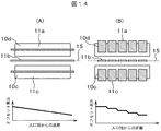
- FIG. 2 is an explanatory diagram of the effect of this method.
- FIG. 3 is an explanatory diagram of the effect of this method.
- Voltage control diagram Explanatory drawing of the effect of this system.
- FIG. 10 is a sequence diagram of the third embodiment. Explanatory drawing of Example 3.
- FIG. 1 is a schematic configuration diagram of a triple quadrupole mass spectrometer in an embodiment of the present invention.
- Explanatory drawing which shows an example of the power supply for electric field formation in this invention Example, and the z-axis direction electrostatic field formed by it.
- Explanatory drawing which shows an example of the oscillation frequency of the ion with respect to the mass charge ratio in the Example of this invention.
- Explanatory drawing which shows an example of the auxiliary
- Example. 1 is a schematic configuration diagram of a quadrupole-flight mass spectrometer in an embodiment of the present invention.
- FIG. 1 is a schematic configuration diagram of a quadrupole-flight mass spectrometer in an embodiment of the present invention.
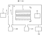
- FIG. 1 is a configuration diagram of the mass spectrometer of this method.
- 1A is an overall view of the apparatus
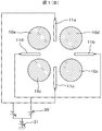
- FIG. 1B is an axial sectional view of the quadrupole mass filter section 7
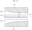
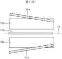
- FIGS. 1C and 1D are radial sectional views of the apparatus.
- Ions generated by ion source 1 such as electrospray ion source, atmospheric pressure chemical ion source, atmospheric pressure photoion source, atmospheric pressure matrix assisted laser desorption ion source, matrix assisted laser desorption ion source pass through pore 2 And introduced into the differential exhaust section 5.
- the differential exhaust section is exhausted by a pump 20.
- Ions from the differential evacuation unit 5 pass through the pores 3 and are introduced into the analysis unit 6.
- the analysis unit is evacuated by the pump 21 and maintained at 10 ⁇ 1 Torr or less (1.3 Pa or less). Ions are introduced into the quadrupole mass filter unit 7.
- the quadrupole mass filter unit 7 includes a quadrupole rod electrode (10a, 10b, 10c, 10d) and a quadrupole electrostatic electrode (11a, 11b, 11c, 11d).
- the quadrupole electrostatic electrode is an electrode for forming an electrostatic electric field on the center of the rod axis. An example is shown in FIG. A plate-like quadrupole electrostatic electrode (11 a, 11 b, 11 c, 11 d) is inserted into the center of the gap between adjacent quadrupole rod electrodes 10.
- Quadrupole electrodes 11 quadrupole at the inlet end side of the rod electrode 10 has a longer distance r a quadrupole electrode 11 and the central axis 15 of the quadrupole, r a is shortened at the outlet end It is in shape.
- a rod-shaped electrode as shown in FIG. 1D may be inserted. It is cheaper to insert a rod-shaped electrode, but the influence of disturbing the quadrupole RF electric field is larger than that of a plate-shaped electrode.
- the mass analysis unit has a voltage control unit 19 that controls the voltage of the electrodes constituting the quadrupole mass filter unit 7. Ions discharged from the quadrupole mass filter unit 7 are detected by the detector 8.
- the detector an electron multiplier tube or a combination type of a scintillator and a photomultiplier tube is generally used.
- the offset potential of the quadrupole rod electrode 10 may be applied with + ⁇ several tens of volts depending on the front and rear electrode voltages.
- the quadrupole will be described. It is defined as a value when the offset potential of the rod electrode 10 is zero.
- a high frequency voltage (quadrupole RF voltage) having an amplitude of 100 V to 5000 V and a frequency of about 500 kHz to 2 MHz is applied to the quadrupole rod electrode 10.
- Opposing quadrupole rod electrodes ((10a, 10c) and (10b, 10d) in the figure: in accordance with this definition) are applied with a quadrupole RF voltage having the same phase while the adjacent quadrupole rods are opposed to each other.
- An antiphase quadrupole RF voltage is applied to the electrodes ((10a, 10b), (10b, 10c), (10c, 10d), and (10d, 10a): in accordance with this definition hereinafter).
- a positive electrostatic voltage is applied to the quadrupole electrostatic electrode 11 as a quadrupole electrostatic voltage to a pair (11a, 11c or 11b, 11d) facing each other among the quadrupole static electrodes 11, and the other pair.
- a negative electrostatic voltage having the same amplitude is applied to (11b, 11d or 11a, 11c).
- the amplitude of the electrostatic voltage at this time is defined as the amplitude of the quadrupole electrostatic voltage.
- an electrostatic voltage having the same polarity and the same amplitude is applied to all the quadrupole electrostatic electrodes as an offset voltage superimposed on the quadrupole electrostatic voltage to the quadrupole electrostatic electrode 11.
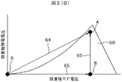
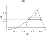
- the quadrupole mass filter In the quadrupole mass filter, only ions existing inside the stable region 60 of FIGS. 2B and 2C can pass through the quadrupole mass filter.
- the stable region is different for each ion m / z, and ions having a small m / z to a large ion are arranged in the relationship shown in FIG. If a quadrupole RF voltage and a quadrupole static voltage are selected and controlled near the apex of a certain m / z stable region by the voltage control unit, only ions of that m / z can be transmitted. .
- the quadrupole RF voltage and the quadrupole static voltage pass through the vicinity of the apex of the stable region (61, 62, 63) of each m / z ion as shown by the scan line 73 shown in FIG.
- a mass spectrum can be obtained by scanning the quadrupole RF voltage while maintaining the voltage relationship.
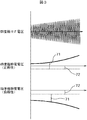
- the measurement sequence at this time is shown in FIG.
- the voltage applied to the quadrupole static electrode 11 is shown in FIG. 3 separately for an electrode to which a positive quadrupole electrostatic voltage is applied and an electrode to which a negative quadrupole electrostatic voltage is applied. It was.
- an offset voltage 72 of about ⁇ 1 to ⁇ 100 V with respect to the offset potential of the quadrupole rod electrode is applied to the quadrupole electrostatic electrode 11. Further, a quadrupole electrostatic voltage 71 is applied so as to be superimposed on the offset voltage. The amplitude of the quadrupole electrostatic voltage 71 is controlled so as to satisfy the relationship of the scan line 73 in FIG. 2A according to the amplitude of the quadrupole RF voltage. At this time, regarding the quadrupole electrostatic voltage component obtained by subtracting the offset voltage, the amplitudes of the positive voltage and the negative voltage are always the same. When measuring negative ions, only the polarity of the offset voltage in the measurement sequence of FIG. 3 need be reversed.
- the distance between the quadrupole electrostatic electrode 11 and the central axis 15 decreases as the ions travel on the central axis toward the exit end. For this reason, the quadrupole electrostatic voltage felt by ions increases. The ions travel upward in the stable region of FIG. 2C and finally reach a point C corresponding to the exit end with the highest quadrupole electrostatic voltage.
- the mass resolution of the quadrupole mass filter unit 7 depends on the magnitude of the quadrupole electrostatic voltage felt by ions near the exit end.
- an electric field gradient is formed on the central axis, and the ions can be accelerated toward the exit end of the quadrupole mass filter. it can.
- the gradient of the electric field gradient depends on the shape of the quadrupole electrostatic electrode 11. Distance r a quadrupole electrode 11 and the central axis 15, by using the quadrupole electrodes 11 shaped to increase with the square of the distance from the exit of the quadrupole mass filter, the electric field on the central axis
- the gradient is constant regardless of the position on the central axis, and ions can be accelerated at a constant acceleration.
- the potential generated by the quadrupole electrostatic voltage is always 0 on the central axis. It is only necessary to consider the potential of the current. Further, even if an offset potential is applied only to the two quadrupole electrostatic electrodes (11a, 11c or 11b, 11d), an electric field gradient can be formed on the central axis.
- Example 1 it is not necessary to use a plurality of quadrupole rods as in the case of using a bull baker lens. For this reason, the structure can be simplified. Further, since only the quadrupole RF voltage is applied to the quadrupole rod electrode, there is an advantage that the power source is simplified. Further, in this method, since an electric field gradient can be formed on the central axis, ion retention does not occur and high transmittance can be realized even under high pressure (0.5 mTorr or more).
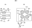
- Example 2 a configuration in which both ends of the quadrupole electrostatic electrode 11 are present inside both ends of the quadrupole rod electrode 10 will be described.
- FIG. 5 (A) is a sectional view in the axial direction of a mass spectrometer that implements this method.
- FIG. 5B is a radial cross-sectional view as viewed from the direction of the arrow shown in FIG.
- FIG. 5B shows the state of voltage application to the quadrupole electrostatic electrode 11.
- the device configuration up to the quadrupole mass filter unit 7 and the device configuration after the quadrupole mass filter unit 7 are the same as those in the first embodiment, and will be omitted.
- a quadrupole electrostatic electrode is arranged on the inner side of the quadrupole rod so that the quadrupole mass filter unit 7 is composed of an inlet-side converging unit 40, a mass separating unit 41, and a soot-exit-side converging unit 42. .
- the quadrupole mass filter unit 7 is composed of an inlet-side converging unit 40, a mass separating unit 41, and a soot-exit-side converging unit 42.
- the quadrupole electrostatic voltage is not applied to the entrance side converging unit 40. Therefore, the loss of ions due to fringing field can be reduced by the same effect as the bull-baker lens. In addition, loss of ions due to fringing field formed at the exit end by the exit side converging portion 42 can be avoided.
- the ions discharged from the mass separation unit 41 are in a state where the radial distribution is widened, but the kinetic energy is cooled by collision with the neutral gas while passing through the outlet side converging unit 42, and the radial direction The ion distribution is converged.
- Example 2 compared with (Example 1), there is no electric field gradient on the central axis, so that the ion transmittance is taken.
- the processing of the quadrupole electrostatic electrode is simpler (Example 1) and can be manufactured at a lower cost.
- the efficiency of introducing ions into the subsequent mass analyzing unit during tandem mass analysis is higher than that in the first embodiment.
- Example 3 a configuration in which the present system is incorporated in a linear ion trap will be described.
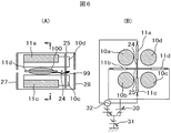
- the structure of the linear ion trap part is shown in FIG.
- the linear ion trap section includes an inlet end electrode 27, a quadrupole rod electrode 10, an outlet end electrode 28, a quadrupole electrostatic electrode 11, a trap wire electrode 24, and a lead wire electrode 25.
- a buffer gas is introduced into the linear ion trap portion and is maintained at about 10 ⁇ 4 Torr to 10 ⁇ 2 Torr (1.3 ⁇ 10 ⁇ 2 Pa to 1.3 Pa).
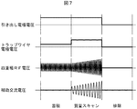
- Fig. 7 shows the measurement sequence of the linear ion trap. Measurement is performed in three sequences: trap, mass scan, and exclusion. During the trapping time, a voltage having the same polarity as the ions to be measured is applied to the inlet end electrode 27 and the trap wire electrode 24. For this reason, the ions introduced into the linear ion trap portion are trapped in a region 100 sandwiched between the inlet end electrode 27, the quadrupole rod electrode 10, and the trap wire electrode 24. The voltage applied to the quadrupole electrostatic electrode 11 during the trap time and the effect will be described later.
- a quadrupole RF voltage is applied while applying an auxiliary AC voltage (amplitude 0.1 V to 100 V, frequency 10 kHz to 500 kHz) between a pair of opposed quadrupole electrostatic electrodes 11 (a, b). Ions are ejected in a mass selective manner by changing the amplitude.
- the inlet end electrode 27 is set to about 10 to 100 V
- the outlet end electrode 28 is set to about 0 to ⁇ 50 V
- the trap wire electrode 24 is set to about 5 to 30 V
- the lead wire electrode 25 is set to about 0 to ⁇ 50 V.
- the ions of m / z that resonate with the auxiliary AC voltage are vibrated and excited in the radial direction, and are ejected in the axial direction beyond the potential barrier of the trap wire electrode 24 as shown by the trajectory 99 shown in FIG.
- m / z ions that do not resonate with the auxiliary AC voltage remain in the region 100 sandwiched between the inlet end electrode 27, the quadrupole rod electrode 10, and the trap wire electrode 24. If the intensity of the quadrupole electrostatic electric field is set to 0 during the mass scan time, the distortion of the quadrupole RF electric field can be alleviated and the mass resolution of the linear ion trap can be improved. Finally, in the exclusion time, the voltage amplitude of the quadrupole RF voltage is set to 0, and all ions are ejected out of the trap.
- r 0 is the distance between the rod electrode 10 and the center of the quadrupole
- m is the ion m / z
- W is the angular frequency of the quadrupole RF voltage
- U is the intensity of the quadrupole electrostatic voltage
- V is four. The amplitude of the bipolar RF voltage is shown.
- the m / z range of trapped ions can be adjusted by changing the intensity of the quadrupole electrostatic voltage. If the quadrupole electrostatic voltage is made higher as shown in the figure, the m / z range of trapped ions becomes narrower. The smaller the mass range of trapped ions, the higher the effect of suppressing space charge. On the other hand, since the mass range that can be analyzed in a single trap operation is narrowed, the ion utilization efficiency decreases. Here, the ion utilization efficiency indicates the proportion of ions that are selectively ejected by mass among the ions introduced into the analysis unit.
- Example 4 describes a method for realizing a triple quadrupole mass spectrometer that can operate under high pressure and can be manufactured at low cost by using this method.
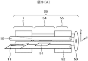
- FIG. 9A is a block diagram of a mass spectrometer that implements this method.
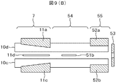
- 9B and 9C are cross-sectional views.
- FIG. 10 shows the state of voltage application to the quadrupole electrostatic electrode 11, the dissociation electrode 51, and the blade electrode 52.
- the device configuration up to the triple quadrupole unit 50 and the device configuration after the mass analysis unit are the configurations in which the quadrupole mass filter unit of Example 1 is replaced with the triple quadrupole unit 50.
- the triple quadrupole unit 50 includes a quadrupole rod electrode 10, four quadrupole electrostatic electrodes 11, two collision dissociation electrodes 51, and two blade electrodes 52.
- the offset voltage applied to the quadrupole electrostatic electrode 11, the collision dissociation electrode 51, and the blade electrode 52 is set so that the electrostatic potential decreases in the order of the quadrupole electrostatic electrode, the collision dissociation electrode, and the blade electrode.
- the operation of the quadrupole mass filter unit 7 is the same as (Example 1) and will not be described.
- the ions that have passed through the quadrupole mass filter unit 7 are introduced into the dissociation unit 54.
- an auxiliary AC voltage (amplitude 0.01 V to 100 V, frequency 10 kHz to 500 kHz) at which the ion to be dissociated resonates is applied to the collision dissociation electrode 51 to collide with the m / z ion to be dissociated. Vibration excitation is performed in the direction of the dissociation electrode 54.
- the vibrationally excited ions are dissociated into fragment ions by collision with neutral molecules. Fragment ions generated by the dissociation unit 54 are introduced into the mass analysis unit 55.
- a potential barrier is formed by applying a voltage of about 0.1-100 V to the outlet end electrode 53.
- an auxiliary AC voltage (amplitude 0.01 V to 100 V, frequency 10 kHz-500 kHz) is applied to the blade electrode 52, m / z ions that resonate with the frequency of the auxiliary AC voltage are excited in the direction of the blade electrode 52. Excited ions are discharged from the outlet end electrode 53 through the potential barrier because the energy in the axial direction is increased by the Fringing field. Since ions that are not resonantly excited cannot pass the potential barrier of the outlet end electrode 53, they remain inside the mass analysis unit 55.
- the frequency of the auxiliary AC voltage applied to the blade voltage 52 is swept, a mass spectrum of fragment ions can be obtained.
- the pressure of the mass analysis part 55 is made lower than that of the dissociation part 54, so that the fragment ions can be prevented from further decomposition in the mass analysis part. .
- the mass resolution and sensitivity in the mass analyzer 55 are improved.
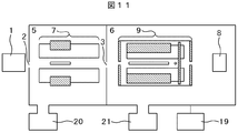
- Ions generated by the ion source 1 pass through the pores 2 and are introduced into the differential exhaust unit 5.
- the differential exhaust section 5 is exhausted by the pump 20 and is maintained at about 10 ⁇ 1 Torr or less (13 Pa or less).
- the ions introduced into the differential exhaust unit 5 are mass-separated by the quadrupole mass filter unit 7, and ions in a specific mass range that have passed through the quadrupole mass filter unit 7 pass through the pores 3 and the analysis unit 6.
- Introduced into The analysis unit 6 is evacuated by the pump 21 and maintained at 10 ⁇ 4 Torr or less (1.3-2 Pa or less).
- the ions introduced into the analysis unit 6 are mass-separated by the ion trap unit 9 and then detected by the detector 8.
- the structure and voltage control of the quadrupole mass filter unit 7 are the same as in Example 2 and are omitted.
- the ion trap unit 9 only needs to be capable of trapping ions in a certain mass range and discharging them in a mass selective manner.
- the operation of the ion trap unit may repeat the trap, mass scan, and discharge operations as shown in the third embodiment, or may perform mass scan while introducing ions into the ion trap.
- the mass of the ions discharged from the quadrupole mass filter unit 7 is adjusted in accordance with the mass range of the ions discharged from the ion trap unit 9 in the same manner as in the case of the third embodiment.
- the space charge of the ion trap can be suppressed. If the mass range of the ions that pass through the quadrupole mass filter unit 7 is narrowed, the amount of ions introduced into the ion trap unit 9 is reduced, so that the effect of suppressing the space charge of the linear ion trap unit becomes higher. On the other hand, ion utilization efficiency decreases.
- the mass range of ions passing through the quadrupole mass filter unit 7 and the mass range of ions ejected from the ion trap unit are controlled in conjunction with each other. May be.
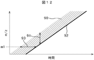
- FIG. 12 shows the mass range 90 of ions passing through the quadrupole mass filter section with time on the horizontal axis and m / z on the vertical axis.
- the m / z 91 of ions discharged from the ion trap part is also shown in the same figure.
- the m / z range of ions passing through the quadrupole mass filter unit and the m / z of ions ejected from the ion trap unit are scanned at the same speed.
- the range of m / z of ions ejected from the quadrupole mass filter unit is set to be larger than m / z of ions ejected from the ion trap unit.
- the time 93 during which ions of a certain m / z are accumulated in the ion trap part is determined by the m / z range of ions passing through the quadrupole mass filter part and the scanning speed.
- the advantage of placing the quadrupole mass filter section and the ion trap section in vacuum chambers with different pressures will be described. Since the differential exhaust section has a high pressure, the ion cooling efficiency is high, and the energy distribution of ions spread by the quadrupole electrostatic electric field of the quadrupole mass filter can be efficiently converged. For this reason, ions whose energy distribution has converged can be efficiently introduced into the subsequent mass analysis unit.
- the pressure inside the ion trap part can be set low by placing the ion trap part in the analysis part where the pressure is low, and the mass resolution and the discharge efficiency compared with the conditions where the pressure inside the ion trap part is high are reduced. improves.
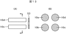
- FIG. 13A is an axial cross-sectional view of the RF-only quadrupole mass filter section.
- FIG. 13B is a radial cross-sectional view seen from the direction of the arrow shown in FIG.
- the RF only quadrupole mass filter consists of a quadrupole rod electrode and an outlet end electrode. When measuring positive ions, a potential barrier is formed by applying a voltage of about 0.1-100 V to the outlet end electrode 53.
- Ions located at the boundary of the stable region have a larger radius in the radial direction and the energy in the axial direction is increased by the Fringing field, so that they are discharged from the outlet end electrode 53 beyond the potential barrier. If the quadrupole RF voltage is swept, a mass spectrum can be obtained.
- the resolution of the RF ⁇ only quadrupole mass filter decreases as the energy distribution of the incident ions increases, but in this embodiment, the ion energy distribution in the axial direction can be converged by the quadrupole mass filter section with high pressure. it can.
- the shape and material of the quadrupole electrostatic electrode 11 are determined by the strength of the quadrupole electrostatic electrode on the entrance side of the quadrupole electrostatic electrode 11 and the potential due to the offset voltage. What is necessary is just to be able to set so that it may become low compared with the exit side of a quadrupole electrostatic electrode.
- the quadrupole electrostatic electrode 11 is formed of a resistor, and quadrupole electrostatic voltages and offset voltages having different strengths are applied to the entrance side end and the exit side end of the quadrupole electrostatic electrode 11, or
- the quadrupole electrostatic electrode 11 may be divided into two or more in the axial direction, and quadrupole electrostatic voltage and offset voltage having different strengths may be applied to the respective electrodes.
- FIG. 14A shows an axial sectional view of an example in which the quadrupole electrostatic electrode 11 is formed of a resistor
- FIG. 14B shows a sectional view of an example in which the quadrupole electrostatic electrode 11 is divided. .
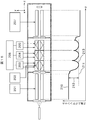
- FIG. 15 shows a schematic configuration diagram of an apparatus according to an embodiment when the present invention is employed in a triple quadrupole mass spectrometer. Further, FIG. 16 shows a power source for forming an electric field and a z-axis direction electrostatic field formed thereby.
- the ion source 101 ionizes the sample by applying a voltage of several kV from a DC power source.
- the positively or negatively charged ions pass through the pores 102 having a diameter of about 0.2 to 0.8 mm and are introduced into the vacuum.
- the first-stage quadrupole 103 that is reserved in the subsequent stage is a quadrupole that creates a linear quadrupole electric field.
- an AC voltage is superimposed on the DC voltage and applied.
- This specific mass-to-charge ratio is defined as the mass-to-charge ratio of the target ion for structural analysis.
- This target ion is an ion that undergoes collision-induced dissociation and is a target ion.
- the target ions are introduced into the collision chamber 105 through the inlet pore 104 provided in the subsequent stage.
- the inside of the collision chamber 105 maintains a pressure of about several millitorr by introducing neutral molecules such as argon and nitrogen.
- the second-stage quadrupole 106, the first-stage feather electrode pair 107, the second-stage feather electrode pair 108, and the third-stage feather electrode pair 109 which are components of the present invention, are arranged.
- the number of stages of the wing electrode is not limited to three, and the number of stages reaches from one end to the other end in the length direction of the second-stage quadrupole 106.
- the first wing electrode pair 107 includes a front wing electrode 107a and a rear wing electrode 107b, and is mirror-symmetric with each other.
- the first stage is denoted by the reference numeral, but the second stage feather electrode pair 108 and the third stage feather electrode pair 109 are similarly configured by the front and rear blade electrodes.
- a high-frequency voltage and a DC voltage are applied to the second-stage quadrupole 106 by being supplied from the DC / AC power supply 202 for the second-stage quadropole.
- a well-type potential in the xy plane is formed with a high-frequency voltage, and ions are captured in the xy direction. Further, the DC voltage applies a voltage for trapping and cleaving ions.
- the first-stage wing electrode pair 107, the second-stage wing electrode pair 108, and the third-stage wing electrode pair 109 are electrodes that form a harmonic potential therein, respectively, and the first-stage wing electrode pair DC power supply 203, A harmonic potential in the z-axis direction is created by applying a DC voltage from the DC power supply 204 for the second stage wing electrode pair and the DC power source 205 for the third stage wing electrode pair, and ions are captured in the z-axis direction.
- the z-direction micropore 110 is a vacuum partition that separates the collision chamber 105 and the mass separator (quadrupole mass spectrometer) 111, and acts as an electrode by applying a DC voltage. Ions discharged from the collision chamber 105 pass through the pores 110 and are introduced into the mass separation unit (quadrupole mass spectrometer) 111.
- the mass separation unit (quadrupole mass spectrometer) 111 includes a third-stage quadrupole 112 and a detector 113.
- a third-stage quadrupole 112 By supplying from the DC / AC power supply 207 for the third-stage quadrupole, an AC voltage is superimposed on the DC voltage and applied, so that ions are mass separated by the third-stage quadrupole 112 and detected by the detector 113.
- an electrostatic field shown in FIG. 16 is formed on the z-axis.
- the target ions introduced into the collision chamber have a potential difference between the first-stage quadropole DC voltage potential 210 of the first-stage quadropole 103 and the second-stage quadrupole DC voltage potential 211 of the second-stage quadropole 106 of the collision chamber 105.
- the kinetic energy is obtained by the potential difference 212 for collision-induced dissociation and collision with neutral molecules causes ion cleavage. Since ion cleavage sites are random, fragment ions having a wide mass-to-charge ratio range are generated.
- Fragment ions are trapped inside by the harmonic potential 213 formed by the first-stage wing electrode pair, which is the harmonic potential formed by the front wing electrode 107a and the rear wing electrode 107b constituting the first-stage wing electrode pair 107. Then, it vibrates in the z-axis direction at a frequency unique to the mass-to-charge ratio.
- the wing electrode pair alternating voltage 206 having the same frequency as the vibration frequency of ions corresponding to the measurement mass-to-charge ratio range is applied to the front wing electrode 107a and the rear wing electrode 107b.
- This AC voltage is used as an auxiliary high-frequency voltage.
- the auxiliary high-frequency voltage is in antiphase with the front wing electrode 107a and the rear wing electrode 107b.
- the electrode to which the auxiliary high-frequency voltage is applied may be only one of the front wing electrode 107a and the rear wing electrode 107b.
- a DC voltage applied to the wing electrode pair is applied so as to apply an electric field gradient in the order of the first-stage wing electrode pair 107, the second-stage wing electrode pair 108, and the third-stage wing electrode pair 109.
- the DC voltage is set to be higher in the first stage than in the third stage.
- the ion is a negative ion, it is lowered.
- fragment ions are resonantly excited in the x-axis direction to obtain energy and obtain a potential that exceeds the harmonic potential, and are emitted to the second stage feather electrode pair 108 side. Then, the fragment ions are captured by the second stage wing electrode pair 108, and are subjected to voltage operation in the same manner as the first stage wing electrode pair 107, and are resonantly emitted in the direction of the third stage wing electrode pair 109. By sequentially repeating this, fragment ions can obtain energy in the direction of the third-stage quadropole 112.
- the signal of the fragment ion can be measured.
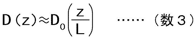
- a z-axis direction potential D (z) is created on the center z-axis of the quadrupole by applying a DC voltage to the front wing electrode 107a and the rear wing electrode 107b.
- the z-axis direction potential D (z) is expressed by Equation 3 by the distance z from the center between the front wing electrode 107a and the rear wing electrode 107b.
- D 0 is the harmonic potential depth
- L is the distance from the center between the front wing electrode 107a and the rear wing electrode 107b to the end point of the wing electrode.
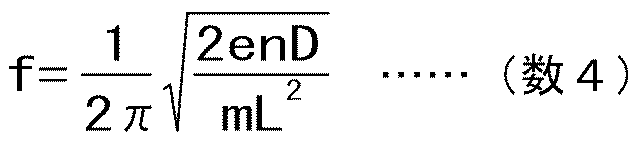
- the ions When an auxiliary high-frequency voltage having a frequency corresponding to the mass-to-charge ratio is applied to the wing electrode with respect to ions to be resonantly excited, the ions can be resonantly excited in the z-axis direction to obtain kinetic energy in the z-axis direction.
- the AC voltage is applied to the two wing electrodes in opposite phases, or is applied to only one of them.
- the frequency of the auxiliary high-frequency voltage is calculated from the mass-to-charge ratio which is m / n in Equation 4 and applied in a superimposed manner.
- the amplitude of the frequency at which the high-mass-to-charge ratio resonates is increased with respect to the low mass-to-charge ratio.
- L is 25 mm
- the quadrupole DC voltage is 2 V
- the DC voltages of the first, second, and third stage blade electrode pairs are 11 V, 9 V, and 7 V. Since the harmonic potential depth D 0 of each wing electrode pair can be estimated from the difference between the DC voltage of the wing electrode pair and the DC voltage of the quadrupole, the harmonic potential depth of each wing electrode pair is about 9V, 7V, and 5V. Become.
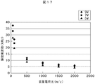
- FIG. 17 shows the relationship between the vibration frequency of ions and the mass-to-charge ratio calculated from Equation (4).
- the vibration frequency is inversely proportional to the mass-to-charge ratio. The lower the mass-to-charge ratio, the higher the vibration frequency, and the higher the mass-to-charge ratio, the lower the vibration frequency.
- the vibration frequency is proportional to the harmonic potential depth. For example, when the mass to charge ratio is m / z 500, the vibration frequency is about 13 kHz at a harmonic potential depth of 9 V. When an auxiliary high-frequency voltage of this frequency is applied to the pair of wing electrodes, the ions are resonantly excited to obtain kinetic energy in the z-axis direction.
- an auxiliary high-frequency voltage obtained by synthesizing a frequency of 4 to 38 kHz is applied in order to resonantly excite ions having a mass-to-charge ratio in the range of m / z 50 to 2000.
- ions in the range of m / z 50 to 2000 are resonantly excited, and energy can be obtained in the z-axis direction.
- this auxiliary high frequency voltage can be arbitrarily changed for each frequency, the energy given to the mass to charge ratio can be arbitrarily changed. That is, crosstalk can be reduced in a wide mass range by adjusting the voltage of the auxiliary high-frequency voltage so that the crosstalk becomes small for each ion that crosstalks and adjusting the applied energy.
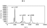
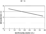
- the voltage of the auxiliary high-frequency voltage may be adjusted so that the intensity decreases from the ion intensity of the crosstalk mass spectrum. For example, when the crosstalk is large in the ions with a high mass-to-charge ratio, as shown in FIG.
- the ions with a high mass-to-charge ratio with a low oscillation frequency will have a low mass-to-charge ratio.
- a large energy is given to the ions, and as a result, crosstalk of a wide range of ions can be reduced without depending on the mass-to-charge ratio.
- FIG. 19 shows a schematic configuration diagram of the quadrupole-time-of-flight mass spectrometer of the present embodiment.
- the range 501 from the ion source to the pores shown in FIG. 15 has the same configuration as that of the first embodiment, and the mass separation unit (time-of-flight mass spectrometer) 502 provided in the subsequent stage has a time-of-flight mass. It is an analyzer.
- the mass separator (time-of-flight mass spectrometer) 502 includes an accelerating electrode 503 that accelerates ions, a reflective electrode 504 that makes kinetic energy uniform, and a detector 505 that detects ions and converts them into current values.
- a direct acceleration reflection type time-of-flight mass spectrometer is taken as an example, but it can also be implemented in a method of accelerating in the z-axis direction or a method of arranging a detector in the direction of ion travel without using a reflective electrode.
- Fragment ions are generated by the configuration and voltage in the range 501 from the ion source to the pore shown in FIG. 15 and transported to the time-of-flight mass spectrometer 502.
- a high voltage of a transient signal is applied to the accelerating electrode 503, so that ions obtain kinetic energy and equalize the kinetic energy with the reflective electrode 504, and then the time to reach the detector 505 is obtained. measure.
- this time By converting this time into a mass-to-charge ratio and using the current value from the detector as the intensity, a mass spectrum of fragment ions can be obtained.
- the mass separation unit 502 time-of-flight mass spectrometer 502
- other mass separators such as an ion cycloton mass spectrometer (FT-ICR)
- FT-ICR ion cycloton mass spectrometer
- tandem mass spectrometers such as triple quadrupole mass spectrometers (Triple Q) and quadrupole-time-of-flight mass spectrometers (Q-TOF) are capable of MS / MS.
- This is a mass spectrometer that has excellent characteristics in structural analysis and quantitative analysis.
- a collision cell is arranged in the middle of the tandem mass spectrometer, and collision induced dissociation (CID: Collision Induced Dissociation) is performed.
- CID collision induced dissociation
- CID is the collision of an ion with a neutral molecule to break the intermolecular bond.
- a decrease in kinetic energy at the time of collision causes a decrease in ion velocity and an increase in velocity distribution. Therefore, when multiple types of samples (ions) are measured, the previous result remains in the later result. This is generally referred to as crosstalk, and causes unnecessary display of structural information and a decrease in quantitative accuracy. Furthermore, as the mass-to-charge ratio of ions increases, the problem due to the crosstalk increases.
- a wing electrode for creating a multi-stage harmonic potential is arranged in the collision cell. Fragment ions generated by collision-induced dissociation are trapped inside the first-stage harmonic potential.
- the trapped ions vibrate in the axial direction at a frequency depending on the mass, if an alternating voltage corresponding to this frequency is applied to the wing electrode, the ions resonate in the axial direction and move toward the detector. You can get energy. With this energy, the time spent in the collision cell can be shortened, and crosstalk can be reduced. Further, even for a high-mass ion having a relatively low moving speed, the ion velocity can be increased over the entire mass range by selectively increasing the voltage having a frequency corresponding to the high mass.
- the axial ion acceleration by resonance excitation and the voltage at a frequency corresponding to a high mass are selectively increased to shorten the time for ions in a wide mass-to-charge ratio range to stay in the collision chamber and reduce crosstalk. can do.
- An ion source that ionizes the sample, a first mass separation unit that selects a target ion from ions generated in the ion source, a collision chamber that performs collision-induced dissociation on the selected ion, and a collision
- a mass spectrometer including a second mass separation unit that again mass-separates fragment ions generated by induced dissociation, and a detector that detects ions, a harmonic potential is formed in the collision chamber, and collision induction is performed in the collision chamber. Resonate excitation of fragment ions generated by dissociation and give energy to the ions in the axial direction.
- the collision chamber captures ions by forming a pseudo-well-type potential in a direction orthogonal to the traveling direction of the ions by applying a high-frequency voltage to a multipole such as a quadrupole or an octopole. thing.
- the harmonic potential formed in the inside of the collision chamber is formed in the axial direction by arranging a planar plate electrode and applying a DC voltage.
- ions having a total mass to charge ratio are excited by superimposing voltages having a plurality of frequencies at which ions resonate with an AC voltage for resonance excitation.
- the amplitude of the AC voltage for resonance excitation can be changed for each frequency unit, and the energy given to the ions of each mass to charge ratio can be set individually.
- the amplitude is controlled for each frequency so that ions of the first mass-to-charge ratio are equivalent to the velocity of ions having a mass-to-charge ratio lower than the first mass-to-charge ratio.
- the sample is ionized, the target ion is selected from the generated ions, collision-induced dissociation is performed on the selected ions, and fragment ions generated by the collision-induced dissociation are again mass separated to detect the ions.
- the generated fragment ions are resonantly excited by a harmonic potential and energy is given to the ions in the axial direction.
- the harmonic potential is formed in the axial direction by applying a DC voltage to the planar plate electrode.
- the amplitude of the AC voltage for resonance excitation can be changed for each frequency unit, and the energy to be given to the ions of each mass to charge ratio can be individually set.
- Range of the q value of ions in the stable region when the quadrupole electrostatic voltage is 0, and 80... The stable region when the a value is a1.
Landscapes
- Chemical & Material Sciences (AREA)
- Analytical Chemistry (AREA)
- Other Investigation Or Analysis Of Materials By Electrical Means (AREA)
- Electron Tubes For Measurement (AREA)
Abstract
Description
されている。本分析計は軸方向に直流電圧電界を形成することで、イオンの加速を行う方法である。しかし、軸方向に対する電位差は小さく、質量数が高くなるほど効果が小さくなる課題を持つ。
ここで、四重極静電電極は、ロッド軸中心上に静電電場を形成させる電極である。図1にはその例が記載されている。板状の四重極静電電極(11a、11b、11c、11d)が、隣接した四重極ロッド電極10の間隙の中心部に挿入される。四重極静電電極11は四重極ロッド電極10の入口端側では四重極静電電極11と四重極の中心軸15の距離raが長く、出口端側ではraが短くなる形状にしている。板状の四重極静電電極を用いる代わりに、図1(D)に示すような棒状の電極を挿入してもよい。棒状の電極を挿入するほうが安価であるが、板状の電極よりも四重極RF電場を乱す影響が大きくなる。


101…イオン源、102,110…細孔、103…1段目クワドロポール、104…入口細孔、105…衝突室、106…2段目クワドロポール、107…1段目羽電極対、107a…前羽電極、107b…後羽電極、108…2段目羽電極対、109…3段目羽電極対、111…質量分離部(四重極形質量分析計)、112…3段目クワドロポール、113,505…検出器、201…1段目クワドロポール用直流/交流電源、202…2段目クワドロポール用直流/交流電源、203…1段目羽電極対用直流電源、204…2段目羽電極対用直流電源、205…3段目羽電極対用直流電源、206…羽電極対用交流電源、207…3段目クワドロポール用直流/交流電源、210…1段目クワドロポール直流電圧電位、211…2段目クワドロポール直流電圧電位、212…衝突誘起解離のための電位差、213…1段目羽電極対により形成される調和ポテンシャル、501…図15で示したイオン源から細孔までの範囲、502…質量分離部(飛行時間形質量分析計)、503…加速電極、504…反射電極。
Claims (32)
- イオンを生成するイオン源と、
イオンを輸送するイオン輸送部と、
特定の質量範囲のイオンを分離するイオン分離部と、
前記イオン分離部で分離されたイオンを検出する検出部からなる質量分析装置であって、
前記イオン分離部が、四重極高周波電場を形成する四重極ロッド電極と、前記四重極ロッド電極間に挿入される四重極静電電場を形成する電極と、少なくとも前記四重極静電電場を形成する電極の電圧を制御させる電圧制御部を有することを特徴とする質量分析装置。 - 請求項1に記載の質量分析装置において、前記四重極静電電場を形成する電極により、前記四重極ロッド電極の中心軸上に電界勾配が形成されることを特徴とする質量分析装置。
- 請求項1に記載の質量分析装置において、前記電圧制御部により印加される四重極静電電場の強度が、質量分析装置の入口側で小さく、出口側で大きいことを特徴とする質量分析装置。
- 請求項1に記載の質量分析装置において、イオンを前記イオン分離部の径方向に振動させる電極及び電源を持つことを特徴とする質量分析装置。
- 請求項1に記載の質量分析装置において、前記四重極静電電場を形成する電極は、前記四重極ロッド電極間に挿入された板状電極又は棒状の電極であることを特徴とする質量分析装置。
- 請求項5に記載の質量分析装置において、前記四重極静電電場を形成する電極とロッド軸中心との間の距離は、イオンの入口側の方が出口側よりも大きいことを特徴とする質量分析装置。
- 請求項6に記載の質量分析装置において、前記四重極静電電場を形成する電極は、前記イオン分離部のイオンの出口からの距離の2乗で四重極中心からの距離が増加する形状を有していることを特徴とする質量分析装置。
- 請求項1に記載の質量分析装置において、前記四重極静電電場を形成する電極には、前記電圧制御部により、対向する電極は同極性の静電電圧が印加され、隣接する電極は逆極性の静電電圧が印加されることを特徴とする質量分析装置。
- 請求項5に記載の質量分析装置において、前記四重極静電電極には、前記電圧制御部により、前記イオン分離部に導入されているイオンと逆極性のオフセット電圧が印加されることを特徴とする質量分析装置。
- 請求項1に記載の質量分析装置において、前記四重極ロッド電極の端よりも内側に、前記四重極静電電場を形成する電極が形成されていることを特徴とする質量分析装置。
- 請求項10に記載の質量分析装置において、前記四重極静電電極には、前記電圧制御部により、前記イオン分離部に導入されているイオンと同極性のオフセット電圧が印加されることを特徴とする質量分析装置。
- 請求項1に記載の質量分析装置において、前記イオン分離部は、前記四重極ロッド電極の外側にはイオンを前記イオン分離部内にトラップするイオントラップ電極を備え、トラップされたイオンに対し、前記電圧制御部は前記四重極静電電場を形成する電極に特定質量範囲のイオンのみ安定化させる振幅を有する電圧を印加することを特徴とする質量分析装置。
- 請求項1に記載の質量分析装置において、さらに、イオンを解離するイオン解離部と、前記イオン分離部とは異なる第2のイオン分離部を有することを特徴とする質量分析装置。
- 請求項13に記載の質量分析装置において、前記イオン分離部、前記イオン解離部、前記第2のイオン分離部は、共通の四重極ロッド電極上で、静電ポテンシャルがイオンの進行にしたがって低くなるように順にそれぞれ形成されていることを特徴とする質量分析装置。
- 請求項1に記載の質量分析装置において、前記イオン分離部と前記検出部との間に、前記イオン分離部とは異なる第2の分離部を有することを特徴とする質量分析装置。
- 請求項15に記載の質量分析装置において、前記第2の分離部は、四重極ロッド電極と出口側端電極を備えた分離部であることを特徴とする質量分析装置。
- 請求項1に記載の質量分析装置において、前記四重極静電電場を形成する電極は、抵抗体で形成したものであることを特徴とする質量分析装置。
- 請求項1に記載の質量分析装置において、前記四重極静電電場を形成する電極は、軸方向に分割された電極であることを特徴とする質量分析装置。
- 試料をイオン化するイオン源部と、
当該イオン源にて生成されたイオンの中から目的のイオンを選択する第1の質量分離部と、
選択されたイオンについて衝突誘起解離を行う衝突室と、
衝突誘起解離により生成したフラグメントイオンを再度質量分離する第2の質量分離部と、
イオンを検出する検出器を備える質量分析装置において、
衝突室内部に調和ポテンシャルを形成し、その衝突室内部において衝突誘起解離で生成したフラグメントイオンを共鳴励起し、前記イオンへ軸方向にエネルギーを与えることを特徴とする質量分析装置。 - 請求項19において、
前記衝突室は、クワドロポールやオクタポール等のマルチポールに高周波電圧を印加することにより、イオンの進行方向に対し直交方向に擬似的な井戸型ポテンシャルを形成することで、イオンを捕捉することを特徴とする質量分析装置。 - 請求項19において、
前記衝突室内部に形成する調和ポテンシャルは、平面板状の電極を配置し、直流電圧を印加することで軸方向に形成することを特徴とする質量分析装置。 - 請求項19において、
調和ポテンシャルに交流電圧を重畳することでイオンを共鳴励起させることを特徴とする質量分析装置。 - 請求項22において、
共鳴励起させるための交流電圧を、イオンが共鳴する複数の周波数の電圧を重畳することで全質量電荷比のイオンを励起することを特徴とする質量分析装置。 - 請求項23において、
共鳴励起させるための交流電圧を、各周波数単位にその振幅を変更可能とし、各質量電荷比のイオンに与えるエネルギーを個別に設定可能とすることを特徴とする質量分析装置。 - 請求項24において、
第1の質量電荷比のイオンが、前記第1の質量電荷比より低い質量電荷比のイオンの速度と同等になるように周波数別に振幅を制御することを特徴とする質量分析装置。 - 試料をイオン化し、
当該生成されたイオンの中から目的のイオンを選択し、
選択されたイオンについて衝突誘起解離を行う
衝突誘起解離により生成したフラグメントイオンを再度質量分離し、
イオンを検出する質量分析方法において、
前記生成したフラグメントイオンを調和ポテンシャルにより共鳴励起し、イオンへ軸方向にエネルギーを与えることを特徴とする質量分析方法。 - 請求項26において、
前記選択されたイオンについて衝突誘起解離を行う場合、高周波電圧をマルチポールに印加することにより、イオンの進行方向に対し直交方向に擬似的な井戸型ポテンシャルを形成することで、イオンを捕捉することを特徴とする質量分析方法。 - 請求項26において、
前記調和ポテンシャルは、直流電圧を平面板状の電極へ印加することで軸方向に形成することを特徴とする質量分析方法。 - 請求項26において、
前記調和ポテンシャルに交流電圧を重畳することでイオンを共鳴励起させることを特徴とする質量分析方法。 - 請求項29において、
共鳴励起させるための前記交流電圧を、イオンが共鳴する複数の周波数の電圧を重畳することで全質量電荷比のイオンを励起することを特徴とする質量分析方法。 - 請求項30において、
共鳴励起させるための前記交流電圧を、各周波数単位にその振幅を変更可能とし、各質量電荷比のイオンに与えるエネルギーを個別に設定可能とすることを特徴とする質量分析方法。 - 請求項31において、
第1の質量電荷比のイオンが、前記第1の質量電荷比より低いイオンの速度と同等になるように周波数別に振幅を制御することを特徴とする質量分析方法。
Priority Applications (2)
| Application Number | Priority Date | Filing Date | Title |
|---|---|---|---|
| US13/123,901 US20110248157A1 (en) | 2008-10-14 | 2009-10-13 | Mass spectrometer and mass spectrometry method |
| JP2010533823A JP5603246B2 (ja) | 2008-10-14 | 2009-10-13 | 質量分析装置 |
Applications Claiming Priority (4)
| Application Number | Priority Date | Filing Date | Title |
|---|---|---|---|
| JP2008264750 | 2008-10-14 | ||
| JP2008-264750 | 2008-10-14 | ||
| JP2009014871 | 2009-01-27 | ||
| JP2009-014871 | 2009-01-27 |
Publications (1)
| Publication Number | Publication Date |
|---|---|
| WO2010044247A1 true WO2010044247A1 (ja) | 2010-04-22 |
Family
ID=42106419
Family Applications (1)
| Application Number | Title | Priority Date | Filing Date |
|---|---|---|---|
| PCT/JP2009/005320 Ceased WO2010044247A1 (ja) | 2008-10-14 | 2009-10-13 | 質量分析装置および質量分析方法 |
Country Status (3)
| Country | Link |
|---|---|
| US (1) | US20110248157A1 (ja) |
| JP (1) | JP5603246B2 (ja) |
| WO (1) | WO2010044247A1 (ja) |
Cited By (5)
| Publication number | Priority date | Publication date | Assignee | Title |
|---|---|---|---|---|
| WO2012067195A1 (ja) * | 2010-11-19 | 2012-05-24 | 株式会社日立ハイテクノロジーズ | 質量分析装置および質量分析方法 |
| JP2012521072A (ja) * | 2009-03-17 | 2012-09-10 | ディーエイチ テクノロジーズ デベロップメント プライベート リミテッド | イオン移動度に対するイオン光学ドレイン |
| CN112955998A (zh) * | 2018-12-19 | 2021-06-11 | 株式会社岛津制作所 | 质量分析装置 |
| JP2021534560A (ja) * | 2018-08-24 | 2021-12-09 | ディーエイチ テクノロジーズ デベロップメント プライベート リミテッド | 汚染を低減させ、質量分析法システムのロバスト性を向上させるためのrf/dcカットオフ |
| JP2022500813A (ja) * | 2018-09-07 | 2022-01-04 | ディーエイチ テクノロジーズ デベロップメント プライベート リミテッド | Rfイオントラップイオン装填方法 |
Families Citing this family (15)
| Publication number | Priority date | Publication date | Assignee | Title |
|---|---|---|---|---|
| JP5124293B2 (ja) * | 2008-01-11 | 2013-01-23 | 株式会社日立ハイテクノロジーズ | 質量分析計および質量分析方法 |
| US8314385B2 (en) * | 2011-04-19 | 2012-11-20 | Bruker Daltonics, Inc. | System and method to eliminate radio frequency coupling between components in mass spectrometers |
| US8785847B2 (en) * | 2012-02-15 | 2014-07-22 | Thermo Finnigan Llc | Mass spectrometer having an ion guide with an axial field |
| US10068752B2 (en) * | 2013-10-16 | 2018-09-04 | Dh Technologies Development Pte. Ltd. | Multiplexed precursor isolation for mass spectrometry |
| US9425032B2 (en) * | 2014-06-17 | 2016-08-23 | Thermo Finnegan Llc | Optimizing drag field voltages in a collision cell for multiple reaction monitoring (MRM) tandem mass spectrometry |
| CN106463332B (zh) * | 2014-06-23 | 2019-08-23 | Dh科技发展私人贸易有限公司 | 离子迁移率光谱测定法电力供应器的串扰补偿 |
| EP4657446A3 (en) * | 2014-11-14 | 2026-03-04 | D.E. Shaw Research, LLC | Suppressing interaction between bonded particles |
| US10607826B2 (en) * | 2015-07-28 | 2020-03-31 | University Of Florida Research Foundation, Incorporated | Atmospheric pressure ion guide |
| GB201615132D0 (en) * | 2016-09-06 | 2016-10-19 | Micromass Ltd | Quadrupole devices |
| CN107845561A (zh) * | 2016-09-18 | 2018-03-27 | 江苏可力色质医疗器械有限公司 | 一种减少交叉干扰的质谱碰撞反应池及分析方法 |
| US11728153B2 (en) * | 2018-12-14 | 2023-08-15 | Thermo Finnigan Llc | Collision cell with enhanced ion beam focusing and transmission |
| CN110310881B (zh) * | 2019-06-17 | 2024-08-16 | 宁波大学 | 用于离子串级质谱分析的碰撞诱导解离池及其使用方法 |
| CN116721586B (zh) * | 2023-06-19 | 2026-06-02 | 湖州师范大学 | 一种离子阱囚禁和四极杆质谱原理演示教具及其演示方法 |
| CN119069339B (zh) * | 2024-08-01 | 2025-07-22 | 暨南大学 | 一种多极杆-四极杆耦合碰撞池 |
| WO2026146396A1 (en) * | 2024-12-31 | 2026-07-09 | Dh Technologies Development Pte. Ltd. | Segmented t-bars |
Citations (2)
| Publication number | Priority date | Publication date | Assignee | Title |
|---|---|---|---|---|
| JPH1021871A (ja) * | 1996-07-02 | 1998-01-23 | Hitachi Ltd | イオントラップ質量分析装置 |
| JP2007095702A (ja) * | 1995-08-11 | 2007-04-12 | Mds Health Group Ltd | 軸電界を有する分析計 |
Family Cites Families (16)
| Publication number | Priority date | Publication date | Assignee | Title |
|---|---|---|---|---|
| US3129327A (en) * | 1961-12-12 | 1964-04-14 | Bell & Howell Co | Auxiliary electrodes for quadrupole mass filters |
| US6627912B2 (en) * | 2001-05-14 | 2003-09-30 | Mds Inc. | Method of operating a mass spectrometer to suppress unwanted ions |
| DE60309700T2 (de) * | 2002-05-30 | 2007-09-13 | MDS Inc., doing business as MDS Sciex, Concord | Verfahren und vorrichtung zur verringerung von artefakten in massenspektrometern |
| JP4659395B2 (ja) * | 2004-06-08 | 2011-03-30 | 株式会社日立ハイテクノロジーズ | 質量分析装置及び質量分析方法 |
| WO2007052372A1 (ja) * | 2005-10-31 | 2007-05-10 | Hitachi, Ltd. | 質量分析計及び質量分析方法 |
| JP4692310B2 (ja) * | 2006-02-09 | 2011-06-01 | 株式会社日立製作所 | 質量分析装置 |
| US7759637B2 (en) * | 2006-06-30 | 2010-07-20 | Dh Technologies Development Pte. Ltd | Method for storing and reacting ions in a mass spectrometer |
| WO2008044290A1 (fr) * | 2006-10-11 | 2008-04-17 | Shimadzu Corporation | Spectroscope de masse ms/ms |
| JP4918846B2 (ja) * | 2006-11-22 | 2012-04-18 | 株式会社日立製作所 | 質量分析装置及び質量分析方法 |
| US7633060B2 (en) * | 2007-04-24 | 2009-12-15 | Thermo Finnigan Llc | Separation and axial ejection of ions based on m/z ratio |
| US7847240B2 (en) * | 2007-06-11 | 2010-12-07 | Dana-Farber Cancer Institute, Inc. | Mass spectroscopy system and method including an excitation gate |
| JP5341323B2 (ja) * | 2007-07-17 | 2013-11-13 | 株式会社日立ハイテクノロジーズ | 質量分析装置 |
| EP2187204B1 (en) * | 2007-09-18 | 2017-05-17 | Shimadzu Corporation | Ms/ms mass spectrometer |
| US7675031B2 (en) * | 2008-05-29 | 2010-03-09 | Thermo Finnigan Llc | Auxiliary drag field electrodes |
| GB0810125D0 (en) * | 2008-06-03 | 2008-07-09 | Thermo Fisher Scient Bremen | Collosion cell |
| WO2010023873A1 (ja) * | 2008-08-29 | 2010-03-04 | 株式会社日立ハイテクノロジーズ | 質量分析装置 |
-
2009
- 2009-10-13 JP JP2010533823A patent/JP5603246B2/ja not_active Expired - Fee Related
- 2009-10-13 WO PCT/JP2009/005320 patent/WO2010044247A1/ja not_active Ceased
- 2009-10-13 US US13/123,901 patent/US20110248157A1/en not_active Abandoned
Patent Citations (2)
| Publication number | Priority date | Publication date | Assignee | Title |
|---|---|---|---|---|
| JP2007095702A (ja) * | 1995-08-11 | 2007-04-12 | Mds Health Group Ltd | 軸電界を有する分析計 |
| JPH1021871A (ja) * | 1996-07-02 | 1998-01-23 | Hitachi Ltd | イオントラップ質量分析装置 |
Cited By (10)
| Publication number | Priority date | Publication date | Assignee | Title |
|---|---|---|---|---|
| JP2012521072A (ja) * | 2009-03-17 | 2012-09-10 | ディーエイチ テクノロジーズ デベロップメント プライベート リミテッド | イオン移動度に対するイオン光学ドレイン |
| WO2012067195A1 (ja) * | 2010-11-19 | 2012-05-24 | 株式会社日立ハイテクノロジーズ | 質量分析装置および質量分析方法 |
| JP5530531B2 (ja) * | 2010-11-19 | 2014-06-25 | 株式会社日立ハイテクノロジーズ | 質量分析装置および質量分析方法 |
| US8829434B2 (en) | 2010-11-19 | 2014-09-09 | Hitachi High-Technologies Corporation | Mass spectrometer and mass spectrometry method |
| JP2021534560A (ja) * | 2018-08-24 | 2021-12-09 | ディーエイチ テクノロジーズ デベロップメント プライベート リミテッド | 汚染を低減させ、質量分析法システムのロバスト性を向上させるためのrf/dcカットオフ |
| JP2024071734A (ja) * | 2018-08-24 | 2024-05-24 | ディーエイチ テクノロジーズ デベロップメント プライベート リミテッド | 汚染を低減させ、質量分析法システムのロバスト性を向上させるためのrf/dcカットオフ |
| JP7820433B2 (ja) | 2018-08-24 | 2026-02-25 | ディーエイチ テクノロジーズ デベロップメント プライベート リミテッド | 汚染を低減させ、質量分析法システムのロバスト性を向上させるためのrf/dcカットオフ |
| JP2022500813A (ja) * | 2018-09-07 | 2022-01-04 | ディーエイチ テクノロジーズ デベロップメント プライベート リミテッド | Rfイオントラップイオン装填方法 |
| JP7374994B2 (ja) | 2018-09-07 | 2023-11-07 | ディーエイチ テクノロジーズ デベロップメント プライベート リミテッド | Rfイオントラップイオン装填方法 |
| CN112955998A (zh) * | 2018-12-19 | 2021-06-11 | 株式会社岛津制作所 | 质量分析装置 |
Also Published As
| Publication number | Publication date |
|---|---|
| JPWO2010044247A1 (ja) | 2012-03-15 |
| JP5603246B2 (ja) | 2014-10-08 |
| US20110248157A1 (en) | 2011-10-13 |
Similar Documents
| Publication | Publication Date | Title |
|---|---|---|
| JP5603246B2 (ja) | 質量分析装置 | |
| JP5001965B2 (ja) | 質量分析装置 | |
| JP5124293B2 (ja) | 質量分析計および質量分析方法 | |
| EP2309531B1 (en) | Mass spectrometer | |
| US7569811B2 (en) | Concentrating mass spectrometer ion guide, spectrometer and method | |
| EP1926123B1 (en) | Mass spectrometer and method of mass spectrometry | |
| JP5449701B2 (ja) | 質量分析計 | |
| JP4463978B2 (ja) | 四重極イオンガイド中でイオンを選択的に衝突誘発解離する方法および装置 | |
| US7759641B2 (en) | Ion trap mass spectrometer | |
| JP5530531B2 (ja) | 質量分析装置および質量分析方法 | |
| JP5542055B2 (ja) | 質量分析装置 | |
| JP2002517888A (ja) | 多重極質量分析計における軸方向射出 | |
| WO2011007528A1 (ja) | 質量分析計及び質量分析方法 | |
| JP5081436B2 (ja) | 質量分析装置及び質量分析方法 | |
| JP4636943B2 (ja) | 質量分析装置 | |
| JP4709024B2 (ja) | 反応装置及び質量分析装置 | |
| CN114616647B (zh) | 傅立叶变换质谱法的方法和系统 | |
| US20240038524A1 (en) | Mass spectrometer and mass spectrometry method | |
| JP2004335417A (ja) | イオントラップ質量分析方法及び装置 | |
| JP5206605B2 (ja) | イオントラップ質量分析装置 |
Legal Events
| Date | Code | Title | Description |
|---|---|---|---|
| 121 | Ep: the epo has been informed by wipo that ep was designated in this application |
Ref document number: 09820425 Country of ref document: EP Kind code of ref document: A1 |
|
| WWE | Wipo information: entry into national phase |
Ref document number: 2010533823 Country of ref document: JP |
|
| NENP | Non-entry into the national phase |
Ref country code: DE |
|
| WWE | Wipo information: entry into national phase |
Ref document number: 13123901 Country of ref document: US |
|
| 122 | Ep: pct application non-entry in european phase |
Ref document number: 09820425 Country of ref document: EP Kind code of ref document: A1 |