WO2010041671A1 - 制振構造 - Google Patents
制振構造 Download PDFInfo
- Publication number
- WO2010041671A1 WO2010041671A1 PCT/JP2009/067436 JP2009067436W WO2010041671A1 WO 2010041671 A1 WO2010041671 A1 WO 2010041671A1 JP 2009067436 W JP2009067436 W JP 2009067436W WO 2010041671 A1 WO2010041671 A1 WO 2010041671A1
- Authority
- WO
- WIPO (PCT)
- Prior art keywords
- granular
- viscoelastic
- hollow portion
- damping structure
- shaft
- Prior art date
- Legal status (The legal status is an assumption and is not a legal conclusion. Google has not performed a legal analysis and makes no representation as to the accuracy of the status listed.)
- Ceased
Links
Images


Classifications
-
- F—MECHANICAL ENGINEERING; LIGHTING; HEATING; WEAPONS; BLASTING
- F16—ENGINEERING ELEMENTS AND UNITS; GENERAL MEASURES FOR PRODUCING AND MAINTAINING EFFECTIVE FUNCTIONING OF MACHINES OR INSTALLATIONS; THERMAL INSULATION IN GENERAL
- F16C—SHAFTS; FLEXIBLE SHAFTS; ELEMENTS OR CRANKSHAFT MECHANISMS; ROTARY BODIES OTHER THAN GEARING ELEMENTS; BEARINGS
- F16C3/00—Shafts; Axles; Cranks; Eccentrics
- F16C3/02—Shafts; Axles
-
- F—MECHANICAL ENGINEERING; LIGHTING; HEATING; WEAPONS; BLASTING
- F16—ENGINEERING ELEMENTS AND UNITS; GENERAL MEASURES FOR PRODUCING AND MAINTAINING EFFECTIVE FUNCTIONING OF MACHINES OR INSTALLATIONS; THERMAL INSULATION IN GENERAL
- F16F—SPRINGS; SHOCK-ABSORBERS; MEANS FOR DAMPING VIBRATION
- F16F9/00—Springs, vibration-dampers, shock-absorbers, or similarly-constructed movement-dampers using a fluid or the equivalent as damping medium
- F16F9/30—Springs, vibration-dampers, shock-absorbers, or similarly-constructed movement-dampers using a fluid or the equivalent as damping medium with solid or semi-solid material, e.g. pasty masses, as damping medium
-
- F—MECHANICAL ENGINEERING; LIGHTING; HEATING; WEAPONS; BLASTING
- F16—ENGINEERING ELEMENTS AND UNITS; GENERAL MEASURES FOR PRODUCING AND MAINTAINING EFFECTIVE FUNCTIONING OF MACHINES OR INSTALLATIONS; THERMAL INSULATION IN GENERAL
- F16H—GEARING
- F16H55/00—Elements with teeth or friction surfaces for conveying motion; Worms, pulleys or sheaves for gearing mechanisms
- F16H55/02—Toothed members; Worms
- F16H55/14—Construction providing resilience or vibration-damping
-
- F—MECHANICAL ENGINEERING; LIGHTING; HEATING; WEAPONS; BLASTING
- F16—ENGINEERING ELEMENTS AND UNITS; GENERAL MEASURES FOR PRODUCING AND MAINTAINING EFFECTIVE FUNCTIONING OF MACHINES OR INSTALLATIONS; THERMAL INSULATION IN GENERAL
- F16H—GEARING
- F16H55/00—Elements with teeth or friction surfaces for conveying motion; Worms, pulleys or sheaves for gearing mechanisms
- F16H55/02—Toothed members; Worms
- F16H55/17—Toothed wheels
Definitions
- the present invention relates to a vibration damping structure for a rotating body such as a rotor shaft and gears used in a motor.
- Rotating bodies such as rotor shafts and gears constituting a motor may generate vibration and noise during the rotation, which has been a problem in the past.
- the cause is that an unbalance of electromagnetic force occurs at the time of rotation in the case of a rotor shaft, and meshing vibration occurs in the case of a gear.
- a damping material used for imparting damping properties a viscoelastic material or a granular impact damper using a granular material can be cited.
- a damping material is adopted for a rotor or a rotating body such as a gear, a hollow portion is formed in the rotating body, and a damping action is obtained by incorporating the damping material in the hollow portion. It can be exemplified to adopt the method.
- Patent Document 1 is a technique for effectively suppressing radiated sound from the main body surface, piping, coupling cover, and the like of a turbo fluid machine using a granular material.
- Patent Document 2 is a technique that uses a granular material to suppress vibration caused by an imbalance in the drive system of a railcar bogie and to reduce in-vehicle noise associated with the vibration.
- Patent Document 3 is a technique for obtaining a sheet-shaped damping material and a damping panel having high damping performance using a granular material.
- the present invention has been made in order to solve these conventional problems, and even with a rotating body, a sufficient vibration damping action can be obtained, and vibrations can be obtained without being affected by temperature conditions and frequency conditions. It is an object of the present invention to provide a vibration control structure that can suppress generation of noise and noise.
- the present invention provides a vibration damping structure for a rotating body in which a hollow portion is formed, wherein the hollow portion is filled with a plurality of granular bodies and a viscoelastic body, and the granular body is substantially contained in the viscoelastic body. It is a damping structure characterized by being evenly distributed.
- the rotating body is a shaft of a rotor constituting a motor, and the hollow portion filled with the plurality of granular bodies and viscoelastic bodies is formed in the shaft.
- the hollow body is formed only at the axial center of the shaft.
- the hollow body is preferably formed between an outer cylinder and an inner cylinder forming the shaft.
- the rotating body is a gear
- the hollow portion filled with the plurality of granular bodies and viscoelastic bodies is formed in the gear.
- the hollow portions are a plurality of hollow portions having substantially the same shape and formed at substantially equal intervals in the circumferential direction of the gear.
- the mass and volume of the granular body and the viscoelastic body incorporated in the hollow portion, and the density of the granular body in the viscoelastic body are substantially the same in all the hollow portions.
- the viscoelastic body is any one of silicone oil, silicone rubber, and silicone gel.
- the vibration damping structure of the present invention when the rotating body rotates, the granular body in the hollow part moves somewhat in the outer circumferential direction of the rotating body by the centrifugal force, but the hollow part is filled with the viscoelastic body together with the granular body. Therefore, the granular material vibrates at that position without being pressed against the inner wall of the hollow portion. As a result, since the stress generated in the viscoelastic body propagates through the viscoelastic body and interacts with the vibration of another granular body, the damping performance is exhibited. The effect can be obtained. In addition, generation of vibrations and noise can be suppressed without being affected by temperature conditions and frequency conditions.
- the rotating body is the shaft of the rotor constituting the motor, and even if vibration occurs in the rotor, vibration and noise can be suppressed by the vibration damping action. Furthermore, since the hollow part filled with the granular material and the viscoelastic body is formed on the shaft of the rotor having a low magnetic flux density, the performance of the motor is not impaired.
- the hollow portion filled with the granular material and the viscoelastic body is formed in the axial center portion of the long shaft, so that the balance is achieved and the rotation of the rotor is not adversely affected. Moreover, since it is not necessary to form a hollow part over the full length of the shaft of a rotor, the quantity of the granular material and viscoelastic body to be used can be decreased.
- the hollow portion filled with the granular material and the viscoelastic body can be easily formed between the outer cylinder and the inner cylinder forming the shaft.
- the rotating body is a gear and the hollow portion is formed in the gear, vibration and noise generated by the rotation of the gear can be suppressed by the damping action.
- the hollow portions having substantially the same shape and containing a plurality of granular materials are arranged at substantially equal intervals over the entire circumference of the gear, so that the vibration damping action is exhibited in a well-balanced and reliable manner. Therefore, the generation of vibration and noise can be suppressed more reliably.
- the mass and volume of the granular body and the viscoelastic body incorporated in the plurality of hollow portions, and the granular body density in the viscoelastic body are substantially the same in all the hollow portions, Furthermore, the vibration control action can be exhibited with certainty, and the generation of vibration and noise can be further reliably suppressed.
- the vibration damping structure of the present invention uses any one of silicone oil, silicone rubber, and silicone gel, whose viscoelastic properties hardly change due to temperature changes, as a viscoelastic body, the vibration damping structure is surely controlled without being affected by temperature changes. The vibration action can be exhibited.
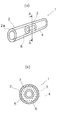
- FIG. 1 (a) and 1 (b) show an embodiment in which the vibration damping structure of the present invention is employed in a rotor shaft, (a) is a perspective view, and (b) is an A in (a).
- FIG. 2 (a) and 2 (b) show different embodiments when the vibration damping structure of the present invention is adopted for a shaft of a rotor, (a) is a perspective view, and (b) is an A of (a).
- 4 (a) and 4 (b) show an embodiment in which the vibration damping structure of the present invention is adopted for a gear, (a) is a front view, and (b) is an AA view of (a). It is line sectional drawing.
- FIG. 1A and 1 (b) show an embodiment in which the vibration damping structure of the present invention is employed in a rotor shaft.
- FIG. 1A is a perspective view
- FIG. 1B is a cross-sectional view taken along the line AA in FIG. 2 (a) and 2 (b) show an embodiment different from that shown in FIGS. 1 (a) and 1 (b) when the vibration damping structure of the present invention is employed in a rotor shaft.
- 2A is a perspective view
- FIG. 2B is a cross-sectional view taken along line AA in FIG. 2A.
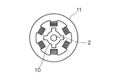
- FIG. 3 is a front view showing an overview of the motor incorporating the stator as viewed from the end face.
- 2 is a shaft
- 10 is a rotor
- 11 is a stator.
- the shaft 2 of the rotor 10 constituting the motor shown in FIG. 1 includes a shaft main body 2a composed of a long cylindrical inner cylinder 3, and an outer cylinder 4 that is mounted around the axial center of the inner cylinder 3. It is configured.
- the outer cylinder 4 is shorter than the inner cylinder 3, and a cylindrical hollow portion 5 is formed between the outer cylinder 4 and the inner cylinder 3. Both end surfaces of the hollow portion 5 are closed by annular end caps 8 provided on both end surfaces of the outer cylinder 4.
- the hollow portion 5 is filled with a plurality of granular bodies 6 and viscoelastic bodies 7 without gaps.
- the granular body 6 is distributed substantially uniformly in the viscoelastic body 7, and the granular body 6 is not biased in the hollow portion 5.
- the granular material 6 is dispersed almost uniformly in the viscoelastic body 7 and filled in the hollow portion 5. For this reason, even if the shaft 2 of the rotor 10 which is the rotating body 1 rotates and the rotational speed becomes high and centrifugal force acts, the granular material 6 is pressed against the inner wall of the hollow portion 5 on the outer peripheral side of the shaft 2 at all. You won't get lost.
- the viscoelastic body 7 oil having a high viscosity (100,000 to 1,000,000 cSt (centistokes) or higher viscosity), liquid rubber, an elastomer whose flow is suppressed by crosslinking, and the like can be used.
- silicone oil, silicone rubber, or silicone gel whose viscoelastic properties (complex elastic modulus) hardly change with temperature is preferably used.
- the material of the granular material 6 is not particularly limited, it is desirable that the granular material 6 is formed from a material mainly composed of iron, aluminum, copper, or ceramic. This is because these materials can be easily obtained, and the granular material 6 can be formed relatively easily.
- the granular material 6 is a non-magnetic material such as a material mainly composed of ceramic, it does not affect the performance of the motor.
- the granular body 6 is a soft magnetic powder such as iron powder or iron-base alloy powder
- the granular body 6 is used when the soft magnetic powder such as iron powder or iron-base alloy powder is used for the compact shaft 2 of the rotor 10.
- the body 6 and the rotor 10 can be formed from the same material, and it is possible to save labor such as material procurement.
- the shape of the granular body 6 is preferably a sphere.
- the hollow portion 5 filled with the plurality of granular bodies 6 and the viscoelastic body 7 is formed not on the rotor 10 body but on the shaft 2 of the rotor 10. The reason is that the shaft 2 is at a position where the magnetic flux density is relatively lower than that of the rotor 10 main body, and therefore the performance of the motor is not impaired even if the hollow portion 5 is formed.
- the shaft 2 of the rotor 10 constituting the motor shown in FIG. 2 includes a shaft main body 2a composed of a long cylindrical outer cylinder 4, and an inner cylinder 3 inserted and fixed at the axial center of the outer cylinder 4. It is configured.
- the inner cylinder 3 is shorter than the outer cylinder 4, and a cylindrical hollow portion 5 is formed between the outer cylinder 4 and the inner cylinder 3. Both end surfaces of the hollow portion 5 are closed by an annular end cap 8 provided between the outer cylinder 4 and the inner cylinder 3.
- the hollow portion 5 is filled with a plurality of granular bodies 6 and viscoelastic bodies 7 without gaps.
- the granular body 6 is dispersed substantially uniformly in the viscoelastic body 7, and the granular body 6 is not biased in the hollow portion 5.
- FIGS. the embodiment in which the lengths of the inner cylinder 3 and the outer cylinder 4 are different from each other is shown in FIGS.
- the hollow portion 5 filled with the plurality of granular bodies 6 and the viscoelastic body 7 is formed over the entire length of the shaft 2 of the rotor 10.
- FIG. 4 (a) and 4 (b) show an embodiment in which the vibration damping structure of the present invention is adopted for a gear.
- 4A is a front view
- FIG. 4B is a cross-sectional view taken along line AA in FIG. 4A.
- the circle formed at substantially equal intervals in the circumferential direction in FIG. 4A is a curved bulge, and the hollow portion 5 is formed inside thereof.
- the gear 9 shown in FIG. 4 is a spur gear having teeth formed on the outer periphery thereof.
- a plurality of hollow portions 5 having substantially the same cross-sectional shape are formed on the entire circumference of the gear 9 so as to be arranged at substantially equal intervals in the circumferential direction.
- the hollow portions 5 are filled with a plurality of granular bodies 6 and viscoelastic bodies 7 without gaps.
- the granular body 6 is dispersed substantially uniformly in the viscoelastic body 7, and the granular body 6 is not biased in the hollow portion 5.
- the granular material 6 is dispersed almost uniformly in the viscoelastic body 7 and filled in the hollow portion 5. For this reason, even if the gear 9 which is the rotating body 1 rotates and the rotational speed becomes high and centrifugal force acts, the granular material 6 is pressed against the inner wall on the outer peripheral side of the gear 9 of the hollow portion 5 and can move at all. There will be no disappearance.
- the granular body 6 and the viscoelastic body 7 are desirably formed of the same materials as those described above in the embodiment in which the vibration damping structure of the present invention is used for the shaft 2 of the rotor 10.
- the mass and volume of the granular body 6 and the viscoelastic body 7 incorporated in the hollow portion 5, the density of the granular body 6 in the viscoelastic body 7, and the shape of each granular body 6 are the same in all the hollow portions 5. It is desirable from the aspect of damping efficiency.
- the damping structure of this invention can be employ
Landscapes
- Engineering & Computer Science (AREA)
- General Engineering & Computer Science (AREA)
- Mechanical Engineering (AREA)
- Ocean & Marine Engineering (AREA)
- Gears, Cams (AREA)
- Shafts, Cranks, Connecting Bars, And Related Bearings (AREA)
- Fluid-Damping Devices (AREA)
Abstract
本発明は、十分な制振作用を得ることができるとともに、温度条件や周波数条件に影響されることなく振動や騒音の発生を抑制することが可能な回転体の制振構造を提供する。本発明に係る回転体1の制振構造においては、回転体1に中空部5が形成されている。中空部5内には複数の粒状体6および粘弾性体7が充填されており、粒状体6は粘弾性体7中に略均等に分散されている。回転体1は、モータを構成するロータ10のシャフト2や、歯車9である。
Description
本発明は、モータに用いられるロータのシャフトや、歯車などの回転体の制振構造に関する。
モータを構成するロータのシャフトや、歯車などの回転体は、その回転時に振動や騒音が発生することがあり、従来から問題になっていた。その原因は、ロータのシャフトの場合には回転時に電磁力の不釣合いが発生することであり、歯車の場合には噛み合い振動が発生することである。この問題を解消するためには、これら回転体に制振材を設けて、制振性を付与することが考えられる。
従来から制振性付与のために用いられている制振材としては、粘弾性材や、粒状体を用いた粒状体衝撃ダンパが挙げられる。ロータのシャフトや、歯車などの回転体にこのような制振材を採用する場合には、回転体に中空部を形成し、その中空部に制振材を内蔵することにより制振作用を得るという方法を採用することが例示できる。
中空部に内蔵する制振材として粘弾性材を採用する場合には、使用する温度や周波数によって粘弾性材の動的特性が変化するという問題がある。その問題を解消するためは、異なる温度特性や周波数特性を持つ粘弾性材をブレンドすることによって、広い温度範囲や周波数範囲に対応できるようにしなければならない。しかしながら、このような対応には限界があり、ロータのシャフトや、歯車などの回転体の制振材として採用するには適切とはいえない。
一方で、特許文献1~3に記載された、粒状体を用いた粒状体衝撃ダンパを制振材として採用することも考えられる。特許文献1に記載された技術は、粒状体を用いて、ターボ流体機械の本体表面、配管、カップリングカバー等からの放射音を効果的に抑制しようとする技術である。特許文献2に記載された技術は、粒状体を用いて、鉄道車両用台車の駆動系のアンバランスに起因する振動を抑制し、振動に伴う車内騒音を低減しようとする技術である。特許文献3に記載された技術は、粒状体を用いて、高い制振性能を有するシート状制振材及び制振パネルを得ようとする技術である。
このように制振材として粒状体を採用する場合は、回転体の中空部に一定の隙間を設けて粒状体を内蔵することになる。しかしながら、回転体の回転数が高くなると、粒状体は遠心力によって中空部の回転体外周側の内壁に押し付けられるようになり、全く運動することができなくなる。従って、前記した特許文献1~3記載のように回転しない構造体の場合には、粒状体同士の衝突や、粒状体と内壁との摩擦によって制振作用が得られるが、回転体の場合には制振作用が得られなくなってしまう。
本発明は、これら従来の問題を解決するためになされたものであり、回転体であっても十分な制振作用を得ることができるとともに、温度条件や周波数条件に影響されることなく、振動や騒音の発生を抑制することが可能な制振構造を提供することを課題とする。
本発明は、中空部が形成された回転体の制振構造であって、前記中空部内には複数の粒状体および粘弾性体が充填されており、前記粒状体は前記粘弾性体中に略均等に分散されていることを特徴とする制振構造である。
本発明において、前記回転体はモータを構成するロータのシャフトであり、前記複数の粒状体および粘弾性体が充填された前記中空部は前記シャフトに形成されていることが好ましい。
前記中空体は、前記シャフトの軸方向中心部のみに形成されていることが好ましい。
前記中空体は、前記シャフトを形成する外筒と内筒との間に形成されていることが好ましい。
または、本発明において、前記回転体は歯車であり、前記複数の粒状体および粘弾性体が充填された前記中空部は前記歯車に形成されていることが好ましい。
前記中空部は、前記歯車の円周方向に略等間隔で形成された、略同一形状の複数の中空部であることが好ましい。
前記中空部に内蔵された粒状体および粘弾性体の質量と体積、並びに前記粘弾性体中の粒状体密度は、全ての中空部において略同一であることが好ましい。
前記粘弾性体は、シリコーンオイル、シリコーンゴム、シリコーンゲルのいずれかであることが好ましい。
本発明の制振構造によれば、回転体が回転すると、中空部内の粒状体はその遠心力によって回転体の外周方向に多少は移動するものの、中空部内には粒状体と共に粘弾性体が充填されているため、粒状体は中空部の内壁に押し付けられることはなくその位置で振動する。その結果、粘弾性体に生じる応力がその粘弾性体中を伝播し、別の粒状体の振動と相互干渉することにより制振性が発揮されるので、回転体であっても十分な制振作用を得ることができる。しかも、温度条件や周波数条件に影響されることなく、振動や騒音の発生を抑制することができる。
本発明の制振構造によると、回転体がモータを構成するロータのシャフトであり、ロータに振動が発生しても、制振作用により振動や騒音の発生を抑制することができる。更には、粒状体と粘弾性体が充填された中空部は、磁束密度が低いロータのシャフトに形成されているため、モータの性能を損なうこともない。
本発明の制振構造によると、粒状体と粘弾性体を充填する中空部を、長いシャフトの軸方向中心部に形成するため、釣り合いがとれ、ロータの回転に悪影響を及ぼすことはない。また、ロータのシャフトの全長にわたり中空部を形成する必要がないため、用いる粒状体と粘弾性体の量を少なくすることができる。
本発明の制振構造によると、粒状体と粘弾性体を充填する中空部を、前記シャフトを形成する外筒と内筒との間に容易に形成することができる。
本発明の制振構造によると、回転体が歯車であり、中空部が歯車に形成されているので、歯車が回転することで発生する振動や騒音を制振作用により抑制することができる。
本発明の制振構造によると、複数の粒状体が内蔵された略同一形状の中空部が歯車の全周に亘り略等間隔に配置されるので、バランス良く確実に、制振作用を発揮することができ、振動や騒音の発生をより確実に抑制することができる。
本発明の制振構造によると、複数の中空部に内蔵された粒状体および粘弾性体の質量と体積、並びに粘弾性体中の粒状体密度は、全ての中空部において略同一であるので、更に確実に制振作用を発揮することができ、振動や騒音の発生を更に確実に抑制することができる。
本発明の制振構造が、温度変化によって粘弾性特性が殆ど変化することのないシリコーンオイル、シリコーンゴム、シリコーンゲルのいずれかを粘弾性体として用いる場合には、温度変化の影響なく確実に制振作用を発揮することができる。
以下、本発明を添付図面に示す実施形態に基づいて更に詳細に説明する。まず、本発明の制振構造をロータのシャフトに採用した実施形態について説明する。
図1(a)および(b)は、本発明の制振構造をロータのシャフトに採用した場合の一実施形態を示す。図1(a)は斜視図であり、図1(b)は図1(a)のA―A線断面図である。図2(a)および(b)は、本発明の制振構造をロータのシャフトに採用した場合の、図1(a)および(b)とは異なる実施形態を示す。図2(a)は斜視図であり、図2(b)は図2(a)のA―A線断面図である。
また、図3は、ステータを組み込んだモータを端面から見た概要を示す正面図である。2がシャフト、10がロータ、11がステータを示す。
図1に示すモータを構成するロータ10のシャフト2は、長尺円筒状の内筒3からなるシャフト本体2aと、その内筒3の軸方向中心部に環装された外筒4と、から構成されている。外筒4は内筒3より短く、外筒4と内筒3の間には円筒状の中空部5が形成されている。中空部5の両端面は、外筒4の両端面に設けられた円環状の端部キャップ8で閉塞されている。この中空部5内には、複数の粒状体6および粘弾性体7が隙間なく充填されている。粒状体6は粘弾性体7中に略均等に分散されており、中空部5内において粒状体6の偏りはない。
このように、粒状体6は、粘弾性体7中に略均等に分散されて中空部5内に充填されている。このため、回転体1であるロータ10のシャフト2が回転し、回転数が高くなって遠心力が作用しても、粒状体6が中空部5のシャフト2外周側の内壁に押し付けられて全く運動できなくなるようなことはない。
ロータ10のシャフト2が回転すると、その遠心力によって、粒状体6は静止状態よりシャフト2の外周方向に多少は移動するものの、その振動が抑制されるわけではない。粒状体6が振動することで粘弾性体7に生じる応力は粘弾性体7中を伝播し、別の粒状体6の振動と相互干渉することにより制振性が発揮される。
この粘弾性体7としては、高粘度(100,000~1,000,000cSt(centistokes)あるいはそれ以上の粘度)のオイルや、液状ゴム、架橋させて流動を抑えたエラストマ等が採用できる。それらの中でも、粘弾性特性(複素弾性率)が温度により殆ど変化しないシリコーンオイル、シリコーンゴム、シリコーンゲルのいずれかが好適に用いられる。更には、-50℃でも硬化しない耐寒性ゲルを用いることが最適である。すなわち、粘弾性体7は、耐熱性が高く、温度・周波数依存性が低いことが望ましい。また、弾性係数を調整するために、粘弾性体中に多数の気泡を設けても良い。
また、粒状体6は、特にその材質は限定されないが、鉄、アルミ、銅、セラミックのいずれかを主成分とする材料から形成されていることが望ましい。これは、これらの材料は容易に得ることができ、粒状体6の形成も比較的容易にできるためである。
粒状体6がセラミックを主成分とする材料等の非磁性材である場合は、モータの性能に影響を及ぼすことがない。一方、粒状体6が鉄粉や鉄基合金粉末等の軟磁性粉末である場合は、鉄粉や鉄基合金粉末等の軟磁性粉末を圧粉成形したロータ10のシャフト2に用いる場合、粒状体6とロータ10を同一材料から形成することができ、材料調達等の手間を省くことも可能になる。また、粒状体6の形状は球体であることが望ましい。
尚、複数の粒状体6および粘弾性体7を充填した中空部5は、ロータ10本体でなく、ロータ10のシャフト2に形成される。その理由は、ロータ10本体に比べてシャフト2は磁束密度が比較的低い位置であるため、中空部5を形成してもモータの性能を損なうことがないためである。
図2に示すモータを構成するロータ10のシャフト2は、長尺円筒状の外筒4からなるシャフト本体2aと、その外筒4の軸方向中心部に挿入固定された内筒3と、から構成されている。内筒3は外筒4より短く、外筒4と内筒3の間には円筒状の中空部5が形成されている。中空部5の両端面は、外筒4と内筒3との間に設けられた円環状の端部キャップ8で閉塞されている。この中空部5内には、複数の粒状体6および粘弾性体7が隙間なく充填されている。粒状体6は粘弾性体7中に略均等に分散されており、中空部5内において粒状体6の偏りはない。
この図2に示す実施形態で得られる作用、およびその他の構成については、図1に示す実施形態と同様である。
以上、図1および図2により内筒3と外筒4の長さが異なる実施形態を示したが、内筒3と外筒4が共に同一長さの長尺であっても良い。この場合、複数の粒状体6と粘弾性体7が充填される中空部5は、ロータ10のシャフト2全長に亘って形成されることになる。
次に、本発明の制振構造を歯車に採用した実施形態について説明する。
図4(a)および(b)は、本発明の制振構造を歯車に採用した場合の一実施形態を示す。図4(a)は正面図であり、図4(b)は図4(a)のA-A線断面図である。尚、図4(a)の円周方向に略等間隔で形成された円形は曲面状の隆起であり、その内側に中空部5が形成されている。
図4に示す歯車9は、その外周に歯が形成された平歯車である。この歯車9の全周には、円周方向に略等間隔に並べて略同一断面形状の複数の中空部5が形成されている。それら中空部5内には、複数の粒状体6および粘弾性体7が隙間なく充填されている。粒状体6は粘弾性体7中に略均等に分散されており、中空部5内において粒状体6の偏りはない。
このように、粒状体6は、粘弾性体7中に略均等に分散されて中空部5内に充填されている。このため、回転体1である歯車9が回転し、回転数が高くなって遠心力が作用しても、粒状体6が中空部5の歯車9の外周側の内壁に押し付けられて全く運動できなくなるようなことはない。
歯車9が回転すると、その遠心力によって、粒状体6は静止状態より歯車9の外周方向に多少は移動するものの、その振動が抑制されるわけではない。粒状体6が振動することで粘弾性体7に生じる応力は粘弾性体7中を伝播し、別の粒状体6の振動と相互干渉することにより制振性が発揮される。
尚、粒状体6および粘弾性体7は、本発明の制振構造をロータ10のシャフト2に採用した実施形態において先に説明した材料と同様の材料で形成されていることが望ましい。
また、中空部5に内蔵された粒状体6および粘弾性体7の質量と体積、粘弾性体7中の粒状体6の密度、並びに各粒状体6の形状は、全ての中空部5において同一であることが、制振効率の面から望ましい。
尚、歯車9が平歯車である事例を用いて説明したが、本発明の制振構造が、はす歯歯車、山歯歯車、かさ歯車等、および他の歯車においても採用できることは勿論である。
以上のとおり、本発明を詳細に、また特定の実施態様を参照して説明したが、本発明の精神と範囲を逸脱することなく様々な変更や修正を加えることができることは当業者にとって明らかである。本出願は2008年10月7日出願の日本特許出願(特願2008-260725)に基づくものであり、その内容はここに参照として取り込まれる。
1…回転体
2…シャフト
2a…シャフト本体
3…内筒
4…外筒
5…中空部
6…粒状体
7…粘弾性体
8…端部キャップ
9…歯車
10…ロータ
11…ステータ
2…シャフト
2a…シャフト本体
3…内筒
4…外筒
5…中空部
6…粒状体
7…粘弾性体
8…端部キャップ
9…歯車
10…ロータ
11…ステータ
Claims (8)
- 中空部が形成された回転体の制振構造であって、
前記中空部内には複数の粒状体および粘弾性体が充填されており、前記粒状体は前記粘弾性体中に略均等に分散されていることを特徴とする制振構造。 - 前記回転体はモータを構成するロータのシャフトであり、前記複数の粒状体および粘弾性体が充填された前記中空部は前記シャフトに形成されていることを特徴とする請求項1記載の制振構造。
- 前記中空部は、前記シャフトの軸方向中心部のみに形成されていることを特徴とする請求項2記載の制振構造。
- 前記中空部は、前記シャフトを形成する外筒と内筒との間に形成されていることを特徴とする請求項2記載の制振構造。
- 前記回転体は歯車であり、前記複数の粒状体および粘弾性体が充填された前記中空部は前記歯車に形成されていることを特徴とする請求項1記載の制振構造。
- 前記中空部は、前記歯車の円周方向に略等間隔で形成された、略同一形状の複数の中空部であることを特徴とする請求項5記載の制振構造。
- 前記中空部に内蔵された粒状体および粘弾性体の質量と体積、並びに前記粘弾性体中の粒状体密度は、全ての中空部において略同一であることを特徴とする請求項6記載の制振構造。
- 前記粘弾性体は、シリコーンオイル、シリコーンゴム、シリコーンゲルのいずれかであることを特徴とする請求項1~7のいずれかに記載の制振構造。
Applications Claiming Priority (2)
| Application Number | Priority Date | Filing Date | Title |
|---|---|---|---|
| JP2008-260725 | 2008-10-07 | ||
| JP2008260725A JP2010090966A (ja) | 2008-10-07 | 2008-10-07 | 制振構造 |
Publications (1)
| Publication Number | Publication Date |
|---|---|
| WO2010041671A1 true WO2010041671A1 (ja) | 2010-04-15 |
Family
ID=42100621
Family Applications (1)
| Application Number | Title | Priority Date | Filing Date |
|---|---|---|---|
| PCT/JP2009/067436 Ceased WO2010041671A1 (ja) | 2008-10-07 | 2009-10-06 | 制振構造 |
Country Status (2)
| Country | Link |
|---|---|
| JP (1) | JP2010090966A (ja) |
| WO (1) | WO2010041671A1 (ja) |
Families Citing this family (6)
| Publication number | Priority date | Publication date | Assignee | Title |
|---|---|---|---|---|
| CN102052387A (zh) * | 2011-01-07 | 2011-05-11 | 富奥汽车零部件股份有限公司 | 一种传动轴总成减振结构 |
| JP5945218B2 (ja) * | 2012-11-30 | 2016-07-05 | 公益財団法人鉄道総合技術研究所 | 制振装置及び鉄道車両 |
| CN104295707A (zh) * | 2014-09-15 | 2015-01-21 | 常州市耀华仪器有限公司 | 防护型减速机齿轮 |
| US9975376B2 (en) * | 2015-12-21 | 2018-05-22 | Goodrich Corporation | Axle damper insert |
| JP6944400B2 (ja) * | 2018-03-05 | 2021-10-06 | 住友重機械工業株式会社 | 減速装置 |
| JP2020112239A (ja) * | 2019-01-15 | 2020-07-27 | 株式会社デンソー | ピニオンギア及び始動装置 |
Citations (5)
| Publication number | Priority date | Publication date | Assignee | Title |
|---|---|---|---|---|
| JPH01149056U (ja) * | 1988-04-05 | 1989-10-16 | ||
| JPH11223246A (ja) * | 1998-02-05 | 1999-08-17 | Unisia Jecs Corp | ロータリダンパ |
| JP2001206221A (ja) * | 2000-01-27 | 2001-07-31 | Hitachi Ltd | 鉄道車両 |
| JP2006500533A (ja) * | 2002-09-27 | 2006-01-05 | リカルド ユーケー リミテッド | 捩り減衰回転シャフト |
| JP6052984B2 (ja) * | 2011-12-27 | 2016-12-27 | 日本酢ビ・ポバール株式会社 | 電解コンデンサの駆動用電解液 |
-
2008
- 2008-10-07 JP JP2008260725A patent/JP2010090966A/ja active Pending
-
2009
- 2009-10-06 WO PCT/JP2009/067436 patent/WO2010041671A1/ja not_active Ceased
Patent Citations (5)
| Publication number | Priority date | Publication date | Assignee | Title |
|---|---|---|---|---|
| JPH01149056U (ja) * | 1988-04-05 | 1989-10-16 | ||
| JPH11223246A (ja) * | 1998-02-05 | 1999-08-17 | Unisia Jecs Corp | ロータリダンパ |
| JP2001206221A (ja) * | 2000-01-27 | 2001-07-31 | Hitachi Ltd | 鉄道車両 |
| JP2006500533A (ja) * | 2002-09-27 | 2006-01-05 | リカルド ユーケー リミテッド | 捩り減衰回転シャフト |
| JP6052984B2 (ja) * | 2011-12-27 | 2016-12-27 | 日本酢ビ・ポバール株式会社 | 電解コンデンサの駆動用電解液 |
Also Published As
| Publication number | Publication date |
|---|---|
| JP2010090966A (ja) | 2010-04-22 |
Similar Documents
| Publication | Publication Date | Title |
|---|---|---|
| WO2010041671A1 (ja) | 制振構造 | |
| CN107676428B (zh) | 内燃机的平衡装置 | |
| CN105042030B (zh) | 用于无游隙的传动级的齿轮以及配设有所述齿轮的传动级 | |
| CN103851127B (zh) | 用于飞轮的阻尼的装置 | |
| JP6725064B2 (ja) | 軸受構造および電動コンプレッサ | |
| JP6773803B2 (ja) | ダイナミックダンパ | |
| CN111630298A (zh) | 具有包括第一摩擦装置的离心力摆装置的皮带轮脱耦器 | |
| TW201842282A (zh) | 扭轉振動衰減裝置 | |
| JP2010090967A (ja) | 制振構造 | |
| CN107110234A (zh) | 用于摩托车的离合器装置以及扭矩传递装置或者离合器 | |
| CN108561503A (zh) | 含负刚度弹簧动力吸振单元及推力轴承 | |
| JP2007182986A (ja) | 振動低減ダンパ | |
| JP7088312B2 (ja) | 渦電流式ダンパ | |
| JP7103266B2 (ja) | 回転力伝達機構 | |
| JP2005519245A (ja) | 騒音低減機械部品 | |
| JP2007315416A (ja) | ビスカスラバーダンパー | |
| JP7101556B2 (ja) | 渦電流式ダンパ | |
| JP5863038B2 (ja) | フリクションダンパ | |
| KR101978483B1 (ko) | 베어링 진동 저감 장치 및 이를 포함하는 진동저감 베어링 | |
| JP6936051B2 (ja) | ダイナミックダンパ | |
| JP2010196815A (ja) | ダイナミックダンパ | |
| JP3631902B2 (ja) | 振動低減ダンパ | |
| JP2791769B2 (ja) | 粒子式トーシヨナルダンパ | |
| KR20180093698A (ko) | 비스코스 댐퍼 | |
| JP2009133396A (ja) | プーリ構造体 |
Legal Events
| Date | Code | Title | Description |
|---|---|---|---|
| 121 | Ep: the epo has been informed by wipo that ep was designated in this application |
Ref document number: 09819205 Country of ref document: EP Kind code of ref document: A1 |
|
| NENP | Non-entry into the national phase |
Ref country code: DE |
|
| 122 | Ep: pct application non-entry in european phase |
Ref document number: 09819205 Country of ref document: EP Kind code of ref document: A1 |