WO2010038569A1 - 熱交換器および温水システム - Google Patents
熱交換器および温水システム Download PDFInfo
- Publication number
- WO2010038569A1 WO2010038569A1 PCT/JP2009/065166 JP2009065166W WO2010038569A1 WO 2010038569 A1 WO2010038569 A1 WO 2010038569A1 JP 2009065166 W JP2009065166 W JP 2009065166W WO 2010038569 A1 WO2010038569 A1 WO 2010038569A1
- Authority
- WO
- WIPO (PCT)
- Prior art keywords
- hot water
- pressure refrigerant
- pipe
- low
- heat exchanger
- Prior art date
- Legal status (The legal status is an assumption and is not a legal conclusion. Google has not performed a legal analysis and makes no representation as to the accuracy of the status listed.)
- Ceased
Links
Images


Classifications
-
- F—MECHANICAL ENGINEERING; LIGHTING; HEATING; WEAPONS; BLASTING
- F25—REFRIGERATION OR COOLING; COMBINED HEATING AND REFRIGERATION SYSTEMS; HEAT PUMP SYSTEMS; MANUFACTURE OR STORAGE OF ICE; LIQUEFACTION SOLIDIFICATION OF GASES
- F25B—REFRIGERATION MACHINES, PLANTS OR SYSTEMS; COMBINED HEATING AND REFRIGERATION SYSTEMS; HEAT PUMP SYSTEMS
- F25B40/00—Subcoolers, desuperheaters or superheaters
-
- F—MECHANICAL ENGINEERING; LIGHTING; HEATING; WEAPONS; BLASTING
- F24—HEATING; RANGES; VENTILATING
- F24D—DOMESTIC- OR SPACE-HEATING SYSTEMS, e.g. CENTRAL HEATING SYSTEMS; DOMESTIC HOT-WATER SUPPLY SYSTEMS; ELEMENTS OR COMPONENTS THEREFOR
- F24D11/00—Central heating systems using heat accumulated in storage masses
- F24D11/02—Central heating systems using heat accumulated in storage masses using heat pumps
- F24D11/0214—Central heating systems using heat accumulated in storage masses using heat pumps water heating system
-
- F—MECHANICAL ENGINEERING; LIGHTING; HEATING; WEAPONS; BLASTING
- F28—HEAT EXCHANGE IN GENERAL
- F28D—HEAT-EXCHANGE APPARATUS, NOT PROVIDED FOR IN ANOTHER SUBCLASS, IN WHICH THE HEAT-EXCHANGE MEDIA DO NOT COME INTO DIRECT CONTACT
- F28D7/00—Heat-exchange apparatus having stationary tubular conduit assemblies for both heat-exchange media, the media being in contact with different sides of a conduit wall
- F28D7/0066—Multi-circuit heat-exchangers, e.g. integrating different heat exchange sections in the same unit or heat-exchangers for more than two fluids
-
- F—MECHANICAL ENGINEERING; LIGHTING; HEATING; WEAPONS; BLASTING
- F28—HEAT EXCHANGE IN GENERAL
- F28D—HEAT-EXCHANGE APPARATUS, NOT PROVIDED FOR IN ANOTHER SUBCLASS, IN WHICH THE HEAT-EXCHANGE MEDIA DO NOT COME INTO DIRECT CONTACT
- F28D7/00—Heat-exchange apparatus having stationary tubular conduit assemblies for both heat-exchange media, the media being in contact with different sides of a conduit wall
- F28D7/10—Heat-exchange apparatus having stationary tubular conduit assemblies for both heat-exchange media, the media being in contact with different sides of a conduit wall the conduits being arranged one within the other, e.g. concentrically
- F28D7/103—Heat-exchange apparatus having stationary tubular conduit assemblies for both heat-exchange media, the media being in contact with different sides of a conduit wall the conduits being arranged one within the other, e.g. concentrically consisting of more than two coaxial conduits or modules of more than two coaxial conduits
-
- F—MECHANICAL ENGINEERING; LIGHTING; HEATING; WEAPONS; BLASTING
- F25—REFRIGERATION OR COOLING; COMBINED HEATING AND REFRIGERATION SYSTEMS; HEAT PUMP SYSTEMS; MANUFACTURE OR STORAGE OF ICE; LIQUEFACTION SOLIDIFICATION OF GASES
- F25B—REFRIGERATION MACHINES, PLANTS OR SYSTEMS; COMBINED HEATING AND REFRIGERATION SYSTEMS; HEAT PUMP SYSTEMS
- F25B2309/00—Gas cycle refrigeration machines
- F25B2309/06—Compression machines, plants or systems characterised by the refrigerant being carbon dioxide
- F25B2309/061—Compression machines, plants or systems characterised by the refrigerant being carbon dioxide with cycle highest pressure above the supercritical pressure
-
- F—MECHANICAL ENGINEERING; LIGHTING; HEATING; WEAPONS; BLASTING
- F28—HEAT EXCHANGE IN GENERAL
- F28D—HEAT-EXCHANGE APPARATUS, NOT PROVIDED FOR IN ANOTHER SUBCLASS, IN WHICH THE HEAT-EXCHANGE MEDIA DO NOT COME INTO DIRECT CONTACT
- F28D7/00—Heat-exchange apparatus having stationary tubular conduit assemblies for both heat-exchange media, the media being in contact with different sides of a conduit wall
- F28D7/0008—Heat-exchange apparatus having stationary tubular conduit assemblies for both heat-exchange media, the media being in contact with different sides of a conduit wall the conduits for one medium being in heat conductive contact with the conduits for the other medium
- F28D7/0016—Heat-exchange apparatus having stationary tubular conduit assemblies for both heat-exchange media, the media being in contact with different sides of a conduit wall the conduits for one medium being in heat conductive contact with the conduits for the other medium the conduits for one medium or the conduits for both media being bent
-
- F—MECHANICAL ENGINEERING; LIGHTING; HEATING; WEAPONS; BLASTING
- F28—HEAT EXCHANGE IN GENERAL
- F28D—HEAT-EXCHANGE APPARATUS, NOT PROVIDED FOR IN ANOTHER SUBCLASS, IN WHICH THE HEAT-EXCHANGE MEDIA DO NOT COME INTO DIRECT CONTACT
- F28D7/00—Heat-exchange apparatus having stationary tubular conduit assemblies for both heat-exchange media, the media being in contact with different sides of a conduit wall
- F28D7/10—Heat-exchange apparatus having stationary tubular conduit assemblies for both heat-exchange media, the media being in contact with different sides of a conduit wall the conduits being arranged one within the other, e.g. concentrically
- F28D7/106—Heat-exchange apparatus having stationary tubular conduit assemblies for both heat-exchange media, the media being in contact with different sides of a conduit wall the conduits being arranged one within the other, e.g. concentrically consisting of two coaxial conduits or modules of two coaxial conduits
Definitions
- the present invention relates to a heat exchanger and a hot water system such as a hot water supply device or a heating hot water supply device.
- Patent Document 1 JP 2008-82600 A
- This water heater is equipped with a heat pump unit that boils hot water.
- the refrigerant circuit of this heat pump unit is provided with a water refrigerant heat exchanger, and cold water such as tap water (hereinafter referred to as “cold water”) is heated through the water refrigerant heat exchanger to become hot water. .
- the water refrigerant heat exchanger is composed of an outer tube and an inner tube accommodated in the outer tube. Cold water flows between the inner wall of the outer tube and the outer wall of the inner tube. On the other hand, the refrigerant that has been compressed by the compressor and has reached a high temperature flows into the inner pipe. Thereby, the heat of the said refrigerant
- coolant can be transmitted to cold water, and cold water can be boiled.
- the conventional hot water supply device it is necessary for the conventional hot water supply device to perform the defrost operation in a state where the circulation of the cold water is stopped. That is, the conventional hot water supply apparatus cannot boil cold water during the defrost operation.
- This heating and hot water supply apparatus includes a heat pump unit, a hot water storage tank, and a heating terminal.
- the heat pump unit includes a fan, a first evaporator, a second evaporator, a compressor, a condenser, and an expansion valve.
- the first evaporator receives outside air from the fan and takes in heat from the outside air.
- the first evaporator is located on the upstream side of the compressor and on the downstream side of the second evaporator. That is, the refrigerant exiting the second evaporator flows into the compressor after passing through the first evaporator.
- the heating / hot water supply apparatus configured as described above, while the water in the hot water storage tank is being boiled by the heat pump unit, the hot water in the hot water storage tank is sent to the second evaporator by the pump. Thereby, since the refrigerant
- the conventional heating and hot water supply apparatus has a problem that the refrigerant entering the first evaporator cannot be supercooled because the heat pump unit does not include the supercooling heat exchanger.
- an object of the present invention is to provide a heat exchanger that can improve the COP of a heat pump unit, for example, can supercool a high-pressure refrigerant, and can further increase the efficiency of the heat pump unit, for example. It is in.
- Another object of the present invention is to provide a hot water system provided with the heat exchanger.
- the heat exchanger of the present invention is Water piping through which water flows, A low-pressure refrigerant pipe that is arranged inside the water pipe and through which the low-pressure refrigerant flows; A high-pressure refrigerant pipe that is arranged inside the low-pressure refrigerant pipe and through which the high-pressure refrigerant flows,
- the low-pressure refrigerant pipe is arranged to be able to exchange heat with the water pipe and the high-pressure refrigerant pipe.
- the low-pressure refrigerant pipe is arranged so as to be capable of exchanging heat with the water pipe and the high-pressure refrigerant pipe. Therefore, by providing the heat exchanger, for example, in the refrigerant circuit of the heat pump unit, the temperature of the low-pressure refrigerant entering, for example, the evaporator of the heat pump unit can be increased, and the frost of the evaporator can be melted.
- the water can be heated by supplying water to, for example, the condenser of the heat pump unit.
- the water flowing through the water pipe is absorbed by the low-pressure refrigerant flowing through the low-pressure refrigerant pipe, and the temperature drops. Therefore, the COP of the heat pump unit can be improved by supplying the water whose temperature has been lowered through the water pipe to the condenser of the heat pump unit, for example.
- the low-pressure refrigerant pipe is arranged so as to be able to exchange heat with the high-pressure refrigerant pipe, the heat of the high-pressure refrigerant is absorbed by the low-pressure refrigerant, so that the high-pressure refrigerant can be supercooled.
- the heat exchanger when used in, for example, a heat pump unit, the heat exchanger can supercool the high-pressure refrigerant, so that it is not necessary to install a supercooling heat exchanger separately from the heat exchanger. Therefore, since the number of heat exchangers of the heat pump unit can be reduced and the pressure loss of the refrigerant circuit can be reduced, the efficiency of the heat pump unit can be increased.
- Patent Document 2 In order to perform supercooling of the high-pressure refrigerant in the conventional heating and hot water supply apparatus (Patent Document 2), a supercooling heat exchanger is installed separately from the defrosting heat exchanger (second evaporator). As a result, the number of heat exchangers increases. For this reason, the pressure loss of the said refrigerant circuit becomes large, and will reduce the efficiency of a heat pump unit.
- the high-pressure refrigerant pipe is disposed inside the water pipe and the low-pressure refrigerant pipe, the diameter of the high-pressure refrigerant pipe can be reduced and the high-pressure refrigerant pipe can be thinned.
- the low-pressure refrigerant pipe and the high-pressure refrigerant pipe inserted into the low-pressure refrigerant pipe form a double pipe structure.
- the low-pressure refrigerant pipe and the high-pressure refrigerant pipe have a double pipe structure, the low-pressure refrigerant directly contacts the high-pressure refrigerant pipe, and the heat of the high-pressure refrigerant is converted into the low-pressure refrigerant.
- the efficiency of transmission can be improved.
- the water pipe is wound around the low-pressure refrigerant pipe.
- the manufacturing can be simplified.
- the flow passage cross-sectional area of the low-pressure refrigerant pipe is larger than the flow passage cross-sectional area of the water pipe and larger than the flow passage cross-sectional area of the high-pressure refrigerant pipe.
- the pipe cross-sectional area of the low-pressure refrigerant pipe is larger than the pipe cross-sectional area of the water pipe and larger than the pipe cross-sectional area of the high-pressure refrigerant pipe, the pressure loss of the low-pressure refrigerant Can be kept low. Therefore, when the heat exchanger is used in, for example, a heat pump unit, the efficiency of the heat pump unit can be further increased.
- the hot water system of the present invention is A heat pump unit having the heat exchanger of the present invention; A hot water storage tank for storing hot water heated by the heat pump unit, The hot water in the hot water storage tank heats the low-pressure refrigerant through the water pipe.
- the hot water in the hot water storage tank heats the low-pressure refrigerant through the water pipe, the temperature of the low-pressure refrigerant entering, for example, the evaporator of the heat pump unit rises, and the evaporator frost is removed. Can be melted. That is, the defrosting operation can be performed by the warm water flowing through the water pipe.
- the hot water in the hot water storage tank can be supplied to the water piping, so defrost operation is performed while boiling the hot water in the hot water storage tank. Can do.
- the hot water in the hot water storage tank is cooled through the water pipe and the temperature is lowered. Therefore, the COP of the heat pump unit can be improved by sending warm water whose temperature has decreased through the water pipe to, for example, a condenser of the heat pump unit.
- the heat of the high-pressure refrigerant is absorbed by the low-pressure refrigerant because the low-pressure refrigerant pipe is arranged so as to be able to exchange heat with the high-pressure refrigerant pipe, so that the high-pressure refrigerant can be supercooled. .
- the heat exchanger can supercool the high-pressure refrigerant, the number of heat exchangers in the heat pump unit can be reduced, and the pressure loss in the refrigerant circuit can be reduced. As a result, the efficiency of the heat pump unit can be increased.
- the high-pressure refrigerant pipe is disposed inside the water pipe and the low-pressure refrigerant pipe, the diameter of the high-pressure refrigerant pipe can be reduced and the high-pressure refrigerant pipe can be thinned.
- the heat pump unit includes a refrigerant circuit including the high-pressure refrigerant pipe and the low-pressure refrigerant pipe, and an evaporator, a compressor, a condenser, and an expansion mechanism provided in the refrigerant circuit
- the low-pressure refrigerant pipe is a pipe that guides the low-pressure refrigerant that has exited the expansion mechanism to the compressor
- the high-pressure refrigerant pipe is a pipe that guides the refrigerant exiting the compressor to the expansion mechanism.
- the low-pressure refrigerant pipe is a pipe that guides the low-pressure refrigerant that has exited the expansion mechanism to the compressor, so that the temperature of the refrigerant entering the compressor can be increased.
- the high-pressure refrigerant pipe is a pipe for guiding the high-pressure refrigerant that has exited the compressor to the expansion mechanism, the temperature of the refrigerant entering the expansion mechanism can be lowered.
- the heat pump unit uses a CO 2 refrigerant.
- the heat pump unit uses a CO 2 refrigerant, so that the heat pump unit can perform hot hot water discharge.
- the low-pressure refrigerant is arranged so that heat exchange is possible with the water pipe and the high-pressure refrigerant pipe. Since the temperature of the low-pressure refrigerant is increased by absorption, the temperature of the low-pressure refrigerant entering, for example, the evaporator of the heat pump unit can be increased to melt the frost of the evaporator.
- the water can be heated by supplying water to, for example, the condenser of the heat pump unit.
- the COP of the heat pump unit is improved by supplying this low-temperature water to, for example, the condenser of the heat pump unit. Can do.
- the low-pressure refrigerant pipe is arranged so as to be able to exchange heat with the high-pressure refrigerant pipe, the heat of the high-pressure refrigerant is absorbed by the low-pressure refrigerant, so that the high-pressure refrigerant can be supercooled.
- the heat exchanger when used in, for example, a heat pump unit, the heat exchanger can supercool the high-pressure refrigerant, so that it is not necessary to install a supercooling heat exchanger separately from the heat exchanger. Therefore, since the number of heat exchangers of the heat pump unit can be reduced and the pressure loss of the refrigerant circuit can be reduced, the efficiency of the heat pump unit can be increased.
- the high-pressure refrigerant pipe is disposed inside the water pipe and the low-pressure refrigerant pipe, the diameter of the high-pressure refrigerant pipe can be reduced and the high-pressure refrigerant pipe can be thinned.
- the hot water in the hot water storage tank heats the low-pressure refrigerant through the water pipe, the temperature of the low-pressure refrigerant entering, for example, the evaporator of the heat pump unit can be increased and the defrost operation can be performed. .
- the hot water in the hot water storage tank can be supplied to the water pipe, so that the defrosting operation can be performed while performing the boiling operation. .
- the COP of the heat pump unit can be improved by sending this low temperature hot water to, for example, a condenser of the heat pump unit.
- the heat of the high-pressure refrigerant is absorbed by the low-pressure refrigerant because the low-pressure refrigerant pipe is arranged so as to be able to exchange heat with the high-pressure refrigerant pipe. It can be carried out.
- the heat exchanger can supercool the high-pressure refrigerant, the number of heat exchangers in the heat pump unit can be reduced, the pressure loss in the refrigerant circuit can be reduced, and as a result, the efficiency of the heat pump unit can be increased.
- the high-pressure refrigerant pipe is disposed inside the water pipe and the low-pressure refrigerant pipe, the diameter of the high-pressure refrigerant pipe can be reduced and the high-pressure refrigerant pipe can be thinned.
- FIG. 1 is a schematic diagram of a heating and hot water supply apparatus according to a first embodiment of the present invention.
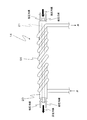
- FIG. 2 is a schematic diagram of the defrost heat exchanger according to the first embodiment of the present invention.
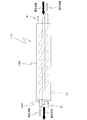
- FIG. 3 is a schematic view of a defrost heat exchanger according to a second embodiment of the present invention.
- FIG. 4 is a schematic view of a defrost heat exchanger according to a third embodiment of the present invention.
- Drawing 1 is a mimetic diagram showing composition of a heating hot-water supply device of a 1st embodiment of the present invention.
- the heating / hot water supply apparatus includes a heat pump unit 1, a hot water storage tank 2, a hot water supply heat exchanger 3, a heating circulation circuit 4, a boiling circulation circuit 5, and a defrost circulation circuit 50.
- the heat pump unit 1 includes a refrigerant circuit 16 and an electric blower 17 and boiles water in the hot water storage tank 2 to make warm water.
- the heat pump unit 1 is connected to a hot water storage tank 2 via a boiling circulation circuit 5.
- the refrigerant circuit 16 includes an evaporator 11, a compressor 12, a condenser 13, a defrost heat exchanger 14, an expansion valve 15, a low-pressure refrigerant pipe 20, and a high-pressure refrigerant pipe 21.
- CO 2 refrigerant circulates.
- the expansion valve 15 is an example of an expansion mechanism
- the defrost heat exchanger 14 is an example of a heat exchanger.
- the low-pressure refrigerant pipe 20 is a pipe that guides the low-pressure CO 2 refrigerant that has exited the expansion valve 15 to the compressor 12. This low-pressure CO 2 refrigerant passes through the evaporator 11 and the defrost heat exchanger 14 in this order from the expansion valve 15 to the compressor 12.
- the high-pressure refrigerant pipe 21 is a pipe that guides the high-pressure CO 2 refrigerant that has exited the compressor 12 to the expansion valve 15. This high-pressure CO 2 refrigerant passes through the condenser 13 and the defrost heat exchanger 14 in this order from the compressor 12 to the expansion valve 15.
- the defrost heat exchanger 14 is connected to the hot water storage tank 2 via a defrost circulation circuit 50. Thereby, the hot water in the hot water storage tank 2 can be supplied to the defrost heat exchanger 14 through the water pipe 56 of the defrost circulation circuit 50.
- FIG. 2 is a diagram schematically showing the structure of the defrost heat exchanger 14.
- the high-pressure refrigerant pipe 21 is inserted into the low-pressure refrigerant pipe 20, and the low-pressure refrigerant pipe 20 and the high-pressure refrigerant pipe 21 form a double pipe structure.
- the inner diameter of the low-pressure refrigerant pipe 20 is larger than the outer diameter of the high-pressure refrigerant pipe 21, and low-pressure CO 2 refrigerant flows between the inner wall of the low-pressure refrigerant pipe 20 and the outer wall of the high-pressure refrigerant pipe 21.
- the high-pressure CO 2 refrigerant flows through the space in the low-pressure refrigerant pipe 20.
- a water pipe 56 is spirally wound around a substantially linear portion of the low-pressure refrigerant pipe 20, and the part and the water pipe 56 are in thermal contact with each other.
- the flow passage cross-sectional area of the low-pressure refrigerant pipe 20 is larger than the flow passage cross-sectional area of the water pipe 56 and larger than the flow passage cross-sectional area of the high-pressure refrigerant pipe 21.
- the low-pressure CO 2 refrigerant entering the evaporator 11 absorbs heat in the air sent from the electric blower 17 and rises in temperature.
- the low-pressure CO 2 refrigerant flows through the low-pressure refrigerant pipe 20 and reaches the defrost heat exchanger 14.
- the defrost heat exchanger 14 the low-pressure CO 2 refrigerant absorbs the heat of the high-pressure CO 2 refrigerant in the high-pressure refrigerant pipe 21 and the temperature further increases.
- the low-pressure CO 2 refrigerant is compressed by the compressor 12 to become a high-pressure CO 2 refrigerant, and the temperature further increases.
- This high-pressure CO 2 refrigerant releases heat at the condenser 13 and becomes low temperature, and then reaches the defrost heat exchanger 14 through the guidance of the high-pressure refrigerant pipe 21.
- CO 2 refrigerant pressure is absorbed heat to the CO 2 refrigerant low pressure in the low-pressure refrigerant pipe 20, the temperature further lowers.
- the high-pressure CO 2 refrigerant whose temperature has further decreased is reduced in pressure by the expansion valve 15 and then returned to the evaporator 11.
- the hot water in the hot water storage tank 2 is supplied to the defrost heat exchanger 14 through the water pipe 56 of the defrost circulation circuit 50. Accordingly, during the defrost operation, in the defrost heat exchanger 14, the low-pressure CO 2 refrigerant in the low-pressure refrigerant pipe 20 is the heat of the hot water in the water pipe 56 and the high-pressure CO 2 refrigerant in the high-pressure refrigerant pipe 21. Absorbs heat and rises in temperature.
- the defrost heat exchanger 14 since the defrost heat exchanger 14 is not supplied with hot water from the hot water storage tank 2 during non-defrost operation, the defrost heat exchanger 14 does not perform heat exchange between the hot water and the low-pressure CO 2 refrigerant.
- the defrost circuit 50 has a branch valve 55 and a water pipe 56.
- the branch valve 55 has an inlet through which hot water from the hot water storage tank 2 flows and two outlets through which hot water flows out. Of these two outlets, one outlet is connected to the condenser 13, and the other outlet is connected to the defrost heat exchanger 14 via a water pipe 56.
- the amount of warm water entering the condenser 13 can be adjusted by adjusting the opening degree of the one outlet. Further, the amount of hot water entering the defrost heat exchanger 14 can be adjusted by adjusting the opening degree of the other outlet.
- the opening degree of each outlet of the branch valve 7 is adjusted by the control unit 7.
- the boiling circulation circuit 5 is provided with a boiling circulation pump 51 and a boiling three-way valve 52.
- the boiling circulation circuit 5 is connected to the second heating forward connection port 42, the heating supply port 53, and the antifreezing water return connection port 54.
- a part of the upstream side of the condenser 13 in the boiling circulation circuit 5 is also used as a part of the upstream side of the defrost heat exchanger 14 in the defrosting circulation circuit 50. That is, the portion where the hot water flows between the hot water storage tank 2 and the branch valve 55 is a part of the boiling circuit 5 and a part of the defrost circuit 50.
- a branch valve 55 is provided at a branch portion between the boiling circuit 5 and the defrost circuit 50.
- the supply port 53 is provided in the lower part of the hot water storage tank 2. Thereby, the hot water in the lower region in the hot water storage tank 2 can be supplied to the boiling circulation pump 51 through the supply port 53.
- the boiling circulation pump 51 sucks the hot water in the lower part of the hot water storage tank 2 and discharges it toward the branch valve 55.
- a variable flow rate pump or a fixed flow rate circulation pump can be employed as the boiling circulation pump 51.
- the heat of the CO 2 refrigerant is transferred to the hot water, and the hot water becomes a high temperature (for example, 60 ° C. to 85 ° C.).
- the hot hot water exiting the condenser 13 goes to the boiling three-way valve 52.
- the boiling three-way valve 52 allows hot hot water from the condenser 13 to flow to the upper region in the hot water storage tank 2 through the second heating forward connection port 42 during hot water supply operation and heating operation. Further, when the heat pump unit 1 is started up, the hot water coming out of the condenser 13 of the heat pump unit 1 is not sufficiently high, so the boiling three-way valve 52 prevents the hot water from the condenser 13 from freezing. It flows through the water return connection port 54 to the lower region in the hot water storage tank 2. Thereby, it is possible to prevent the hot water that has not been sufficiently heated by the condenser 13 from returning to the upper region in the hot water storage tank 2 and disturbing the temperature distribution in the hot water storage tank 2.
- the hot water storage tank 2 stores hot water heated by the heat pump unit 1.
- a heater 6 is disposed at a substantially central portion in the vertical direction in the hot water storage tank 2, and the heater 6 directly heats the hot water in the hot water storage tank 2.
- a plurality of temperature sensors 40A, 40B,..., 40E are provided in the hot water storage tank 2 in order to detect the temperature of the hot water in each part in the hot water storage tank 2.
- the plurality of temperature sensors 40 ⁇ / b> A, 40 ⁇ / b> B,..., 40 ⁇ / b> E detect the temperature of hot water in each part in the hot water storage tank 2 and send a signal indicating the temperature to the control unit 7.
- This hot water supply heat exchanger 3 is formed of a coiled pipe and is arranged from the lower region to the upper region in the hot water storage tank 2.
- the hot water is heated by flowing through the hot water heat exchanger 3. More specifically, the hot water enters the hot water storage tank 2 from the lower part of the hot water storage tank 2 and flows upward through the hot water supply heat exchanger 3 arranged in the lower region of the hot water storage tank 2.
- the hot water flows through the hot water heat exchanger 3 disposed in the upper region of the hot water tank 2 upward, and then flows out of the hot water tank 2 from the upper part of the hot water tank 2.
- the hot water mixing valve 31 is opened, and the hot water supplied from the hot water storage tank 2 and the hot water before flowing into the hot water storage tank 2 are separated. Mix together. Thereby, the temperature of the hot water supplied from the hot water storage tank 2 can be lowered.
- the heating circulation circuit 4 passes the hot water stored in the hot water storage tank 2 through the plurality of heating terminals 8A, 8B,... Outside the hot water storage tank 2, and then returns to the hot water storage tank 2 for circulation. belongs to.
- the heating circulation circuit 4 is connected to the first and second heating forward connection ports 41 and 42 and the heating return connection port 43.
- the first heating outgoing connection port 41 is for taking out hot water in the hot water storage tank 2.
- the first heating / outgoing connection port 41 is provided at a substantially central portion in the vertical direction of the hot water storage tank 2, and is positioned near and above the heater 6. Thereby, the warm water immediately after heated with the said heater 6 can be taken out from the 1st heating outgoing connection port 41, and can be sent to several heating terminal 8A, 8B, ....
- the second heating forward connection port 42 is also for taking out hot water in the hot water storage tank 2 in the same manner as the first heating forward connection port 41.
- the second heating / outgoing connection port 42 is provided in the upper part of the hot water storage tank 2. Thereby, the warm water of the upper area
- the second heating / outgoing connection port 42 is also used as a heating return connection port.
- Each of the heating terminals 8A, 8B,... Directly takes out the heat of hot water flowing from the hot water storage tank 2 and releases it into the room. And the said warm water becomes low temperature, leaves heating terminal 8A, 8B, ..., and flows toward the heating return connection port 43.
- the heating return connection port 43 is provided in the lower part of the hot water storage tank 2. Thereby, the hot water which came out of the said heating return connection port 43 can be mixed with the hot water of the lower area
- the heating circulation circuit 4 is provided with a bypass pipe 44, a heating mixing valve 45, temperature sensors 40F and 40G, a heating circulation pump 48, and a heating three-way valve 49.
- the bypass pipe 44 guides a part of the hot water flowing from the heating terminals 8A, 8B,... To the heating return connection port 43 to the heating mixing valve 45.
- the heating mixing valve 45 has an inlet through which hot water from the hot water storage tank 2 flows and an inlet through which hot water from the bypass pipe 44 flows. Although described in detail later, the opening degree of each inlet of the heating mixing valve 45 is adjusted by the control unit 7.
- the control unit 7 receives the output signal of the outside temperature sensor 18 and the output signals of the temperature sensors 40A, 40B, ..., 40G.
- the control unit 7 also receives a signal indicating the room temperature from a room temperature sensor (not shown).
- the output signal of the outside air temperature sensor 18 is a signal indicating the outside air temperature
- the output signals of the temperature sensors 40A and 40B are signals indicating the temperature of hot water in the upper region in the hot water storage tank 2
- the output signal of the temperature sensor 40C is hot water storage.
- a signal indicating the temperature of the hot water in the middle region in the vertical direction in the tank 2 and the output signals of the temperature sensors 40D and 40E are signals indicating the temperature of the hot water in the lower region in the hot water storage tank 2.
- the output signal of the temperature sensor 40F is a signal indicating the temperature of the hot water from the hot water storage tank 2 toward the heating terminals 8A, 8B,.
- the said temperature sensor 40G is a signal which shows the temperature of the warm water which goes to the hot water storage tank 2 from heating terminal 8A, 8B, ....
- the heating circulation pump 48 sucks the hot water in the hot water storage tank 2 through the second heating outgoing connection port 42 or the first heating outgoing connection port 41 and discharges it toward the plurality of heating terminals 8A, 8B,.
- the heating three-way valve 49 extracts hot water from the first heating forward connection port 41 when a high temperature region of the hot water in the hot water storage tank 2 is present in the vicinity of the first heating forward connection port 41. Further, the heating three-way valve 49 extracts hot water from the second heating forward connection port 42 when the high temperature region of the hot water in the hot water storage tank 2 does not exist in the vicinity of the first heating forward connection port 41.
- the control unit 7 switches the heating three-way valve 49. That is, the control unit 7 switches the heating three-way valve 49 based on signals from a plurality of temperature sensors for detecting the temperature of hot water in each part in the hot water storage tank 2.
- the control unit 7 turns on the heating circulation pump 48.
- the hot water stored in the hot water storage tank 2 is sent to the plurality of heating terminals 8A, 8B,... And returned to the hot water storage tank 2 again.
- the heat of the hot water is released into the room through the heating terminals 8A, 8B,... To heat the room.
- control unit 7 determines that the compressor 12, the expansion valve 15, the boiling circulation pump 51, and the outside air temperature sensor 18, the temperature sensors 40A, 40B,.
- the branch valve 55 is controlled.
- the control unit 7 determines from the output signals of the temperature sensors 40A, 40B,..., 40E that the hot water in the upper region of the hot water tank 2 is low
- the heat pump unit 1 causes the hot water tank 2 to be reduced. Boil the warm water inside. More specifically, the compressor 12 and the boiling circulation pump 51 are turned on, and the expansion valve 15 is opened. At this time, the control unit 7 fully opens the outlet of the branch valve 55 on the condenser 13 side, and fully closes the outlet of the branch valve 55 on the defrost heat exchanger 14 side. Thereby, the hot water in the lower region in the hot water storage tank 2 flows to the condenser 13, and the hot water heated to the high temperature by the condenser 13 enters the hot water storage tank 2 through the second heating forward connection port 42. Return.
- the control unit 7 needs to perform a defrost operation for removing the frost of the evaporator 11 from the output of the outside air temperature sensor 18, for example. If it is determined that, defrost operation is started.
- the control unit 7 increases the opening degree of the expansion valve 15 and opens the outlet of the branch valve 55 on the defrost heat exchanger 14 side. Accordingly, warm water having a medium temperature (for example, 30 ° C. to 50 ° C.) in the lower region in the hot water storage tank 2 flows to both the condenser 13 and the defrost heat exchanger 14.
- the medium-temperature hot water that has entered the defrost heat exchanger 14 gives heat to the CO 2 refrigerant that goes to the compressor 12 and becomes low-temperature hot water. This low temperature hot water returns to the hot water storage tank 2 through the freeze prevention water return connection port 54.
- the medium temperature warm water goes down through the defrost heat exchanger 14 and becomes low temperature warm water. Return to the lower area in the hot water storage tank 2.
- the hot water in the hot water storage tank 2 is boiled after the defrost operation is completed, the low temperature hot water in the lower region in the hot water storage tank 2 is supplied to the heat pump unit 1.
- the COP of the heat pump unit 1 is improved, and the COP of the heat pump unit 1 can be expected to be improved in the total operation.
- the defrost heat exchanger 14 can supercool the CO 2 refrigerant in the high-pressure refrigerant pipe 21, it is not necessary to install a supercooling heat exchanger separately from the defrost heat exchanger 14. Therefore, since the number of heat exchangers of the heat pump unit 1 can be reduced and the pressure loss of the refrigerant circuit 16 can be reduced, the efficiency of the heat pump unit 1 can be increased.
- the high-pressure refrigerant pipe 21 is disposed inside the water pipe 56 and the low-pressure refrigerant pipe 20, the diameter of the high-pressure refrigerant pipe 21 can be reduced and the high-pressure refrigerant pipe 21 can be thinned.
- the low-pressure refrigerant pipe 20 and the high-pressure refrigerant pipe 21 form a double pipe structure, the low-pressure CO 2 refrigerant directly contacts the high-pressure refrigerant pipe 21, so that the heat of the high-pressure CO 2 refrigerant is reduced to a low pressure. Can be transmitted to the CO 2 refrigerant with high efficiency.
- the low-pressure refrigerant pipe 20 extends substantially linearly, so that the pressure loss of the CO 2 refrigerant in the low-pressure refrigerant pipe 20 is reduced. Therefore, the efficiency of the heat pump unit 1 can be further increased.
- the cross-sectional area of the low-pressure refrigerant pipe 20 is larger than the flow-path cross-sectional area of either the water pipe 56 or the high-pressure refrigerant pipe 21, the pressure loss of the CO 2 refrigerant flowing through the low-pressure refrigerant pipe 20 can be reduced. Therefore, the efficiency of the heat pump unit 1 can be further increased.
- the low-pressure refrigerant pipe 20 is a pipe that guides the CO 2 refrigerant that has exited the expansion valve 15 to the compressor 12, the temperature of the CO 2 refrigerant that enters the compressor 12 can be increased.
- the high-pressure refrigerant pipe 21 is a pipe that guides the CO 2 refrigerant that has exited the compressor 12 to the expansion valve 15, the temperature of the CO 2 refrigerant that enters the expansion valve 15 can be lowered.
- the heat pump unit 1 because it uses CO 2 refrigerant, the heat pump unit 1 can hot tapping.
- the boiling circulation circuit 5 since a part of the upstream side of the condenser 13 in the boiling circulation circuit 5 is also used as a part of the upstream side of the defrost heat exchanger 14 in the defrosting circulation circuit 50, the boiling circulation circuit 5 If a part of the upstream side of the condenser 13 is implemented, a part of the upstream side of the defrost heat exchanger 14 in the defrost circuit 50 need not be implemented.
- control unit 7 turns on the circulation pump 51 for boiling, opens the outlet of the branch valve 55 on the defrost heat exchanger 14 side, and circulates for the defrost. A small amount of warm water is allowed to flow through the circuit 50. Thereby, it is possible to prevent the hot water remaining in the defrost circulation circuit 50 from being cooled and frozen.
- FIG. 3 is a diagram schematically showing the structure of the defrost heat exchanger 114 of the heating and hot water supply apparatus according to the second embodiment of the present invention.
- the heating / hot water supply apparatus differs from the first embodiment only in that a defrost heat exchanger 114 is provided instead of the defrost heat exchanger 14 of FIG.
- the defrost heat exchanger 114 is the same as the defrost heat exchanger 14 in FIG. 2 in that the high-pressure refrigerant pipe 21 is provided, but the defrost heat exchanger 114 in FIG. 2 is provided with a low-pressure refrigerant pipe 120 and a water pipe 156. Different from vessel 14.
- the low-pressure refrigerant pipe 120 is spirally wound around a substantially straight portion of the high-pressure refrigerant pipe 21 and is in thermal contact with that portion.
- the low-pressure refrigerant pipe 120 is a pipe that guides the low-pressure CO 2 refrigerant exiting the expansion valve 15 to the compressor 12 after passing through the evaporator 11 and the defrost heat exchanger 114 (see FIG. 1).
- the low-pressure refrigerant pipe 120 and the high-pressure refrigerant pipe 21 are inserted into the water pipe 156.
- the water pipe 156 is a pipe that guides the hot water taken out from the supply port 53 to the hot water storage tank 2 after passing through the defrost heat exchanger 114 (see FIG. 1).
- the hot water flows between the outer wall of the low-pressure refrigerant pipe 120 and the inner wall of the water pipe 156 and between the outer wall of the high-pressure refrigerant pipe 21 and the inner wall of the water pipe 156.
- the flow passage cross-sectional area of the low-pressure refrigerant pipe 120 is larger than the flow passage cross-sectional area of the high-pressure refrigerant pipe 21, but smaller than the flow passage cross-sectional area of the water pipe 56.
- the low-pressure refrigerant pipe 120 is easily brought into thermal contact with the high-pressure refrigerant pipe 21 by spirally winding the low-pressure refrigerant pipe 120 around the substantially straight portion of the high-pressure refrigerant pipe 21. Since it can obtain, it can manufacture easily.
- hot water from the hot water storage tank 2 flows between the outer wall of the low-pressure refrigerant pipe 120 and the inner wall of the water pipe 156, the hot water directly contacts the low-pressure refrigerant pipe 120, so that the heat of the hot water is reduced to low-pressure CO 2. It can be transmitted to the refrigerant with high efficiency.
- FIG. 4 is a diagram schematically showing the structure of the defrost heat exchanger 214 of the heating and hot water supply apparatus according to the third embodiment of the present invention.
- the heating and hot water supply apparatus is different from the first embodiment only in that a defrost heat exchanger 214 is provided instead of the defrost heat exchanger 14 of FIG.
- the defrost heat exchanger 214 is the same as the defrost heat exchanger 14 in FIG. 2 in that the low-pressure refrigerant pipe 20 and the high-pressure refrigerant pipe 21 are provided, but the defrost heat exchanger 214 in FIG. Different from vessel 14.
- a low-pressure refrigerant pipe 20 is inserted into the water pipe 256, a high-pressure refrigerant pipe 21 is inserted into the low-pressure refrigerant pipe 20, and the low-pressure refrigerant pipe 20, the high-pressure refrigerant pipe 21 and the water pipe 256 have a double pipe structure. There is no.
- the water pipe 256 is a pipe that guides the hot water taken out from the supply port 53 to the hot water storage tank 2 after passing through the defrost heat exchanger 214 (see FIG. 1). The hot water flows between the outer wall of the low-pressure refrigerant pipe 20 and the inner wall of the water pipe 256.
- the flow passage cross-sectional area of the low-pressure refrigerant pipe 20 is larger than the flow passage cross-sectional area of the high-pressure refrigerant pipe 21, but smaller than the flow passage cross-sectional area of the water pipe 256.
- the heat pump unit 1 uses a CO 2 refrigerant, but an NH 3 refrigerant, an R22 refrigerant, or the like may be used.
- the heating terminals 8A, 8B,... And the heating circulation circuit 4 related thereto may be eliminated to provide a hot water supply device. That is, the present invention is not limited to a heating hot water supply apparatus, and can also be applied to a hot water supply apparatus that performs only hot water supply.
Landscapes
- Engineering & Computer Science (AREA)
- Physics & Mathematics (AREA)
- Mechanical Engineering (AREA)
- Thermal Sciences (AREA)
- General Engineering & Computer Science (AREA)
- Chemical & Material Sciences (AREA)
- Combustion & Propulsion (AREA)
- Heat-Pump Type And Storage Water Heaters (AREA)
- Heat-Exchange Devices With Radiators And Conduit Assemblies (AREA)
- Details Of Fluid Heaters (AREA)
Abstract
熱交換器14は、水が流れる水配管(56,156,256)と、上記水配管(56,156,256)の内側に配置され、低圧冷媒が流れる低圧冷媒配管(20,120)と、上記低圧冷媒配管(20,120)の内側に配置され、高圧冷媒が流れる高圧冷媒配管(21)とを備えている。これにより、低圧冷媒配管20の内壁と高圧冷媒配管21の外壁との間を流れる低圧のCO2冷媒は、高圧冷媒配管21内を流れる高圧のCO2冷媒と熱交換することができる。また、低圧冷媒配管20には水配管56が螺旋状に巻き付けられ、その部分と水配管56とが互いに熱的に接触しているので、その低圧のCO2冷媒は、水配管56内を流れる水と熱交換することができる。
Description
本発明は、熱交換器、および、例えば給湯装置または暖房給湯装置等の温水システムに関する。
従来、給湯装置としては、特開2008-82600号公報(特許文献1)に記載されたものが知られている。
この給湯装置は、お湯を沸かすヒートポンプユニットを備えている。このヒートポンプユニットの冷媒回路には水冷媒熱交換器が設けられており、水道水等の冷たい水(以下、「冷水」と言う。)が水冷媒熱交換器を通って加熱されてお湯となる。
上記水冷媒熱交換器は、外管と、この外管内に収容された内管とからなっている。上記外管の内壁の内管の外壁との間には冷水が流入する。一方、上記内管内には圧縮器で圧縮されて高温となった冷媒が流入する。これにより、上記冷媒の熱を冷水に伝達して、冷水を沸かすことができる。
ところが、上記従来の給湯装置は、冷水の流通を停止させた状態で、デフロスト運転を行う必要がある。すなわち、上記従来の給湯装置は、デフロスト運転を行っている最中、冷水を沸かすことができなかった。
このような問題を解決できるものとして、特開2004-108597号公報(特許文献2)の暖房給湯装置が知られている。この暖房給湯装置は、ヒートポンプユニット、貯湯タンクおよび暖房端末を備えている。
上記ヒートポンプユニットは、ファン、第1の蒸発器、第2の蒸発器、圧縮機、凝縮器および膨張弁を有する。
上記第1の蒸発器は、ファンから外気が送られ、その外気から熱を取り込む。そして、上記第1の蒸発器は、圧縮機の上流側、かつ、第2の蒸発器の下流側に位置している。つまり、上記第2の蒸発器を出た冷媒が、第1の蒸発器を経由した後、圧縮機に流入するようになっている。
上記構成の暖房給湯装置によれば、ヒートポンプユニットで貯湯タンク内の水を沸き上げている最中、貯湯タンク内の温水をポンプで第2の蒸発器に送る。これにより、上記第1の蒸発器に入る直前の冷媒がその温水で加熱されるので、第1の蒸発器に付着した霜を融かすことができる。
しかしながら、上記従来の暖房給湯装置では、第2の蒸発器で加熱された冷媒が第1の凝縮器に入るため、第1の蒸発器の蒸発温度が上昇する。
その結果、上記第1の蒸発器において外気から取り込む熱量が減少し、ヒートポンプユニットのCOP(成績係数)が低下するという問題が生じてしまう。
また、上記従来の暖房給湯装置では、ヒートポンプユニットが過冷却熱交換器を備えていないため、第1の蒸発器に入る冷媒の過冷却を行うことができないという問題があった。
仮に、上記ヒートポンプユニットの冷媒回路に過冷却熱交換器を設けた場合、冷媒回路に設ける熱交換器の数が増えるため、冷媒回路の圧力損失が大きくなり、ヒートポンプユニットの効率が低下するという問題が起きてしまう。
そこで、本発明の課題は、例えばヒートポンプユニットのCOPを改善でき、また、高圧冷媒の過冷却を行うことができ、さらに、例えばヒートポンプユニットの効率を高くすることができる熱交換器を提供することにある。
また、本発明の他の課題は、上記熱交換器を備えた温水システムを提供することにある。
上記課題を解決するため、本発明の熱交換器は、
水が流れる水配管と、
上記水配管の内側に配置され、低圧冷媒が流れる低圧冷媒配管と、
上記低圧冷媒配管の内側に配置され、高圧冷媒が流れる高圧冷媒配管と
を備え、
上記低圧冷媒配管は、上記水配管および上記高圧冷媒配管と熱交換可能に配置されていることを特徴としている。
水が流れる水配管と、
上記水配管の内側に配置され、低圧冷媒が流れる低圧冷媒配管と、
上記低圧冷媒配管の内側に配置され、高圧冷媒が流れる高圧冷媒配管と
を備え、
上記低圧冷媒配管は、上記水配管および上記高圧冷媒配管と熱交換可能に配置されていることを特徴としている。
上記構成の熱交換器によれば、上記低圧冷媒配管を水配管および高圧冷媒配管と熱交換可能に配置するので、低圧冷媒は高圧冷媒および水の熱を吸収して、低圧冷媒の温度が上がる。したがって、上記熱交換器を例えばヒートポンプユニットの冷媒回路に設けることにより、ヒートポンプユニットの例えば蒸発器に入る低圧冷媒の温度を上げて、その蒸発器の霜を融かすことができる。
また、上記蒸発器の霜を融かす運転つまりデフロスト運転を行っている最中であっても、ヒートポンプユニットの例えば凝縮器に水を供給することにより、その水を加熱することができる。
また、上記水配管を流れる水は、低圧冷媒配管を流れる低圧冷媒に熱を吸収されて、温度が下がる。したがって、上記水配管を流れて温度が下がった水を例えばヒートポンプユニットの凝縮器に供給することにより、ヒートポンプユニットのCOPを向上させることができる。
また、上記低圧冷媒配管は高圧冷媒配管と熱交換可能に配置されていることによって、高圧冷媒の熱が低圧冷媒に吸収されるので、高圧冷媒の過冷却を行うことができる。
また、上記熱交換器を例えばヒートポンプユニットに用いた場合、熱交換器が高圧冷媒の過冷却を行えるので、この熱交換器とは別に過冷却熱交換器を設置しなくても済む。したがって、上記ヒートポンプユニットの熱交換器数を少なくして、冷媒回路の圧力損失を低減できるので、ヒートポンプユニットの効率を高くすることができる。
上記従来の暖房給湯装置(特許文献2)で高圧冷媒の過冷却を行うためには、デフロスト用熱交換器(第2の蒸発器)とは別に、過冷却用熱交換器を設置することになって、熱交換器数が増えてしまう。このため、上記冷媒回路の圧力損失が大きくなり、ヒートポンプユニットの効率を低下させてしまう。
また、本発明の熱交換器では、上記水配管および低圧冷媒配管の内側に高圧冷媒配管を配置するので、高圧冷媒配管の径を小さくし、高圧冷媒配管を薄肉化することができる。
一実施形態の熱交換器では、
上記低圧冷媒配管と、上記低圧冷媒配管内に挿入された上記高圧冷媒配管とが、二重管構造をなしている。
上記低圧冷媒配管と、上記低圧冷媒配管内に挿入された上記高圧冷媒配管とが、二重管構造をなしている。
上記実施形態の熱交換器によれば、上記低圧冷媒配管と高圧冷媒配管とが二重管構造をなしているので、低圧冷媒が高圧冷媒配管に直接接触し、高圧冷媒の熱を低圧冷媒に伝達する効率を向上させることができる。
一実施形態の熱交換器では、
上記水配管は上記低圧冷媒配管に巻き付けられている。
上記水配管は上記低圧冷媒配管に巻き付けられている。
上記実施形態の熱交換器によれば、上記低圧冷媒配管に水配管を巻き付けるので、製造を簡単にすることができる。
一実施形態の熱交換器では、
上記低圧冷媒配管の流路断面積は、上記水配管の流路断面積よりも大きく、かつ、上記高圧冷媒配管の流路断面積よりも大きい。
上記低圧冷媒配管の流路断面積は、上記水配管の流路断面積よりも大きく、かつ、上記高圧冷媒配管の流路断面積よりも大きい。
上記実施形態の熱交換器によれば、上記低圧冷媒配管の配管断面積が、水配管の配管断面積よりも大きく、かつ、高圧冷媒配管の配管断面積よりも大きいので、低圧冷媒の圧力損失を低く抑えることができる。したがって、上記熱交換器を例えばヒートポンプユニットに用いた場合、ヒートポンプユニットの効率をさらに高くすることができる。
本発明の温水システムは、
本発明の熱交換器を有するヒートポンプユニットと、
上記ヒートポンプユニットで加熱された温水を貯える貯湯タンクと
を備え、
上記貯湯タンク内の温水が上記水配管を通って上記低圧冷媒を加熱することを特徴としている。
本発明の熱交換器を有するヒートポンプユニットと、
上記ヒートポンプユニットで加熱された温水を貯える貯湯タンクと
を備え、
上記貯湯タンク内の温水が上記水配管を通って上記低圧冷媒を加熱することを特徴としている。
上記構成の温水システムによれば、上記貯湯タンク内の温水が水配管を通って低圧冷媒を加熱するので、ヒートポンプユニットの例えば蒸発器に入る低圧冷媒の温度が上がって、その蒸発器の霜を融かすことができる。すなわち、上記温水が水配管を流れることによってデフロスト運転を行うことができる。
また、上記ヒートポンプユニットが貯湯タンク内の温水を沸き上げている最中であっても、貯湯タンク内の温水を水配管に供給できるので、貯湯タンク内の温水を沸き上げながらデフロスト運転を行うことができる。
また、上記貯湯タンク内の温水は水配管を通って冷却されて温度が下がる。したがって、上記水配管を通って温度が下がった温水をヒートポンプユニットの例えば凝縮器に送ることにより、ヒートポンプユニットのCOPを向上させることができる。
また、上記熱交換器では、低圧冷媒配管が高圧冷媒配管と熱交換可能に配置されていることによって、高圧冷媒の熱が低圧冷媒に吸収されるので、高圧冷媒の過冷却を行うことができる。
また、上記熱交換器が高圧冷媒の過冷却を行えるので、ヒートポンプユニットの熱交換器数を少なくして、冷媒回路の圧力損失を低減できる。その結果、上記ヒートポンプユニットの効率を高くすることができる。
また、上記水配管および低圧冷媒配管の内側に高圧冷媒配管を配置するので、高圧冷媒配管の径を小さくし、高圧冷媒配管を薄肉化することができる。
一実施形態の温水システムでは、
上記ヒートポンプユニットは、上記高圧冷媒配管および上記低圧冷媒配管を含む冷媒回路と、上記冷媒回路に設けられた蒸発器、圧縮機、凝縮器および膨張機構とを有し、
上記低圧冷媒配管は、上記膨張機構を出た低圧冷媒を上記圧縮機へ導く配管であり、
上記高圧冷媒配管は、上記圧縮機を出た冷媒を上記膨張機構へ導く配管である。
上記ヒートポンプユニットは、上記高圧冷媒配管および上記低圧冷媒配管を含む冷媒回路と、上記冷媒回路に設けられた蒸発器、圧縮機、凝縮器および膨張機構とを有し、
上記低圧冷媒配管は、上記膨張機構を出た低圧冷媒を上記圧縮機へ導く配管であり、
上記高圧冷媒配管は、上記圧縮機を出た冷媒を上記膨張機構へ導く配管である。
上記実施形態の温水システムによれば、上記低圧冷媒配管は、膨張機構を出た低圧冷媒を圧縮機へ導く配管であるので、圧縮機に入る冷媒の温度を上げることができる。
また、上記高圧冷媒配管は、圧縮機を出た高圧冷媒を膨張機構へ導く配管であるので、膨張機構に入る冷媒の温度を下げることができる。
一実施形態の温水システムでは、
上記ヒートポンプユニットはCO2冷媒を使用する。
上記ヒートポンプユニットはCO2冷媒を使用する。
上記実施形態の温水システムによれば、上記ヒートポンプユニットはCO2冷媒を使用するので、ヒートポンプユニットは高温出湯できる。
本発明の熱交換器を例えばヒートポンプユニットの冷媒回路に設けた場合、低圧冷媒配管が水配管および高圧冷媒配管と熱交換可能に配置されていることによって、低圧冷媒は高圧冷媒および水の熱を吸収して、低圧冷媒の温度が上がるので、ヒートポンプユニットの例えば蒸発器に入る低圧冷媒の温度を上げて、その蒸発器の霜を融かすことができる。
また、上記蒸発器の霜を融かす運転つまりデフロスト運転を行っている最中であっても、ヒートポンプユニットの例えば凝縮器に水を供給することにより、その水を加熱することができる。
また、上記水配管の水は低圧冷媒配管の低圧冷媒に熱を吸収されて低温となるので、この低温の水を例えばヒートポンプユニットの凝縮器に供給することにより、ヒートポンプユニットのCOPを向上させることができる。
また、上記低圧冷媒配管は高圧冷媒配管と熱交換可能に配置されていることによって、高圧冷媒の熱が低圧冷媒に吸収されるので、高圧冷媒の過冷却を行うことができる。
また、上記熱交換器を例えばヒートポンプユニットに用いた場合、熱交換器が高圧冷媒の過冷却を行えるので、この熱交換器とは別に過冷却熱交換器を設置しなくても済む。したがって、上記ヒートポンプユニットの熱交換器数を少なくして、冷媒回路の圧力損失を低減できるので、ヒートポンプユニットの効率を高くすることができる。
また、上記水配管および低圧冷媒配管の内側に高圧冷媒配管を配置するので、高圧冷媒配管の径を小さくし、高圧冷媒配管を薄肉化することができる。
本発明の温水システムによれば、貯湯タンク内の温水が水配管を通って低圧冷媒を加熱するので、ヒートポンプユニットの例えば蒸発器に入る低圧冷媒の温度が上がって、デフロスト運転を行うことができる。
また、上記ヒートポンプユニットが貯湯タンク内の温水を沸き上げている最中であっても、貯湯タンク内の温水を水配管に供給できるので、沸き上げ運転を行いながら、デフロスト運転を行うことができる。
また、上記貯湯タンク内の温水は水配管を通って冷却されて低温となるので、この低温の温水をヒートポンプユニットの例えば凝縮器に送ることにより、ヒートポンプユニットのCOPを向上させることができる。
また、上記ヒートポンプユニットが有する熱交換器では、低圧冷媒配管が高圧冷媒配管と熱交換可能に配置されていることによって、高圧冷媒の熱が低圧冷媒に吸収されるので、高圧冷媒の過冷却を行うことができる。
また、上記熱交換器が高圧冷媒の過冷却を行えるので、ヒートポンプユニットの熱交換器数を少なくして、冷媒回路の圧力損失を低減でき、その結果、ヒートポンプユニットの効率を高くすることができる。
また、上記水配管および低圧冷媒配管の内側に高圧冷媒配管を配置するので、高圧冷媒配管の径を小さくし、高圧冷媒配管を薄肉化することができる。
以下、本発明の熱交換器および温水システムを図示の実施の形態により詳細に説明する。
[第1実施形態]
図1は、本発明の第1実施形態の暖房給湯装置の構成を示す模式図である。
図1は、本発明の第1実施形態の暖房給湯装置の構成を示す模式図である。
上記暖房給湯装置は、ヒートポンプユニット1、貯湯タンク2、給湯用熱交換器3、暖房用循環回路4、沸き上げ用循環回路5およびデフロスト用循環回路50を備えている。
まず、上記ヒートポンプユニット1について説明する。このヒートポンプユニット1は冷媒回路16および電動送風機17を備え、貯湯タンク2内の水を沸き上げて温水にする。また、上記ヒートポンプユニット1は、沸き上げ用循環回路5を介して貯湯タンク2に接続されている。
上記冷媒回路16は、蒸発器11、圧縮機12、凝縮器13、デフロスト熱交換器14、膨張弁15、低圧冷媒配管20および高圧冷媒配管21を有している。この冷媒回路16ではCO2冷媒が循環する。なお、上記膨張弁15は膨張機構の一例であり、デフロスト熱交換器14は熱交換器の一例である。
上記低圧冷媒配管20は、膨張弁15を出た低圧のCO2冷媒を圧縮機12へ導く配管である。この低圧のCO2冷媒は、膨張弁15から圧縮機12に至るまでに、蒸発器11およびデフロスト熱交換器14をこの順で経由する。
上記高圧冷媒配管21は、圧縮機12を出た高圧のCO2冷媒を膨張弁15へ導く配管である。この高圧のCO2冷媒は、圧縮機12から膨張弁15に至るまでに、凝縮器13およびデフロスト熱交換器14をこの順で経由する。
上記デフロスト熱交換器14は、デフロスト用循環回路50を介して貯湯タンク2に接続されている。これにより、上記貯湯タンク2内の温水を、デフロスト用循環回路50の水配管56を介してデフロスト熱交換器14に供給することができる。
図2は、上記デフロスト熱交換器14の構造を模式的に示す図である。
上記デフロスト熱交換器14では、高圧冷媒配管21が低圧冷媒配管20内に挿入されて、低圧冷媒配管20と高圧冷媒配管21とが二重管構造をなしている。
上記低圧冷媒配管20の内径は高圧冷媒配管21の外径よりも大きく、低圧冷媒配管20の内壁と高圧冷媒配管21の外壁との間を低圧のCO2冷媒が流れる。一方、高圧のCO2冷媒は低圧冷媒配管20内の空間を流れる。
また、上記低圧冷媒配管20の略直線状の部分には水配管56が螺旋状に巻き付けられ、その部分と水配管56とが互いに熱的に接触している。
また、上記低圧冷媒配管20の流路断面積は、水配管56の流路断面積よりも大きく、かつ、高圧冷媒配管21の流路断面積よりも大きくなっている。
次に、上記低圧冷媒配管20および高圧冷媒配管21を流れるCO2冷媒の圧力変化および温度変化について説明する。上記蒸発器11内に入った低圧のCO2冷媒は、電動送風機17から送られた空気中の熱を吸収して温度が上がる。そして、上記低圧のCO2冷媒は、低圧冷媒配管20を流れてデフロスト熱交換器14に到達する。このデフロスト熱交換器14では、低圧のCO2冷媒は、高圧冷媒配管21内の高圧のCO2冷媒の熱を吸収して、さらに温度が上がる。そして、上記低圧のCO2冷媒は、圧縮機12で圧縮されて高圧のCO2冷媒となり、さらに温度が上る。この高圧のCO2冷媒は、凝縮器13で熱を放出して低温となった後、高圧冷媒配管21の案内でデフロスト熱交換器14に到達する。このデフロスト熱交換器14において、高圧のCO2冷媒は、低圧冷媒配管20内の低圧のCO2冷媒に熱を吸収されて、さらに温度が下がる。この温度がさらに下がった高圧のCO2冷媒は、膨張弁15で減圧された後、蒸発器11に戻る。
また、上記蒸発器11の霜を取るためのデフロスト運転時、貯湯タンク2内の温水がデフロスト用循環回路50の水配管56を介してデフロスト熱交換器14に供給される。これにより、上記デフロスト運転時、デフロスト熱交換器14において、低圧冷媒配管20内の低圧のCO2冷媒は、水配管56内の温水の熱と、高圧冷媒配管21内の高圧のCO2冷媒の熱とを吸収して、温度が上がる。
一方、非デフロスト運転時においては、デフロスト熱交換器14は貯湯タンク2から温水が供給されないので、デフロスト熱交換器14において、温水と低圧のCO2冷媒との熱交換は行われない。
次に、上記デフロスト用循環回路50について説明する。このデフロスト用循環回路50は分岐弁55および水配管56を有している。この分岐弁55は、貯湯タンク2からの温水が流入する入口と、温水が流出する2つの出口とを有している。この2つの出口のうち、一方の出口は凝縮器13に接続され、他方の出口は水配管56を介してデフロスト熱交換器14に接続されている。上記一方の出口の開度を調節することにより、凝縮器13に入る温水の量を調節することができる。また、上記他方の出口の開度調節することにより、デフロスト熱交換器14に入る温水の量を調節することできる。この分岐弁7の各出口の開度は制御部7によって調節される。
次に、上記沸き上げ用循環回路5について説明する。この沸き上げ用循環回路5には、沸き上げ用循環ポンプ51および沸き上げ用三方弁52が設けられている。そして、上記沸き上げ用循環回路5は、第2暖房往き接続口42と、沸き上げ用の供給口53と、凍結防止水戻し接続口54とに接続されている。
上記凍結防止水戻し接続口54には、凝縮器13から温水が流れてきたり、デフロスト熱交換器14から温水が流れてきたりする。
また、上記沸き上げ用循環回路5における凝縮器13の上流側の一部は、デフロスト用循環回路50におけるデフロスト熱交換器14の上流側の一部として兼用される。つまり、上記貯湯タンク2と分岐弁55との間において温水が流れる部分は、沸き上げ用循環回路5の一部であると共に、デフロスト用循環回路50の一部でもある。この沸き上げ用循環回路5とデフロスト用循環回路50との分岐部に分岐弁55が設けられている。
上記供給口53は貯湯タンク2の下部に設けられている。これにより、上記貯湯タンク2内の下部領域にある温水を、供給口53を介して沸き上げ用循環ポンプ51に供給することができる。
上記沸き上げ用循環ポンプ51は、貯湯タンク2の下部内の温水を吸い込み、分岐弁55へ向けて吐出する。この沸き上げ用循環ポンプ51として流量可変ポンプまたは流量固定循環ポンプを採用することができる。
上記凝縮器13ではCO2冷媒の熱が温水に伝わり、この温水が高温(例えば60℃~85℃)となる。この凝縮器13を出た高温の温水は沸き上げ用三方弁52へ向かう。
上記沸き上げ用三方弁52は、給湯運転中および暖房運転中、凝縮器13からの高温の温水を、第2暖房往き接続口42を介して貯湯タンク2内の上部領域に流す。また、上記ヒートポンプユニット1の起動時、ヒートポンプユニット1の凝縮器13から出る温水は十分に高温となっていないので、沸き上げ用三方弁52は、凝縮器13からの高温の温水を、凍結防止水戻し接続口54を介して貯湯タンク2内の下部領域に流す。これにより、上記凝縮器13で十分に高温にならなかった温水が貯湯タンク2内の上部領域に戻って貯湯タンク2内の温度分布が乱れるのを防止できる。
次に、上記貯湯タンク2について説明する。この貯湯タンク2はヒートポンプユニット1で加熱された温水を貯える。また、上記貯湯タンク2内の上下方向の略中央部にはヒータ6を配置していて、このヒータ6は貯湯タンク2内の温水を直接加熱する。また、上記貯湯タンク2内の各部の温水の温度を検出するため、複数の温度センサ40A,40B,…,40Eを貯湯タンク2に設けている。この複数の温度センサ40A,40B,…,40Eは、貯湯タンク2内の各部の温水の温度を検出し、その温度を示す信号を制御部7に送る。
次に、上記給湯用熱交換器3について説明する。この給湯用熱交換器3は、コイル状のパイプから成って、貯湯タンク2内の下部領域から上部領域に渡って配置されている。給湯水は給湯用熱交換器3内を流れることによって加熱される。より詳しくは、上記給湯水は、貯湯タンク2の下部から貯湯タンク2内に入って、貯湯タンク2内の下部領域に配置された給湯用熱交換器3を上方に向かって流れる。そして、上記給湯水は、貯湯タンク2内の上部領域に配置された給湯用熱交換器3を上方に向かって流れた後、貯湯タンク2の上部から貯湯タンク2外に出る。
また、上記貯湯タンク2から出た給湯水の温度が高すぎた場合、給湯用混合弁31を開いて、貯湯タンク2から出た給湯水と、貯湯タンク2に流入する前の給湯水とを混ぜ合わせる。これにより、上記貯湯タンク2から出た給湯水の温度を下げることができる。
次に、上記暖房用循環回路4について説明する。この暖房用循環回路4は、貯湯タンク2内に貯められた温水を貯湯タンク2外の複数の暖房端末8A,8B,…を経由させた後、再び、貯湯タンク2内に戻して循環させるためのものである。そして、上記暖房用循環回路4は、第1,第2暖房往き接続口41,42と暖房戻り接続口43とに接続されている。
上記第1暖房往き接続口41は、貯湯タンク2内の温水を取り出すためのものである。この第1暖房往き接続口41は、貯湯タンク2の上下方向の略中央部に設けられて、ヒータ6近傍かつ上方に位置している。これにより、上記ヒータ6で加熱された直後の温水を、第1暖房往き接続口41から取り出し、複数の暖房端末8A,8B,…に送ることができる。
上記第2暖房往き接続口42も、上記第1暖房往き接続口41と同様に、貯湯タンク2内の温水を取り出すためのものである。この第2暖房往き接続口42は貯湯タンク2の上部に設けられている。これにより、上記貯湯タンク2内の上部領域の温水を、第2暖房往き接続口42から取り出し、複数の暖房端末8A,8B,…へ送ることができる。また、上記第2暖房往き接続口42は沸き上げ戻り接続口を兼用している。
上記暖房端末8A,8B,…のそれぞれは、貯湯タンク2から流れてきた温水の熱を直接取り出し、室内に放出する。そして、上記温水は、低温となり、暖房端末8A,8B,…を出て、暖房戻り接続口43へ向かって流れる。
上記暖房戻り接続口43は貯湯タンク2の下部に設けられている。これにより、上記暖房戻り接続口43から出た温水を、貯湯タンク2内の下部領域の温水と混ぜることができる。
また、上記暖房用循環回路4には、バイパス配管44、暖房用混合弁45、温度センサ40F,40G、暖房用循環ポンプ48および暖房用三方弁49が設けられている。
上記バイパス配管44は、暖房端末8A,8B,…から暖房戻り接続口43へ流れる温水の一部を暖房用混合弁45へ案内する。
上記暖房用混合弁45は、貯湯タンク2からの温水が流入する入口と、バイパス配管44からの温水が流入する入口とを有している。詳しくは後述するが、上記暖房用混合弁45の各入口の開度は制御部7によって調節される。
上記制御部7は、外気温度センサ18の出力信号と、温度センサ40A,40B,…,40Gの出力信号とを受ける。また、上記制御部7は、室内温度センサ(図示せず)から、室内温度を示す信号も受ける。ここで、上記外気温度センサ18の出力信号は外気温度を示す信号、温度センサ40A,40Bの出力信号は貯湯タンク2内の上部領域の温水の温度を示す信号、温度センサ40Cの出力信号は貯湯タンク2内の上下方向の中間部領域の温水の温度を示す信号、温度センサ40D,40Eの出力信号は貯湯タンク2内の下部領域の温水の温度を示す信号である。また、上記温度センサ40Fの出力信号は、貯湯タンク2から暖房端末8A,8B,…へ向かう温水の温度を示す信号である。そして、上記温度センサ40Gは、暖房端末8A,8B,…から貯湯タンク2へ向かう温水の温度を示す信号である。
上記暖房用循環ポンプ48は、第2暖房往き接続口42または第1暖房往き接続口41を介して貯湯タンク2内の温水を吸い込み、複数の暖房端末8A,8B,…に向けて吐出する。
上記暖房用三方弁49は、貯湯タンク2内の温水の高温領域が第1暖房往き接続口41近傍に存在している場合、第1暖房往き接続口41から温水を取り出す。また、上記暖房用三方弁49は、貯湯タンク2内の温水の高温領域が第1暖房往き接続口41近傍に存在していない場合、第2暖房往き接続口42から温水を取り出す。この暖房用三方弁49の切り替えは制御部7によって行われる。つまり、上記制御部7は、貯湯タンク2内の各部の温水の温度を検出するための複数の温度センサからの信号に基づいて、暖房用三方弁49の切り替えを行う。
上記構成の暖房給湯装置によれば、暖房運転が開始すると、制御部7が暖房用循環ポンプ48をONにする。これにより、上記貯湯タンク2に貯えた温水が複数の暖房端末8A,8B,…に送られ、再び、貯湯タンク2に戻る。これにより、上記温水の熱が暖房端末8A,8B,…を介して室内に放出されて、室内が暖房される。
上記暖房運転中、制御部7が、外気温度センサ18、温度センサ40A,40B,…,40Eおよび室内温度センサの出力信号に基づいて、圧縮機12、膨張弁15、沸き上げ用循環ポンプ51および分岐弁55を制御する。
例えば、上記制御部7は、温度センサ40A,40B,…,40Eの出力信号から、貯湯タンク2内の上部領域にある高温の温水が少なくなっていると判断すると、ヒートポンプユニット1で貯湯タンク2内の温水を沸き上げる。より詳しくは、上記圧縮機12および沸き上げ用循環ポンプ51をONにし、かつ、膨張弁15を開く。このとき、上記制御部7は、分岐弁55の凝縮器13側の出口を全開にする一方、分岐弁55のデフロスト熱交換器14側の出口を全閉にする。これにより、上記貯湯タンク2内の下部領域にある温水が凝縮器13へ流れ、この凝縮器13で加熱されて高温となった温水が第2暖房往き接続口42を介して貯湯タンク2内に戻る。
そして、上記ヒートポンプユニット1で貯湯タンク2内の温水を沸き上げている最中に、制御部7が、例えば、外気温度センサ18の出力から、蒸発器11の霜を取るためのデフロスト運転が必要だと判断すると、デフロスト運転を開始する。
上記デフロスト運転が開始すると、制御部7が、膨張弁15の開度を大きくすると共に、分岐弁55のデフロスト熱交換器14側の出口を開く。これにより、上記貯湯タンク2内の下部領域の中温(例えば30℃~50℃)の温水が、凝縮器13およびデフロスト熱交換器14の両方に流れる。このデフロスト熱交換器14に入った中温の温水は、圧縮機12へ向かうCO2冷媒に熱を与えて低温の温水となる。この低温の温水は、凍結防止水戻し接続口54を介して貯湯タンク2内に戻る。
このように、上記中温の温水が、デフロスト熱交換器14を経由した後、再び、貯湯タンク2内に戻ることにより、蒸発器11に入るCO2冷媒の温度が適度に高くなる。その結果、上記蒸発器11から霜を取り除くことができる。
上記デフロスト運転中は、外気から熱を取り込むのではなく、貯湯タンク2内の下部領域の中温の温水から熱を取り込む。この熱は、ヒートポンプユニット1がデフロスト運転前に沸かした温水の熱である。このため、上記ヒートポンプユニット1のCOPはデフロスト運転中に限っていえば悪くなる。ただし、それは、上記貯湯タンク2内の下部領域の中温の温水を用いない従来のデフロスト運転でも同じである。
しかしながら、上記貯湯タンク2内の下部領域の中温の温水を用いるデフロスト運転であれば、その中温の温水は、デフロスト熱交換器14を経由することによって、温度が下がって低温の温水となって、貯湯タンク2内の下部領域に戻る。これにより、上記デフロスト運転の終了後に、貯湯タンク2内の温水の沸き上げを行うと、貯湯タンク2内の下部領域の低温の温水がヒートポンプユニット1に供給される。その結果、上記ヒートポンプユニット1のCOPが向上し、運転トータルで、ヒートポンプユニット1のCOPの改善が見込める。
また、上記デフロスト熱交換器14においては、高圧冷媒配管21が低圧冷媒配管20内に挿入されていることによって、高圧冷媒配管21内のCO2冷媒の熱が低圧冷媒配管20内のCO2冷媒に吸収されるので、高圧冷媒配管21内のCO2冷媒の過冷却を行うことができる。
また、上記デフロスト熱交換器14が高圧冷媒配管21内のCO2冷媒の過冷却を行えるので、デフロスト熱交換器14とは別に過冷却熱交換器を設置しなくても済む。したがって、上記ヒートポンプユニット1の熱交換器数を少なくして、冷媒回路16の圧力損失を低減できるので、ヒートポンプユニット1の効率を高くすることができる。
また、上記水配管56および低圧冷媒配管20の内側に高圧冷媒配管21を配置するので、高圧冷媒配管21の径を小さくし、高圧冷媒配管21を薄肉化することができる。
また、上記低圧冷媒配管20と高圧冷媒配管21とが二重管構造をなしていることによって、低圧のCO2冷媒が高圧冷媒配管21に直接接触するので、高圧のCO2冷媒の熱を低圧のCO2冷媒に高効率で伝達できる。
また、上記低圧冷媒配管20に水配管56とを巻き付けることによって、低圧冷媒配管20に対する水配管56の熱接触を容易に得ることができるので、デフロスト熱交換器14の製造を簡単にすることができる。
また、上記デフロスト熱交換器14においては、低圧冷媒配管20が略直線状に延びているので、低圧冷媒配管20内のCO2冷媒の圧力損失が小さくなる。したがって、上記ヒートポンプユニット1の効率をより高くすることができる。
また、上記低圧冷媒配管20の流路断面積は、水配管56および高圧冷媒配管21のどちらの流路断面積よりも大きいので、低圧冷媒配管20を流れるCO2冷媒の圧力損失を低減できる。したがって、上記ヒートポンプユニット1の効率をよりさらに高くすることができる。
また、上記低圧冷媒配管20は、膨張弁15を出たCO2冷媒を圧縮機12へ導く配管であるので、圧縮機12に入るCO2冷媒の温度を上げることができる。
また、上記高圧冷媒配管21は、圧縮機12を出たCO2冷媒を膨張弁15へ導く配管であるので、膨張弁15に入るCO2冷媒の温度を下げることができる。
また、上記ヒートポンプユニット1はCO2冷媒を使用するので、ヒートポンプユニット1は高温出湯できる。
また、上記沸き上げ用循環回路5における凝縮器13の上流側の一部は、デフロスト用循環回路50におけるデフロスト熱交換器14の上流側の一部として兼用されるので、沸き上げ用循環回路5における凝縮器13の上流側の一部を施行すれば、デフロスト用循環回路50におけるデフロスト熱交換器14の上流側の一部の施行を行わずに済む。
したがって、上記沸き上げ用循環回路5およびデフロスト用循環回路50の施工に係る手間が少なく、沸き上げ用循環回路5およびデフロスト用循環回路50の施工性は良好である。
また、上記沸き上げ用循環回路5における温水の流通と、デフロスト用循環回路50における温水の流通とを、一つの分岐弁55だけで制御するので、それらの流通の制御が複雑になるのを防ぐことができる。
また、上記暖房運転が行われていない非デフロスト運転時、制御部7は、沸き上げ用循環ポンプ51をONにし、かつ、分岐弁55のデフロスト熱交換器14側の出口を開き、デフロスト用循環回路50に少量の温水を流す。これにより、上記デフロスト用循環回路50内に残った温水が冷えて凍るのを防ぐことができる。
[第2実施形態]
図3は、本発明の第2実施形態の暖房給湯装置のデフロスト熱交換器114の構造を模式的に示す図である。
図3は、本発明の第2実施形態の暖房給湯装置のデフロスト熱交換器114の構造を模式的に示す図である。
上記暖房給湯装置は、図2のデフロスト熱交換器14の代わりに、デフロスト熱交換器114を備えている点のみが上記第1実施形態と異なる。
上記デフロスト熱交換器114は、高圧冷媒配管21を備えている点は図2のデフロスト熱交換器14と同じだが、低圧冷媒配管120および水配管156を備えている点が図2のデフロスト熱交換器14と異なる。
上記低圧冷媒配管120は、高圧冷媒配管21の略直線状の部分に螺旋状に巻き付けられ、その部分と熱的に接触している。この低圧冷媒配管120は、膨張弁15を出た低圧のCO2冷媒を、蒸発器11およびデフロスト熱交換器114を経由させた後、圧縮機12へ導く配管である(図1参照)。
上記水配管156内には低圧冷媒配管120および高圧冷媒配管21が挿入されている。この水配管156は、供給口53から取り出した温水を、デフロスト熱交換器114を経由させた後、貯湯タンク2へ導く配管である(図1参照)。そして、上記温水は、低圧冷媒配管120の外壁と水配管156の内壁との間、および、高圧冷媒配管21の外壁と水配管156の内壁との間を流れる。
また、上記低圧冷媒配管120の流路断面積は、高圧冷媒配管21の流路断面積よりも大きいが、水配管56の流路断面積よりも小さくなっている。
このようなデフロスト熱交換器114であれば、低圧冷媒配管120を高圧冷媒配管21の略直線状の部分に螺旋状に巻き付けることによって、高圧冷媒配管21に対する低圧冷媒配管120の熱接触を容易に得ることができるので、簡単に製造することができる。
また、上記低圧冷媒配管120の外壁と水配管156の内壁との間を貯湯タンク2からの温水が流れるので、その温水が低圧冷媒配管120に直接接触するので、温水の熱を低圧のCO2冷媒に高効率で伝達できる。
[第3実施形態]
図4は、本発明の第3実施形態の暖房給湯装置のデフロスト熱交換器214の構造を模式的に示す図である。
図4は、本発明の第3実施形態の暖房給湯装置のデフロスト熱交換器214の構造を模式的に示す図である。
上記暖房給湯装置は、図2のデフロスト熱交換器14の代わりに、デフロスト熱交換器214を備えている点のみが上記第1実施形態と異なる。
上記デフロスト熱交換器214は、低圧冷媒配管20および高圧冷媒配管21を備えている点は図2のデフロスト熱交換器14と同じだが、水配管256を備えている点が図2のデフロスト熱交換器14と異なる。
上記水配管256内には低圧冷媒配管20が挿入され、この低圧冷媒配管20内に高圧冷媒配管21が挿入されて、低圧冷媒配管20、高圧冷媒配管21および水配管256が二重管構造をなしている。この水配管256は、供給口53から取り出した温水を、デフロスト熱交換器214を経由させた後、貯湯タンク2へ導く配管である(図1参照)。そして、上記温水は、低圧冷媒配管20の外壁と水配管256の内壁との間を流れる。
また、上記低圧冷媒配管20の流路断面積は、高圧冷媒配管21の流路断面積よりも大きいが、水配管256の流路断面積よりも小さくなっている。
このようなデフロスト熱交換器214であれば、低圧冷媒配管20の外壁と水配管256の内壁との間を貯湯タンク2からの温水が流れるので、その温水が低圧冷媒配管120に直接接触するので、温水の熱を低圧のCO2冷媒に高効率で伝達できる。
上記第1~第3実施形態において、ヒートポンプユニット1はCO2冷媒を使用していたが、NH3冷媒やR22冷媒などを使用してもよい。
また、上記第1~3実施形態の内容を組み合わせたものを本発明の一実施の形態としてもよい。
また、上記第1~第3実施形態から、暖房端末8A,8B,…およびこれに関係する暖房用循環回路4等を無くして、給湯装置としてもよい。すなわち、本発明は、暖房給湯装置に限定されず、給湯のみを行う給湯装置にも適用できる。
1 ヒートポンプユニット
2 貯湯タンク
11 蒸発器
12 圧縮機
13 凝縮器
15 膨張弁
16 冷媒回路
14,114,214 デフロスト熱交換器
20,120 低圧冷媒配管
21 高圧冷媒配管
56,156,256 水配管
2 貯湯タンク
11 蒸発器
12 圧縮機
13 凝縮器
15 膨張弁
16 冷媒回路
14,114,214 デフロスト熱交換器
20,120 低圧冷媒配管
21 高圧冷媒配管
56,156,256 水配管
Claims (7)
- 水が流れる水配管(56,156,256)と、
上記水配管(56,156,256)の内側に配置され、低圧冷媒が流れる低圧冷媒配管(20,120)と、
上記低圧冷媒配管(20,120)の内側に配置され、高圧冷媒が流れる高圧冷媒配管(21)と
を備え、
上記低圧冷媒配管(20,120)は、上記水配管(56,156,256)および上記高圧冷媒配管(21)と熱交換可能に配置されていることを特徴とする熱交換器。 - 請求項1に記載の熱交換器において、
上記低圧冷媒配管(20)と、上記低圧冷媒配管(20)内に挿入された上記高圧冷媒配管(21)とが、二重管構造をなしていることを特徴とする熱交換器。 - 請求項1または2に記載の熱交換器において、
上記水配管(56)は上記低圧冷媒配管(20)に巻き付けられていることを特徴とする熱交換器。 - 請求項1または2に記載の熱交換器において、
上記低圧冷媒配管(20)の流路断面積は、上記水配管(56)の流路断面積よりも大きく、かつ、上記高圧冷媒配管(21)の流路断面積よりも大きいことを特徴とする熱交換器。 - 請求項1または2記載の熱交換器(14,114,214)を有するヒートポンプユニット(1)と、
上記ヒートポンプユニット(1)で加熱された温水を貯える貯湯タンク(2)と
を備え、
上記貯湯タンク(2)内の温水が上記水配管(56,156,256)を通って上記低圧冷媒を加熱することを特徴とする温水システム。 - 請求項5に記載の温水システムにおいて、
上記ヒートポンプユニット(1)は、上記高圧冷媒配管(21)および上記低圧冷媒配管(20,120)を含む冷媒回路(16)と、上記冷媒回路(16)に設けられた蒸発器(11)、圧縮機(12)、凝縮器(13)および膨張機構(15)とを有し、
上記低圧冷媒配管(20,120)は、上記膨張機構(15)を出た低圧冷媒を上記圧縮機(12)へ導く配管であり、
上記高圧冷媒配管(21)は、上記圧縮機(12)を出た冷媒を上記膨張機構(15)へ導く配管であることを特徴とする温水システム。 - 請求項5に記載の温水システムにおいて、
上記ヒートポンプユニット(1)はCO2冷媒を使用することを特徴とする温水システム。
Applications Claiming Priority (2)
| Application Number | Priority Date | Filing Date | Title |
|---|---|---|---|
| JP2008-258492 | 2008-10-03 | ||
| JP2008258492A JP5003645B2 (ja) | 2008-10-03 | 2008-10-03 | 熱交換器および温水システム |
Publications (1)
| Publication Number | Publication Date |
|---|---|
| WO2010038569A1 true WO2010038569A1 (ja) | 2010-04-08 |
Family
ID=42073342
Family Applications (1)
| Application Number | Title | Priority Date | Filing Date |
|---|---|---|---|
| PCT/JP2009/065166 Ceased WO2010038569A1 (ja) | 2008-10-03 | 2009-08-31 | 熱交換器および温水システム |
Country Status (2)
| Country | Link |
|---|---|
| JP (1) | JP5003645B2 (ja) |
| WO (1) | WO2010038569A1 (ja) |
Cited By (3)
| Publication number | Priority date | Publication date | Assignee | Title |
|---|---|---|---|---|
| CN103759476A (zh) * | 2013-12-24 | 2014-04-30 | 博耐尔汽车电气系统有限公司 | 一种汽车空调用热交换管路 |
| EP3220074A4 (en) * | 2014-12-19 | 2018-08-15 | Sanden Holdings Corporation | Heat exchanger and heat pump type hot water generating device using same |
| US20210102652A1 (en) * | 2019-10-08 | 2021-04-08 | Yutaka Giken Co., Ltd. | Double pipe |
Families Citing this family (9)
| Publication number | Priority date | Publication date | Assignee | Title |
|---|---|---|---|---|
| CN105518407B (zh) * | 2013-08-19 | 2019-06-25 | 特灵空调系统(中国)有限公司 | 气体冷却器 |
| JP6168973B2 (ja) * | 2013-11-26 | 2017-07-26 | シャープ株式会社 | 熱交換器 |
| CN105716250A (zh) * | 2016-02-17 | 2016-06-29 | 中山浩发节能科技有限公司 | 一种节能安全即热式热水器 |
| CN105571116A (zh) * | 2016-02-17 | 2016-05-11 | 中山浩发节能科技有限公司 | 一种自动补水自动增压的双模式热水器 |
| JP6645616B2 (ja) * | 2017-02-28 | 2020-02-14 | 三菱電機株式会社 | 熱媒体システム |
| CN110360771A (zh) * | 2019-07-23 | 2019-10-22 | 青岛海尔空调器有限总公司 | 家电设备 |
| WO2022230034A1 (ja) * | 2021-04-27 | 2022-11-03 | 三菱電機株式会社 | 空気調和装置 |
| KR20230110897A (ko) * | 2022-01-17 | 2023-07-25 | 삼성전자주식회사 | 히트 펌프 시스템 |
| KR20240003224A (ko) * | 2022-06-30 | 2024-01-08 | 코웨이 주식회사 | 냉수 탱크 조립체 |
Citations (3)
| Publication number | Priority date | Publication date | Assignee | Title |
|---|---|---|---|---|
| JP2001021235A (ja) * | 1999-07-07 | 2001-01-26 | Zexel Valeo Climate Control Corp | 熱交換装置及びそれを用いた車両用空調装置 |
| JP2004108597A (ja) * | 2002-09-13 | 2004-04-08 | Mitsubishi Electric Corp | ヒートポンプシステム |
| JP2008082600A (ja) * | 2006-09-27 | 2008-04-10 | Matsushita Electric Ind Co Ltd | 水冷媒熱交換器とそれを用いたヒートポンプ給湯装置 |
Family Cites Families (3)
| Publication number | Priority date | Publication date | Assignee | Title |
|---|---|---|---|---|
| JP2003065602A (ja) * | 2001-08-27 | 2003-03-05 | Hitachi Ltd | ヒートポンプ風呂給湯機 |
| JP2007178091A (ja) * | 2005-12-28 | 2007-07-12 | Sharp Corp | ヒートポンプ式給湯機 |
| JP2008224073A (ja) * | 2007-03-09 | 2008-09-25 | Matsushita Electric Ind Co Ltd | ヒートポンプ給湯装置 |
-
2008
- 2008-10-03 JP JP2008258492A patent/JP5003645B2/ja not_active Expired - Fee Related
-
2009
- 2009-08-31 WO PCT/JP2009/065166 patent/WO2010038569A1/ja not_active Ceased
Patent Citations (3)
| Publication number | Priority date | Publication date | Assignee | Title |
|---|---|---|---|---|
| JP2001021235A (ja) * | 1999-07-07 | 2001-01-26 | Zexel Valeo Climate Control Corp | 熱交換装置及びそれを用いた車両用空調装置 |
| JP2004108597A (ja) * | 2002-09-13 | 2004-04-08 | Mitsubishi Electric Corp | ヒートポンプシステム |
| JP2008082600A (ja) * | 2006-09-27 | 2008-04-10 | Matsushita Electric Ind Co Ltd | 水冷媒熱交換器とそれを用いたヒートポンプ給湯装置 |
Cited By (4)
| Publication number | Priority date | Publication date | Assignee | Title |
|---|---|---|---|---|
| CN103759476A (zh) * | 2013-12-24 | 2014-04-30 | 博耐尔汽车电气系统有限公司 | 一种汽车空调用热交换管路 |
| CN103759476B (zh) * | 2013-12-24 | 2016-04-27 | 博耐尔汽车电气系统有限公司 | 一种汽车空调用热交换管路 |
| EP3220074A4 (en) * | 2014-12-19 | 2018-08-15 | Sanden Holdings Corporation | Heat exchanger and heat pump type hot water generating device using same |
| US20210102652A1 (en) * | 2019-10-08 | 2021-04-08 | Yutaka Giken Co., Ltd. | Double pipe |
Also Published As
| Publication number | Publication date |
|---|---|
| JP5003645B2 (ja) | 2012-08-15 |
| JP2010091131A (ja) | 2010-04-22 |
Similar Documents
| Publication | Publication Date | Title |
|---|---|---|
| JP5003645B2 (ja) | 熱交換器および温水システム | |
| WO2009148011A1 (ja) | 温水システム | |
| JP5378504B2 (ja) | ヒートポンプ式給湯機 | |
| US9010281B2 (en) | Hot water supply system | |
| JP5333507B2 (ja) | ヒートポンプ給湯装置 | |
| EP2530411B1 (en) | Refrigeration cycle equipment | |
| JP5141486B2 (ja) | 熱交換器および温水システム | |
| CN103765133B (zh) | 制冷循环装置和具备该制冷循环装置的空气调节机 | |
| JP2013104623A (ja) | 冷凍サイクル装置およびそれを備えた空気調和機 | |
| WO2013180030A1 (ja) | ヒートポンプ装置 | |
| CN101178271A (zh) | 吸收式冷冻机 | |
| JP2012132573A (ja) | ヒートポンプシステム | |
| CN100549550C (zh) | 热泵热水机 | |
| JP4479836B2 (ja) | 温水システム | |
| CN213578188U (zh) | 一种溶液除霜的风冷热泵系统 | |
| NO315485B1 (no) | Varmeveksler av dobbeltrörtypen og kjöleanordning med slik varmeveksler | |
| JP2012207915A (ja) | 熱交換器および温水システム | |
| JP4417396B2 (ja) | ヒートポンプ装置 | |
| CN108988109A (zh) | 用于激光器的双温水冷机 | |
| JP5575190B2 (ja) | 給湯機 | |
| JP2007155259A (ja) | 冷媒加熱装置 | |
| JP4479833B2 (ja) | 温水システム | |
| WO2010038572A1 (ja) | 熱交換器および温水システム | |
| CN211120159U (zh) | 一种空调系统 | |
| JP3706969B2 (ja) | 給湯装置 |
Legal Events
| Date | Code | Title | Description |
|---|---|---|---|
| 121 | Ep: the epo has been informed by wipo that ep was designated in this application |
Ref document number: 09817606 Country of ref document: EP Kind code of ref document: A1 |
|
| NENP | Non-entry into the national phase |
Ref country code: DE |
|
| 122 | Ep: pct application non-entry in european phase |
Ref document number: 09817606 Country of ref document: EP Kind code of ref document: A1 |