WO2010032674A1 - 燃料電池システム - Google Patents
燃料電池システム Download PDFInfo
- Publication number
- WO2010032674A1 WO2010032674A1 PCT/JP2009/065830 JP2009065830W WO2010032674A1 WO 2010032674 A1 WO2010032674 A1 WO 2010032674A1 JP 2009065830 W JP2009065830 W JP 2009065830W WO 2010032674 A1 WO2010032674 A1 WO 2010032674A1
- Authority
- WO
- WIPO (PCT)
- Prior art keywords
- fuel
- supply line
- electrode assembly
- membrane electrode
- fuel supply
- Prior art date
- Legal status (The legal status is an assumption and is not a legal conclusion. Google has not performed a legal analysis and makes no representation as to the accuracy of the status listed.)
- Ceased
Links
Images





Classifications
-
- H—ELECTRICITY
- H01—ELECTRIC ELEMENTS
- H01M—PROCESSES OR MEANS, e.g. BATTERIES, FOR THE DIRECT CONVERSION OF CHEMICAL ENERGY INTO ELECTRICAL ENERGY
- H01M8/00—Fuel cells; Manufacture thereof
- H01M8/04—Auxiliary arrangements, e.g. for control of pressure or for circulation of fluids
- H01M8/04082—Arrangements for control of reactant parameters, e.g. pressure or concentration
- H01M8/04186—Arrangements for control of reactant parameters, e.g. pressure or concentration of liquid-charged or electrolyte-charged reactants
-
- H—ELECTRICITY
- H01—ELECTRIC ELEMENTS
- H01M—PROCESSES OR MEANS, e.g. BATTERIES, FOR THE DIRECT CONVERSION OF CHEMICAL ENERGY INTO ELECTRICAL ENERGY
- H01M8/00—Fuel cells; Manufacture thereof
- H01M8/04—Auxiliary arrangements, e.g. for control of pressure or for circulation of fluids
- H01M8/04082—Arrangements for control of reactant parameters, e.g. pressure or concentration
- H01M8/04201—Reactant storage and supply, e.g. means for feeding, pipes
-
- H—ELECTRICITY
- H01—ELECTRIC ELEMENTS
- H01M—PROCESSES OR MEANS, e.g. BATTERIES, FOR THE DIRECT CONVERSION OF CHEMICAL ENERGY INTO ELECTRICAL ENERGY
- H01M8/00—Fuel cells; Manufacture thereof
- H01M8/04—Auxiliary arrangements, e.g. for control of pressure or for circulation of fluids
- H01M8/04298—Processes for controlling fuel cells or fuel cell systems
- H01M8/04313—Processes for controlling fuel cells or fuel cell systems characterised by the detection or assessment of variables; characterised by the detection or assessment of failure or abnormal function
- H01M8/04537—Electric variables
- H01M8/04604—Power, energy, capacity or load
- H01M8/04626—Power, energy, capacity or load of auxiliary devices, e.g. batteries, capacitors
-
- H—ELECTRICITY
- H01—ELECTRIC ELEMENTS
- H01M—PROCESSES OR MEANS, e.g. BATTERIES, FOR THE DIRECT CONVERSION OF CHEMICAL ENERGY INTO ELECTRICAL ENERGY
- H01M8/00—Fuel cells; Manufacture thereof
- H01M8/04—Auxiliary arrangements, e.g. for control of pressure or for circulation of fluids
- H01M8/04298—Processes for controlling fuel cells or fuel cell systems
- H01M8/04694—Processes for controlling fuel cells or fuel cell systems characterised by variables to be controlled
- H01M8/04746—Pressure; Flow
- H01M8/04776—Pressure; Flow at auxiliary devices, e.g. reformer, compressor, burner
-
- H—ELECTRICITY
- H01—ELECTRIC ELEMENTS
- H01M—PROCESSES OR MEANS, e.g. BATTERIES, FOR THE DIRECT CONVERSION OF CHEMICAL ENERGY INTO ELECTRICAL ENERGY
- H01M8/00—Fuel cells; Manufacture thereof
- H01M8/04—Auxiliary arrangements, e.g. for control of pressure or for circulation of fluids
- H01M8/04298—Processes for controlling fuel cells or fuel cell systems
- H01M8/04694—Processes for controlling fuel cells or fuel cell systems characterised by variables to be controlled
- H01M8/04955—Shut-off or shut-down of fuel cells
-
- H—ELECTRICITY
- H01—ELECTRIC ELEMENTS
- H01M—PROCESSES OR MEANS, e.g. BATTERIES, FOR THE DIRECT CONVERSION OF CHEMICAL ENERGY INTO ELECTRICAL ENERGY
- H01M8/00—Fuel cells; Manufacture thereof
- H01M8/10—Fuel cells with solid electrolytes
- H01M8/1009—Fuel cells with solid electrolytes with one of the reactants being liquid, solid or liquid-charged
-
- Y—GENERAL TAGGING OF NEW TECHNOLOGICAL DEVELOPMENTS; GENERAL TAGGING OF CROSS-SECTIONAL TECHNOLOGIES SPANNING OVER SEVERAL SECTIONS OF THE IPC; TECHNICAL SUBJECTS COVERED BY FORMER USPC CROSS-REFERENCE ART COLLECTIONS [XRACs] AND DIGESTS
- Y02—TECHNOLOGIES OR APPLICATIONS FOR MITIGATION OR ADAPTATION AGAINST CLIMATE CHANGE
- Y02E—REDUCTION OF GREENHOUSE GAS [GHG] EMISSIONS, RELATED TO ENERGY GENERATION, TRANSMISSION OR DISTRIBUTION
- Y02E60/00—Enabling technologies; Technologies with a potential or indirect contribution to GHG emissions mitigation
- Y02E60/30—Hydrogen technology
- Y02E60/50—Fuel cells
Definitions
- the present invention relates to a fuel cell system, and more particularly to a fuel cell system that can generate power even when a storage battery that drives a control means that stabilizes the power generation output of a membrane electrode assembly is consumed.
- DMFC direct methanol fuel cell
- DMFC includes a membrane electrode assembly in which a fuel electrode to which methanol is supplied, a proton conductive electrolyte membrane, and an air electrode (oxidant electrode) that takes in oxygen are stacked in this order.
- the reaction of Formula (1) occurs at the fuel electrode, and methanol is oxidatively decomposed to generate carbon dioxide, protons, and electrons.
- the reaction of the formula (2) occurs at the air electrode (oxidant electrode), and water is generated by oxygen, protons supplied from the fuel electrode through the electrolyte membrane, and electrons supplied from the fuel electrode through an external circuit. Generated.
- the DMFC supplies power to the outside by electrons passing through this external circuit.
- the active type DMFC is a DMFC in which fuel supply to the fuel electrode and air supply to the air electrode are forcibly performed using a pump, a fan, or the like.
- the semi-passive type DMFC is a DMFC in which the fuel is supplied to the fuel electrode using a pump or the like, but the fuel is not circulated to the fuel tank and the air is supplied to the air electrode by diffusion.
- the passive type DMFC is a DMFC in which both supply of fuel to the fuel electrode and supply of air to the air electrode are performed by diffusion.
- the semi-passive type DMFC is preferable because it can be downsized because there are few auxiliary devices such as pumps and the supply of fuel to the fuel electrode is stable.
- the DMFC is usually provided with a control means for stabilizing the power generation output at the membrane electrode assembly.
- This control means for example, detects the power generation output of the membrane electrode assembly and controls the amount of fuel supplied to the fuel electrode of the membrane electrode assembly based on the detected output value, and operates with electric power. To do.
- the DMFC is usually further provided with a built-in storage battery so that the control means can be operated when the membrane electrode assembly is not generating power.
- the built-in storage battery is consumed by self-discharge or when power is consumed internally by the protection circuit, booster circuit, etc. in the DMFC. For this reason, if the period during which the DMFC is not used is long, the built-in storage battery may be consumed, and it may not be possible to supply power to the protection circuit or the control means, and the DMFC may not be activated.
- the control means is operated by connecting an external power source to the DMFC.
- the DMFC cannot be activated when there is no external power supply, such as when the DMFC is used outdoors.
- Patent Document 1 JP-A-2004-311076 (Patent Document 1) is known as a prior art relating to a fuel cell system for supplying air to an air electrode when an air supply system to the air electrode of a DMFC is hindered. ing.
- Patent Document 1 The fuel cell system disclosed in Patent Document 1 is a system using an active DMFC, and supplies air to the air electrode using the fuel electrode air compressor when the air electrode air compressor fails. Is. JP 2004-311076 A
- the fuel cell system disclosed in Patent Document 1 is a system including means for supplying air to the air electrode when the air compressor for the air electrode fails, and the built-in storage battery is consumed and the DMFC cannot be started. It is not a system that makes DMFC startable.
- the present invention has been made in view of the above circumstances, and an object thereof is to provide a direct methanol fuel cell system capable of starting even when a built-in storage battery is consumed.
- the inventors further provide a fuel supply system that supplies fuel to the membrane electrode assembly even when the built-in storage battery is exhausted. If provided, it was found that a direct methanol fuel cell system capable of starting even when the built-in storage battery is exhausted can be obtained, and the present invention has been completed.
- the fuel cell system solves the above-described problems, and includes a fuel electrode, an air electrode, a membrane electrode assembly having an electrolyte membrane sandwiched between the fuel electrode and the air electrode, and a fuel.
- the second fuel flow passage A manual pump which is provided, characterized in that and a second fuel supply line and a manual shut-off valve provided in the second fuel passage.
- a fuel cell system solves the above problems, and includes a membrane electrode assembly having a fuel electrode, an air electrode, and an electrolyte membrane sandwiched between the fuel electrode and the air electrode, A fuel storage section provided with a fuel storage section main body for storing fuel, and a pressurizing means for pressurizing the inside of the fuel storage section main body, and a control means for controlling fuel supply from the fuel storage section to the membrane electrode assembly
- a storage battery that supplies electric power to the control means when the membrane electrode assembly is activated, a first fuel flow passage that supplies fuel from the fuel storage portion toward the membrane electrode assembly, and the first fuel
- a first fuel supply line having an automatic pump provided in the flow passage and operated based on an instruction from the control means, and an automatic shut-off valve provided in the first fuel flow passage and operated based on an instruction from the control means And the fuel container And a second fuel supply line having a second fuel flow passage for supplying fuel toward the membrane electrode assembly and a manual shut-off valve provided in the second fuel flow passage.
- the fuel cell system solves the above-described problems, and includes a membrane electrode assembly having a fuel electrode, an air electrode, and an electrolyte membrane sandwiched between the fuel electrode and the air electrode, A fuel storage section provided with a fuel storage section main body for storing fuel, and a pressurizing means for pressurizing the inside of the fuel storage section main body, and a control means for controlling fuel supply from the fuel storage section to the membrane electrode assembly A storage battery for supplying electric power to the control means when the membrane electrode assembly is activated, a fuel flow passage for supplying fuel from the fuel storage portion toward the membrane electrode assembly, and the fuel flow passage.
- An automatic pump that operates based on an instruction of the control means, and an auto-manual fuel supply line that is provided in the fuel flow path and has an automatic-manual shut-off valve that is operated based on an instruction of the control means or manually. Prepared And wherein the door.
- the fuel cell system according to the present invention can be started even when the internal storage battery of the fuel cell system is exhausted.
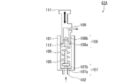
- FIG. 1st Embodiment of the fuel cell system which concerns on this invention Sectional drawing of the membrane electrode assembly used for the fuel cell system shown in FIG. Sectional drawing which shows a manual pump.
- Fuel cell system 10 Fuel supply unit 20 Fuel cell (membrane electrode assembly, MEA) 21 Anode (fuel electrode) 22 Cathode (Air electrode) 23 Electrolyte membrane 25 Anode catalyst layer 26 Anode gas diffusion layer 27 Cathode catalyst layer 28 Cathode gas diffusion layer 29 Porous body 30 Fuel distribution mechanism 31 Fuel distribution part 32 Fuel inlet 33 Gap part 34 Fuel outlet 35 Narrow tube 36 Cover plate 37a, 37b O-ring 38 Anode space 39 Cathode space 41 Fuel storage section 42 Fuel storage section main body 45 Control means 46 Attaching / detaching section 50 First fuel supply line 51 First fuel flow path (fuel flow path) 52 Automatic pump 53 Automatic shut-off valve 55 Automatic-manual shut-off valve 60 Second fuel supply line 61 Second fuel flow passage 62, 62A Manual pump 63 Manual shut-off valve 63A Switching valve (manual shut-off valve) 70 automatic-manual fuel supply line 73 first inlet 74 second inlet 75 first outlet 76 second outlet 77 first
- FIG. 1 is a diagram showing a configuration of a first embodiment of a fuel cell system according to the present invention.
- the fuel cell system 1 includes a membrane electrode assembly (MEA) 20 that generates power, a fuel supply unit 10 that supplies fuel to the membrane electrode assembly 20, a first booster circuit 93, a second booster circuit 94, an external An output terminal 95, a storage battery 91, and a control means (control circuit) 45 are provided.
- MEA membrane electrode assembly
- the fuel cell system 1 includes a membrane electrode assembly (MEA) 20 that generates power, a fuel supply unit 10 that supplies fuel to the membrane electrode assembly 20, a first booster circuit 93, a second booster circuit 94, an external An output terminal 95, a storage battery 91, and a control means (control circuit) 45 are provided.
- MEA membrane electrode assembly
- the membrane electrode assembly 20 uses fuel supplied from the fuel supply unit 10 and air (oxygen) supplied from an air intake hole (not shown) provided in the membrane electrode assembly 20. Generate electricity. The electricity generated by the membrane electrode assembly 20 is boosted by the first booster circuit 93 and the second booster circuit 94 and output from the external output terminal 95.
- the storage battery 91 is connected to a line between the first booster circuit 93 and the second booster circuit 94 via the protection circuit 92, and supplies power to the fuel cell system 1 when the membrane electrode assembly 20 is not generating power. Supply.
- Control means 45 controls the operating status in the fuel cell system 1. Specifically, the control means 45 controls the amount of fuel supplied from the fuel storage unit 41 to the fuel electrode 21 of the membrane electrode assembly 20 by the fuel supply unit 10, the operation of the first booster circuit 93 and the second booster circuit 94, and the like. To control.
- Control by the fuel supply control unit 45 in the fuel supply unit 10 is that the control unit 45 controls operations such as operation / stop of the automatic pump 52 and opening / closing of the automatic shutoff valve 53 in the fuel supply unit 10. Is done.
- FIG. 1 the transmission system of the control signal between the control means 45, the automatic pump 52, the automatic cutoff valve 53, the first booster circuit 93, and the second booster circuit 94 is indicated by a broken line.
- the fuel cell system 1 is a so-called semi-passive type direct methanol fuel cell (DMFC) system.
- DMFC direct methanol fuel cell
- the semi-passive type DMFC only the fuel supply to the fuel electrode of the membrane electrode assembly 20 is forcibly performed by a pump or the like, and the air supply to the air electrode of the membrane electrode assembly 20 is a pump. It means DMFC in a form that is performed by diffusion without using.
- active DMFCs and passive DMFCs are known as DMFCs other than the semi-passive type.
- the active type DMFC is a DMFC in which both supply of fuel to the fuel electrode and supply of air to the air electrode are forcibly performed by a pump or the like.
- the passive type DMFC is a DMFC in which fuel is supplied to the fuel electrode and air is supplied to the air electrode by diffusion without using a pump or the like.
- the semi-passive type DMFC used in the present invention can be stably supplied with fuel and can be downsized. It is a form of DMFC.
- FIG. 2 is a cross-sectional view of the membrane electrode assembly 20 used in the fuel cell system 1 shown in FIG.
- the membrane electrode assembly 20 is provided with a fuel electrode 21 and an air electrode 22 via an electrolyte membrane 23.
- the fuel electrode 21 has a two-layer structure in which a sheet-like fuel electrode catalyst layer 25 and a fuel electrode gas diffusion layer 26 are laminated.
- the air electrode 22 has a two-layer structure in which a sheet-like air electrode catalyst layer 27 and an air electrode gas diffusion layer 28 are laminated.
- the membrane electrode assembly 20 is a multilayer stack in which the fuel electrode gas diffusion layer 26 / fuel electrode catalyst layer 25 / electrolyte membrane 23 / air electrode catalyst layer 27 / air electrode gas diffusion layer 28 are stacked in this order from the fuel electrode 21 side. It has a structure.
- a cover plate 36 that protects the membrane electrode assembly 20 and maintains its shape is disposed on the outer surface of the air electrode gas diffusion layer 28 of the membrane electrode assembly 20.
- the cover plate 36 is provided with an air hole (not shown) so that air can flow between the cover plate 36 and an air intake hole (not shown) provided in the housing containing the fuel cell system 1.
- the fuel electrode catalyst layer 25 of the fuel electrode 21 and the air electrode catalyst layer 27 of the air electrode 22 are such that the catalyst is fixed to the electrolyte membrane 23 with an ion exchange resin or the like.
- Examples of the catalyst used for the fuel electrode catalyst layer 25 and the air electrode catalyst layer 27 include simple elements of platinum group elements such as Pt, Ru, Rh, Ir, Os, and Pd, alloys containing these platinum group elements, and the like. Can be mentioned.
- the electrolyte membrane 23 is an electrolyte membrane having proton (hydrogen ion) conductivity.
- Examples of the proton conductive material constituting the electrolyte membrane 23 include organic materials having a sulfonic acid group and inorganic materials such as tungstic acid and phosphotungstic acid.
- the membrane electrode assembly 20 is disposed such that the outer surface of the fuel electrode gas diffusion layer 26 faces the surface of the fuel distribution portion 31 of the fuel distribution mechanism 30.
- An O-ring 37a is interposed between the fuel distributor 31 and the electrolyte membrane 23, and an anode space 38 is formed inside.
- the fuel electrode gas diffusion layer 26 and the fuel electrode catalyst layer 25 are disposed.
- an O-ring 37b is interposed between the electrolyte membrane 23 and the cover plate 36, and a cathode space 39 is formed inside.
- An air electrode catalyst layer 27 and an air electrode gas diffusion layer 28 are disposed in the cathode space 39.
- the fuel cell system 1 is disposed so that the cover plate 36 faces an air intake hole (not shown) of the housing in which the fuel cell system 1 of the display-side main body 3 is built.
- a fuel distribution mechanism 30 is disposed on the fuel electrode 21 side of the membrane electrode assembly 20.
- the fuel distribution mechanism 30 supplies the fuel sent from the fuel supply unit 10 to the fuel electrode 21 of the membrane electrode assembly 20.
- the fuel distribution mechanism 30 includes a box-shaped fuel distribution unit 31.
- the fuel distributor 31 includes a gap 33 for containing fuel therein, a fuel inlet 32 for injecting fuel into the gap 33, and a fuel outlet 34 for discharging the fuel in the gap 33 to the outside.
- the fuel supply unit 10 includes the membrane electrode assembly 20 from the junction of the fuel accommodating portion 41, the first fuel supply line 50, the second fuel supply line 60, and the first fuel supply line 50 and the second fuel supply line 60. And a final supply line 81 for supplying fuel to the vehicle.
- the fuel storage unit 41 is a tank that can store fuel therein.
- Examples of the fuel stored in the fuel storage unit 41 include methanol fuel such as pure methanol and methanol aqueous solution, ethanol fuel such as pure ethanol and ethanol aqueous solution, propanol fuel such as propanol aqueous solution and pure propanol, aqueous glycol solution and pure glycol, and the like.
- the first fuel supply line 50 includes a first fuel flow passage 51, an automatic pump 52, and an automatic shutoff valve 53.
- the first fuel flow path 51 is a flow path for supplying fuel from the fuel storage portion 41 toward the membrane electrode assembly 20.
- the end of the first fuel flow passage 51 on the membrane electrode assembly 20 side is connected to the second fuel flow passage 61 of the second fuel supply line 60.
- the fuel in the first fuel flow passage 51 is supplied to the membrane electrode assembly 20 via the final supply line 81.
- the final supply line 81 is connected to the fuel inlet 32 of the fuel distribution mechanism 30, and the fuel in the final supply line 81 passes through the fuel distribution mechanism 30 to the fuel electrode 21 of the membrane electrode assembly 20. Supplied.
- a plastic hose, a rubber hose, a metal hose, or the like is used as the first fuel flow passage 51 and the final supply line 81.
- the automatic pump 52 is provided in the first fuel flow passage 51 and automatically operates and stops based on an instruction from the control means 45.
- a known pump capable of feeding a liquid such as an electroosmotic flow pump or a diaphragm pump, is used.
- the automatic pump 52 preferably has an output that changes stepwise or continuously.
- the automatic shutoff valve 53 is provided in the first fuel flow passage 51 and automatically opens and closes the valve based on an instruction from the control means 45.
- As the automatic shutoff valve 53 a known shutoff valve capable of adjusting the liquid flow rate is used.
- the first fuel supply line 50 has an automatic pump 52 and an automatic shut-off valve 53 controlled by the control means 45. For this reason, the first fuel supply line 50 supplies fuel only when electric power is supplied and the control means 45 operates.
- the state in which the electric power is supplied and the control means 45 operates is, for example, a power generation state in which the membrane electrode assembly 20 is generating power, or the storage battery 91 has sufficient power even if the membrane electrode assembly 20 is not generating power. It means the normal startup state that can be supplied. Note that the first fuel supply line 50 does not supply fuel because the control means 45 does not operate in an emergency when the membrane electrode assembly 20 does not generate power and the storage battery 91 cannot sufficiently supply power.
- the second fuel supply line 60 includes a second fuel flow passage 61, a manual pump 62, and a manual shutoff valve 63.
- the second fuel flow path 61 is a flow path for supplying fuel from the fuel storage portion 41 toward the membrane electrode assembly 20.
- the end of the second fuel flow passage 61 on the membrane electrode assembly 20 side is connected to the first fuel flow passage 51 of the first fuel supply line 50.
- the fuel in the second fuel flow path 61 is supplied to the membrane electrode assembly 20 via the final supply line 81.
- the second fuel flow passage 61 for example, a plastic hose, a rubber hose, a metal hose, or the like is used.
- the manual pump 62 is provided in the second fuel flow passage 61 and is manually operated.
- a manual pump 62A as shown in FIG. 3 is used as the manual pump 62.
- a manual pump 62A shown in FIG. 3 is provided in the cylinder 101, a piston 111 including a slider 112 that slides in the cylinder 101, and connected to the slider 112 via a spring 106. And a valve body 105.
- the cylinder 101 is provided with a suction port 102 and a check valve 107 that opens and closes the suction port 102.
- the check valve 107 includes a hole 107a and a ball 107b that closes the hole 107a.
- the piston 111 is provided with a discharge port 109 and a check valve 108 that opens and closes the discharge port 109.
- the check valve 108 includes a hole 108a and a ball 108b that closes the hole 108a.
- the manual pump 62A slides the piston 111 to discharge the fuel from the suction port 102 through the suction / discharge port 109.
- the manual shutoff valve 63 is provided in the second fuel flow passage 61.
- a known shutoff valve capable of adjusting the liquid flow rate is used as the manual shutoff valve 63.
- the second fuel supply line 60 has a manual pump 62 and a manual shutoff valve 63 that are not controlled by the control means 45. For this reason, the second fuel supply line 60 manually operates the manual pump 62 even in an emergency when the power for operating the control means 45 is not supplied and the first fuel supply line 50 cannot supply the fuel, and the manual shut-off is performed.
- the fuel can be supplied by opening the valve 63.
- the control means 45 operates normally. Operate. In this case, the fuel is automatically supplied from the fuel storage portion 41 to the membrane electrode assembly 20 using the first fuel supply line 50 controlled by the control means 45.
- the control means 45 does not operate normally, so fuel supply using the first fuel supply line 50 is not performed.
- the manual pump 62 of the second fuel supply line 60 is manually operated and the manual shut-off valve 63 is opened, the fuel is supplied from the fuel storage unit 41 to the membrane electrode assembly 20 using the second fuel supply line 60.
- the membrane electrode assembly 20 can generate power.
- control means 45 to which power is supplied operates normally, so that the manual fuel supply by the second fuel supply line 60 is appropriately stopped, It is preferable to switch to automatic fuel supply by one fuel supply line 50.
- the membrane electrode assembly 20 can be generated by manually operating the second fuel supply line 60 even in an emergency in which the control means 45 cannot operate normally due to insufficient power of the storage battery 91. .
- FIG. 4 is a diagram showing a configuration of a fuel supply unit 10A used in the second embodiment of the fuel cell system according to the present invention.
- the second embodiment of the fuel cell system is different from the first embodiment of the fuel cell system shown in FIG. 1 in that a fuel supply unit 10A is used instead of the fuel supply unit 10, and other configurations are the same. is there. For this reason, FIG. 4 shows only the fuel supply unit 10A.
- the fuel supply unit 10A used in the second embodiment of the fuel cell system functions as a manual cutoff valve instead of the manual cutoff valve 63, as compared with the fuel supply unit 10 used in the first embodiment of the fuel cell system.
- the configuration is the same except that the switching valve 63A is used and a feedback line 83 that connects the outlet of the switching valve 63A and the fuel storage portion 41 is further provided.
- the switching valve 63A is an embodiment of a manual cutoff valve.
- the switching valve 63 ⁇ / b> A is provided at the end of the second fuel flow path 61 on the membrane electrode assembly 20 side and the end of the first fuel flow path 51 of the first fuel supply line 50 on the membrane electrode assembly 20 side. Connected to. That is, the switching valve 63 ⁇ / b> A is provided at a junction of the first fuel supply line 50 and the second fuel supply line 60 on the membrane electrode assembly 20 side.
- the switching valve 63A includes a housing (not shown) and a flow path switching member that is rotatably provided in the housing and has two independent flow paths (a first flow path 77 and a second flow path 78).
- the switching valve 63A outputs two systems with respect to two systems.
- the first flow path 77 means a flow path connected to the first fuel supply line 50
- the second flow path 78 means a flow path connected to the second fuel supply line 60.
- the housing of the switching valve 63A is provided with a first inlet 73, a second inlet 74, a first outlet 75, and a second outlet 76.
- the first fuel flow path 51 of the first fuel supply line 50 is connected to the first inlet 73
- the second fuel flow path 61 of the second fuel supply line 60 is connected to the second inlet 74.
- the flow path switching member provided in the housing is capable of selecting two flow path states by rotating in the housing. Specifically, the flow path switching member rotates in the housing so that the first flow path 77 communicates between the first inlet 73 and the first outlet 75 and the second flow path 78 is the second inlet 74.
- a flow path state (first flow path state) communicating between the second outlets 76, or the first flow path 77 communicates between the first inlet 73 and the second outlet 76 and the second flow path 78 is Any one of the flow channel states (second flow channel state) communicating between the two inlets 74 and the first outlet 75 can be selected.
- the switching valve 63A communicates one of the first fuel supply line 50 and the second fuel supply line 60 to the first outlet 75 and the other system to the second outlet 76. It is configured as follows.
- a final supply line 81 is connected to the first outlet 75 of the switching valve 63A.
- the final supply line 81 supplies the fuel supplied from the first fuel supply line 50 or the second fuel supply line 60 to the membrane electrode assembly 20.
- the second outlet 76 of the switching valve 63A is provided with a feedback line 83 that allows the switching valve 63A and the fuel storage unit 41 to communicate with each other.
- the return line 83 returns the fuel supplied from the first fuel supply line 50 or the second fuel supply line 60 to the fuel storage unit 41. The fuel returned to the fuel storage unit 41 is reused.
- FIG. 5 is a diagram showing the operation of the fuel supply unit 10A used in the second embodiment of the fuel cell system.
- the control means 45 operates normally. Operate.
- the flow path state of the switching valve 63A as the manual shutoff valve is such that the first flow path 77 connects between the first inlet 73 and the first outlet 75 to supply the first fuel.
- the line 50 communicates with the first outlet 75, and the second flow path 78 connects the second inlet 74 and the second outlet 76 to communicate the second fuel supply line 60 and the second outlet 76.
- State first flow path state).
- the fuel is automatically supplied from the fuel storage unit 41 to the membrane electrode assembly 20 using the first fuel supply line 50 and the final supply line 81 controlled by the control means 45.
- the control means 45 does not operate normally, so fuel supply using the first fuel supply line 50 is not performed.
- the flow path state of the switching valve 63A is such that the first flow path 77 connects between the first inlet 73 and the second outlet 76 so that the first fuel supply line 50 and the second outlet 76 are connected.
- the second flow path 78 connects the second inlet 74 and the first outlet 75 so as to communicate the second fuel supply line 60 and the first outlet 75 (second flow path). State).
- the fuel is transferred from the fuel container 41 to the membrane electrode assembly 20 using the second fuel supply line 60 and the final supply line 81. Power is supplied to the membrane electrode assembly 20.
- the control means 45 to which power is supplied operates normally. Therefore, the flow path state of the switching valve 63A is appropriately changed to the second state shown in FIG. It is preferable to switch from the flow path state to the first flow path state shown in FIG. 4 and switch to automatic fuel supply by the first fuel supply line 50.
- the liquid is fed to the membrane electrode assembly 20 by using the switching valve 63A.
- the first fuel supply line 50 and the second fuel supply line 60 can be easily selected or switched.
- the feedback line 83 connected to the switching valve 63 ⁇ / b> A the excessively supplied fuel can be returned to the fuel storage unit 41.
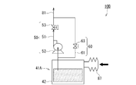
- FIG. 6 is a diagram showing a configuration of a fuel supply unit 10B used in the third embodiment of the fuel cell system according to the present invention.
- the third embodiment of the fuel cell system is different from the first embodiment of the fuel cell system shown in FIG. 1 in that a fuel supply unit 10B is used instead of the fuel supply unit 10, and other configurations are the same. is there. For this reason, FIG. 6 shows only the fuel supply unit 10B.
- the fuel supply unit 10B used in the third embodiment of the fuel cell system uses a fuel storage unit 41A instead of the fuel storage unit 41.
- the configuration is the same except that the manual pump 62 is not provided.
- the fuel storage section 41A includes a fuel storage section main body 42 that stores fuel, and a pressurizing means 87 that pressurizes the inside of the fuel storage section main body 42 through a hole (not shown) that communicates the inside and outside of the fuel storage section main body 42. Is.
- a manual pump made of a flexible material can be used as the pressurizing means 87.
- the manual pump made of a flexible material include a bellows pump made of polyolefin such as polypropylene.
- the control means 45 operates normally. Operate. In this case, the fuel is automatically supplied from the fuel storage portion 41 ⁇ / b> A to the membrane electrode assembly 20 using the first fuel supply line 50 controlled by the control means 45.
- the control means 45 does not operate normally, so fuel supply using the first fuel supply line 50 is not performed.
- the inside of the fuel storage unit main body 42 of the fuel storage unit 41A is manually pressurized using the pressurizing means 87 and the manual shutoff valve 63 of the second fuel supply line 60 is opened, the fuel is supplied to the second fuel supply line 60. Is supplied from the fuel storage portion 41A to the membrane electrode assembly 20, and the membrane electrode assembly 20 can generate power.
- control means 45 to which power is supplied operates normally, so that the manual fuel supply by the second fuel supply line 60 is appropriately stopped, It is preferable to switch to automatic fuel supply by one fuel supply line 50.
- the use of the fuel storage portion 41A including the pressurizing means 87 allows the first Since it is not necessary to provide the manual pump 62 in the two fuel supply lines 60, the second fuel supply line 60 can be simplified.
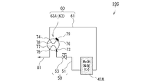
- FIG. 7 is a diagram showing a configuration of a fuel supply unit 10C used in the fourth embodiment of the fuel cell system according to the present invention.
- the fourth embodiment of the fuel cell system is different from the first embodiment of the fuel cell system shown in FIG. 1 in that a fuel supply unit 10C is used instead of the fuel supply unit 10, and other configurations are the same. is there. For this reason, FIG. 7 shows only the fuel supply unit 10C.
- the fuel supply unit 10C used in the fourth embodiment of the fuel cell system uses a fuel storage unit 41A instead of the fuel storage unit 41, as compared with the fuel supply unit 10A used in the second embodiment of the fuel cell system.
- the configuration is the same except that the automatic pump 52 and the manual pump 62 are not provided, and the feedback line 83 is not provided.
- the fuel container 41A used in the present embodiment is the same as the fuel container 41A used in the fuel supply unit 10B constituting the third embodiment of the fuel cell system.
- the second outlet 76 of the switching valve 63A is provided with a closing portion 79 that closes the second outlet 76.
- Examples of the closing portion 79 include a blind cap that closes the second outlet 76.
- FIG. 8 is a diagram showing the operation of the fuel supply unit 10C used in the fourth embodiment of the fuel cell system.
- the control means 45 operates normally. Operate.
- the flow path state of the switching valve 63A as the manual shutoff valve is such that the first flow path 77 connects between the first inlet 73 and the first outlet 75 to supply the first fuel.
- the line 50 communicates with the first outlet 75, and the second flow path 78 connects the second inlet 74 and the second outlet 76 to communicate the second fuel supply line 60 and the second outlet 76.
- State first flow path state).
- the fuel is supplied from the fuel storage portion 41A to the membrane electrode assembly 20 using the first fuel supply line 50 and the final supply line 81. Automatically supplied.
- the control means 45 controls only the open / close state of the automatic shutoff valve 53.
- the fuel Since the inside of the fuel storage portion 41A is pressurized by the pressurizing means 87, the fuel is switched from the fuel storage portion 41A to the switching valve using both the first fuel supply line 50 and the second fuel supply line 60. Automatically supplied up to 63A. However, since the fuel supplied from the second fuel supply line 60 to the switching valve 63A is guided to the second outlet 76 side where the blocking portion 79 is provided via the second flow path 78, the switching valve 63A It is not discharged and fuel is not wasted.
- the control means 45 does not operate normally, so that fuel supply using the first fuel supply line 50 is not performed.
- the flow path state of the switching valve 63A is such that the first flow path 77 connects between the first inlet 73 and the second outlet 76 so that the first fuel supply line 50 and the second outlet 76 are connected.
- the second flow path 78 connects the second inlet 74 and the first outlet 75 so as to communicate the second fuel supply line 60 and the first outlet 75 (second flow path). State).
- the fuel is supplied from the fuel storage portion 41A to the membrane electrode assembly 20 using the second fuel supply line 60 and the final supply line 81.
- the membrane electrode assembly 20 can generate power.
- the control means 45 supplied with electric power normally operates after the membrane electrode assembly 20 starts generating power
- the flow path state of the switching valve 63A is appropriately changed to the second state shown in FIG. It is preferable to switch from the flow path state to the first flow path state shown in FIG. 7 and switch to automatic fuel supply by the first fuel supply line 50.
- the liquid is fed to the membrane electrode assembly 20 by using the switching valve 63 ⁇ / b> A.
- the first fuel supply line 50 and the second fuel supply line 60 can be easily selected or switched.
- the automatic pump 52 is not provided in the 1st fuel supply line 50, an apparatus structure can be simplified.
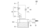
- FIG. 9 is a diagram showing a configuration of a fuel supply unit 10D used in the fifth embodiment of the fuel cell system according to the present invention.
- the fifth embodiment of the fuel cell system is different from the first embodiment of the fuel cell system shown in FIG. 1 in that a fuel supply unit 10D is used instead of the fuel supply unit 10, and other configurations are the same. is there. For this reason, FIG. 9 shows only the fuel supply unit 10D.
- the fuel supply unit 10D used in the fifth embodiment of the fuel cell system uses a fuel storage portion 41B instead of the fuel storage portion 41A, as compared with the fuel supply unit 10B used in the third embodiment of the fuel cell system.
- the configuration is the same except for the points described above.
- the fuel accommodating portion 41B includes a fuel accommodating portion main body 42 that is provided with a hole portion that accommodates fuel and communicates inside and outside, an attachment / detachment portion 46 that is fixed to the hole portion and that can attach / detach the pressurizing means 87, and an attachment / detachment portion. Pressure means 87 detachably fixed to 46.
- attachment / detachment unit 46 examples include a pipe.
- the material of the detachable part 46 is not particularly limited.
- the operation of the fifth embodiment of the fuel cell system provided with the fuel supply unit 10D is the same as that of the third embodiment of the fuel cell system provided with the fuel supply unit 10B, and thus the description thereof is omitted.
- the fuel storage unit 41B including the pressurizing unit 87 is used to Since it is not necessary to provide the manual pump 62 in the two fuel supply lines 60, the second fuel supply line 60 can be simplified. Further, since the pressurizing means 87 of the fuel storage portion 41B is detachable, the space for the bulky pressurizing means 87 such as a bellows type pump can be reduced.
- FIG. 10 is a diagram showing a configuration of a fuel supply unit 10D used in the sixth embodiment of the fuel cell system according to the present invention.
- the sixth embodiment of the fuel cell system is different from the first embodiment of the fuel cell system shown in FIG. 1 in that a fuel supply unit 10E is used instead of the fuel supply unit 10, and other configurations are the same. is there. For this reason, only the fuel supply unit 10E is shown in FIG.
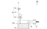
- the fuel supply unit 10E used in the sixth embodiment of the fuel cell system does not include the second fuel supply line 60 as compared with the fuel supply unit 10D used in the fifth embodiment of the fuel cell system, and A similar configuration is provided except that an auto-manual fuel supply line 70 is provided instead of the one fuel supply line 50.
- the auto-manual fuel supply line 70 includes a fuel flow passage 51, an automatic pump 52, and an auto-manual shut-off valve 55. That is, the automatic-manual fuel supply line 70 is an automatic-manual cutoff valve in the first fuel supply line 50 of the fuel supply unit 10D used in the fifth embodiment of the fuel cell system shown in FIG. This is a replacement for 55.
- the automatic-manual shutoff valve 55 is provided in the fuel flow passage 51, and opens or closes the valve automatically or manually based on an instruction from the control means 45.
- As the automatic-manual shut-off valve 55 a known shut-off valve capable of adjusting the liquid flow rate is used.
- the auto-manual fuel supply line 70 has an automatic pump 52 controlled by the control means 45 and an auto-manual shut-off valve 55 controlled automatically or manually by the control means 45.
- the control means 45 operates normally. Operate. In this case, the automatic pump 52 controlled by the control means 45 automatically operates / stops, and the auto-manual shut-off valve 55 controlled by the control means 45 automatically opens / closes the valves. Thereby, the fuel is automatically supplied from the fuel storage part 41B to the membrane electrode assembly 20.
- the control means 45 does not operate normally and the automatic pump 52 does not operate, so fuel is automatically supplied. There is nothing.
- the fuel is supplied from the fuel container 41B to the membrane electrode assembly by pressurizing the inside of the fuel container body 42 of the fuel container 41B using the pressurizing means 87 and manually opening the automatic-manual shut-off valve 55. 20, power generation of the membrane electrode assembly 20 becomes possible.
- control means 45 to which power is supplied operates normally after the membrane electrode assembly 20 starts to generate power, the automatic fuel supply using the automatic pump 52 and the automatic-manual shut-off valve 55 is appropriately performed. It is preferable to switch to supply.
- the fuel storage unit 41B including the pressurizing means 87 and the automatic-manual cutoff valve One automatic-manual fuel supply line 70 using 55 enables automatic or manual fuel supply.
Landscapes
- Life Sciences & Earth Sciences (AREA)
- Engineering & Computer Science (AREA)
- Manufacturing & Machinery (AREA)
- Sustainable Development (AREA)
- Sustainable Energy (AREA)
- Chemical & Material Sciences (AREA)
- Chemical Kinetics & Catalysis (AREA)
- Electrochemistry (AREA)
- General Chemical & Material Sciences (AREA)
- Fuel Cell (AREA)
Abstract
本発明に係る燃料電池システム1は、膜電極接合体20と、燃料収容部41と、燃料収容部41から膜電極接合体20への燃料供給を制御する制御手段45と、膜電極接合体20の起動時に制御手段45に電力を供給する蓄電池91と、燃料収容部41から膜電極接合体20に向けて燃料を供給する第1の燃料流通路51、制御手段45の指示に基づき稼働する自動ポンプ52および制御手段45の指示に基づき稼働する自動遮断バルブ53を有する第1燃料供給ライン50と、燃料収容部41から膜電極接合体20に向けて燃料を供給する第2の燃料流通路61、手動ポンプ62および手動遮断バルブ63を有する第2燃料供給ライン60と、を備える。
Description
本発明は燃料電池システムに関し、詳しくは、膜電極接合体の発電出力を安定させる制御手段を駆動する蓄電池が消耗した場合でも、発電が可能な燃料電池システムに関する。
近年、電子技術の進歩により、電子機器の小型化、高性能化、ポータブル化が進んでいる。また、携帯用電子機器においては、使用される電池の高エネルギー密度化への要求が高まっている。このため、軽量で小型でありながら高容量の二次電池が要求されている。
このような状況のもと、小型の燃料電池システムが注目を集めている。特に、メタノールを燃料として用いた直接メタノール型燃料電池システム(DMFC:direct methanol fuel cell)は、エネルギー密度の高いメタノールを酸化分解して電流を直接取り出すことができるため、メタノール改質型燃料電池システムのように有機燃料から水素を作り出す改質器が不要である。このため、DMFCは、出力密度を高くするとともに小型化することが可能であり、携帯機器用の電源として有望視されている。
DMFCは、メタノールが供給される燃料極と、プロトン伝導性の電解質膜と、酸素を取り込む空気極(酸化剤極)とがこの順番に積層された膜電極接合体を備える。
DMFCでは、燃料極において式(1)の反応が生じ、メタノールが酸化分解され、二酸化炭素、プロトンおよび電子が生成される。一方、空気極(酸化剤極)においては式(2)の反応が生じ、酸素と、燃料極から電解質膜を経て供給されるプロトンと、燃料極から外部回路を通じて供給される電子とによって水が生成される。DMFCは、この外部回路を通る電子によって電力を外部に供給する。
[化1]
燃料極:CH3OH+H2O→CO2+6H++6e- (1)
[化2]
空気極:6H++(3/2)O2+6e-→3H2O (2)
DMFCには、燃料極への燃料の供給および空気極への空気(酸素)の供給の仕方によりアクティブ型、セミパッシブ型およびパッシブ型の三形態のDMFCがある。
[化1]
燃料極:CH3OH+H2O→CO2+6H++6e- (1)
[化2]
空気極:6H++(3/2)O2+6e-→3H2O (2)
DMFCには、燃料極への燃料の供給および空気極への空気(酸素)の供給の仕方によりアクティブ型、セミパッシブ型およびパッシブ型の三形態のDMFCがある。
アクティブ型のDMFCとは、燃料極への燃料の供給や空気極への空気の供給をポンプ、ファン等を用いて強制的に行う形態のDMFCである。セミパッシブ型のDMFCとは、燃料極への燃料の供給をポンプ等を用いて行うが燃料を燃料タンクには循環させず、かつ空気極への空気の供給を拡散で行う形態のDMFCである。パッシブ型のDMFCとは、燃料極への燃料の供給および空気極への空気の供給を共に拡散で行う形態のDMFCである。
これらのDMFCのうち、セミパッシブ型のDMFCは、ポンプ等の補器が少ないため小型化が可能であり、かつ燃料極への燃料の供給が安定しているため好ましい。
ところで、DMFCには、通常、膜電極接合体での発電出力を安定させるための制御手段が設けられる。この制御手段は、たとえば、膜電極接合体の発電出力を検知し、この検知した出力値に基づいて膜電極接合体の燃料極に供給する燃料量の制御等を行うものであり、電力で動作する。このため、DMFCには、通常、膜電極接合体が発電していない場合に制御手段を動作させることができるようにさらに内蔵蓄電池が設けられている。
しかし、内蔵蓄電池は、自己放電したり、DMFC内の保護回路、昇圧回路等で電力が内部消費されたりすることにより消耗する。このため、DMFCを使用しない期間が長いと、内蔵蓄電池が消耗して保護回路や制御手段に電力を供給することができなくなりDMFCを起動できなくなる場合がある。
これに対し、従来、内蔵蓄電池が消耗した場合に、DMFCに外部電源を接続して制御手段を動作させることが行われてきた。しかし、DMFCを屋外で使用する場合等のように外部電源がない場合には、DMFCの起動ができないという問題があった。
なお、DMFCの空気極への空気供給系に支障を来たしたときに空気極に空気を供給する燃料電池システムに関する従来技術としては、特開2004-311076号公報(特許文献1)が知られている。
特許文献1に開示された燃料電池システムは、アクティブ型のDMFCを用いたシステムであり、空気極用のエアコンプレッサが故障したときに燃料極用のエアコンプレッサを用いて空気極に空気を供給するものである。
特開2004-311076号公報
特許文献1に開示された燃料電池システムは、空気極用のエアコンプレッサが故障したときに空気極に空気を供給する手段を備えたシステムであり、内蔵蓄電池が消耗してDMFCの起動ができない場合にDMFCを起動可能にするシステムではない。
本発明は、上記事情に鑑みてなされたものであり、内蔵蓄電池が消耗した場合でも起動が可能な直接メタノール型燃料電池システムを提供することを目的とする。
本発明者らは、制御手段の指示に基づき膜電極接合体へ燃料を供給する通常の燃料供給系統に加え、内蔵蓄電池が消耗した場合でも膜電極接合体へ燃料を供給する燃料供給系統をさらに設ければ、内蔵蓄電池が消耗した場合でも起動が可能な直接メタノール型燃料電池システムが得られることを見出し、本発明を完成するに至った。
本発明に係る燃料電池システムは、上記問題点を解決するものであり、燃料極と、空気極と、前記燃料極および空気極に挟持された電解質膜とを有する膜電極接合体と、燃料を収容する燃料収容部と、前記燃料収容部から膜電極接合体への燃料供給を制御する制御手段と、前記膜電極接合体の起動時に前記制御手段に電力を供給する蓄電池と、前記燃料収容部から膜電極接合体に向けて燃料を供給する第1の燃料流通路と、前記第1の燃料流通路に設けられ、前記制御手段の指示に基づき稼働する自動ポンプと、前記第1の燃料流通路に設けられ、前記制御手段の指示に基づき稼働する自動遮断バルブとを有する第1燃料供給ラインと、前記燃料収容部から膜電極接合体に向けて燃料を供給する第2の燃料流通路と、前記第2の燃料流通路に設けられる手動ポンプと、前記第2の燃料流通路に設けられる手動遮断バルブとを有する第2燃料供給ラインと、を備えたことを特徴とする。
また、本発明に係る燃料電池システムは、上記問題点を解決するものであり、燃料極と、空気極と、前記燃料極および空気極に挟持された電解質膜とを有する膜電極接合体と、燃料を収容する燃料収容部本体と、この燃料収容部本体の内部を加圧する加圧手段とを備えた燃料収容部と、前記燃料収容部から膜電極接合体への燃料供給を制御する制御手段と、前記膜電極接合体の起動時に前記制御手段に電力を供給する蓄電池と、前記燃料収容部から膜電極接合体に向けて燃料を供給する第1の燃料流通路と、前記第1の燃料流通路に設けられ、前記制御手段の指示に基づき稼働する自動ポンプと、前記第1の燃料流通路に設けられ、前記制御手段の指示に基づき稼働する自動遮断バルブとを有する第1燃料供給ラインと、前記燃料収容部から膜電極接合体に向けて燃料を供給する第2の燃料流通路と、前記第2の燃料流通路に設けられる手動遮断バルブとを有する第2燃料供給ラインと、を備えたことを特徴とする。
さらに、本発明に係る燃料電池システムは、上記問題点を解決するものであり、燃料極と、空気極と、前記燃料極および空気極に挟持された電解質膜とを有する膜電極接合体と、燃料を収容する燃料収容部本体と、この燃料収容部本体の内部を加圧する加圧手段とを備えた燃料収容部と、前記燃料収容部から膜電極接合体への燃料供給を制御する制御手段と、前記膜電極接合体の起動時に前記制御手段に電力を供給する蓄電池と、前記燃料収容部から膜電極接合体に向けて燃料を供給する燃料流通路と、前記燃料流通路に設けられ、前記制御手段の指示に基づき稼働する自動ポンプと、前記燃料流通路に設けられ、前記制御手段の指示に基づきまたは手動で稼働する自動-手動遮断バルブとを有する自動-手動燃料供給ラインと、を備えたことを特徴とする。
本発明に係る燃料電池システムによれば、燃料電池システムの内蔵蓄電池が消耗した場合でも起動が可能になる。
1 燃料電池システム
10 燃料供給ユニット
20 燃料電池セル(膜電極接合体、MEA)
21 アノード(燃料極)
22 カソード(空気極)
23 電解質膜
25 アノード触媒層
26 アノードガス拡散層
27 カソード触媒層
28 カソードガス拡散層
29 多孔体
30 燃料分配機構
31 燃料分配部
32 燃料注入口
33 空隙部
34 燃料排出口
35 細管
36 カバープレート
37a、37b Oリング
38 アノード空間
39 カソード空間
41 燃料収容部
42 燃料収容部本体
45 制御手段
46 着脱部
50 第1燃料供給ライン
51 第1の燃料流通路(燃料流通路)
52 自動ポンプ
53 自動遮断バルブ
55 自動-手動遮断バルブ
60 第2燃料供給ライン
61 第2の燃料流通路
62、62A 手動ポンプ
63 手動遮断バルブ
63A 切替弁(手動遮断バルブ)
70 自動-手動燃料供給ライン
73 第1入口
74 第2入口
75 第1出口
76 第2出口
77 第1流路
78 第2流路
79 閉塞部
81 最終供給ライン
83 帰還ライン
87 加圧手段
90 燃料供給ユニット
91 蓄電池
92 保護回路
93 第1昇圧回路
94 第2昇圧回路
95 外部出力端子
101 シリンダ
102 吸込口
105 弁体
106 バネ
107、108 逆止弁
107a、108a 孔部
107b、108b ボール
109 排出口
111 ピストン
112 摺動子
10 燃料供給ユニット
20 燃料電池セル(膜電極接合体、MEA)
21 アノード(燃料極)
22 カソード(空気極)
23 電解質膜
25 アノード触媒層
26 アノードガス拡散層
27 カソード触媒層
28 カソードガス拡散層
29 多孔体
30 燃料分配機構
31 燃料分配部
32 燃料注入口
33 空隙部
34 燃料排出口
35 細管
36 カバープレート
37a、37b Oリング
38 アノード空間
39 カソード空間
41 燃料収容部
42 燃料収容部本体
45 制御手段
46 着脱部
50 第1燃料供給ライン
51 第1の燃料流通路(燃料流通路)
52 自動ポンプ
53 自動遮断バルブ
55 自動-手動遮断バルブ
60 第2燃料供給ライン
61 第2の燃料流通路
62、62A 手動ポンプ
63 手動遮断バルブ
63A 切替弁(手動遮断バルブ)
70 自動-手動燃料供給ライン
73 第1入口
74 第2入口
75 第1出口
76 第2出口
77 第1流路
78 第2流路
79 閉塞部
81 最終供給ライン
83 帰還ライン
87 加圧手段
90 燃料供給ユニット
91 蓄電池
92 保護回路
93 第1昇圧回路
94 第2昇圧回路
95 外部出力端子
101 シリンダ
102 吸込口
105 弁体
106 バネ
107、108 逆止弁
107a、108a 孔部
107b、108b ボール
109 排出口
111 ピストン
112 摺動子
[第1実施形態]
本発明に係る燃料電池システムの第1実施形態について、図面を参照して説明する。図1は、本発明に係る燃料電池システムの第1実施形態の構成を示す図である。
本発明に係る燃料電池システムの第1実施形態について、図面を参照して説明する。図1は、本発明に係る燃料電池システムの第1実施形態の構成を示す図である。
燃料電池システム1は、発電を行う膜電極接合体(MEA)20と、膜電極接合体20に燃料を供給する燃料供給ユニット10と、第1昇圧回路93と、第2昇圧回路94と、外部出力端子95と、蓄電池91と、制御手段(制御回路)45とを備える。
燃料電池システム1では、膜電極接合体20が、燃料供給ユニット10から供給された燃料と、膜電極接合体20に設けられた図示しない空気取り入れ孔から供給された空気(酸素)とを用いて発電する。膜電極接合体20で発電された電気は、第1昇圧回路93および第2昇圧回路94で昇圧され、外部出力端子95から出力される。
蓄電池91は、保護回路92を介して第1昇圧回路93-第2昇圧回路94間のラインに接続され、膜電極接合体20が発電していない起動時等に燃料電池システム1内に電力を供給する。
制御手段45は、燃料電池システム1内の稼働状況を制御する。具体的には、制御手段45は、燃料供給ユニット10による燃料収容部41から膜電極接合体20の燃料極21への燃料供給量や、第1昇圧回路93および第2昇圧回路94の動作等を制御する。
燃料供給ユニット10での燃料供給の制御手段45による制御は、制御手段45が、燃料供給ユニット10中の自動ポンプ52の稼働-停止や自動遮断バルブ53の開放-閉塞等の動作を制御することにより行われる。図1中、制御手段45と、自動ポンプ52、自動遮断バルブ53、第1昇圧回路93および第2昇圧回路94との間の制御信号の伝送系統を破線で示す。
燃料電池システム1は、いわゆるセミパッシブ型の直接メタノール型燃料電池(DMFC)のシステムである。ここで、セミパッシブ型のDMFCとは、膜電極接合体20の燃料極への燃料の供給のみがポンプ等で強制的に行われ、膜電極接合体20の空気極への空気の供給がポンプ等を用いず拡散で行われる形態のDMFCを意味する。
なお、セミパッシブ型以外のDMFCとしては、アクティブ型のDMFCや、パッシブ型のDMFCが知られている。アクティブ型のDMFCとは、燃料極への燃料の供給および空気極への空気の供給が共にポンプ等で強制的に行われる形態のDMFCである。また、パッシブ型のDMFCとは、燃料極への燃料の供給および空気極への空気の供給が共にポンプ等を用いず拡散で行われる形態のDMFCである。
アクティブ型、セミパッシブ型およびパッシブ型のDMFCのうち、本発明に用いられるセミパッシブ型のDMFCは、燃料の安定供給が可能であるとともに、小型化が可能であるため、現在、開発が望まれている形態のDMFCである。
(膜電極接合体)
図2は、図1に示す燃料電池システム1に用いられる膜電極接合体20の断面図である。
図2は、図1に示す燃料電池システム1に用いられる膜電極接合体20の断面図である。
膜電極接合体20は、燃料極21と空気極22とが電解質膜23を介して設けられている。燃料極21は、シート状の燃料極触媒層25と燃料極ガス拡散層26とが積層された2層構造を有する。空気極22は、シート状の空気極触媒層27と空気極ガス拡散層28とが積層された2層構造を有する。
膜電極接合体20は、燃料極21側から、燃料極ガス拡散層26/燃料極触媒層25/電解質膜23/空気極触媒層27/空気極ガス拡散層28の順番に積層された多層積層構造になっている。膜電極接合体20の空気極ガス拡散層28の外側表面には、膜電極接合体20を保護し形状を維持するカバープレート36が配置される。カバープレート36には、図示しない空気孔が設けられ、燃料電池システム1を内蔵する筐体に設けられた図示しない空気取入孔との間で空気の流通が可能になっている。
燃料極21の燃料極触媒層25および空気極22の空気極触媒層27は、触媒が電解質膜23にイオン交換樹脂等で固着されたものになっている。燃料極触媒層25および空気極触媒層27に用いられる触媒としては、たとえば、Pt、Ru、Rh、Ir、Os、Pd等の白金族元素の単体や、これら白金族元素を含有する合金等が挙げられる。
電解質膜23は、プロトン(水素イオン)伝導性を有する電解質膜である。電解質膜23構成するプロトン伝導性材料としては、たとえば、スルホン酸基を有する有機系材料や、タングステン酸、リンタングステン酸等の無機系材料が挙げられる。
膜電極接合体20は、燃料極ガス拡散層26の外側表面が燃料分配機構30の燃料分配部31の表面に相対するように配置される。
燃料分配部31と電解質膜23との間にはOリング37aが介装され、内部にアノード空間38が形成される。アノード空間38内には、燃料極ガス拡散層26および燃料極触媒層25が配置される。
また、電解質膜23とカバープレート36との間にはOリング37bが介装され、内部にカソード空間39が形成される。カソード空間39内には、空気極触媒層27および空気極ガス拡散層28が配置される。
燃料電池システム1は、カバープレート36が、表示側本体3の燃料電池システム1を内蔵する筐体の図示しない空気取入孔に相対するように配置される。
膜電極接合体20の燃料極21側には、燃料分配機構30が配置される。燃料分配機構30は、燃料供給ユニット10から送液された燃料を膜電極接合体20の燃料極21に供給する。燃料分配機構30は、ボックス状の燃料分配部31からなる。燃料分配部31は、燃料を内部に収容する空隙部33と、燃料を空隙部33内に注入するための燃料注入口32と、空隙部33内の燃料を外部に排出する燃料排出口34とを有する。
(燃料供給ユニット)
燃料供給ユニット10は、燃料収容部41と、第1燃料供給ライン50と、第2燃料供給ライン60と、第1燃料供給ライン50および第2燃料供給ライン60の合流点から膜電極接合体20へ燃料を供給する最終供給ライン81とを備える。
燃料供給ユニット10は、燃料収容部41と、第1燃料供給ライン50と、第2燃料供給ライン60と、第1燃料供給ライン50および第2燃料供給ライン60の合流点から膜電極接合体20へ燃料を供給する最終供給ライン81とを備える。
<燃料収容部>
燃料収容部41は、内部に燃料を収容可能なタンクである。燃料収容部41に収容される燃料としては、たとえば、純メタノールやメタノール水溶液等のメタノール燃料、純エタノールやエタノール水溶液等のエタノール燃料、プロパノール水溶液や純プロパノール等のプロパノール燃料、グリコール水溶液や純グリコール等のグリコール燃料、ジメチルエーテル、プジメチルエーテル、蟻酸、もしくはその他の液体燃料が挙げられる。いずれにしても、燃料電池に応じた液体燃料が収容される。
燃料収容部41は、内部に燃料を収容可能なタンクである。燃料収容部41に収容される燃料としては、たとえば、純メタノールやメタノール水溶液等のメタノール燃料、純エタノールやエタノール水溶液等のエタノール燃料、プロパノール水溶液や純プロパノール等のプロパノール燃料、グリコール水溶液や純グリコール等のグリコール燃料、ジメチルエーテル、プジメチルエーテル、蟻酸、もしくはその他の液体燃料が挙げられる。いずれにしても、燃料電池に応じた液体燃料が収容される。
<第1燃料供給ライン>
第1燃料供給ライン50は、第1の燃料流通路51と、自動ポンプ52と、自動遮断バルブ53とを有する。
第1燃料供給ライン50は、第1の燃料流通路51と、自動ポンプ52と、自動遮断バルブ53とを有する。
{第1の燃料流通路}
第1の燃料流通路51は、燃料収容部41から膜電極接合体20に向けて燃料を供給する流路である。第1の燃料流通路51の膜電極接合体20側の端部は第2燃料供給ライン60の第2の燃料流通路61と接続される。第1の燃料流通路51中の燃料は、最終供給ライン81を介して膜電極接合体20へ供給される。
第1の燃料流通路51は、燃料収容部41から膜電極接合体20に向けて燃料を供給する流路である。第1の燃料流通路51の膜電極接合体20側の端部は第2燃料供給ライン60の第2の燃料流通路61と接続される。第1の燃料流通路51中の燃料は、最終供給ライン81を介して膜電極接合体20へ供給される。
図2に示すように、最終供給ライン81は燃料分配機構30の燃料注入口32に接続され、最終供給ライン81中の燃料は燃料分配機構30を介して膜電極接合体20の燃料極21へ供給される。第1の燃料流通路51および最終供給ライン81としては、たとえば、プラスチックホース、ゴムホースや金属ホース等が用いられる。
{自動ポンプ}
自動ポンプ52は、第1の燃料流通路51に設けられ、制御手段45の指示に基づき自動的に稼働-停止を行う。自動ポンプ52としては、電気浸透流ポンプやダイアフラムポンプ等の、液体を送液可能な公知のポンプが用いられる。自動ポンプ52は、出力が段階的または連続的に変化するものとすることが好ましい。
自動ポンプ52は、第1の燃料流通路51に設けられ、制御手段45の指示に基づき自動的に稼働-停止を行う。自動ポンプ52としては、電気浸透流ポンプやダイアフラムポンプ等の、液体を送液可能な公知のポンプが用いられる。自動ポンプ52は、出力が段階的または連続的に変化するものとすることが好ましい。
{自動遮断バルブ}
自動遮断バルブ53は、第1の燃料流通路51に設けられ、制御手段45の指示に基づき自動的にバルブの開放-閉塞を行う。自動遮断バルブ53としては、液体の流量を調整可能な公知の遮断バルブが用いられる。
自動遮断バルブ53は、第1の燃料流通路51に設けられ、制御手段45の指示に基づき自動的にバルブの開放-閉塞を行う。自動遮断バルブ53としては、液体の流量を調整可能な公知の遮断バルブが用いられる。
第1燃料供給ライン50は、制御手段45で制御される自動ポンプ52や自動遮断バルブ53を有する。このため、第1燃料供給ライン50は、電力が供給されて制御手段45が動作する状態にのみ燃料を供給する。
電力が供給されて制御手段45が動作する状態とは、たとえば、膜電極接合体20が発電している発電状態や、膜電極接合体20が発電していなくても蓄電池91が電力を十分に供給できる通常の起動状態を意味する。なお、膜電極接合体20が発電せずかつ蓄電池91が電力を十分に供給できない非常時には、制御手段45が動作しないため、第1燃料供給ライン50は燃料を供給しない。
<第2燃料供給ライン>
第2燃料供給ライン60は、第2の燃料流通路61と、手動ポンプ62と、手動遮断バルブ63とを有する。
第2燃料供給ライン60は、第2の燃料流通路61と、手動ポンプ62と、手動遮断バルブ63とを有する。
{第2の燃料流通路}
第2の燃料流通路61は、燃料収容部41から膜電極接合体20に向けて燃料を供給する流路である。第2の燃料流通路61の膜電極接合体20側の端部は第1燃料供給ライン50の第1の燃料流通路51と接続される。第2の燃料流通路61中の燃料は、最終供給ライン81を介して膜電極接合体20へ供給される。
第2の燃料流通路61は、燃料収容部41から膜電極接合体20に向けて燃料を供給する流路である。第2の燃料流通路61の膜電極接合体20側の端部は第1燃料供給ライン50の第1の燃料流通路51と接続される。第2の燃料流通路61中の燃料は、最終供給ライン81を介して膜電極接合体20へ供給される。
第2の燃料流通路61としては、たとえば、プラスチックホース、ゴムホースや金属ホース等が用いられる。
{手動ポンプ}
手動ポンプ62は、第2の燃料流通路61に設けられ、手動で稼働させる。手動ポンプ62としては、図3に示すような手動ポンプ62Aが用いられる。
手動ポンプ62は、第2の燃料流通路61に設けられ、手動で稼働させる。手動ポンプ62としては、図3に示すような手動ポンプ62Aが用いられる。
図3に示す手動ポンプ62Aは、シリンダ101と、シリンダ101内を摺動する摺動子112を備えたピストン111と、シリンダ101内に設けられ、バネ106を介して摺動子112と接続された弁体105とを備える。
シリンダ101には、吸込口102と、吸込口102を開閉する逆止弁107とが設けられる。逆止弁107は、孔部107aと、この孔部107aを閉塞するボール107bとからなる。
ピストン111には、排出口109と、排出口109を開閉する逆止弁108とが設けられる。逆止弁108は、孔部108aと、この孔部108aを閉塞するボール108bとからなる。
手動ポンプ62Aは、ピストン111を摺動させることにより、燃料を吸込口102から吸込み排出口109から排出する。
{手動遮断バルブ}
手動遮断バルブ63は、第2の燃料流通路61に設けられる。手動遮断バルブ63としては、液体の流量を調整可能な公知の遮断バルブが用いられる。
手動遮断バルブ63は、第2の燃料流通路61に設けられる。手動遮断バルブ63としては、液体の流量を調整可能な公知の遮断バルブが用いられる。
第2燃料供給ライン60は、制御手段45で制御されない手動ポンプ62および手動遮断バルブ63を有する。このため、第2燃料供給ライン60は、制御手段45を動作させる電力が供給されず第1燃料供給ライン50が燃料を供給することができない非常時でも手動で手動ポンプ62を稼働し、手動遮断バルブ63を開放することにより、燃料を供給することができる。
(作用)
次に、図1を参照して、燃料電池システム1の作用を説明する。
次に、図1を参照して、燃料電池システム1の作用を説明する。
膜電極接合体20が発電している発電状態や、膜電極接合体20が発電していなくても蓄電池91が電力を十分に供給できる通常の起動状態の場合には、制御手段45が正常に動作する。この場合、燃料は、制御手段45に制御された第1燃料供給ライン50を用いて燃料収容部41から膜電極接合体20に自動的に供給される。
一方、膜電極接合体20が発電せずかつ蓄電池91が電力を十分に供給できない非常時には、制御手段45が正常に動作しないため第1燃料供給ライン50を用いての燃料供給は行われない。この場合、第2燃料供給ライン60の手動ポンプ62を手動で稼働させるとともに手動遮断バルブ63を開放すると、燃料が第2燃料供給ライン60を用いて燃料収容部41から膜電極接合体20に供給され、膜電極接合体20の発電が可能になる。
なお、膜電極接合体20が発電を始めた後は電力を供給された制御手段45が正常に動作するようになるため、適宜、第2燃料供給ライン60による手動の燃料供給を停止し、第1燃料供給ライン50による燃料の自動供給に切り替えることが好ましい。
燃料電池システム1によれば、蓄電池91の電力不足により制御手段45が正常に動作できない非常時でも、第2燃料供給ライン60を手動で稼働させることにより膜電極接合体20を発電させることができる。
[第2実施形態]
図4は、本発明に係る燃料電池システムの第2実施形態に用いられる燃料供給ユニット10Aの構成を示す図である。
図4は、本発明に係る燃料電池システムの第2実施形態に用いられる燃料供給ユニット10Aの構成を示す図である。
燃料電池システムの第2実施形態は、図1に示す燃料電池システムの第1実施形態と比較して、燃料供給ユニット10に代えて燃料供給ユニット10Aを用いる点で異なり、他の構成は同様である。このため、図4には、燃料供給ユニット10Aのみ示す。
燃料電池システムの第2実施形態に用いられる燃料供給ユニット10Aは、燃料電池システムの第1実施形態に用いられる燃料供給ユニット10と比較して、手動遮断バルブ63に代えて手動遮断バルブとして機能する切替弁63Aを用いた点、および切替弁63Aの出口と燃料収容部41とを結ぶ帰還ライン83がさらに設けられた点以外は同様の構成を有する。
図4中、図1に示される燃料電池システムの第1実施形態に用いられる燃料供給ユニット10と同じ構成には、同一の参照符号を付し、構成および作用の説明を省略または簡略化する。また、図4中、図1に破線で示した伝送系統の記載を省略する。
{切替弁(手動遮断バルブ)}
切替弁63Aは、手動遮断バルブの一態様である。切替弁63Aは、第2の燃料流通路61の膜電極接合体20側の端部に設けられると共に第1燃料供給ライン50の第1の燃料流通路51の膜電極接合体20側の端部に接続される。すなわち、切替弁63Aは、第1燃料供給ライン50と第2燃料供給ライン60との膜電極接合体20側の合流点に設けられる。
切替弁63Aは、手動遮断バルブの一態様である。切替弁63Aは、第2の燃料流通路61の膜電極接合体20側の端部に設けられると共に第1燃料供給ライン50の第1の燃料流通路51の膜電極接合体20側の端部に接続される。すなわち、切替弁63Aは、第1燃料供給ライン50と第2燃料供給ライン60との膜電極接合体20側の合流点に設けられる。
切替弁63Aは、図示しないハウジングと、このハウジング内に回動自在に設けられ2個の独立した流路(第1流路77、第2流路78)を有する流路切替部材とを有する。切替弁63Aは、2系統の入力に対し2系統の出力を行う。第1流路77とは第1燃料供給ライン50に接続される流路を意味し、第2流路78とは第2燃料供給ライン60に接続される流路を意味する。
切替弁63Aのハウジングには、第1入口73と、第2入口74と、第1出口75と、第2出口76とが設けられる。切替弁63Aは、第1入口73に第1燃料供給ライン50の第1の燃料流通路51が接続され、第2入口74に第2燃料供給ライン60の第2の燃料流通路61が接続される。
ハウジング内に設けられた流路切替部材は、ハウジング内で回動することにより、2個の流路状態を選択することができるようになっている。具体的には、流路切替部材は、ハウジング内で回動することにより、第1流路77が第1入口73-第1出口75間を連通するとともに第2流路78が第2入口74-第2出口76間を連通する流路状態(第1の流路状態)、または、第1流路77が第1入口73-第2出口76間を連通するとともに第2流路78が第2入口74-第1出口75間を連通する流路状態(第2の流路状態)のいずれかの流路状態を選択することができるようになっている。
これにより、切替弁63Aは、第1燃料供給ライン50および第2燃料供給ライン60のうち、選択された一方の系統を第1出口75に連通するとともに他方の系統を第2出口76に連通するように構成されている。
<最終供給ライン>
切替弁63Aの第1出口75には、最終供給ライン81が接続される。最終供給ライン81は、第1燃料供給ライン50または第2燃料供給ライン60から供給された燃料を膜電極接合体20に供給する。
切替弁63Aの第1出口75には、最終供給ライン81が接続される。最終供給ライン81は、第1燃料供給ライン50または第2燃料供給ライン60から供給された燃料を膜電極接合体20に供給する。
<帰還ライン>
切替弁63Aの第2出口76には、切替弁63Aと燃料収容部41とを連通させる帰還ライン83が設けられる。帰還ライン83は、第1燃料供給ライン50または第2燃料供給ライン60から供給された燃料を燃料収容部41に戻す。燃料収容部41に戻された燃料は再利用される。
切替弁63Aの第2出口76には、切替弁63Aと燃料収容部41とを連通させる帰還ライン83が設けられる。帰還ライン83は、第1燃料供給ライン50または第2燃料供給ライン60から供給された燃料を燃料収容部41に戻す。燃料収容部41に戻された燃料は再利用される。
(作用)
次に、図4および図5を参照して、燃料電池システムの第2実施形態の作用を説明する。図5は、燃料電池システムの第2実施形態に用いられる燃料供給ユニット10Aの作用を示す図である。
次に、図4および図5を参照して、燃料電池システムの第2実施形態の作用を説明する。図5は、燃料電池システムの第2実施形態に用いられる燃料供給ユニット10Aの作用を示す図である。
膜電極接合体20が発電している発電状態や、膜電極接合体20が発電していなくても蓄電池91が電力を十分に供給できる通常の起動状態の場合には、制御手段45が正常に動作する。この場合には、手動遮断バルブとしての切替弁63Aの流路状態を、図4に示すように、第1流路77が第1入口73-第1出口75間を接続して第1燃料供給ライン50と第1出口75とを連通させるとともに、第2流路78が第2入口74-第2出口76間を接続して第2燃料供給ライン60と第2出口76とを連通させる流路状態(第1の流路状態)とする。
これにより、燃料は、制御手段45に制御された第1燃料供給ライン50および最終供給ライン81を用いて燃料収容部41から膜電極接合体20に自動的に供給される。
なお、第1燃料供給ライン50により燃料が自動的に供給されている状態では、第2燃料供給ライン60の手動ポンプ62を稼働させる必要はない。しかし、仮に手動ポンプ62を手動で稼働させてしまったとしても、第2燃料供給ライン60から切替弁63Aに供給された燃料は、帰還ライン83を介して燃料収容部41に戻され、再利用されるため、燃料を無駄にすることがない。
一方、膜電極接合体20が発電せずかつ蓄電池91が電力を十分に供給できない非常時には、制御手段45が正常に動作しないため第1燃料供給ライン50を用いての燃料供給は行われない。この場合、切替弁63Aの流路状態を、図5に示すように、第1流路77が第1入口73-第2出口76間を接続して第1燃料供給ライン50と第2出口76とを連通させるとともに、第2流路78が第2入口74-第1出口75間を接続して第2燃料供給ライン60と第1出口75とを連通させる流路状態(第2の流路状態)とする。
この流路状態で、第2燃料供給ライン60の手動ポンプ62を手動で稼働させると、燃料が第2燃料供給ライン60および最終供給ライン81を用いて燃料収容部41から膜電極接合体20に供給され、膜電極接合体20の発電が可能になる。
なお、膜電極接合体20が発電を始めた後は、電力を供給された制御手段45が正常に動作するようになるため、適宜、切替弁63Aの流路状態を図5に示す第2の流路状態から図4に示す第1の流路状態に切り替え、第1燃料供給ライン50による燃料の自動供給に切り替えることが好ましい。
燃料供給ユニット10Aを備える燃料電池システムによれば、燃料供給ユニット10を備える燃料電池システムの第1実施形態の奏する効果に加え、切替弁63Aを用いることにより、膜電極接合体20に送液する燃料ラインとして、第1燃料供給ライン50と第2燃料供給ライン60とを選択したり、切り替えたりすることが簡単に行える。また、切替弁63Aに接続された帰還ライン83を用いることにより、過剰に供給された燃料を燃料収容部41に帰還させることができる。
[第3実施形態]
図6は、本発明に係る燃料電池システムの第3実施形態に用いられる燃料供給ユニット10Bの構成を示す図である。
図6は、本発明に係る燃料電池システムの第3実施形態に用いられる燃料供給ユニット10Bの構成を示す図である。
燃料電池システムの第3実施形態は、図1に示す燃料電池システムの第1実施形態と比較して、燃料供給ユニット10に代えて燃料供給ユニット10Bを用いる点で異なり、他の構成は同様である。このため、図6には、燃料供給ユニット10Bのみ示す。
燃料電池システムの第3実施形態に用いられる燃料供給ユニット10Bは、燃料電池システムの第1実施形態に用いられる燃料供給ユニット10と比較して、燃料収容部41に代えて燃料収容部41Aを用いた点、および手動ポンプ62を備えない点以外は同様の構成を有する。
図6中、図1に示される燃料電池システムの第1実施形態に用いられる燃料供給ユニット10と同じ構成には、同一の参照符号を付し、構成および作用の説明を省略または簡略化する。また、図6中、図1に破線で示した伝送系統の記載を省略する。
<燃料収容部>
燃料収容部41Aは、燃料を収容する燃料収容部本体42と、燃料収容部本体42内外を連通する図示しない孔部を介して燃料収容部本体42内を加圧する加圧手段87とを備えたものである。
燃料収容部41Aは、燃料を収容する燃料収容部本体42と、燃料収容部本体42内外を連通する図示しない孔部を介して燃料収容部本体42内を加圧する加圧手段87とを備えたものである。
加圧手段87としては、たとえば、可撓性のある材料からなる手動式ポンプが挙げられる。可撓性のある材料からなる手動式ポンプとしては、たとえば、ポリプロピレン等のポリオレフィンからなる蛇腹式ポンプが挙げられる。
(作用)
次に、図6を参照して、燃料電池システムの第3実施形態の作用を説明する。
次に、図6を参照して、燃料電池システムの第3実施形態の作用を説明する。
膜電極接合体20が発電している発電状態や、膜電極接合体20が発電していなくても蓄電池91が電力を十分に供給できる通常の起動状態の場合には、制御手段45が正常に動作する。この場合、燃料は、制御手段45に制御された第1燃料供給ライン50を用いて燃料収容部41Aから膜電極接合体20に自動的に供給される。
一方、膜電極接合体20が発電せずかつ蓄電池91が電力を十分に供給できない非常時には、制御手段45が正常に動作しないため第1燃料供給ライン50を用いての燃料供給は行われない。この場合、加圧手段87を用いて手動で燃料収容部41Aの燃料収容部本体42内部を加圧するとともに第2燃料供給ライン60の手動遮断バルブ63を開放すると、燃料が第2燃料供給ライン60を用いて燃料収容部41Aから膜電極接合体20に供給され、膜電極接合体20の発電が可能になる。
なお、膜電極接合体20が発電を始めた後は電力を供給された制御手段45が正常に動作するようになるため、適宜、第2燃料供給ライン60による手動の燃料供給を停止し、第1燃料供給ライン50による燃料の自動供給に切り替えることが好ましい。
燃料供給ユニット10Bを備える燃料電池システムによれば、燃料供給ユニット10を備える燃料電池システムの第1実施形態の奏する効果に加え、加圧手段87を備えた燃料収容部41Aを用いることにより、第2燃料供給ライン60中に手動ポンプ62を設けなくて済むため、第2燃料供給ライン60を簡略化することができる。
[第4実施形態]
図7は、本発明に係る燃料電池システムの第4実施形態に用いられる燃料供給ユニット10Cの構成を示す図である。
図7は、本発明に係る燃料電池システムの第4実施形態に用いられる燃料供給ユニット10Cの構成を示す図である。
燃料電池システムの第4実施形態は、図1に示す燃料電池システムの第1実施形態と比較して、燃料供給ユニット10に代えて燃料供給ユニット10Cを用いる点で異なり、他の構成は同様である。このため、図7には、燃料供給ユニット10Cのみ示す。
燃料電池システムの第4実施形態に用いられる燃料供給ユニット10Cは、燃料電池システムの第2実施形態に用いられる燃料供給ユニット10Aと比較して、燃料収容部41に代えて燃料収容部41Aを用いた点、自動ポンプ52および手動ポンプ62を備えない点、ならびに帰還ライン83を備えない点以外は同様の構成を有する。
図7中、図4に示される燃料電池システムの第2実施形態に用いられる燃料供給ユニット10Aと同じ構成には、同一の参照符号を付し、構成および作用の説明を省略または簡略化する。また、図7中、図1に破線で示した伝送系統の記載を省略する。
本実施形態に用いられる燃料収容部41Aは、燃料電池システムの第3実施形態を構成する燃料供給ユニット10Bに用いられる燃料収容部41Aと同じである。
<閉塞部>
切替弁63Aの第2出口76には、第2出口76を閉塞する閉塞部79が設けられる。閉塞部79としては、たとえば、第2出口76を閉塞するめくらキャップが挙げられる。
切替弁63Aの第2出口76には、第2出口76を閉塞する閉塞部79が設けられる。閉塞部79としては、たとえば、第2出口76を閉塞するめくらキャップが挙げられる。
(作用)
次に、図7および図8を参照して、燃料電池システムの第4実施形態の作用を説明する。図8は、燃料電池システムの第4実施形態に用いられる燃料供給ユニット10Cの作用を示す図である。
次に、図7および図8を参照して、燃料電池システムの第4実施形態の作用を説明する。図8は、燃料電池システムの第4実施形態に用いられる燃料供給ユニット10Cの作用を示す図である。
膜電極接合体20が発電している発電状態や、膜電極接合体20が発電していなくても蓄電池91が電力を十分に供給できる通常の起動状態の場合には、制御手段45が正常に動作する。この場合には、手動遮断バルブとしての切替弁63Aの流路状態を、図7に示すように、第1流路77が第1入口73-第1出口75間を接続して第1燃料供給ライン50と第1出口75とを連通させるとともに、第2流路78が第2入口74-第2出口76間を接続して第2燃料供給ライン60と第2出口76とを連通させる流路状態(第1の流路状態)とする。
この流路状態で、加圧手段87を用いて燃料収容部41A内を加圧すると、燃料は、第1燃料供給ライン50および最終供給ライン81を用いて燃料収容部41Aから膜電極接合体20に自動的に供給される。この際、制御手段45は自動遮断バルブ53の開閉状態のみを制御する。
なお、燃料収容部41A内が加圧手段87で加圧されているため、燃料は第1燃料供給ライン50と第2燃料供給ライン60の両方の供給ラインを用いて燃料収容部41Aから切替弁63Aまで自動的に供給される。しかし、第2燃料供給ライン60から切替弁63Aに供給された燃料は、第2流路78を介し、閉塞部79が設けられた第2出口76側に案内されるため、切替弁63Aからは排出されず、燃料を無駄にすることはない。
一方、膜電極接合体20が発電せずかつ蓄電池91が電力を十分に供給できない非常時には、制御手段45は正常に動作しないため第1燃料供給ライン50を用いての燃料供給は行われない。この場合、切替弁63Aの流路状態を、図8に示すように、第1流路77が第1入口73-第2出口76間を接続して第1燃料供給ライン50と第2出口76とを連通させるとともに、第2流路78が第2入口74-第1出口75間を接続して第2燃料供給ライン60と第1出口75とを連通させる流路状態(第2の流路状態)とする。
この流路状態で、加圧手段87を用いて燃料収容部41A内を加圧すると、燃料は、第2燃料供給ライン60および最終供給ライン81を用いて燃料収容部41Aから膜電極接合体20に供給され、膜電極接合体20の発電が可能になる。
なお、膜電極接合体20が発電を始めた後は、電力を供給された制御手段45が正常に動作するようになるため、適宜、切替弁63Aの流路状態を図8に示す第2の流路状態から図7に示す第1の流路状態に切り替え、第1燃料供給ライン50による燃料の自動供給に切り替えることが好ましい。
燃料供給ユニット10Cを備える燃料電池システムによれば、燃料供給ユニット10を備える燃料電池システムの第1実施形態の奏する効果に加え、切替弁63Aを用いることにより、膜電極接合体20に送液する燃料ラインとして、第1燃料供給ライン50と第2燃料供給ライン60とを選択したり、切り替えたりすることが簡単に行える。また、第1燃料供給ライン50に自動ポンプ52を備えないため、装置構成を簡素にすることができる。
[第5実施形態]
図9は、本発明に係る燃料電池システムの第5実施形態に用いられる燃料供給ユニット10Dの構成を示す図である。
図9は、本発明に係る燃料電池システムの第5実施形態に用いられる燃料供給ユニット10Dの構成を示す図である。
燃料電池システムの第5実施形態は、図1に示す燃料電池システムの第1実施形態と比較して、燃料供給ユニット10に代えて燃料供給ユニット10Dを用いる点で異なり、他の構成は同様である。このため、図9には、燃料供給ユニット10Dのみ示す。
燃料電池システムの第5実施形態に用いられる燃料供給ユニット10Dは、燃料電池システムの第3実施形態に用いられる燃料供給ユニット10Bと比較して、燃料収容部41Aに代えて燃料収容部41Bを用いた点以外は同様の構成を有する。
図9中、図6に示される燃料電池システムの第3実施形態に用いられる燃料供給ユニット10Bと同じ構成には、同一の参照符号を付し、構成および作用の説明を省略または簡略化する。また、図9中、図1に破線で示した伝送系統の記載を省略する。
<燃料収容部>
燃料収容部41Bは、燃料を収容し、内外を連通する孔部が設けられた燃料収容部本体42と、前記孔部に固定され加圧手段87の着脱が可能な着脱部46と、着脱部46に着脱自在に固定される加圧手段87とを備える。
燃料収容部41Bは、燃料を収容し、内外を連通する孔部が設けられた燃料収容部本体42と、前記孔部に固定され加圧手段87の着脱が可能な着脱部46と、着脱部46に着脱自在に固定される加圧手段87とを備える。
着脱部46としては、たとえば、パイプが挙げられる。着脱部46の材質は特に限定されない。
燃料供給ユニット10Dを備えた燃料電池システムの第5実施形態の作用は、燃料供給ユニット10Bを備えた燃料電池システムの第3実施形態の作用と同様であるため、説明を省略する。
燃料供給ユニット10Dを備える燃料電池システムによれば、燃料供給ユニット10を備える燃料電池システムの第1実施形態の奏する効果に加え、加圧手段87を備えた燃料収容部41Bを用いることにより、第2燃料供給ライン60中に手動ポンプ62を設けなくて済むため、第2燃料供給ライン60を簡略化することができる。また、燃料収容部41Bの加圧手段87は着脱自在であるため、蛇腹式ポンプ等のかさばる加圧手段87のスペース分を小型化することができる。
[第6実施形態]
図10は、本発明に係る燃料電池システムの第6実施形態に用いられる燃料供給ユニット10Dの構成を示す図である。
図10は、本発明に係る燃料電池システムの第6実施形態に用いられる燃料供給ユニット10Dの構成を示す図である。
燃料電池システムの第6実施形態は、図1に示す燃料電池システムの第1実施形態と比較して、燃料供給ユニット10に代えて燃料供給ユニット10Eを用いる点で異なり、他の構成は同様である。このため、図10には、燃料供給ユニット10Eのみ示す。
燃料電池システムの第6実施形態に用いられる燃料供給ユニット10Eは、燃料電池システムの第5実施形態に用いられる燃料供給ユニット10Dと比較して、第2燃料供給ライン60を備えない点、および第1燃料供給ライン50に代えて自動-手動燃料供給ライン70を備えた点以外は同様の構成を有する。
図10中、図9に示される燃料電池システムの第5実施形態に用いられる燃料供給ユニット10Dと同じ構成には、同一の参照符号を付し、構成および作用の説明を省略または簡略化する。また、図10中、図1に破線で示した伝送系統の記載を省略する。
<自動-手動燃料供給ライン>
自動-手動燃料供給ライン70は、燃料流通路51と、自動ポンプ52と、自動-手動遮断バルブ55とを有する。すなわち、自動-手動燃料供給ライン70は、図9に示される燃料電池システムの第5実施形態に用いられる燃料供給ユニット10Dの第1燃料供給ライン50において、自動遮断バルブ53を自動-手動遮断バルブ55に代えたものである。
自動-手動燃料供給ライン70は、燃料流通路51と、自動ポンプ52と、自動-手動遮断バルブ55とを有する。すなわち、自動-手動燃料供給ライン70は、図9に示される燃料電池システムの第5実施形態に用いられる燃料供給ユニット10Dの第1燃料供給ライン50において、自動遮断バルブ53を自動-手動遮断バルブ55に代えたものである。
{自動-手動遮断バルブ}
自動-手動遮断バルブ55は、燃料流通路51に設けられ、制御手段45の指示に基づき自動的に、または手動でバルブの開放-閉塞を行う。自動-手動遮断バルブ55としては、液体の流量を調整可能な公知の遮断バルブが用いられる。
自動-手動遮断バルブ55は、燃料流通路51に設けられ、制御手段45の指示に基づき自動的に、または手動でバルブの開放-閉塞を行う。自動-手動遮断バルブ55としては、液体の流量を調整可能な公知の遮断バルブが用いられる。
自動-手動燃料供給ライン70は、制御手段45で制御される自動ポンプ52と、制御手段45で自動的に、または手動で制御される自動-手動遮断バルブ55とを有する。
(作用)
次に、図10を参照して、燃料電池システムの第6実施形態の作用を説明する。
次に、図10を参照して、燃料電池システムの第6実施形態の作用を説明する。
膜電極接合体20が発電している発電状態や、膜電極接合体20が発電していなくても蓄電池91が電力を十分に供給できる通常の起動状態の場合には、制御手段45が正常に動作する。この場合、制御手段45に制御された自動ポンプ52が自動的に稼働-停止を行うとともに、制御手段45に制御された自動-手動遮断バルブ55が自動的にバルブの開放-閉塞を行う。これにより、燃料は、燃料収容部41Bから膜電極接合体20に自動的に供給される。
一方、膜電極接合体20が発電せずかつ蓄電池91が電力を十分に供給できない非常時には、制御手段45が正常に動作せず、自動ポンプ52が稼働しないため、燃料が自動的に供給されることはない。この場合、加圧手段87を用いて燃料収容部41Bの燃料収容部本体42内部を加圧するとともに自動-手動遮断バルブ55を手動で開放することにより、燃料が燃料収容部41Bから膜電極接合体20に供給され、膜電極接合体20の発電が可能になる。
なお、膜電極接合体20が発電を始めた後は電力を供給された制御手段45が正常に動作するようになるため、適宜、自動ポンプ52および自動-手動遮断バルブ55を用いた燃料の自動供給に切り替えることが好ましい。
燃料供給ユニット10Eを備える燃料電池システムによれば、燃料供給ユニット10を備える燃料電池システムの第1実施形態の奏する効果に加え、加圧手段87を備えた燃料収容部41Bおよび自動-手動遮断バルブ55を用いた1系統の自動-手動燃料供給ライン70で、自動または手動による燃料供給が可能になる。
Claims (13)
- 燃料極と、空気極と、前記燃料極および空気極に挟持された電解質膜とを有する膜電極接合体と、
燃料を収容する燃料収容部と、
前記燃料収容部から膜電極接合体への燃料供給を制御する制御手段と、
前記膜電極接合体の起動時に前記制御手段に電力を供給する蓄電池と、
前記燃料収容部から膜電極接合体に向けて燃料を供給する第1の燃料流通路と、前記第1の燃料流通路に設けられ、前記制御手段の指示に基づき稼働する自動ポンプと、前記第1の燃料流通路に設けられ、前記制御手段の指示に基づき稼働する自動遮断バルブとを有する第1燃料供給ラインと、
前記燃料収容部から膜電極接合体に向けて燃料を供給する第2の燃料流通路と、前記第2の燃料流通路に設けられる手動ポンプと、前記第2の燃料流通路に設けられる手動遮断バルブとを有する第2燃料供給ラインと、
を備えたことを特徴とする燃料電池システム。 - 前記第2燃料供給ラインの手動遮断バルブは、前記第2の燃料流通路の膜電極接合体側の端部に設けられると共に前記第1燃料供給ラインの第1の燃料流通路の膜電極接合体側の端部に接続され、前記第1燃料供給ラインおよび第2燃料供給ラインのうち、選択された一方の系統を第1出口に連通するとともに他方の系統を第2出口に連通する切替弁であり、
前記切替弁の第1出口から膜電極接合体へ燃料を供給する最終供給ラインと、
前記切替弁の第2出口から前記燃料収容部へ燃料を戻す帰還ラインと、
をさらに備えることを特徴とする請求項1に記載の燃料電池システム。 - 前記切替弁は、前記制御手段が正常に動作するときに、前記第1燃料供給ラインと第1出口とを連通させるとともに前記第2燃料供給ラインと第2出口とを連通させ、前記制御手段が正常に動作しないときに、前記第1燃料供給ラインと第2出口とを連通させるとともに前記第2燃料供給ラインと第1出口とを連通させることを特徴とする請求項2に記載の燃料電池システム。
- 燃料極と、空気極と、前記燃料極および空気極に挟持された電解質膜とを有する膜電極接合体と、
燃料を収容する燃料収容部本体と、この燃料収容部本体の内部を加圧する加圧手段とを備えた燃料収容部と、
前記燃料収容部から膜電極接合体への燃料供給を制御する制御手段と、
前記膜電極接合体の起動時に前記制御手段に電力を供給する蓄電池と、
前記燃料収容部から膜電極接合体に向けて燃料を供給する第1の燃料流通路と、前記第1の燃料流通路に設けられ、前記制御手段の指示に基づき稼働する自動ポンプと、前記第1の燃料流通路に設けられ、前記制御手段の指示に基づき稼働する自動遮断バルブとを有する第1燃料供給ラインと、
前記燃料収容部から膜電極接合体に向けて燃料を供給する第2の燃料流通路と、前記第2の燃料流通路に設けられる手動遮断バルブとを有する第2燃料供給ラインと、
を備えたことを特徴とする燃料電池システム。 - 前記加圧手段は、手動式ポンプであることを特徴とする請求項4に記載の燃料電池システム。
- 前記手動式ポンプは、前記燃料収容部に固定された蛇腹式ポンプであることを特徴とする請求項5に記載の燃料電池システム。
- 前記燃料収容部は、前記燃料収容部本体に前記加圧手段の着脱可能な着脱部をさらに備え、前記加圧手段は前記着脱部に着脱自在に固定されることを特徴とする請求項4に記載の燃料電池システム。
- 前記第2燃料供給ラインの手動遮断バルブは、前記第2の燃料流通路の膜電極接合体側の端部に設けられると共に前記第1燃料供給ラインの第1の燃料流通路の膜電極接合体側の端部に接続され、前記第1燃料供給ラインおよび第2燃料供給ラインのうち、選択された一方の系統を第1出口に連通するとともに他方の系統を第2出口に連通する切替弁であり、
前記切替弁の第1出口から膜電極接合体へ燃料を供給する最終供給ラインと、
前記切替弁の第2出口を閉塞する閉塞部と、
をさらに備えたことを特徴とする請求項4に記載の燃料電池システム。 - 前記切替弁は、前記制御手段が正常に動作するときに、前記第1燃料供給ラインと第1出口とを連通させるとともに前記第2燃料供給ラインと第2出口とを連通させ、前記制御手段が正常に動作しないときに、前記第1燃料供給ラインと第2出口とを連通させるとともに前記第2燃料供給ラインと第1出口とを連通させることを特徴とする請求項8に記載の燃料電池システム。
- 燃料極と、空気極と、前記燃料極および空気極に挟持された電解質膜とを有する膜電極接合体と、
燃料を収容する燃料収容部本体と、この燃料収容部本体の内部を加圧する加圧手段とを備えた燃料収容部と、
前記燃料収容部から膜電極接合体への燃料供給を制御する制御手段と、
前記膜電極接合体の起動時に前記制御手段に電力を供給する蓄電池と、
前記燃料収容部から膜電極接合体に向けて燃料を供給する燃料流通路と、前記燃料流通路に設けられ、前記制御手段の指示に基づき稼働する自動ポンプと、前記燃料流通路に設けられ、前記制御手段の指示に基づきまたは手動で稼働する自動-手動遮断バルブとを有する自動-手動燃料供給ラインと、
を備えたことを特徴とする燃料電池システム。 - 前記加圧手段は、手動式ポンプであることを特徴とする請求項10に記載の燃料電池システム。
- 前記手動式ポンプは、前記燃料収容部に固定された蛇腹式ポンプであることを特徴とする請求項11に記載の燃料電池システム。
- 前記燃料収容部は、前記燃料収容部本体に前記加圧手段の着脱可能な着脱部をさらに備え、前記加圧手段は前記着脱部に着脱自在に固定されることを特徴とする請求項11に記載の燃料電池システム。
Applications Claiming Priority (2)
| Application Number | Priority Date | Filing Date | Title |
|---|---|---|---|
| JP2008-241326 | 2008-09-19 | ||
| JP2008241326A JP2010073573A (ja) | 2008-09-19 | 2008-09-19 | 燃料電池システム |
Publications (1)
| Publication Number | Publication Date |
|---|---|
| WO2010032674A1 true WO2010032674A1 (ja) | 2010-03-25 |
Family
ID=42039498
Family Applications (1)
| Application Number | Title | Priority Date | Filing Date |
|---|---|---|---|
| PCT/JP2009/065830 Ceased WO2010032674A1 (ja) | 2008-09-19 | 2009-09-10 | 燃料電池システム |
Country Status (3)
| Country | Link |
|---|---|
| JP (1) | JP2010073573A (ja) |
| TW (1) | TW201025716A (ja) |
| WO (1) | WO2010032674A1 (ja) |
Families Citing this family (4)
| Publication number | Priority date | Publication date | Assignee | Title |
|---|---|---|---|---|
| JP5942338B2 (ja) * | 2011-04-28 | 2016-06-29 | デクセリアルズ株式会社 | 駆動装置、レンズモジュールおよび撮像装置 |
| JP5923354B2 (ja) * | 2012-03-23 | 2016-05-24 | セイコーインスツル株式会社 | 燃料電池装置 |
| JP5923355B2 (ja) * | 2012-03-23 | 2016-05-24 | セイコーインスツル株式会社 | 燃料電池装置 |
| JP7003501B2 (ja) * | 2017-09-04 | 2022-01-20 | 日産自動車株式会社 | 燃料電池システム及び燃料電池システムの制御方法 |
Citations (6)
| Publication number | Priority date | Publication date | Assignee | Title |
|---|---|---|---|---|
| JP2005332687A (ja) * | 2004-05-20 | 2005-12-02 | Matsushita Electric Ind Co Ltd | 燃料電池システム及び電子機器 |
| JP2006032210A (ja) * | 2004-07-20 | 2006-02-02 | Toray Ind Inc | 燃料電池の運転方法 |
| WO2006093270A1 (ja) * | 2005-03-04 | 2006-09-08 | Zeon Corporation | 燃料電池用燃料容器 |
| JP2006332018A (ja) * | 2005-04-25 | 2006-12-07 | Sharp Corp | 燃料電池システム及び電気機器 |
| JP2007080731A (ja) * | 2005-09-15 | 2007-03-29 | Nec Personal Products Co Ltd | 燃料供給システムおよび燃料供給方法 |
| JP2009248993A (ja) * | 2008-04-04 | 2009-10-29 | Sony Corp | 液体タンク、燃料電池および電子機器 |
-
2008
- 2008-09-19 JP JP2008241326A patent/JP2010073573A/ja active Pending
-
2009
- 2009-09-10 WO PCT/JP2009/065830 patent/WO2010032674A1/ja not_active Ceased
- 2009-09-18 TW TW098131621A patent/TW201025716A/zh unknown
Patent Citations (6)
| Publication number | Priority date | Publication date | Assignee | Title |
|---|---|---|---|---|
| JP2005332687A (ja) * | 2004-05-20 | 2005-12-02 | Matsushita Electric Ind Co Ltd | 燃料電池システム及び電子機器 |
| JP2006032210A (ja) * | 2004-07-20 | 2006-02-02 | Toray Ind Inc | 燃料電池の運転方法 |
| WO2006093270A1 (ja) * | 2005-03-04 | 2006-09-08 | Zeon Corporation | 燃料電池用燃料容器 |
| JP2006332018A (ja) * | 2005-04-25 | 2006-12-07 | Sharp Corp | 燃料電池システム及び電気機器 |
| JP2007080731A (ja) * | 2005-09-15 | 2007-03-29 | Nec Personal Products Co Ltd | 燃料供給システムおよび燃料供給方法 |
| JP2009248993A (ja) * | 2008-04-04 | 2009-10-29 | Sony Corp | 液体タンク、燃料電池および電子機器 |
Also Published As
| Publication number | Publication date |
|---|---|
| JP2010073573A (ja) | 2010-04-02 |
| TW201025716A (en) | 2010-07-01 |
Similar Documents
| Publication | Publication Date | Title |
|---|---|---|
| JP2009087741A (ja) | 燃料電池の劣化検出装置及び燃料電池システム | |
| JP2010073573A (ja) | 燃料電池システム | |
| JP2008218236A (ja) | 燃料電池システム及び電子機器 | |
| WO2010013711A1 (ja) | 燃料電池システム及び電子機器 | |
| JP2005332687A (ja) | 燃料電池システム及び電子機器 | |
| JP2010165601A (ja) | 燃料電池システム及び電子機器 | |
| JP5258203B2 (ja) | 燃料電池システム及び電子機器 | |
| JP2010239701A (ja) | 燃料電池システム及び圧電ポンプ装置 | |
| JP5617218B2 (ja) | 燃料電池 | |
| WO2010013709A1 (ja) | 燃料電池システム及び電子機器 | |
| JPWO2008068887A1 (ja) | 燃料電池 | |
| JPWO2008068886A1 (ja) | 燃料電池 | |
| JP2010238408A (ja) | 燃料電池システム及びバルブ装置 | |
| JP2010244919A (ja) | 燃料電池システム、燃料電池システムの制御方法 | |
| JP4914079B2 (ja) | 燃料電池の燃料補給装置、電子機器、及び燃料電池システム | |
| JP2009181911A (ja) | 電子機器 | |
| JP5556123B2 (ja) | 燃料電池システム | |
| JP2007173110A (ja) | 燃料電池及び電源システム | |
| WO2009139334A1 (ja) | 燃料カートリッジ及び燃料電池システム | |
| JP2011023198A (ja) | 燃料電池システム及び充電装置 | |
| JP5025288B2 (ja) | 燃料電池システム及び電子機器 | |
| JP2011165518A (ja) | 燃料電池及び気体移動方法 | |
| JP2008218012A (ja) | 燃料電池 | |
| JP2010033904A (ja) | 燃料電池システム及び電子機器 | |
| JP2008218056A (ja) | 燃料電池 |
Legal Events
| Date | Code | Title | Description |
|---|---|---|---|
| 121 | Ep: the epo has been informed by wipo that ep was designated in this application |
Ref document number: 09814519 Country of ref document: EP Kind code of ref document: A1 |
|
| NENP | Non-entry into the national phase |
Ref country code: DE |
|
| 122 | Ep: pct application non-entry in european phase |
Ref document number: 09814519 Country of ref document: EP Kind code of ref document: A1 |