WO2010032411A1 - 薬剤払出装置および薬剤払出方法 - Google Patents
薬剤払出装置および薬剤払出方法 Download PDFInfo
- Publication number
- WO2010032411A1 WO2010032411A1 PCT/JP2009/004546 JP2009004546W WO2010032411A1 WO 2010032411 A1 WO2010032411 A1 WO 2010032411A1 JP 2009004546 W JP2009004546 W JP 2009004546W WO 2010032411 A1 WO2010032411 A1 WO 2010032411A1
- Authority
- WO
- WIPO (PCT)
- Prior art keywords
- card
- label
- tray
- unit
- rewrite
- Prior art date
- Legal status (The legal status is an assumption and is not a legal conclusion. Google has not performed a legal analysis and makes no representation as to the accuracy of the status listed.)
- Ceased
Links
Images


Classifications
-
- G—PHYSICS
- G07—CHECKING-DEVICES
- G07F—COIN-FREED OR LIKE APPARATUS
- G07F11/00—Coin-freed apparatus for dispensing, or the like, discrete articles
- G07F11/70—Coin-freed apparatus for dispensing, or the like, discrete articles in which the articles are formed in the apparatus from components, blanks, or material constituents
-
- G—PHYSICS
- G07—CHECKING-DEVICES
- G07F—COIN-FREED OR LIKE APPARATUS
- G07F17/00—Coin-freed apparatus for hiring articles; Coin-freed facilities or services
- G07F17/0092—Coin-freed apparatus for hiring articles; Coin-freed facilities or services for assembling and dispensing of pharmaceutical articles
-
- G—PHYSICS
- G16—INFORMATION AND COMMUNICATION TECHNOLOGY [ICT] SPECIALLY ADAPTED FOR SPECIFIC APPLICATION FIELDS
- G16H—HEALTHCARE INFORMATICS, i.e. INFORMATION AND COMMUNICATION TECHNOLOGY [ICT] SPECIALLY ADAPTED FOR THE HANDLING OR PROCESSING OF MEDICAL OR HEALTHCARE DATA
- G16H20/00—ICT specially adapted for therapies or health-improving plans, e.g. for handling prescriptions, for steering therapy or for monitoring patient compliance
- G16H20/10—ICT specially adapted for therapies or health-improving plans, e.g. for handling prescriptions, for steering therapy or for monitoring patient compliance relating to drugs or medications, e.g. for ensuring correct administration to patients
- G16H20/13—ICT specially adapted for therapies or health-improving plans, e.g. for handling prescriptions, for steering therapy or for monitoring patient compliance relating to drugs or medications, e.g. for ensuring correct administration to patients delivered from dispensers
-
- A—HUMAN NECESSITIES
- A61—MEDICAL OR VETERINARY SCIENCE; HYGIENE
- A61J—CONTAINERS SPECIALLY ADAPTED FOR MEDICAL OR PHARMACEUTICAL PURPOSES; DEVICES OR METHODS SPECIALLY ADAPTED FOR BRINGING PHARMACEUTICAL PRODUCTS INTO PARTICULAR PHYSICAL OR ADMINISTERING FORMS; DEVICES FOR ADMINISTERING FOOD OR MEDICINES ORALLY; BABY COMFORTERS; DEVICES FOR RECEIVING SPITTLE
- A61J2205/00—General identification or selection means
- A61J2205/30—Printed labels
-
- A—HUMAN NECESSITIES
- A61—MEDICAL OR VETERINARY SCIENCE; HYGIENE
- A61J—CONTAINERS SPECIALLY ADAPTED FOR MEDICAL OR PHARMACEUTICAL PURPOSES; DEVICES OR METHODS SPECIALLY ADAPTED FOR BRINGING PHARMACEUTICAL PRODUCTS INTO PARTICULAR PHYSICAL OR ADMINISTERING FORMS; DEVICES FOR ADMINISTERING FOOD OR MEDICINES ORALLY; BABY COMFORTERS; DEVICES FOR RECEIVING SPITTLE
- A61J7/00—Devices for administering medicines orally, e.g. spoons; Pill counting devices; Arrangements for time indication or reminder for taking medicine
- A61J7/0069—Trays for holding or distributing medicines
-
- B—PERFORMING OPERATIONS; TRANSPORTING
- B65—CONVEYING; PACKING; STORING; HANDLING THIN OR FILAMENTARY MATERIAL
- B65B—MACHINES, APPARATUS OR DEVICES FOR, OR METHODS OF, PACKAGING ARTICLES OR MATERIALS; UNPACKING
- B65B61/00—Auxiliary devices, not otherwise provided for, for operating on sheets, blanks, webs, binding material, containers or packages
- B65B61/20—Auxiliary devices, not otherwise provided for, for operating on sheets, blanks, webs, binding material, containers or packages for adding cards, coupons or other inserts to package contents
Definitions
- the present invention relates to a medicine dispensing apparatus and a medicine dispensing method for dispensing a medicine stored in a cassette or the like to a transporter.
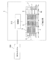
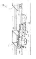
- FIG. 13 is an overall configuration diagram of a conventional medicine dispensing apparatus 100 (see, for example, Patent Document 1).
- the medicine dispensing device 100 includes a cassette 102 containing a medicine 104, a shelf 103 for storing the cassette, and a device 105 for taking out the medicine.
- the shelf 103 is divided into a large number of vertical and horizontal, and a plurality of cells 123 are formed. Each cell 123 stores a cassette 102 filled with a medicine 104.
- One cassette 102 is filled with, for example, several tens of medicines 104 of the same type.
- the apparatus 105 has an extraction unit 106 for taking out the medicine from the cassette 102.
- the take-out unit 106 is controlled by a predetermined control device and moves in the direction of the arrow 12A in the figure and the arrow 13A in the figure.
- the take-out unit 106 is positioned with respect to the cassette 102 containing the desired medicine 104 on the rear surface 3B of the storage shelf.
- the extraction unit 106 has a unit similar to a known robot arm (not shown). The robot arm takes out the medicine 104 from the cassette 102 and pays it out to the payout tray 141.
- the payout tray 141 is divided into a plurality of regions by a partition plate 142.
- the drug to be dispensed is dispensed to each area according to the application category.
- the dispensing tray 141 from which the medicine 104 has been dispensed is transported to an application place, for example, a ward.
- a tray which is a transporter, for each patient.
- the tray needs to display information identifying the patient. This is to ensure that the stored medicine or the like is correctly delivered to the patient or used correctly for the patient.
- a display label as a display means for identifying a tray that is a transporter.
- the display label is obtained by printing patient identification information or the like on a name tag paper or an adhesive label.
- the label is manually attached to the side of the tray and removed manually when the tray is finished.
- a rewrite card that can be repeatedly written is used for attaching and removing the display label due to a large work load (for example, Patent Document 2).
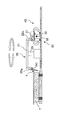
- FIG. 14 shows a conventional medicine dispensing apparatus 200 that automatically attaches a card as a display member to a tray in a detachable manner.
- the medicine dispensing apparatus 200 includes a card attachment / detachment transfer unit 210 and a writing unit 220.
- the card attaching / detaching / transferring unit 210 transfers the rewrite card 201 attached / detached to / from the tray T between the tray T and the writing unit 220.
- the writing unit 220 writes patient information to the rewrite card 201.
- the writing unit 220 is connected to the card attachment / detachment transfer unit 210.
- the rewrite card 201 attached to the tray T is removed by the card attaching / detaching / transferring means 210.
- the removed rewritable card 201 is sent between the rubber roller 212 and the plastic roller of the card attaching / detaching and transferring means 210 and transferred to the writing means 220.
- the transferred rewritable card 201 is printed by the writing means 220 and then sent again along the rubber roller 212 and the plastic roller, and attached to the tray T by the card attaching / detaching transferring means 210.
- the rewrite card In the card insertion / removal unit of the medicine dispensing device, the rewrite card is physically attached to the tray T. For this reason, there are cases where the card position is shifted during card insertion / removal or during conveyance, or the card cannot be accurately inserted into the writing means or the card holder of the tray. If the card holder of the tray does not originally have a rewrite card, the rewrite card must be manually replenished. In such a case, when the apparatus is temporarily stopped, it takes a long time for the apparatus to return to a normal state, and the medicine dispensing efficiency is deteriorated.
- a medicine dispensing apparatus is a medicine dispensing apparatus for dispensing a stored medicine to a transporter capable of mounting a card on which desired information is displayed. And a control unit.
- the card processing unit writes patient identification information on the card and attaches the card to the transporter.
- the label issuing unit displays patient identification information and issues a first label that is input to the transporter.
- the control unit causes the label issuing unit to issue the first label according to the state of the card processing unit.
- the drug is a drug that can be a subject of prescription, and includes, for example, injections, internal medicines, ointments, patches, suppositories, and the like.
- the patient identification information includes, for example, the patient name, ID number, sex, date of birth, department name, ward name, room number, and the like.
- the card processed in the card processing unit may be previously attached to each transporter, or may be taken out from the card storage unit or the like.
- the control unit selectively causes the label issuing unit to issue the first label according to the state of the card processing unit.
- a 1st label is a label which can be attached to a carrier instead of a card
- the control unit causes the label issuing unit not to issue the first label but only to issue the card by the card processing unit.
- the control unit determines whether or not to cause the label issuing unit to issue the first label.
- the card processing unit When the card processing unit is not in a normal state, for example, when an abnormality occurs in the card processing unit itself or when patient identification information cannot be displayed on the card, the card processing unit can remove the card from the portable device. This is the case when the card cannot be attached to the carrier.
- the medicine dispensing device is the medicine dispensing device according to the first invention, and the card is a rewrite card.
- the rewrite card is a rewritable card.
- the rewrite card is, for example, a leuco card that develops color by reacting and combining the leuco dye of the recording layer and the developer, or a so-called cloudy rewrite card.
- the leuco-type rewrite card utilizes the property of being colored (dye and developer are combined) when heated and cooled rapidly at high temperature, and erased (dye and developer are separated) when heated and cooled slowly at low temperature. Information can be rewritten.
- a rewritable card that can be rewritten is used.
- the card inserted into the transporter can be used as it is attached to the transporter as it is when the medicine is dispensed next time, so that the trouble of inserting the card again can be saved.
- the medicine dispensing device is the medicine dispensing device according to the first or second invention, wherein the label issuing unit further displays the identification information of the patient and the medicine application information for all the carriers. Issue a second label to be input.
- the drug application information includes the name of the drug applied to the patient, the amount of the drug, the application date and time, and the like.
- the second label may be issued integrally with the first label or may be issued separately.
- the label issuing unit always issues the second label and puts it in the tray, for example, it can also issue the first label additionally and put it into the transporter together with the second label. Therefore, even when the first label is issued according to the state of the card processing unit, it is not necessary to greatly change the control and operation in the label issuing unit.
- a medicine dispensing device is the medicine dispensing device according to any one of the first to third aspects, wherein the controller issues a label issuing unit when an abnormality occurs in the card processing unit. The first label is issued.
- the case where an abnormality occurs in the card processing unit includes, for example, a case where all or a part of the card processing unit performs an abnormal operation or stops during the operation.
- the control unit causes the label issuing unit to issue a first label. Accordingly, it is possible to reliably detect a case where the card attachment is likely to fail and to issue the first label to be attached to the tray instead of the card.
- a medicine dispensing apparatus is the medicine dispensing apparatus according to any one of the first to fourth aspects, wherein the card processing unit has a card detection unit for detecting a card at a predetermined position. Then, when the detection unit does not detect the card, the control unit causes the label issuing unit to issue the first label.
- the card detection unit is, for example, a photoelectric sensor or a CCD camera having a light projecting / receiving element.
- the predetermined position is, for example, the position of the card before being taken out of the transporter and displaying the patient identification information, or the position of the card before the patient identification information is displayed and attached to the transporter.
- the control unit recognizes that there is a high possibility that the card on which the patient identification information is displayed cannot be attached to the corresponding portable device.
- a first label can be issued in place of the card.
- a medicine dispensing apparatus is a medicine dispensing apparatus according to any one of the first to fifth inventions, and stores a spare card supplied to the card processing section.
- the control unit causes the card storage unit to supply a spare card to the card processing unit.
- the spare card is a card prepared separately from the card attached to the carrier.
- control unit supplies a spare card. This prevents a shortage of cards.
- the medicine dispensing apparatus is the medicine dispensing apparatus according to the sixth invention, and the control unit does not cause the label issuing unit to issue the first label when a spare card is supplied.
- the label issuing unit does not issue the first label. This can prevent frequent label issuance.
- the medicine dispensing apparatus according to the eighth invention is the medicine dispensing apparatus according to the sixth invention, and the control unit causes the label issuing unit to issue the first label when the spare card is supplied.
- the label issuing unit issues the first label.
- the first label attached to the tray is issued to improve safety.
- a medicine dispensing apparatus is the medicine dispensing apparatus according to the first or eighth invention, and further, when the first label is issued by the label issuing unit, the carrier that has issued the first label Means for removing the card attached to the.
- the card attached to the carrier on which the first label is issued by the label issuing unit is removed. This prevents the card and the first label from being duplicated on the transporter. Further, for example, even when wrong information or the like is displayed on the card processed in the card processing unit, or when an incorrect card is attached, the card can be removed for safety.
- a medicine dispensing method is a medicine dispensing method for dispensing a stored medicine to a portable device capable of mounting a card on which desired information is displayed.
- a step and a control step In the card processing step, patient identification information is entered on the card, and the card is attached to the carrier.
- the label issuance step the patient's identification information is displayed and a first label to be inserted into the carrier is issued.
- the label issuing step is executed to issue the first label.
- control step executes the label issuing step according to the state in the card processing step to issue the first label.
- identification information can be given more reliably and quickly to the transporter from which the medicine is dispensed, and the efficiency of dispensing the medicine can be improved.
- medicine is a drug that can be a subject of prescription, and includes, for example, injections, internal medicines, ointments, patches, suppositories, and the like.
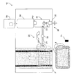
- FIG. 1 shows the appearance of a drug dispensing device 1 according to this embodiment.
- the drug dispensing device 1 performs a drug dispensing process according to patient identification information, drug application information, prescription information, and the like. As shown in FIG. 2, the medicine dispensing apparatus 1 also collects a rewrite card RC before rewriting (hereinafter referred to as a pre-print rewrite card RC) from each tray (carrying device) T that is carried in, and at the same time, performs card processing.
- a rewrite card RC after rewriting (hereinafter referred to as a rewrite card RC after printing) is automatically attached by the unit 10 (FIG. 2).
- the identification information of each patient, medication application information, prescription information, and the like are transmitted from the electronic medical chart system 300 to a management device 310 such as a server.
- the patient identification information includes, for example, the patient's name, ID number, gender, date of birth, department name, ward name, room number, etc.
- the contents include a rewrite card RC, a tray label L1, an application label L2, and a prescription. Etc. (FIG. 15).
- the drug application information includes the name and dose of the drug applied to the patient, the date and time when the drug is applied, and the contents are mainly displayed on the application label L2.
- the prescription information is the contents described in the prescription, and includes, in addition to the patient identification information, the name of the medicine to be prescribed and its dose, the application date and time, the single application amount, the application method, and the like. Note that these pieces of information are not strictly divided, and may be partially or entirely duplicated.
- Each tray T to be conveyed is an A4 or A3 size container.
- a rewrite card RC before printing is attached to the card holder 4 (FIG. 3) on each tray T before conveyance.
- the card holder 4 is attached to one end surface of the tray T on the card processing unit 10 side, as shown in FIG. As shown in the figure, the card holder 4 is formed such that the upper part is inclined toward the card processing unit 10 with respect to the vertical surface of the tray T.
- the card holder 4 has an opening at the top, and the rewrite card RC is inserted through the opening. Note that the card holder 4 may be opened on the side so that the rewrite card RC can be inserted from the side.
- Rewrite card RC is a rewritable card.
- the rewrite card is, for example, a leuco card that develops color by reacting and combining the leuco dye of the recording layer and the developer, or a so-called cloudy rewrite card.
- the leuco-type rewrite card utilizes the property of being colored (dye and developer are combined) when heated and cooled rapidly at high temperature, and erased (dye and developer are separated) when heated and cooled slowly at low temperature.
- Information can be rewritten.
- another card-like object whose display can be changed may be used. As shown in FIG. 15 (a), patient identification information is mainly printed on the rewrite card RC.
- the medicine dispensing apparatus 1 includes, as main components, a tray supply unit 2, a medicine dispensing unit 3, a tray conveyance path P, a label / prescription issuing unit (label issuing unit) 6 (FIG. 7), and a completed tray stacking.
- a unit 7 and a card processing unit (card processing unit) 10 are provided.
- the medicine dispensing device 1 includes a device control unit 5 and a management device 310 (FIG. 8) as a control unit, and controls each unit.
- the tray supply unit 2 sends out the stacked trays T one by one to the tray conveyance path P in response to a command from the device control unit 5 of the medicine dispensing device 1.
- the tray T is transported in the direction of the arrow in FIG. 1 along the tray transport path P, and temporarily stops at a predetermined position near the medicine dispensing unit 3.
- the medicine dispensing unit 3 is arranged on the downstream side of the tray supply unit 2 so as to face the conveyance path P.
- the medicine dispensing unit 3 includes medicine storage means such as a cassette for storing medicine and a drawer, and pick-up means for automatically taking out medicine from the medicine storage means and dispensing it into the tray T.
- the medicine is put in a container such as an ampoule, a vial, a plastic bottle, a kit, or a bag, and is stored in advance in the medicine storage means.
- the pickup means is composed of a robot arm or the like.
- the pick-up means picks up a drug in accordance with a command from the apparatus control unit 5 based on the identification information and prescription information of each patient, and dispenses it to the tray T.
- the card processing unit 10 is arranged on the downstream side of the medicine dispensing unit 3 so as to face the conveyance path P. As will be described later, the card processing unit 10 takes out the rewrite card RC before printing on the tray T and automatically attaches the rewrite card RC after printing to the tray T. The detailed configuration of the card processing unit 10 will be described in detail later.
- the label / prescription issuing unit 6 is disposed above the card processing unit 10 as shown in FIG.
- the label / prescription issuing unit 6 prints the application label L2 (second label) and the prescription, selectively prints the tray label L1 (first label), and puts it in the tray T.
- the detailed configuration of the label / prescription issuing unit 6 will be described in detail later.
- patient identification information is mainly printed on the tray label L1 in the same manner as the rewrite card RC.
- the application label L2 is printed with the application information of a medicine in addition to patient identification information.
- the tray label L1 and the enforcement label L2 may be printed on a single sheet that can be divided, or may be printed on separate sheets.
- the completed tray stacking unit 7 loads and holds the tray T to which the medicine, the post-printing rewrite card RC (or tray label L1), the application label L2, and the prescription are supplied.
- the loaded tray T is carried out by a cart.
- the medicine in the tray T carried out by the cart is prescribed to the patient through a drug inspection process.
- the medicine dispensing device 1 includes a device control unit 5 (FIG. 8) and a management device 310 that function as a control unit.
- the apparatus control unit 5 is a computer that controls the medicine dispensing apparatus 1, and includes a tray supply unit 2, a medicine dispensing unit 3, a tray conveyance path P, a label / prescription issuing unit 6, a completed tray stacking unit 7, and a card processing unit. 10 etc. are controlled.
- the management device 310 is a computer that controls the medicine dispensing device 1.
- the management device 310 receives identification information of each patient, medication application information, prescription information, and the like from the electronic medical record system 300. Based on the request or the like, a rewrite card RC, tray label L1, application label L2, prescription issuance command, or rewrite card RC supply command is issued.
- the medicine dispensing apparatus 1 according to the present embodiment will be described with a focus on the control of the card processing unit 10 and the label / prescription issuing unit 6 which are characteristic parts of the present invention.
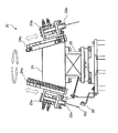
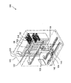
- FIG. 2 is a diagram schematically showing the card processing unit 10.
- the card processing unit 10 prints patient identification information on the pre-print rewrite card RC, and automatically attaches the post-print rewrite card RC to the tray T on which the medicine is loaded.
- the card processing unit 10 provides means for more reliably detaching the rewrite card RC from the tray T and reducing the time during which the tray T is stopped as much as possible.
- the card processing unit 10 includes a handling mechanism 20, a card transfer mechanism 30, a card position regulation mechanism 40, a card printing mechanism 50, and a card stocker (card storage unit) 70.
- the handling mechanism 20 is arranged facing the tray conveyance path P.
- the handling mechanism 20 exchanges the pre-print rewrite card RC inserted in the card holder 4 of the tray T with the post-print rewrite card RC held in the card transfer mechanism 30.
- the card transfer mechanism 30 is arranged behind the handling mechanism 20.
- the card transfer mechanism 30 holds the rewrite card RC, reverses the front and back as necessary, and inserts or removes the rewrite card RC from the card printing mechanism 50.
- the card position regulating mechanism 40 is arranged in an L shape with respect to the handling mechanism 20 as shown in FIG.
- the card position regulating mechanism 40 positions the planar rewrite card RC so as to sandwich both sides and corners of the rewrite card RC placed along a substantially horizontal direction.
- the card printing mechanism 50 is arranged so as to be connected to the card position adjusting mechanism 40, and together with the card position adjusting mechanism 40, forms a transfer path for the rewrite card RC parallel to the tray transport path P.
- the card printing mechanism 50 prints patient identification information on the pre-print rewrite card RC.
- the card stocker 70 is arranged following the card printing mechanism 50, and forms a transfer path for the rewrite card RC parallel to the tray transport path P together with the card position regulating mechanism 40 and the card printing mechanism 50.
- the card stocker 70 accommodates a spare pre-print rewrite card RC and supplies the pre-print rewrite card RC to the card printing mechanism 50 as necessary.
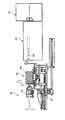
- the handling mechanism 20 includes an arm 21, a pair of card gripping portions 22a and 22b, a pair of support portions 23a and 23b, a pair of guide portions 24a and 24b, a vertical rotation shaft 25, A first card sensor (card detection unit) 26 and a third card sensor 27 are included.
- the center of the arm 21 is supported by a vertical rotation shaft 25, and card holding portions 22a and 22b are formed at both ends.
- the card gripping portions 22a and 22b are provided at both ends of the arm 21, and are formed so as to sandwich the edge portion of the rewrite card RC.
- the card gripping portions 22a and 22b are also formed so as to incline toward the vertical rotation shaft 25 in accordance with the card holder 4 of the tray T.
- the support portions 23a and 23b support the card gripping portions 22a and 22b, and are formed to be movable up and down along the guide portions 24a and 24b together with the card gripping portions 22a and 22b, as indicated by arrows in FIG.
- the support portions 23a and 23b are also formed so as to incline toward the vertical rotation shaft 25, similarly to the card gripping portions 22a and 22b.
- the guide portions 24 a and 24 b support the support portions 23 a and 23 b on the arm 21.
- the guide portions 24a and 24b are also formed so as to incline toward the vertical rotation shaft 25 as with the card gripping portions 22a and 22b and the support portions 23a and 23b.
- the vertical rotation shaft 25 supports the center of the arm 21 and has an axis substantially perpendicular to the apparatus installation surface.
- the vertical rotation shaft 25 is formed to be rotatable about the same axis as indicated by the arrow in FIG.
- the first card sensor 26 is provided so as to face the conveyance path P.
- the first card sensor 26 is, for example, a photoelectric sensor having a light projecting / receiving element.
- the first card sensor 26 mainly checks the presence or absence of the rewrite card RC in the card holder 4.
- the first card sensor 26 can detect, for example, the case where the rewrite card RC before printing is not in the card holder 4 or the case where the rewrite card RC after printing is dropped before being inserted into the card holder 4.
- the third card sensor 27 can detect a case where the card gripping portions 22 a and 22 b have missed and dropped the pre-printing rewrite card RC in the card holder 4.
- the first and third card sensors 26 and 27 send an error signal to the apparatus control unit 5 when the rewrite card RC cannot be detected.
- the apparatus control unit 5 issues a print request for the tray label L1 to the management apparatus 310 or a supply request for the rewrite card RC before printing, as will be described later.
- the handling mechanism 20 operates as follows. In response to a command from the device control unit 5, a drive unit (not shown) such as a motor is driven, and the support units 23a and 23b are lowered along the guide units 24a and 24b.
- the card gripping portions 22a and 22b that are lowered together with the support portions 23a and 23b are arranged so that the pre-printing rewrite card RC stored in the card holder 4 of the tray T and the post-printing rewrite card RC held by the card transfer mechanism 30 respectively. Hold it.
- the support portions 23a and 23b rise along the guide portions 24a and 24b.
- the vertical rotation shaft 25 rotates 180 degrees. After this rotation, the support portions 23a and 23b are lowered. Then, the card gripping portion 22a passes the rewrite card RC before printing to the card transfer mechanism 30, and the card gripping portion 22b inserts the rewrite card RC after printing into the card holder 4 of the tray T.
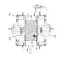
- the card transfer mechanism 30 includes a card holding part 31, a support part 32, a horizontal rotation shaft 33, an upper and lower guide part 34, and a front and rear guide part 35.
- the card holding unit 31 is formed to be rotatable about the horizontal rotation shaft 33 and holds the rewrite card RC.
- the support portion 32 is formed to support the card holding portion 31 above the card position adjusting mechanism 40.
- the support portion 32 is further configured to move up and down by an up and down guide portion 34 and to be movable back and forth by a front and back guide portion 35.
- the horizontal rotation shaft 33 has an axis substantially parallel to the apparatus installation surface, and is formed to be rotatable about the same axis.
- the vertical guide portion 34 is formed so as to guide the support portion 32 in the vertical direction of FIG.
- the front / rear guide part 35 is formed to guide the support part 32 in the front / rear direction of FIG. 5, that is, in the forward / backward direction with respect to the card printing mechanism 50.
- the card transfer mechanism 30 operates as follows.
- the card holding unit 31 receives the pre-print rewrite card RC held in an inclined state by the card holding units 22 a and 22 b of the handling mechanism 20.
- the card holding unit 31 is driven and rotated about the horizontal rotation shaft 33 to bring the rewritable card RC into a horizontal state, and then the support unit 32 is lowered by the driven upper and lower guide units 34, whereby the rewritable card is driven.
- RC is set in the card position adjusting mechanism 40.
- the second card sensor (card detection unit) 42 (FIG. 6) of the card position regulating mechanism 40 senses the pre-print rewrite card RC.
- the second card sensor 42 transmits a card detection signal to the device controller 5.
- the device controller 5 issues a command to the card transfer mechanism 30.
- the apparatus controller 5 also reverses the front and back of the pre-print rewrite card RC by the card transfer mechanism 30 when necessary.
- the card holding unit 31 releases the holding of the pre-print rewrite card RC, and the pre-print rewrite card RC is positioned by the card position adjusting mechanism 40. After holding the pre-printed rewrite card RC whose position has been corrected by the card holding unit 31, the card position correction is released.
- the support unit 32 In the state where the card holding unit 31 holds the rewrite card RC before printing horizontally, the support unit 32 is raised by the driven vertical guide unit 34. Furthermore, the support part 32 advances toward the card printing mechanism 50 by the driven front and rear guide part 35. After the card holding unit 31 releases the holding of the pre-print rewrite card RC, the pre-print rewrite card RC is inserted into the card printing mechanism 50 as indicated by a virtual line in FIG.
- the card printing mechanism 50 ejects the card, and the card holding unit 31 holds the rewrite card RC after printing.
- the support portion 32 is retracted by the driven front / rear guide portion 35 to remove the rewritable card RC from the card printing mechanism 50 after printing.
- the support portion 32 is lowered by the driven vertical guide portion 34, and sets the rewrite card RC after printing to the card position adjusting mechanism 40.
- the card holding unit 31 releases the holding of the rewritable card RC after printing, and the rewritable card RC after printing is positioned by the card position regulating mechanism 40. After the rewritten post-printing rewritten card RC is held by the card holding unit 31, the card position correction is released.
- the card holding unit 31 is driven and rotated around the horizontal rotation shaft 33 to hold the rewritable card RC after printing in an inclined state as shown in FIG. 4 from the horizontal state, and to the card holding units 22a and 22b of the handling mechanism 20. hand over.
- the front / back direction when the rewritten card RC is passed to the handling mechanism 20 and the front / back direction of the pre-printed rewrite card RC when inserted into the card printing mechanism 50 are determined in advance.
- the card transfer mechanism 30 reverses the rewrite card RC as needed based on information on the front and back directions determined in advance and a signal from the second card sensor 42.
- the card position regulation mechanism 40 includes first position regulation parts 41 a and 41 a, second position regulation parts 41 b and 41 b, and a second card sensor 42.
- the first position setting parts 41a and 41a are arranged in a plan view so as to sandwich the corners of the rewrite card RC placed along the substantially horizontal direction. Position in the left / right and front / rear direction. Furthermore, the second position restricting portions 41b and 41b perform the left and right positioning of the rewrite card RC in a plane so as to sandwich the long side of the rewrite card RC.
- the second card sensor 42 is a photoelectric sensor having a light projecting / receiving element.
- a three color (red, blue, green) LED light source is used for the light projecting element, and the detection object is irradiated with spot light.
- This is a color sensor that performs color discrimination by analyzing a color component of light received by reflection from the light.
- the second card sensor 42 senses the rewrite card RC and transmits a signal to the device controller 5.
- the device control unit 5 determines the presence and front / back direction of the rewrite card RC from the transmitted signal.
- the second card sensor 42 is a CCD camera, and the presence and the front / back direction of the rewrite card RC may be determined by recognizing the image obtained by the device control unit 5.
- Card printing mechanism 50 The card printing mechanism 50 prints predetermined information on the rewrite card RC based on the patient identification information in accordance with a command from the management device 310, and creates a rewritten card RC after printing.
- the card printing mechanism 50 includes, for example, a heat energy application unit such as a heat roller or a thermal head inside, and applies heat energy at a predetermined temperature to the information display surface of the inserted rewrite card RC, thereby providing an information display surface. It is a device that erases and writes information. Such a rewritable card printing apparatus is well known, and therefore, detailed description thereof is omitted.
- Card stocker 70 The card stocker 70 stores a spare rewrite card RC.
- the device controller 5 issues a supply request for the pre-print rewrite card RC to the management device 310. Output to.
- the management device 310 issues a pre-print rewrite card RC supply request command to the card printing mechanism 50.
- the card printing mechanism 50 requests the rewrite card RC from the card stocker 70 in response to the command. As a result, the rewrite card RC is supplied to the card printing mechanism 50.
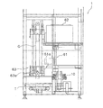
- the label / prescription issuing unit 6 inputs a label printing mechanism 61 for printing the labels L1, L2, a prescription printing mechanism 62 for printing the prescription, and the printed prescription and the labels L1, L2. And a charging mechanism 63.
- the label printing mechanism 61 is arranged above the card processing unit 10 and normally issues an application label L2 in which drug application information is described.
- an error occurs in the card processing unit 10, in addition to the application label L2, patient identification information Is displayed and a tray label L1 in place of the rewrite card RC is issued.
- the prescription printing mechanism 62 is disposed above the label printing mechanism 61 as shown in FIG.
- the prescription printing mechanism 62 issues a prescription corresponding to the patient's prescription information to each tray T.
- the input mechanism 63 moves the pocket portion 63a up and down.
- the pocket part 63a receives the prescription from the prescription printing mechanism 62, receives the application label L2 from the label printing mechanism 61, and puts it in the tray T.
- the pocket portion 63a also moves up and down in response to a command from the device control unit 5 that has received an error signal as will be described later, and a tray label L1 printed with patient identification information from the label printing mechanism 61 in the same manner as the rewrite card RC. Is put into the tray T.
- Label printing mechanism 61 Normally, the label printing mechanism 61 prints the applied label L2 in response to a printing command from the management device 310. After printing, the applied label L2 is primarily held in the label pocket 61a from the discharge port of the label printing mechanism 61, and then placed in the pocket portion 63a of the loading mechanism 63. The application label L2 is supplied to all trays T.
- the label pocket 61a temporarily holds the application label L2 issued while the pocket portion 63a of the loading mechanism 63 receives the prescription from the prescription printing mechanism 62.
- the label printing mechanism 61 prints the tray label L1 used in place of the rewrite card RC in response to the occurrence of an error in the card processing unit 10 in addition to the normal issuance of the application label L2.
- the label printing mechanism 61 in this case operates in response to a tray label L1 issuance command from the management device 310, as will be described later.
- the tray label L1 is manually attached to the tray T at the time of drug inspection after the tray T is carried out. On the tray label L1, patient identification information is printed.
- both labels L1 and L2 are primarily held in the label pocket 61a from the discharge port of the label printing mechanism 61. Thereafter, both labels L1 and L2 are put in the pocket portion 63a of the loading mechanism 63 and supplied to the tray T. Even when an error occurs during printing of the application label L2, the same processing as described above is performed.
- the application label L2 is supplied to the tray T by the same process as described above. During this time, the printing of the tray label L1 is completed, and then the tray label L1 is primarily held in the label pocket 61a from the discharge port of the label printing mechanism 61. Thereafter, the tray label L1 is placed in the pocket portion 63a of the loading mechanism 63 and supplied to the tray T.
- Prescription printing mechanism 62 The prescription printing mechanism 62 issues a prescription sheet on which patient prescription information is printed. The issued prescription is put into the pocket portion 63a of the loading mechanism 63 and is loaded into the trays T of all patients.
- the throwing mechanism 63 has a guide part G extending in the vertical direction in FIG. 7 and a pocket part 63a that moves up and down along the guide part G.
- the pocket portion 63a of the loading mechanism 63 is disposed so as to face the label printing mechanism 61 and the prescription printing mechanism 62, and moves up and down along the guide portion G by a driving source such as a motor.
- the pocket portion 63a receives the labels L1, L2 and the prescription from the label printing mechanism 61 and the prescription printing mechanism 62, and puts them into the tray T.
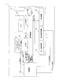
- FIG. 8 is a control block diagram showing the relationship among the device control unit 5, the card processing unit 10, the label / prescription issuing unit 6, and the management device 310 of the medicine dispensing device 1.
- the device control unit 5 controls the operation of each mechanism of the card processing unit 10 and the label / prescription issuing unit 6.
- the device control unit 5 commands the operation based on a predetermined condition judgment, particularly for the label printing mechanism 61 and the loading mechanism 63 of the label / prescription issuing unit 6.
- the device control unit 5 receives the rewrite card from the sensor of the card processing unit 10 (the first card sensor 26 of the handling mechanism 20, the third card sensor 27 and the second card sensor 42 of the card position regulating mechanism 40). A signal for sensing RC is received. The apparatus control unit 5 also receives an error signal from the card processing unit 10 and transmits a rewrite card RC supply request and a tray label L1 print request to the management apparatus 310.
- the management apparatus 310 receives patient identification information, medicine application information, prescription information, and the like from the electronic medical chart system 300 (FIG. 1), and issues a command to the medicine dispensing apparatus 1 based on these information.
- the management device 310 causes the card stocker 70 to supply the rewrite card RC via the card printing mechanism 50 in response to the rewrite card RC supply request from the device control unit 5.
- the management device 310 also outputs a print command for the rewrite card RC to the card printing mechanism 50.
- the management device 310 outputs an operation command to the label printing mechanism 61 in response to a print request for the tray label L1 from the device control unit 5 to print the tray label L1.
- the management device 310 Normally, the management device 310 outputs an operation command for printing the application label L2 to the label printing mechanism 61. Further, the management device 310 outputs an operation command for printing a prescription corresponding to the prescription information to the prescription printing mechanism 62.
- the management device 310 transmits and receives barcode information and patient identification information (link information) to and from the device control unit 5. Specifically, the management device 310 receives the barcode information (tray identification information) of the tray T read by the barcode reader (not shown) of the medicine dispensing unit 3 via the device control unit 5. The management device 310 generates link information that associates the barcode information with the patient identification information and the drug information based on the patient prescription information, and transmits the link information to the device control unit 5. The device control unit 5 stores the link information in the memory. The device control unit 5 also transmits a medicine dispensing instruction to the medicine dispensing unit 3.
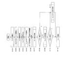
- FIG. 9 shows that the medicine dispensing apparatus 1 carries in the tray T in accordance with a command from the management apparatus 310, dispenses the medicine, collects the rewrite card RC before printing from the tray T, and then collects the rewrite card after printing on the tray T.
- a flow of a series of processes from attaching the RC, putting the prescription and the application label L2 into the tray T, and carrying out the tray T is shown.
- the tray label L1 is inserted instead of the rewrite card RC after printing.
- the pre-print rewrite card RC mounted in advance on each tray T is printed with patient identification information corresponding to the medicine dispensed to the next tray T. Therefore, each tray T is attached with the post-printing rewrite card RC on which the identification information of the patient corresponding to the medicine dispensed to the tray T is already printed out at the same time that the pre-printing rewrite card RC that has been attached is extracted. It will be. As a result, the waiting time of the tray T is shortened, and the conveyance efficiency is improved.
- Step S101 First, the tray T is carried into the medicine dispensing unit 3 from the tray supply unit 2.
- Step S102 The barcode information (tray identification information) of the tray T is read by the barcode reader (not shown) of the medicine dispensing unit 3 and transmitted to the management device 310.
- the link information is stored in the memory of the device control unit 5.
- Step S104 Drugs are sequentially dispensed to the tray T based on the drug information of the patient.
- Step S105 When the medicine dispensing immediately before the card processing unit 10 in the medicine dispensing unit 3 is completed, the barcode information on the tray T is read by the barcode reader 71 (FIG. 2) and transmitted to the management device 310. At this point, a request for issuing the rewrite card RC is issued.
- Step S106 The management device 310 creates card printing data based on the patient identification information corresponding to the barcode information.
- the card printing data is output to the card printing mechanism 50.
- Step S107 Card issuing processing is performed by the card processing unit 10 (steps S1001 to S1011).
- Step S108 If an error signal is transmitted in the card issuing process, the process proceeds to step S111. If an error signal is not transmitted, the process proceeds to step S109.
- the case where the error signal is transmitted is a case where the rewrite card RC is not supplied from the card stocker 70. Furthermore, if any of the mechanisms of the card processing unit 10 has an abnormality and cannot be printed on the rewrite card RC, if there is an abnormality in the printing of the rewrite card RC, or if the transfer of the rewrite card RC fails, an error will occur. A signal is emitted.
- Step S109 Card replacement processing is performed by the card processing unit 10 (steps S1071 to S1078).
- Step S110 If an error signal is transmitted in the card replacement process, the process proceeds to step S111. If an error signal is not transmitted, the process proceeds to step S112.
- the case where the error signal is transmitted is a case where the rewriting card RC after printing cannot be attached to the tray T by the handling mechanism 20. Furthermore, an error signal is also transmitted when there is an abnormality in any mechanism of the card processing unit 10 and the rewrite card RC is not normally attached to the tray T after printing.
- S111 step The tray label L1 issuance process is performed (steps S1091 to S1092).
- Step S112 The tray T on which the rewrite card RC is attached after printing or the tray T on which the tray label L1 is inserted is carried out.
- FIG. 10 shows the flow of card issuance processing by the card processing unit 10.
- Step S1001 When the second card sensor 42 of the card position adjusting mechanism 40 detects the rewrite card RC set in the card position adjusting mechanism 40, a signal is transmitted to the apparatus control unit 5. If the rewrite card RC is detected, the process proceeds to step S1002, and if the rewrite card RC is not detected, the process proceeds to step S1006.
- Step S1002 The device control unit 5 further determines the front and back of the rewrite card RC from the signal of the second card sensor 42. If the front and back direction of the rewrite card RC is not as specified, the process proceeds to step S1003, and if it is as specified, the process proceeds to step S1004.
- Step S1003 The card transfer mechanism 30 reverses the front and back of the rewrite card RC and sets the card position adjusting mechanism 40 again.
- Step S1004 After the card transfer mechanism 30 releases the grip of the rewrite card RC, the position of the rewrite card RC is regulated by the card position regulation mechanism 40.
- Step S1005 The pre-printing rewrite card RC whose position is regulated is gripped by the card transfer mechanism 30 and inserted into the card printing mechanism 50.
- Step S1006 On the other hand, if the rewrite card RC is not detected by the second card sensor 42, the device control unit 5 outputs a supply request for the rewrite card RC before printing to the management device 310.
- the management device 310 issues a supply command for the pre-print rewrite card RC to the card printing mechanism 50 in response to the request. In response to this command, the card stocker 70 supplies a spare rewrite card RC to the card printing mechanism 50.
- Step S1007 If the spare rewrite card RC cannot be supplied from the card stocker 70, the process proceeds to step S1008. If the rewrite card RC can be supplied, the process proceeds to step 1009.
- Step S1008 The card processing unit 10 transmits an error signal to the device controller 5.
- Step S1009 The card printing data created by the management device 310 is printed on the rewrite card RC by the card printing mechanism 50.
- Step S1010 The rewrite card RC is extracted from the card printing mechanism 50 by the card transfer mechanism 30.
- Step S1011 After the card transfer mechanism 30 releases the grip of the rewrite card RC, the position of the rewrite card RC is regulated by the card position regulation mechanism 40. Thereafter, it is gripped by the card transfer mechanism 30 and transferred to the handling mechanism 20 (step S1072).
- FIG. 11 shows a flow of card replacement processing by the card processing unit 10.
- Step S1071 The rewrite card RC before printing in the card holder 4 of the tray T is gripped by one card gripping portion 22a of the handling mechanism 20 of the card processing unit 10.
- Step S1072 At the same time, the post-print rewrite card RC held by the card transfer mechanism 30 is gripped by the other card gripping portion 22b of the handling mechanism 20.
- Step S1073 The handling mechanism 20 rotates 180 degrees.
- the card gripping portion 22a moves to the card position regulating mechanism 40 side, and the card gripping portion 22b moves to the tray T side.
- Step S1074 The rewritable card RC after printing is inserted into the card holder 4 of the tray T by the card gripping portion 22b.
- Step S1075 On the tray T side, the first card sensor 26 senses the rewrite card RC after printing and transmits it to the apparatus control unit 5. If the rewrite card RC is detected after printing, the process ends. If the rewrite card RC is not detected after printing, the process proceeds to step S1076.
- Step S1076 The apparatus control unit 5 transmits an error signal.
- Step S1077 On the other hand, on the card position regulating mechanism 40 side, the pre-print rewrite card RC is delivered to the card transfer mechanism 30 from the card gripping portion 22a.
- Step S1078 The rewrite card RC before printing is set in the card position adjusting mechanism 40 by the card transfer mechanism 30.
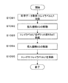
- FIG. 12 shows a flow of the issuing process of the tray label L1 by the label / prescription issuing unit 6.
- Step S1091 In response to the print request for the tray label L1 from the apparatus control unit 5, the management apparatus 310 outputs the patient identification information of the error target tray T to the label printing mechanism 61 as tray label data.
- the label printing mechanism 61 creates the tray label L1 by printing the tray label data.
- Step S1092 Next, the input mechanism 63 is driven to align the pocket portion 63a with the position of the label printing mechanism 61.
- Step S1093 The label printing mechanism 61 supplies the tray label L1 primarily held in the label pocket 61a to the pocket portion 63a of the loading mechanism 63.
- Step S1094 Next, the loading mechanism 63 is driven, and the pocket portion 63a reaches the loading position on the tray T.
- Step S1095 The tray label L1 is supplied to the tray T from the pocket portion 63a.
- the label printing mechanism 61 normally prints the application label L 2 and puts it on the tray T by the feeding mechanism 63 together with the prescription printed by the prescription printing mechanism 62.
- the tray label L1 issuance process is performed when an error occurs in the card processing unit 10 in addition to the normal process.
- the types of errors are not limited to those described above.
- an abnormal operation or an unexpected stop of each mechanism of the card processing unit 10 may be detected and an error may be issued, and the tray label L1 may be issued.
- a card processing unit 10 that issues a rewrite card RC attached to the tray T, and a label / prescription issuing unit 6 that normally issues an application label L2 and a prescription, If an error occurs in the card processing unit 10, the label / prescription issuing unit 6 is made to issue a tray label L1 in place of the rewrite card RC in addition to the applied label L2.
- the tray label L1 can be issued instead of the rewrite card RC.
- the payout efficiency can be improved.
- the medicine dispensing apparatus 1 when the first card sensor 26 does not detect the rewrite card RC after printing, an error signal is transmitted. Accordingly, it is possible to reliably detect a case where the rewrite card RC is likely to fail to be attached and to issue the tray label L1.
- the card stocker 70 is provided, and when the pre-print rewrite card RC is insufficient, the pre-print rewrite card RC is supplied from the card stocker 70. Thereby, it is possible to cope with the shortage of the rewrite card RC before printing. Further, in this case, since the tray label L1 is not issued, frequent occurrence of the tray label L1 can be prevented.
- the medicine dispensing apparatus 1 also issues a tray label L1 when an abnormality occurs in the card processing unit 10 itself. Accordingly, it is possible to reliably detect a case where the rewrite card RC is likely to fail to be attached and to issue the tray label L1.
- the rewrite card RC is a rewrite card
- the rewrite card RC is used as it is as the pre-print rewrite card RC at the next payout. it can.
- tray label L1 may be issued also in the following cases.
- the tray label L1 is displayed regardless of whether or not the rewrite card RC is supplied from the card stocker 70. Can be issued.
- the identification information of the tray T can be more reliably attached to the tray T. Therefore, it is possible to avoid the risk that the tray T cannot be identified or the tray T is erroneously identified, and the safety is improved.
- the card stocker 70 may not be equipped. Further, when the rewrite card RC is attached but the tray label L1 is also inserted, means for removing the rewrite card RC from the tray T may be provided. This prevents the rewrite card RC and the tray label L1 from being redundantly applied to the tray T. Further, for example, even when wrong information or the like is displayed on the rewrite card RC processed in the card processing unit 10 or when the wrong rewrite card RC is attached, the card is removed for safety. Can do.
- the tray label L1 is issued instead of the rewrite card RC, but both the rewrite card RC and the tray label L1 after printing are issued. Good. Thereby, even when the rewritable card RC after printing is removed on the transport path P, a means for reliably identifying the patient can be provided.
- control unit 5 and the management device 310 are provided as the control unit, but the present invention is not limited to this mode. Some or all of the respective controls may be performed by the other device, or a single device may be provided separately or integrally to perform all the controls.
- the positions of the first card sensor 26 and the third card sensor 27 of the handling mechanism 20 of the card processing unit 10 and the position of the second card sensor 42 of the card position adjusting mechanism 40 are not limited to those of the above embodiment.
- the number of card sensors may be one or three or more. Further, the device control unit 5 may determine the presence / absence of the rewrite card RC before printing or the rewrite card RC after printing based on signals from a plurality of card sensors at different positions.
- the tray T which is a carrier, is transported with the rewrite card RC attached, but the rewrite card RC supplied from the card stocker 70 or the like is transferred by the card processing unit 10. You may make it attach.
- the present invention is useful as a medicine dispensing apparatus and a medicine dispensing method because it provides the effect of giving identification information more reliably and promptly to the transporter from which the medicine is dispensed and improving the efficiency of dispensing the medicine.
Landscapes
- Health & Medical Sciences (AREA)
- General Physics & Mathematics (AREA)
- Engineering & Computer Science (AREA)
- Physics & Mathematics (AREA)
- General Health & Medical Sciences (AREA)
- Epidemiology (AREA)
- Medicinal Chemistry (AREA)
- Medical Informatics (AREA)
- Primary Health Care (AREA)
- Public Health (AREA)
- Bioinformatics & Cheminformatics (AREA)
- Chemical & Material Sciences (AREA)
- Medical Preparation Storing Or Oral Administration Devices (AREA)
- Auxiliary Devices For And Details Of Packaging Control (AREA)
- Basic Packing Technique (AREA)
Priority Applications (2)
| Application Number | Priority Date | Filing Date | Title |
|---|---|---|---|
| EP09814256.5A EP2327388A4 (en) | 2008-09-19 | 2009-09-11 | DRUG ADMINISTRATIVE DEVICE AND MEDICINE ADMINISTRATIVE PROCEDURE |
| US12/995,811 US8521325B2 (en) | 2008-09-19 | 2009-09-11 | Drug delivery device and drug delivery method |
Applications Claiming Priority (2)
| Application Number | Priority Date | Filing Date | Title |
|---|---|---|---|
| JP2008-241839 | 2008-09-19 | ||
| JP2008241839A JP5208640B2 (ja) | 2008-09-19 | 2008-09-19 | 薬剤払出装置および薬剤払出方法 |
Publications (1)
| Publication Number | Publication Date |
|---|---|
| WO2010032411A1 true WO2010032411A1 (ja) | 2010-03-25 |
Family
ID=42039261
Family Applications (1)
| Application Number | Title | Priority Date | Filing Date |
|---|---|---|---|
| PCT/JP2009/004546 Ceased WO2010032411A1 (ja) | 2008-09-19 | 2009-09-11 | 薬剤払出装置および薬剤払出方法 |
Country Status (4)
| Country | Link |
|---|---|
| US (1) | US8521325B2 (enExample) |
| EP (1) | EP2327388A4 (enExample) |
| JP (1) | JP5208640B2 (enExample) |
| WO (1) | WO2010032411A1 (enExample) |
Cited By (2)
| Publication number | Priority date | Publication date | Assignee | Title |
|---|---|---|---|---|
| CN102883700A (zh) * | 2010-05-07 | 2013-01-16 | 松下电器产业株式会社 | 药品自动分配装置 |
| JP2024149652A (ja) * | 2013-11-22 | 2024-10-18 | 株式会社湯山製作所 | 薬剤払出し装置 |
Families Citing this family (2)
| Publication number | Priority date | Publication date | Assignee | Title |
|---|---|---|---|---|
| JP5389006B2 (ja) * | 2010-12-24 | 2014-01-15 | 株式会社トーショー | 薬剤情報印刷投入装置 |
| JP7118377B2 (ja) * | 2019-04-12 | 2022-08-16 | 株式会社トーショー | 薬剤情報印刷投入装置 |
Citations (6)
| Publication number | Priority date | Publication date | Assignee | Title |
|---|---|---|---|---|
| JPH0788156A (ja) * | 1993-09-22 | 1995-04-04 | Tokyo Shokai:Kk | 注射薬調剤機 |
| JP2005161736A (ja) * | 2003-12-04 | 2005-06-23 | Hitachi Omron Terminal Solutions Corp | カード取扱装置 |
| JP2005279268A (ja) | 2005-03-22 | 2005-10-13 | Yuyama Manufacturing Co Ltd | 薬剤払出装置 |
| JP3722695B2 (ja) * | 2000-12-26 | 2005-11-30 | アロカ株式会社 | 採血業務支援システム |
| JP2006109900A (ja) | 2004-10-12 | 2006-04-27 | Matsushita Electric Ind Co Ltd | 注射薬自動払出装置 |
| JP2006109899A (ja) * | 2004-10-12 | 2006-04-27 | Matsushita Electric Ind Co Ltd | 注射薬自動払出装置 |
Family Cites Families (8)
| Publication number | Priority date | Publication date | Assignee | Title |
|---|---|---|---|---|
| US5604692A (en) * | 1994-07-19 | 1997-02-18 | Yuyama; Shoji | Method of controlling drug conveyor system |
| US5988858A (en) * | 1995-06-09 | 1999-11-23 | Kabushiki Kaisha Yuyama Seiksakusho | Method and apparatus for delivering drugs |
| JPH10198736A (ja) * | 1997-01-13 | 1998-07-31 | Yuyama Seisakusho:Kk | 医薬品処理システム |
| JP3737697B2 (ja) | 2000-11-30 | 2006-01-18 | 株式会社湯山製作所 | 搬器表示部材の書込み装置 |
| US8025314B2 (en) * | 2002-05-15 | 2011-09-27 | Target Brands, Inc. | Medication packaging and labeling system |
| EP1736422A4 (en) * | 2004-04-12 | 2008-09-03 | Yuyama Mfg Co Ltd | BUCKET CARRIER |
| KR101167332B1 (ko) * | 2004-04-30 | 2012-07-19 | 가부시키가이샤 유야마 세이사쿠쇼 | 약품 공급 시스템 |
| JP4679168B2 (ja) * | 2004-11-08 | 2011-04-27 | 株式会社湯山製作所 | 脱着装置、表示変更装置、並びに、投薬システム |
-
2008
- 2008-09-19 JP JP2008241839A patent/JP5208640B2/ja active Active
-
2009
- 2009-09-11 US US12/995,811 patent/US8521325B2/en not_active Expired - Fee Related
- 2009-09-11 EP EP09814256.5A patent/EP2327388A4/en not_active Withdrawn
- 2009-09-11 WO PCT/JP2009/004546 patent/WO2010032411A1/ja not_active Ceased
Patent Citations (6)
| Publication number | Priority date | Publication date | Assignee | Title |
|---|---|---|---|---|
| JPH0788156A (ja) * | 1993-09-22 | 1995-04-04 | Tokyo Shokai:Kk | 注射薬調剤機 |
| JP3722695B2 (ja) * | 2000-12-26 | 2005-11-30 | アロカ株式会社 | 採血業務支援システム |
| JP2005161736A (ja) * | 2003-12-04 | 2005-06-23 | Hitachi Omron Terminal Solutions Corp | カード取扱装置 |
| JP2006109900A (ja) | 2004-10-12 | 2006-04-27 | Matsushita Electric Ind Co Ltd | 注射薬自動払出装置 |
| JP2006109899A (ja) * | 2004-10-12 | 2006-04-27 | Matsushita Electric Ind Co Ltd | 注射薬自動払出装置 |
| JP2005279268A (ja) | 2005-03-22 | 2005-10-13 | Yuyama Manufacturing Co Ltd | 薬剤払出装置 |
Non-Patent Citations (1)
| Title |
|---|
| See also references of EP2327388A4 |
Cited By (5)
| Publication number | Priority date | Publication date | Assignee | Title |
|---|---|---|---|---|
| CN102883700A (zh) * | 2010-05-07 | 2013-01-16 | 松下电器产业株式会社 | 药品自动分配装置 |
| CN102883700B (zh) * | 2010-05-07 | 2014-05-28 | 松下电器产业株式会社 | 药品自动分配装置 |
| US9082250B2 (en) | 2010-05-07 | 2015-07-14 | Panasonic Healthcare Co., Ltd. | Automatic drug dispenser |
| JP2024149652A (ja) * | 2013-11-22 | 2024-10-18 | 株式会社湯山製作所 | 薬剤払出し装置 |
| JP7752306B2 (ja) | 2013-11-22 | 2025-10-10 | 株式会社湯山製作所 | 薬剤払出し装置 |
Also Published As
| Publication number | Publication date |
|---|---|
| US8521325B2 (en) | 2013-08-27 |
| JP2010069161A (ja) | 2010-04-02 |
| EP2327388A1 (en) | 2011-06-01 |
| US20110087368A1 (en) | 2011-04-14 |
| JP5208640B2 (ja) | 2013-06-12 |
| EP2327388A4 (en) | 2014-04-23 |
Similar Documents
| Publication | Publication Date | Title |
|---|---|---|
| JP5350724B2 (ja) | 薬剤払出装置および薬剤払出方法 | |
| JP7495648B2 (ja) | 薬品払出装置、薬品払出プログラム | |
| CN103619252B (zh) | 采血管自动准备系统 | |
| JP3737697B2 (ja) | 搬器表示部材の書込み装置 | |
| JP5807239B2 (ja) | 薬品自動払出装置 | |
| EP1534593A1 (en) | System for labeling a medicine container with a folded label | |
| JP2021517477A (ja) | 医薬品のための自動包装機及びその操作方法 | |
| JP5208640B2 (ja) | 薬剤払出装置および薬剤払出方法 | |
| JP2010069162A (ja) | リライト装置 | |
| JP2010069173A (ja) | カード処理装置 | |
| JP2025065446A (ja) | 秤量装置 | |
| JP2009036642A (ja) | 試験管用ラックの制御装置 | |
| JP4791063B2 (ja) | 薬剤払出装置 | |
| JP7565638B2 (ja) | 散剤払出装置及び散剤払出装置と分包装置を組み合わせた装置 | |
| JP7530678B2 (ja) | 秤量装置と分包装置との組み合わせ装置 | |
| HK1195472B (en) | Automatic preparation system for blood collection tube | |
| JPH10291612A (ja) | ファイルホルダの自動格納管理システム |
Legal Events
| Date | Code | Title | Description |
|---|---|---|---|
| 121 | Ep: the epo has been informed by wipo that ep was designated in this application |
Ref document number: 09814256 Country of ref document: EP Kind code of ref document: A1 |
|
| WWE | Wipo information: entry into national phase |
Ref document number: 12995811 Country of ref document: US |
|
| WWE | Wipo information: entry into national phase |
Ref document number: 2009814256 Country of ref document: EP |
|
| NENP | Non-entry into the national phase |
Ref country code: DE |