WO2010032319A1 - 電子機器、電池残量表示方法および動作可能時間表示方法 - Google Patents
電子機器、電池残量表示方法および動作可能時間表示方法 Download PDFInfo
- Publication number
- WO2010032319A1 WO2010032319A1 PCT/JP2008/067059 JP2008067059W WO2010032319A1 WO 2010032319 A1 WO2010032319 A1 WO 2010032319A1 JP 2008067059 W JP2008067059 W JP 2008067059W WO 2010032319 A1 WO2010032319 A1 WO 2010032319A1
- Authority
- WO
- WIPO (PCT)
- Prior art keywords
- battery
- remaining
- remaining amount
- display
- capacity
- Prior art date
- Legal status (The legal status is an assumption and is not a legal conclusion. Google has not performed a legal analysis and makes no representation as to the accuracy of the status listed.)
- Ceased
Links
Images











Classifications
-
- G—PHYSICS
- G01—MEASURING; TESTING
- G01R—MEASURING ELECTRIC VARIABLES; MEASURING MAGNETIC VARIABLES
- G01R31/00—Arrangements for testing electric properties; Arrangements for locating electric faults; Arrangements for electrical testing characterised by what is being tested not provided for elsewhere
- G01R31/36—Arrangements for testing, measuring or monitoring the electrical condition of accumulators or electric batteries, e.g. capacity or state of charge [SoC]
-
- G—PHYSICS
- G01—MEASURING; TESTING
- G01R—MEASURING ELECTRIC VARIABLES; MEASURING MAGNETIC VARIABLES
- G01R31/00—Arrangements for testing electric properties; Arrangements for locating electric faults; Arrangements for electrical testing characterised by what is being tested not provided for elsewhere
- G01R31/36—Arrangements for testing, measuring or monitoring the electrical condition of accumulators or electric batteries, e.g. capacity or state of charge [SoC]
- G01R31/3644—Constructional arrangements
- G01R31/3646—Constructional arrangements for indicating electrical conditions or variables, e.g. visual or audible indicators
Definitions
- the present invention relates to an electronic device driven by a battery, a battery remaining amount display method and an operable time display method used therefor.
- Patent Document 1 the remaining amount of each battery is determined by using a table in which the measured voltage of the battery is compared with the remaining amount, and a means for averaging the measured voltage of each battery alone.
- a technique has been proposed in which the total remaining amount of a plurality of batteries is calculated from the result and displayed on the screen.
- Patent Document 2 the battery in the camera body and the battery in the battery grip, which is an auxiliary power source, are selectively used according to consumption, and the entire battery consumption process including the two batteries is displayed on the screen. Techniques to do this are disclosed.
- Japanese Patent Laid-Open No. 5-99998 JP 2006-3501 A Japanese Patent Laid-Open No. 5-99998 JP 2006-3501 A
- the size and weight of the device greatly affect the convenience and portability for the user, and it is inconvenient for the user to install multiple batteries at the same time. Profit will be given. Therefore, in the case of a portable electronic device, it is common that the battery attached to the device is one, and the other battery is carried by the user without being attached to the device for replacement.
- the remaining battery level displayed on the device is only the remaining battery level that is installed in the device and cannot be displayed by adding up the remaining battery levels that are not installed in the device. . For this reason, the user cannot grasp the total remaining amount including the battery carried for replacement in addition to the battery in use and the operable time of the device based on this remaining amount.
- Patent Documents 1 and 2 both display the remaining amount of the battery mounted on the device, and could not display the remaining amount of the battery not mounted on the device.
- the present invention has been made in view of the above, and can display the remaining amount of battery in use and the remaining amount of battery not in use, and can operate according to the remaining amount of battery in use. It is an object of the present invention to provide an electronic device that can display time and an operable time based on a remaining battery level that is not in use, a battery remaining amount display method and an operable time display method used therefor.
- an ID reading unit that reads a battery ID from a battery in use that is attached to the electronic device, and a remaining amount of the battery in use
- a battery remaining amount calculation unit to calculate, a battery remaining amount storage unit that stores the remaining amounts of a plurality of batteries selectively mounted on the electronic device in association with respective battery IDs, a screen display unit, and the use First remaining amount information indicating the remaining amount of the battery in use, and second remaining amount indicating the remaining amount of the battery other than the currently used battery having the remaining amount stored in the remaining battery amount storage unit
- an electronic apparatus comprising a display control unit that controls to display quantity information on the screen display unit.
- an ID reading unit that reads a battery ID from a battery in use attached to the electronic device, and a remaining battery level in use
- a remaining battery level calculation unit for calculating the remaining battery level
- a remaining battery level storage unit for storing the remaining amount of a plurality of batteries selectively mounted on the electronic device in association with each battery ID, and each of the plurality of batteries.
- An operable time calculating unit that calculates an operable time for which the electronic device can be operated by each of the plurality of batteries based on the remaining amount, a screen display unit, and a first operable time by the battery in use And the second operable time information indicating the operable time of a non-use battery other than the used battery whose remaining amount is stored in the remaining battery amount storage unit.
- Table An electronic apparatus, comprising a display control unit that controls to is provided.
- a battery ID is read from a battery in use attached to an electronic device, a remaining amount of the battery in use is calculated, and a plurality of batteries selectively attached to the electronic device are obtained.
- the battery remaining amount storage unit in association with the respective battery IDs, the first remaining amount information indicating the remaining amount of the battery in use, and the remaining amount in the battery remaining amount storage unit.
- a battery remaining amount display method is provided, wherein the second remaining amount information indicating the remaining amount of a battery that is not in use other than the stored battery is displayed on a screen display unit.
- a battery ID is read from a battery in use attached to an electronic device, a remaining amount of the battery in use is calculated, and a plurality of batteries selectively attached to the electronic device are obtained. Is stored in a battery remaining amount storage unit in association with each battery ID, and the electronic device can be operated by each of the plurality of batteries based on the remaining amount of each of the plurality of batteries.
- the first operable time information indicating the operable time by the battery in use and the non-used battery other than the used battery having the remaining amount stored in the remaining battery storage unit
- An operable time display method is provided that displays second operable time information indicating the operable time on a screen display unit.
- the remaining battery level in use and the remaining battery level not in use can be displayed together. Further, the operable time based on the remaining battery level in use and the operable time based on the remaining battery level that is not in use can be displayed together.
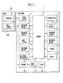
- FIG. 1 is a block diagram showing a configuration of an electronic apparatus according to the first embodiment of the present invention.
- the electronic device 1 according to the first embodiment includes an ID reading unit 2, a battery capacity storage unit 3, a battery remaining amount calculation unit 4, a battery remaining amount storage unit 5, and a capacity.
- Remaining amount adding unit 6 screen display unit 7, message sending unit 8, operation input unit 9, timing unit 10, self-power consumption storage unit 11, remaining battery level correction unit 12, control unit 13, ROM (Read Only Memory) 14, RAM (Random Access Memory) 15, a power supply unit 16, and a power switch 17.
- the electronic device 1 is configured so that the battery 20 can be mounted, and is driven by electric power supplied from the battery 20.
- the electronic device 1 includes a battery mounting part 200 for mounting the battery 20, and the battery 20 is mounted on the battery mounting part 200.
- the battery mounting part 200 has a terminal (not shown) connected to the terminal of the battery 20.
- the battery mounting part 200 may be anything that mounts at least one battery 20.
- a plurality of batteries 20 are selectively attached to the battery attachment part 200.
- the battery 20 includes an ID storage unit 21 that holds a battery ID unique to the battery, and a power supply unit 22 that supplies power to the electronic device 1.
- the battery ID preferably includes battery type information indicating the type of the battery. For example, if the battery ID starts with "1", the battery ID itself is 30 minutes, "2" is 60 minutes, "3" is 90 minutes, etc. Battery type information can be included.
- the electronic device 1 is a battery for which the battery ID from what number to what is 30 minutes, the battery ID from what number to what is a battery for 60 minutes, and the battery ID from what number to what number You may have the information that it is a battery for 90 minutes.
- the ID reading unit 2 reads the battery ID from the ID storage unit 21 of the battery 20 in use attached to the electronic device 1.
- the battery capacity storage unit 3 stores in advance the capacity of each of a plurality of types of batteries that can be used in the electronic device 1 in association with the battery type information.
- Battery remaining amount calculation unit 4 calculates the remaining amount of battery 20.
- the remaining amount can be calculated, for example, by measuring the terminal voltage of the battery 20. Specifically, it is possible to detect how much the remaining amount of the battery 20 is reduced by measuring the terminal voltage.
- the battery remaining amount calculation unit 4 can calculate the remaining amount with respect to the capacity of each of the plurality of types of batteries based on the battery capacity from the battery capacity storage unit 3 and the measured terminal voltage.
- Some batteries 20 supply the electronic device 1 with the capacity and remaining capacity of the battery as data.
- the battery capacity storage unit 3 can be deleted, and the battery remaining amount calculation unit 4 can determine the remaining amount of the battery 20 based on the remaining amount data supplied from the battery 20. May be calculated.
- the battery remaining amount storage unit 5 stores the remaining amount of the battery 20 calculated by the remaining battery amount calculating unit 4 in association with the remaining amount storage time that is the time when the battery ID and the remaining amount of the battery 20 are stored.
- the remaining battery level storage unit 5 has been mounted on the electronic device 1 (battery mounting unit 200). It is stored in association with the battery ID of the battery and the remaining amount storage time. Thus, it is preferable to store the remaining amount and the remaining storage time in association with each battery ID. Since the remaining amount of the battery decreases with the passage of time, the remaining amount of the stored battery can be corrected by storing the remaining amount storage time as will be described later. It is also possible to omit the function of correcting the remaining amount of the stored battery. In this case, the battery ID and the remaining amount may be stored in association with each other.
- the capacity remaining amount summing unit 6 is a capacity of a battery 20 that is in use and a capacity of a stored battery other than the battery 20 that is in use among stored batteries that are batteries whose remaining amount is stored in the battery remaining amount storage unit 5. And the total battery capacity that is the sum of the remaining amount of the battery 20 in use and the remaining amount of stored batteries other than the battery 20 in use is calculated.
- the screen display unit 7 displays a total capacity remaining amount display figure, an individual capacity remaining amount display figure, and various messages, which will be described later, indicating the battery capacity and the remaining amount.
- the message sending unit 8 sends various messages to the user to the screen display unit 7 to display them.
- the operation input unit 9 is a part for the user to input for operating the electronic device 1, and outputs an operation signal based on the user operation to the control unit 13.
- Time measuring unit 10 measures time.
- the timer 10 operates with power from a power source (not shown) such as a battery other than the battery 20 built in the electronic device 1 so that it can operate even when the battery 20 is removed.
- the self-power consumption storage unit 11 stores in advance the self-power consumption of each of a plurality of types of batteries that can be used in the electronic device 1 in association with the battery type information.
- the remaining battery level correction unit 12 is the difference between the remaining time of the stored battery and the current time, which is a battery whose remaining amount is stored in the battery remaining amount storage unit 5 in association with the battery ID and the remaining time.
- the remaining amount correction value is calculated based on the self power consumption per unit time obtained from the self power consumption storage unit 11, and the remaining amount of the stored battery is corrected by the remaining amount correction value.
- the control unit 13 controls the operation of the entire electronic device 1 by performing processing according to the program.
- the battery ID is read from the ID reading unit 2
- the capacity is read from the battery capacity storage unit 3
- the battery remaining amount calculation unit 4 is controlled
- the remaining battery level storage unit 5 such as the remaining amount is stored.
- Storage capacity remaining amount summing unit 6 control, screen display unit 7 display control, message sending unit 8 control, operation according to input from operation input unit 9, time information from time counting unit 10 Acquisition, reading of self-power consumption from the self-power consumption storage unit 11, control of the battery remaining amount correction unit 12, power ON / OFF control according to the power switch 17, reading of data in the ROM 14, various arithmetic processes, etc. Is mentioned.
- the control unit 13 includes first remaining amount information indicating the remaining amount of the battery 20 in use, and the remaining amount of a non-use battery other than the used battery whose remaining amount is stored in the remaining battery amount storage unit 5. It functions as a display control unit that controls to display the second remaining amount information indicating the above on the screen display unit 7.
- control unit 13 causes the battery remaining amount calculation unit 4 to calculate the remaining amount of the battery 20 that is in use among the stored batteries at a predetermined time T, and the used amount stored in the battery remaining amount storage unit 5 is used.
- the remaining amount of the battery 20 and the remaining amount storage time are updated, and functions as a remaining amount update control unit.
- control unit 13 attaches a new battery whose remaining amount is not stored in the battery remaining amount storage unit 5 to the electronic apparatus 1 and receives an instruction signal for storing the new battery remaining amount.
- the remaining amount of the new battery is stored in the remaining battery amount storage unit 5 in association with the battery ID and the remaining amount storage time of the battery, and functions as a remaining amount storage control unit.
- control unit 13 erases the remaining battery level, the battery ID corresponding to the remaining battery level, and the remaining storage time instructed by the user operation from the remaining battery level storage unit 5. It functions as a quantity erasure control unit.
- the ROM 14 stores a predetermined time T, a predetermined remaining amount Cmin, and a program for operating the control unit 13 described later.
- the RAM 15 is used as a work area for the control unit 13 during temporary data storage or calculation.
- the power supply unit 16 receives power from the power supply unit 22 of the battery 20 and supplies power to the electronic device 1 to drive it.
- the power switch 17 is a part where the user performs an input for operating the power ON / OFF of the electronic device 1, and instructs the power supply unit 16 to supply power in accordance with the user operation.
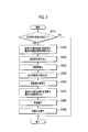
- step S ⁇ b> 10 of FIG. 2A the ID reading unit 2 reads the battery ID stored in the ID storage unit 21 of the battery 20 in use attached to the electronic device 1, and outputs this to the control unit 13.
- step S20 the control unit 13 reads out the battery IDs of all stored batteries whose remaining amount is stored in the remaining battery amount storage unit 5 in association with the battery ID and the remaining amount storage time.
- step S30 the control unit 13 performs a remaining amount correction process in order to correct the remaining amount of each stored battery stored in the remaining battery amount storage unit 5.
- the procedure of the remaining amount correction process will be described later.
- step S40 the control unit 13 reads the capacity CA of the battery 20 in use from the battery capacity storage unit 3 based on the battery type information included in the battery ID of the battery 20 in use.
- step S50 the control unit 13 determines whether or not the remaining amount of the battery 20 being used is stored in the remaining battery amount storage unit 5 based on the battery ID of the battery 20 being used. If stored (step S50: YES), the process proceeds to step S60. If not stored (step S50: NO), the process proceeds to step S90.
- step S60 the control unit 13 reads the capacities of all stored batteries except the battery 20 in use from the battery capacity storage unit 3, and causes the capacity remaining amount summing unit 6 to calculate the total CAmem of the read capacities.
- the control unit 13 causes the remaining capacity summing unit 6 to calculate the total battery capacity CAall obtained by adding CA and CAmem.
- step S80 the control unit 13 reads the remaining amount of all the stored batteries except the battery 20 in use from the remaining battery amount storage unit 5, and the total remaining amount CRmem is stored in the capacity remaining amount adding unit 6. To calculate. Thereafter, the process proceeds to step S220 in FIG. 2B.
- step S90 the control unit 13 determines the remaining amount CR of the battery 20 in use. Is calculated by the battery remaining amount calculation unit 4.
- step S100 the control unit 13 causes the capacity remaining amount summing unit 6 to calculate the total CAmem of the capacities of all stored batteries whose remaining amounts are stored in the battery remaining amount storage unit 5, and in step S110, The control unit 13 causes the remaining capacity summation unit 6 to calculate the total battery capacity CAall obtained by adding CA and CAmem.
- step S120 the control unit 13 reads the remaining amount of all stored batteries from the battery remaining amount storage unit 5, causes the total remaining amount CRmem to be calculated by the capacity remaining amount adding unit 6, and in step S130.
- the control unit 13 causes the capacity remaining amount summing unit 6 to calculate a total remaining battery level CRall obtained by adding up CRmem and the remaining amount CR of the battery 20 in use.
- step S140 the control unit 13 uses the capacity CA of the battery 20 in use, the remaining capacity CR of the battery 20 in use, the total battery capacity CAall, the total battery capacity CRall, and the like obtained above.
- the screen display unit 7 displays the remaining amount of the battery 20 in use, other stored batteries, and the total battery.
- the display form of the remaining amount displayed here is the same as the display form described in the remaining amount display process described later.
- step S150 of FIG. 2B the control unit 13 sends a message from the message sending unit 8 to the user to select whether or not to store the remaining amount of the currently used battery 20 in the remaining battery amount storage unit 5.
- the data is sent out and displayed on the screen display unit 7. A message display example will be described later.
- the reason for displaying the message will be explained.
- the user cannot know the status of the remaining amount of the battery until the battery is attached to the electronic device 1. It is possible that there is almost no remaining battery installed. Even if a battery with a small remaining amount is stored, it can be used only for a short time, so it may be preferable not to store the remaining amount of a battery with a small remaining amount. Therefore, an option of “do not memorize” is required.
- the remaining amount display performed in step S140 described above is intended to allow the user to recognize the current state of the remaining amount when determining whether or not the user stores the remaining amount of the battery.
- step S160 the control unit 13 determines whether or not the power switch 17 is pressed. If the power switch 17 is pressed (step S160: YES), the control unit 13 performs power-off processing in step S170. Do.
- step S180 the control unit 13 determines whether or not the remaining amount CR of the battery 20 currently in use is greater than or equal to a predetermined value Cmin stored in the ROM 14. Determine whether.
- step S180: YES If it is equal to or greater than the predetermined value Cmin (step S180: YES), the process proceeds to step S190. If it is smaller than the default value Cmin (step S180: NO), in step S170, the control unit 13 performs a power OFF process. This is because when the remaining amount CR of the battery 20 is smaller than the predetermined value Cmin, the electronic device 1 cannot be substantially operated, so that the operation of the electronic device 1 is automatically performed without pressing the power switch 17. This is to stop it.
- step S190 the control unit 13 determines whether an operation input for the message in step S150 has been performed on the operation input unit 9.
- step S190: YES the process proceeds to step S200.
- step S190: NO the process returns to step S160, and the subsequent processing is repeated.
- step S200 the control unit 13 determines whether or not “store” is selected based on the operation signal from the operation input unit 9. If “store” is selected (step S200: YES), the process proceeds to step S210. If “not store” is selected (step S200: NO), the process proceeds to step S220.
- step S210 the control unit 13 reads the current time from the time measuring unit 10, and associates the remaining amount CR, the battery ID, and the current time of the battery 20 in use as the remaining amount storage time, and the remaining battery amount storage unit. Write to 5.
- step S220 the control unit 13 performs a remaining amount display process.
- the remaining amount display processing procedure will be described later.
- the remaining amount storage unit 5 Since the battery has power consumption such as self-discharge and a protection circuit provided inside the battery, the remaining amount is consumed even if the circuit load is not connected. Therefore, when the battery remaining amount storage unit 5 stores the remaining amount and is not used for a long time, the remaining amount stored in the battery remaining amount storage unit 5 and the actual remaining amount are between. Will cause a difference.
- the process for correcting the difference in the remaining amount is a remaining amount correcting process described below.
- FIG. 3 is a flowchart showing the procedure of the remaining battery charge correction process.
- step S ⁇ b> 310 the control unit 13 determines whether there is a stored battery in which the remaining amount is stored in the remaining battery amount storage unit 5. When there is a stored battery (step S310: YES), the process proceeds to step S320, and when there is no stored battery (step S310: NO), the process ends.
- step S320 the control unit 13 reads the remaining storage time of each stored battery except the currently used battery 20 from the stored battery, from the remaining battery storage unit 5, and in step S330, the control unit 13 The current time is read from the time measuring unit 10.
- step S340 the control unit 13 calculates a time difference between the remaining amount storage time of each stored battery and the current time.
- step S350 the control unit 13 reads the self-power consumption per unit time of each stored battery from the self-power consumption storage unit 11 based on the battery type information included in the battery ID of each stored battery.
- step S360 the control unit 13 multiplies the self-power consumption per unit time read from the self-power consumption storage unit 11 by the time difference calculated in step S340, thereby calculating the remaining amount of each stored battery.
- the remaining battery charge correction unit 12 is controlled so as to calculate a remaining charge correction value for correction.
- step S370 the control unit 13 reads the remaining amount of the stored battery excluding the currently used battery 20 from the battery remaining amount storage unit 5, and in step S380, the control unit 13 determines the read remaining amount.
- the battery remaining amount correction unit 12 is controlled to perform correction using the remaining amount correction value calculated in step S360.
- step S390 the control unit 13 overwrites the remaining battery level after the correction of each stored battery calculated by the remaining battery level correction unit 12 on the remaining battery level storage unit 5, and also stores the remaining battery level. A process of changing the amount storage time to the time of correction is performed.
- step S220 the remaining amount display process in step S220 described above with reference to FIG. 2B will be described.
- FIG. 4 is a flowchart showing the remaining amount display processing procedure.
- the control unit 13 determines whether or not the power switch 17 is pressed. If the power switch 17 is pressed (step S410: YES), in step S420, the control unit 13 performs power-off processing. Do.
- step S430 the control unit 13 determines whether or not the predetermined time T in the ROM 14 has elapsed since the last remaining amount update. If the predetermined time T has elapsed (step S420: YES), the process proceeds to step S440. If the predetermined time T has not elapsed (step S420: NO), the process returns to step S410.
- step S440 the control unit 13 causes the battery remaining amount calculation unit 4 to calculate the remaining amount CR of the battery 20 currently in use.
- step S450 the control unit 13 determines whether or not the remaining amount CR of the battery 20 in use calculated in step S440 is equal to or greater than a predetermined value Cmin stored in the ROM 14. If the remaining amount CR is equal to or greater than the predetermined value Cmin (step S450: YES), the process proceeds to step S460. If the remaining amount CR is smaller than the predetermined value Cmin (step S450: NO), in step S420, the control unit 13 Perform OFF processing.
- step S460 the control unit 13 determines whether or not the remaining amount of the battery 20 in use is stored in the remaining battery amount storage unit 5. If stored (step S460: YES), the process proceeds to step S470. If not stored (step S460: NO), the process proceeds to step S480.
- step S470 the control unit 13 overwrites (updates) the remaining amount CR of the battery 20 in use in the remaining battery amount storage unit 5, and changes the remaining amount storage time to the time when the remaining amount is overwritten. Perform the process.
- the electric power of the electronic device 1 is supplied from a battery attached to the electronic device 1, no electric power is supplied to the electronic device 1 when the battery is removed.
- the remaining battery level is stored in the remaining battery level storage unit 5, this remaining level needs to be updated when the battery is removed.
- step S480 the control unit 13 causes the capacity remaining amount summing unit 6 to calculate the total remaining battery amount CRall obtained by adding up the remaining amount CR of the battery 20 in use and the previously calculated CRmem.
- step S490 the control unit 13 uses the capacity CA of the battery 20 in use, the remaining capacity CR of the battery 20 in use, the total battery capacity CAall obtained previously, the total battery capacity CRall, etc.
- the screen display unit 7 displays the remaining amount of the battery 20 in use, other stored batteries, and the total battery. Thereafter, the process returns to step S430, and the subsequent processing is repeated.
- FIG. 5 is a diagram showing an example of the remaining amount display screen in the first embodiment, showing a case where the remaining amount of three batteries is displayed
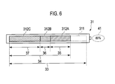
- FIG. 6 is a total capacity remaining amount display graphic in FIG.
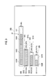
- FIG. 7 is a diagram showing the individual capacity remaining amount display graphic in FIG.
- the remaining capacity display screen 30 displays the total capacity remaining display graphic 31 indicating the total battery capacity and the total battery remaining capacity of the three batteries, and the capacity and remaining capacity of each battery individually.
- the individual capacity remaining amount display figures 32A to 32C correspond to the batteries A to C, and the capacity of each battery is in the relationship of the capacity of the battery C> the capacity of the battery A> the capacity of the battery B.
- the ratio of the remaining capacity to the capacity is 80% for battery A, 50% for battery B, and 100% for battery C.
- FIG. 5 is an example of a remaining amount display screen when the remaining amount is displayed according to the order in which the remaining amount is initially stored in the battery remaining amount storage unit 5, and the remaining amount in the order of battery A ⁇ battery B ⁇ battery C. Is a display example when the battery A is used.
- the total capacity remaining amount display graphic 31 includes a total capacity display portion 311 indicating the total capacity of the batteries A to C and a remaining amount display portion 312A to 312C indicating the remaining amount of the batteries A to C. Is displayed.
- the remaining amount display portions 312A to 312C are displayed connected in series, and constitute a total remaining amount display portion indicating the total remaining amount of the batteries A to C.
- capacity display portions 321A to 321C indicating the capacities of the corresponding batteries A to C and remaining amount display portions 322A to 322C indicating the remaining amount are displayed, respectively.
- the total capacity remaining display graphic 31 and the individual capacity remaining display graphics 32A to 32C are displayed in sizes corresponding to the respective capacities, and the length 33 of the total capacity display portion 311 of the total capacity remaining display graphic 31 is displayed. Is displayed to be the sum of the lengths of the capacity display portions 321A to 321C of the individual capacity remaining amount display figures 32A to 32C. The lengths of the capacity display portions 321A to 321C of the individual capacity remaining amount display figures 32A to 32C are displayed in a length corresponding to the capacity of the batteries A to C.
- the remaining amount display portions 312A to 312C are displayed in sizes corresponding to the respective remaining amounts, and the lengths 35 to 37 of the remaining amount display portions 312A to 312C correspond to the remaining amount of the batteries A to C. It is displayed with the corresponding length. Further, the lengths of the remaining capacity display portions 322A to 322C of the individual capacity remaining amount display graphics 32A to 32C are the same as the lengths 35 to 37 of the remaining capacity display portions 312A to 312C of the total capacity remaining amount display graphic 31. Is displayed.
- the ratio between the total capacity display portion 311 length 33 in the total capacity remaining amount display graphic 31 and the total length 34 of the remaining capacity display portions 312A to 312C is equal to the total battery capacity of the three batteries and the total battery remaining amount. Displayed to be the same as the ratio to the quantity.
- the ratio between the length 38 of the capacity display portion 321A and the length 39 of the remaining amount display portion 322A is the same as the ratio between the capacity and the remaining amount of the battery A. Is displayed. The same applies to the individual capacity remaining amount display figures 32B and 32C.
- the remaining capacity display portions 312A to 312C in the total capacity remaining amount display graphic 31 and the remaining capacity display portions 322A to 322C in the individual capacity remaining amount display graphics 32A to 32C are displayed in corresponding forms, and the user has a corresponding relationship. It can be visually recognized.
- the remaining amount display portions 312A and 322A of the battery A in use and the remaining amount display portions 312B, 322B, 312C and 322C of the other batteries B and C are displayed in a form that can be distinguished.
- the remaining amount display portions 312A and 322A are displayed with diagonal lines indicating the remaining amount of the battery in use, and can be distinguished from the remaining amount display portions 312B, 322B, 312C, and 322C at a glance. .
- the individual capacity remaining amount display graphics 32A to 32C are displayed from the top of the individual capacity remaining amount display graphics 32A, 32B, and 32C in accordance with the order in which the remaining amounts of the corresponding batteries A to C are first stored in the battery remaining amount storage unit 5. Arranged in order.
- the remaining amount display portion 312A corresponding to the battery A in use is the right end side in the figure, and among the remaining amount display portions 312B and 312C corresponding to the unused batteries B and C, The remaining amount display portions 312A to 312C are arranged in series so that the remaining amount display portion 312B of the battery B in the order of storing the remaining amount is positioned close to the remaining amount display portion 312A of the battery A.
- the remaining amount display portion 312A is reduced from the right end of the remaining amount display portion 312A to the left so that the user can easily recognize the decrease in the remaining amount. Is displayed.
- the remaining capacity ratio display section 41 provided adjacent to the total capacity remaining display graphic 31 displays the ratio of the total remaining battery capacity to the total battery capacity of the three batteries (80% in the illustrated example).
- the remaining capacity ratio display units 42 and 43 provided adjacent to the individual capacity remaining amount display graphic 32A, the ratio of the remaining capacity with respect to the capacity of the battery A (80% in the illustrated example of FIG. 7), the battery with respect to the total remaining battery capacity.
- the remaining amount of A (33.3% in the illustrated example of FIG. 7) is displayed.
- the battery ID display unit 44 displays the battery ID of the battery A. Similar contents are also displayed on the individual capacity remaining amount display figures 32B and 32C.
- FIG. 8 is a diagram illustrating another example of the remaining amount display screen according to the first embodiment. 8 that are the same as those in FIG. 5 are given the same reference numerals, and redundant descriptions are omitted.
- the remaining amount display screen 30 ⁇ / b> A shown in FIG. 8 is displayed when the remaining amount is displayed in the order stored in the battery remaining amount storage unit 5.
- An example of the screen is different from the remaining amount display screen 30 in FIG. 5 in that the battery in use is the battery C.
- the remaining amount display portions 312C and 322C of the battery C are displayed with diagonal lines indicating that the remaining amount of the battery in use, and at a glance with the remaining amount display portions 312B, 322B, 312C, and 322C of the batteries A and B. It is a form that can be distinguished by.
- the remaining amount display portion 312C corresponding to the battery C being used is the right end in the figure, and the remaining amount display portion corresponding to the batteries A and B that are not used.
- the remaining amount display portions 312A to 312C are serially arranged so that the remaining amount display portion 312A of the battery A in the order in which the remaining amount is stored is closer to the remaining amount display portion 312C of the battery C. Be placed.
- the remaining amount of the battery in use is displayed on the right end side regardless of the storage order, so that the user can easily recognize the decrease in the remaining amount.
- FIG. 9 is a diagram showing still another example of the remaining amount display screen in the first embodiment. Note that, in FIG. 9, the same reference numerals are given to portions that overlap with FIG. 5, and overlapping descriptions are omitted.
- FIG. 9 is an example of the remaining amount display screen when the battery A is used and the display is performed in the order of the remaining amount.
- the individual capacity remaining amount display figures 32A to 32C The display figures 32C, 32A, and 32B are arranged in this order.
- the remaining amount display portion 312A corresponding to the battery A being used is the right end side in the drawing, and corresponds to the batteries B and C that are not used.
- the remaining amount display portions 312B and 312C are serially arranged so that the remaining amount display portion 312C of the battery C having a large remaining amount is positioned close to the remaining amount display portion 312A of the battery A. Be placed.
- Such a remaining amount display screen 30B makes it easier for the user to grasp the remaining amount of each battery.
- both the total capacity remaining amount display graphic 31 and the individual capacity remaining amount display graphics 32A to 32C are displayed simultaneously. Only the display graphic 31 or only the individual capacity remaining amount display graphic 32A to 32C may be used. Of course, it is preferable to display both.
- the total capacity remaining amount display figure 31 and the individual capacity remaining amount display figures 32A to 32C may be selectively displayed. Furthermore, it is preferable to display a figure, but it may be only a numeric character string that directly represents a capacity such as 50% or 80%.
- First remaining amount information indicating the remaining amount of the battery 20 in use, and second indicating the remaining amount of a battery other than the used battery whose remaining amount is stored in the remaining battery amount storage unit 5 Any device that displays remaining amount information may be used.
- FIG. 10 is a diagram showing an example of a remaining amount display screen that displays a message for allowing the user to select whether or not to store the remaining amount of the battery currently in use in the remaining battery amount storage unit 5.
- the same reference numerals are given to the portions overlapping with those in FIG. 5, and the overlapping description is omitted.
- step S150 of FIG. 2B described above when the remaining battery level is low, an option of not storing the remaining battery level is required. Therefore, it is necessary to display on the screen display unit 7 a message for allowing the user to select whether or not to store the remaining battery level in use in the remaining battery level storage unit 5.
- the remaining amount display screen 30C shown in FIG. 10 is for allowing the user to select whether or not to store the remaining amount of the battery in use in the remaining battery amount storage unit 5 with respect to the remaining amount display screen 30A shown in FIG.
- the message box 50 is added and displayed.
- a “store” button 51 for instructing storage and a “not store” button 52 for instructing not to store are displayed.
- the user operates the operation input unit 9 to select a selection frame 53 for selecting a battery for storing the remaining amount and a selection frame 54 for selecting the “store” button 51 or the “do not store” button 52.
- a selection frame 53 for selecting a battery for storing the remaining amount
- a selection frame 54 for selecting the “store” button 51 or the “do not store” button 52.
- the user determines the number of batteries to be carried in accordance with the usage status of the electronic device 1, and in this case, it is necessary to delete from the screen display unit 7 the remaining battery amount display that cannot be carried. The same applies to the remaining amount display of the battery that has already run out.
- FIG. 11 is a diagram showing an example of a remaining amount display screen displaying a message for deleting the remaining amount stored in the battery remaining amount storage unit 5.
- the same reference numerals are given to the portions overlapping with those in FIG. 5, and the overlapping description is omitted.
- the remaining amount display screen 30D shown in FIG. 11 is for allowing the user to select whether or not to delete the selected remaining battery amount from the remaining battery amount storage unit 5 with respect to the remaining amount display screen 30 shown in FIG.
- the message box 55 is added and displayed.
- an “erase” button 56 for instructing to erase and an “not erase” button 57 for instructing not to erase are displayed.
- the user operates the operation input unit 9 to select a selection frame 58 for selecting a battery whose remaining amount is to be deleted, and a selection frame 59 for selecting a “delete” button 56 or a “do not delete” button 57. It moves to a desired position on the remaining amount display screen 30D and performs an operation for determination.
- the control unit 13 displays the remaining battery level, the battery ID, and the remaining storage time of the selected battery. And the screen display unit 7 is controlled to delete the remaining capacity display portion and the individual capacity remaining display graphic in the total capacity remaining display graphic 31 corresponding to the selected battery from the remaining capacity display screen 30D. .
- each battery ID is displayed on the screen display unit 7 in correspondence with the individual capacity remaining amount display graphic of each battery.
- the user can select the battery to be used next based on the displayed remaining amount and the battery ID. In this case, it is necessary to display the battery ID on the battery itself.
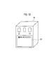
- FIG. 12 is a diagram showing a display example of the battery ID in the battery. As shown in FIG. 12, a label 23 on which a battery ID is printed is provided on the surface of the battery 20. In the label 23, the battery ID is displayed in the same form as the battery ID displayed on the screen display unit 7 in association with the individual capacity remaining amount display graphic.
- the remaining amount of the battery used in the electronic device 1 in the remaining battery amount storage unit 5, in addition to the remaining amount of the battery currently in use.
- the remaining amount of batteries not in use can be added together and displayed on the screen display unit 7, and the user can easily grasp the total remaining amount of all the batteries.
- FIGS. 5 to 11 the remaining capacity display portion of the battery in use is indicated by hatching as a method of distinguishing from the battery not in use, but the present invention is not limited to this, and the color, pattern, gloss, texture You may distinguish by changing etc.
- the total capacity remaining amount display graphic 31 and the individual capacity remaining amount display graphic 32A to 32C are not limited to the display positional relationships shown in FIGS. 5 and 8 to 11.
- FIG. 9 shows an example in which the individual capacity remaining amount display figures 32A to 32C are arranged from the top in the descending order of the remaining amount.
- FIG. 13 is a block diagram showing a configuration of an electronic apparatus according to the second embodiment of the present invention.
- symbol is attached
- the electronic device 1A according to the second embodiment is different from the electronic device 1 according to the first embodiment illustrated in FIG. It is the structure which added the part 19.
- FIG. 13 is the structure which added the part 19.
- the average power consumption calculation unit 18 calculates the average power consumption of the electronic device 1A from the decrease value per unit time of the remaining amount calculated by the battery remaining amount calculation unit 4.
- the average power consumption calculation unit 18 may be configured to calculate the average power consumption from the power per unit time supplied from the power supply unit 22 of the battery 20 to the electronic device 1A.
- the average power consumption storage unit 19 stores the average power consumption of the electronic device 1A calculated by the average power consumption calculation unit 18.
- the control unit 13 calculates the operable time based on the remaining amount of each battery and the total remaining battery amount from the remaining amount of each battery, the total remaining battery amount, and the average consumed power stored in the average consumed power storage unit 19, respectively. It functions as an operable time calculation unit. In addition, the control unit 13 causes the screen display unit 7 to display a total time display graphic, an individual time display graphic, etc., which will be described later, indicating the operable time of the electronic device 1A based on the remaining battery level.
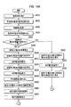
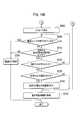
- 14A and 14B are flowcharts showing the operation of the electronic device 1A. 14A and 14B, the processes in steps S510 to S630 and S680 to S740 are the same as steps S10 to S220 in the flowcharts of FIGS. 2A and 2B described in the first embodiment, and thus detailed description thereof is omitted. Steps S640 to S670 and S750 that are different from the first embodiment will be mainly described.
- step S640 the control unit 13 reads out the average power consumption of the electronic device 1A that is calculated in advance by the average power consumption calculation unit 18 and stored in the average power consumption storage unit 19.
- step S650 the control unit 13 operates based on the average power consumption of the electronic device 1A and the remaining amount CR of the battery 20 in use calculated in step S590. Is calculated.
- step S660 the control unit 13 calculates the total operable time based on the total battery remaining amount CRall based on the average power consumption of the electronic device 1A and the total battery remaining amount CRall calculated in step S630. Further, the control unit 13 calculates the operable time based on the remaining amount of each stored battery, based on the remaining amount of each stored battery stored in the remaining battery amount storage unit 5 and the average power consumption of the electronic device 1A. .
- step S670 the controller 13 determines the operable time based on the remaining amount CR of the battery 20 in use determined above, the total operable time based on the total remaining battery amount CRall, and the remaining amount of each stored battery.
- the screen display unit 7 is caused to display the operable time based on the remaining battery 20 in use, other stored batteries, and the total remaining battery.
- the display form of the operable time displayed here is the same as the display form described in the operable time display process described later.
- step S750 of FIG. 14B the control unit 13 performs an operable time display process.
- the procedure of the operable time display process in step S750 will be described with reference to the flowchart shown in FIG.
- steps S810 to S880 are the same as that of steps S10 to S480 of the flowchart of FIG. 4 described in the first embodiment, and thus detailed description thereof is omitted, and the process of the first embodiment is omitted.
- Steps S890 to S920 which are different points will be mainly described.
- step S890 the control unit 13 reads out the average power consumption of the electronic device 1A stored in the average power consumption storage unit 19.
- step S900 the control unit 13 operates based on the average power consumption of the electronic device 1A and the remaining amount CR of the battery 20 in use calculated in step S840, and the operable time by the remaining amount CR of the battery 20 in use. Is calculated.
- step S910 the control unit 13 calculates the total operable time based on the total battery remaining amount CRall based on the average power consumption of the electronic device 1A and the total battery remaining amount CRall calculated in step S880.
- step S920 the control unit 13 uses the battery 20 in use using the remaining operation time by the remaining battery CR, the total operation time by the total battery remaining CRall, and the like. Then, the screen display unit 7 is made to display the operable time based on the remaining stored battery and the remaining battery amount. Thereafter, the process returns to step S830, and the subsequent processing is repeated.
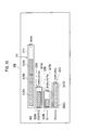
- FIG. 16 is a diagram showing an example of the operable time display screen in the second embodiment
- FIG. 17 is a diagram showing the total time display graphic in FIG. 16
- FIG. 18 is an individual time display graphic in FIG. FIG. 16 to FIG. 18, the same reference numerals are given to the same parts as those in FIG. 5 to FIG.
- the operable time display screen 30E shown in FIG. 16 replaces the remaining amount of FIG. 5 with the operable time of the electronic device 1A based on the remaining amount, and the remaining operable time is left in the battery remaining amount storage unit 5. It is an example of the operation possible time display screen at the time of making it display according to the order which memorize
- the remaining amount is stored in the order of battery A ⁇ battery B ⁇ battery C, and battery A is used.
- the operable time is 1 hour (1h00m) depending on the remaining amount of battery A in use.
- a display example is shown in a case where the operable time based on the remaining amount of battery is 30 minutes (0h30m) and the operable time based on the remaining amount of the battery C is 1 hour 30 minutes (1h30m).
- the operable time display screen 30E replaces the remaining capacity display screen 30 shown in FIG. 5 with a total capacity remaining display graphic 31 replaced with a total time display graphic 31t, and an individual capacity remaining display graphic.
- 32A to 32C are replaced with individual time display graphics 32At to 32Ct.
- the total time display graphic 31t is an operation time of the electronic device 1A based on the total battery capacity of the three batteries (operation time of the electronic device 1A when all three batteries are fully charged) and an electronic device based on the total remaining battery level. 1A shows the operable time.
- the individual time display graphics 32At to 32Ct indicate the operation time of the electronic device 1A according to the capacity of each battery (operation time of the electronic device 1A when each battery is fully charged) and the operation of the electronic device 1A according to the remaining amount. Show possible time individually.
- the operable time display screen 30E is different from the remaining amount display screen 30 shown in FIG. 5 in that the total capacity display portion 311 is the total time display portion 311t and the remaining amount display portions 312A to 312C are the remaining time display portions 312At. 312Ct, capacity display portions 321A to 321C are replaced with individual time display portions 321At to 321Ct, and remaining amount display portions 322A to 322C are replaced with remaining time display portions 322At to 322Ct, respectively.
- the total time display portion 311t indicates the total operable time of the electronic device 1A according to the capacity of the batteries A to C (the operable time of the electronic device 1A when the batteries A to C are fully charged), and the remaining time is displayed.
- the portions 312At to 312Ct indicate the operable time of the electronic apparatus 1A depending on the remaining amount of the batteries A to C of the corresponding batteries A to C.
- the remaining time display portions 312At to 312Ct are connected and displayed in series, and constitute a total remaining time display portion indicating the total operable time depending on the remaining amount of the batteries A to C.
- the individual time display portions 321At to 321Ct are the operable time of the electronic device 1A with the capacity of the corresponding batteries A to C (the operable time of the electronic device 1A with the individual batteries when the batteries A to C are all fully charged)
- the remaining time display portions 322At to 322Ct indicate the operable time of the electronic device 1A depending on the remaining amount of the corresponding batteries A to C.
- the operable time display unit 61 provided adjacent to the total time display graphic 31t displays the operable time (3 hours in the illustrated example) based on the total remaining battery capacity of the three batteries. .
- the operable time display section 62 provided adjacent to the individual time display graphic 32At displays the operable time based on the remaining amount of the battery A (1 hour in the illustrated example of FIG. 18).
- the operable time ratio display unit 63 displays the ratio of the operable time based on the remaining amount of the battery A to the operable time based on the total remaining battery amount (33.3% in the illustrated example of FIG. 18).
- the same contents are displayed for the individual time display figures 32Bt and 32Ct.
- the state of the remaining battery level can be recognized by the user as information on the operable time. .
- FIG. 16 shows an example in which the individual time display graphics 32At to 32Ct are sequentially arranged from the top in the storage order of the remaining amount, but the remaining amount (length of operable time) is the same as in the first embodiment. You may arrange and display according to the order of size.
- the total time display graphic 31t and the individual time display graphic 32At to 32Ct are displayed at the same time. However, only the total time display graphic 31t may be displayed. Only the individual time display figures 32At to 32Ct may be provided. Of course, it is preferable to display both.
- the total time display graphic 31t and the individual time display graphic 32At to 32Ct may be selectively displayed. Furthermore, it is preferable to display a figure, but it may be only a numeric character string that directly represents an operable time (remaining time) such as 1h00m and 0h30m.
- First operable time information indicating operable time according to the remaining amount of the battery 20 in use, and a non-used battery other than the currently used battery whose remaining amount is stored in the remaining battery amount storage unit 5 Any other device may be used as long as it can display the second operable time information indicating the operable time according to the remaining amount.
- the present invention can be applied to portable electronic devices such as video cameras, digital cameras, notebook PCs, mobile phones, and any other electronic devices driven by batteries.
Landscapes
- Physics & Mathematics (AREA)
- General Physics & Mathematics (AREA)
- Secondary Cells (AREA)
- Charge And Discharge Circuits For Batteries Or The Like (AREA)
- Tests Of Electric Status Of Batteries (AREA)
- Power Sources (AREA)
Abstract
Description
図1は、本発明の第1の実施の形態に係る電子機器の構成を示すブロック図である。図1に示すように、第1の実施の形態に係る電子機器1は、ID読み取り部2と、電池容量記憶部3と、電池残量算出部4と、電池残量記憶部5と、容量残量合算部6と、画面表示部7と、メッセージ送出部8と、操作入力部9と、計時部10と、自己消費電力記憶部11と、電池残量補正部12と、制御部13と、ROM(Read Only Memory)14と、RAM(Random Access Memory)15と、電源部16と、電源スイッチ17とを備える。
図13は、本発明の第2の実施の形態に係る電子機器の構成を示すブロック図である。なお、図13に示す第2の実施の形態の構成要素において、第1の実施の形態と同様の構成要素については同一の符号を付し、詳細な説明は省略する。
Claims (58)
- 電池からの電力によって動作する電子機器において、
前記電子機器に装着された使用中の電池から電池IDを読み取るID読み取り部と、
前記使用中の電池の残量を算出する電池残量算出部と、
前記電子機器に選択的に装着した複数の電池の残量を、それぞれの電池IDと対応付けて記憶する電池残量記憶部と、
画面表示部と、
前記使用中の電池の残量を示す第1の残量情報と、前記電池残量記憶部に残量を記憶させた前記使用中の電池以外の非使用中の電池の残量を示す第2の残量情報とを前記画面表示部に表示するよう制御する表示制御部と
を備えることを特徴とする電子機器。 - 電池からの電力によって動作する電子機器において、
前記電子機器に装着された使用中の電池から電池IDを読み取るID読み取り部と、
前記使用中の電池の残量を算出する電池残量算出部と、
前記電子機器に選択的に装着した複数の電池の残量を、それぞれの電池IDと対応付けて記憶する電池残量記憶部と、
前記複数の電池それぞれの残量に基づいて、前記複数の電池それぞれによって前記電子機器が動作可能な動作可能時間を算出する動作可能時間算出部と、
画面表示部と、
前記使用中の電池による動作可能時間を示す第1の動作可能時間情報と、前記電池残量記憶部に残量を記憶させた前記使用中の電池以外の非使用中の電池による動作可能時間を示す第2の動作可能時間情報とを前記画面表示部に表示するよう制御する表示制御部と
を備えることを特徴とする電子機器。 - 前記電子機器で使用可能な複数種類の電池の容量を電池の種類情報と対応付けて記憶する電池容量記憶部をさらに備え、
前記電池残量算出部は、前記電池容量記憶部に記憶された電池の容量を用いて電池の残量を算出することを特徴とする請求項1または2に記載の電子機器。 - 前記電池残量記憶部は、前記複数の電池の電池IDと対応付けて前記複数の電池それぞれの残量を記憶した残量記憶時刻を記憶することを特徴とする請求項1乃至3のいずれか1項に記載の電子機器。
- 前記使用中の電池の残量を既定時間ごとに前記電池残量算出部に算出させ、前記電池残量記憶部に記憶された前記使用中の電池の残量を、前記既定時間ごとに前記電池残量算出部で算出された値に更新するとともに、前記電池残量記憶部に記憶された前記使用中の電池の前記残量記憶時刻を、残量を更新した時刻に変更する残量更新制御部をさらに備えることを特徴とする請求項4に記載の電子機器。
- 前記電子機器で使用可能な複数種類の電池の単位時間あたりの自己消費電力を電池の種類情報と対応付けて記憶する自己消費電力記憶部と、
前記電池残量記憶部に記憶された前記残量記憶時刻と現在時刻との差および前記単位時間あたりの自己消費電力に基づいて残量補正値を算出し、前記電池残量記憶部に記憶された電池の残量を前記残量補正値により補正する電池残量補正部と
をさらに備えることを特徴とする請求項4または5に記載の電子機器。 - 前記電池残量記憶部に記憶されていない新たな電池が前記電子機器に装着された場合に、前記新たな電池の残量を前記電池残量記憶部に記憶させるか否かをユーザに選択させるためのメッセージを前記画面表示部に表示させるメッセージ送出部と、
前記新たな電池の残量を記憶する指示信号が入力された場合に、前記電池残量算出部により算出された前記新たな電池の残量を、前記新たな電池のIDと対応付けて前記電池残量記憶部に記憶させる残量記憶制御部と
をさらに備えることを特徴とする請求項1乃至6のいずれか1項に記載の電子機器。 - 前記電池残量記憶部に残量が記憶された電池から選択される1つの電池の残量を消去する指示信号が入力された場合に、前記電池残量記憶部から、前記指示信号により指示された電池の電池IDと残量とを消去する残量消去制御部をさらに備えることを特徴とする請求項1乃至7のいずれか1項に記載の電子機器。
- 前記表示制御部は、前記第1の残量情報として前記使用中の電池の残量を示す第1の表示図形と、前記第2の残量情報として前記非使用中の電池の残量を示す第2の表示図形とを個別に前記画面表示部に表示するよう制御することを特徴とする請求項1に記載の電子機器。
- 前記表示制御部は、前記第1および第2の表示図形に対応してそれぞれの電池の電池IDを前記画面表示部に表示するよう制御することを特徴とする請求項9に記載の電子機器。
- 前記第1の表示図形は、前記使用中の電池の容量を示す容量表示部分と前記使用中の電池の残量を示す残量表示部分とを含み、
前記第2の表示図形は、前記非使用中の電池の容量を示す容量表示部分と前記非使用中の電池の残量を示す残量表示部分とを含み、
前記表示制御部は、前記第1および第2の表示図形における前記容量表示部分および残量表示部分を、それぞれの容量および残量に応じた大きさで表示するよう制御することを特徴とする請求項9または10に記載の電子機器。 - 前記表示制御部は、前記第1および第2の表示図形に対応して、前記容量表示部分に対する前記残量表示部分の比率を前記画面表示部に表示するよう制御することを特徴とする請求項11に記載の電子機器。
- 前記表示制御部は、前記第1の動作可能時間情報として前記使用中の電池による動作可能時間を示す数字および文字を含む第1の数字文字列と、前記第2の動作可能時間情報として前記非使用中の電池による動作可能時間を示す数字および文字を含む第2の数字文字列とを個別に前記画面表示部に表示するよう制御することを特徴とする請求項2に記載の電子機器。
- 前記表示制御部は、前記第1および第2の数字文字列に対応してそれぞれの電池の電池IDを前記画面表示部に表示するよう制御することを特徴とする請求項13に記載の電子機器。
- 前記表示制御部は、前記第1の動作可能時間情報として前記使用中の電池による動作可能時間を示す第1の表示図形と、前記第2の動作可能時間情報として前記非使用中の電池による動作可能時間を示す第2の表示図形とを個別に前記画面表示部に表示するよう制御することを特徴とする請求項2に記載の電子機器。
- 前記表示制御部は、前記第1および第2の表示図形に対応してそれぞれの電池の電池IDを前記画面表示部に表示するよう制御することを特徴とする請求項15に記載の電子機器。
- 前記第1の表示図形は、前記使用中の電池の容量に基づく動作可能時間を示す第1の表示部分と前記使用中の電池の残量に基づく動作可能時間を示す第2の表示部分とを含み、
前記第2の表示図形は、前記非使用中の電池の容量に基づく動作可能時間を示す第1の表示部分と前記非使用中の電池の残量に基づく動作可能時間を示す第2の表示部分とを含み、
前記表示制御部は、前記第1および第2の表示図形における前記第1および第2の表示部分を、それぞれの動作可能時間に応じた大きさで表示するよう制御することを特徴とする請求項15または16に記載の電子機器。 - 前記表示制御部は、前記第1および第2の表示図形に対応して、前記第1の表示部分に対する前記第2の表示部分の比率を前記画面表示部に表示するよう制御することを特徴とする請求項17に記載の電子機器。
- 前記使用中の電池の容量と前記非使用中の電池の容量との合計である合計電池容量を算出するとともに、前記使用中の電池の残量と前記非使用中の電池の残量との合計である合計電池残量を算出する容量残量合算部をさらに備え、
前記表示制御部は、前記合計電池容量を示す合計容量表示部分と前記合計電池残量を示す合計残量表示部分とを含む合計容量残量表示図形を前記画面表示部に表示するよう制御することを特徴とする請求項1に記載の電子機器。 - 前記合計容量残量表示図形における前記合計残量表示部分は、前記第1の残量情報を示す残量表示部分と前記第2の残量情報を示す残量表示部分とを連結したものであることを特徴とする請求項19に記載の電子機器。
- 前記表示制御部は、前記第1の残量情報を示す残量表示部分と前記第2の残量情報を示す残量表示部分を、それぞれの残量に応じた大きさで表示するよう制御することを特徴とする請求項19または20に記載の電子機器。
- 前記表示制御部は、前記合計容量表示部分に対する前記合計残量表示部分の比率を前記画面表示部に表示するよう制御することを特徴とする請求項19乃至21のいずれか1項に記載の電子機器。
- 前記使用中の電池の容量と前記非使用中の電池の容量との合計である合計電池容量を算出するとともに、前記使用中の電池の残量と前記非使用中の電池の残量との合計である合計電池残量を算出する容量残量合算部をさらに備え、
前記表示制御部は、前記電子機器が前記合計電池残量により動作可能な動作可能時間を示す数字および文字を含む数字文字列を前記画面表示部に表示するよう制御することを特徴とする請求項2に記載の電子機器。 - 前記使用中の電池の容量と前記非使用中の電池の容量との合計である合計電池容量を算出するとともに、前記使用中の電池の残量と前記非使用中の電池の残量との合計である合計電池残量を算出する容量残量合算部をさらに備え、
前記表示制御部は、前記電子機器が前記合計電池容量により動作可能な動作可能時間を示す合計時間表示部分と前記電子機器が前記合計電池残量により動作可能な動作可能時間を示す合計残り時間表示部分とを含む時間表示図形を前記画面表示部に表示するよう制御することを特徴とする請求項2に記載の電子機器。 - 前記合計残り時間表示部分は、前記第1の動作可能時間情報を示す残り時間表示部分と前記第2の動作可能時間情報を示す残り時間表示部分とを連結したものであることを特徴とする請求項24に記載の電子機器。
- 前記表示制御部は、前記第1の動作可能時間情報を示す残り時間表示部分と前記第2の動作可能時間情報を示す残り時間表示部分を、それぞれの残り時間に応じた大きさで表示するよう制御することを特徴とする請求項25に記載の電子機器。
- 電子機器に装着された使用中の電池から電池IDを読み取り、
前記使用中の電池の残量を算出し、
前記電子機器に選択的に装着した複数の電池の残量を、それぞれの電池IDと対応付けて電池残量記憶部に記憶し、
前記使用中の電池の残量を示す第1の残量情報と、前記電池残量記憶部に残量を記憶させた前記使用中の電池以外の非使用中の電池の残量を示す第2の残量情報とを画面表示部に表示する
ことを特徴とする電池残量表示方法。 - 電子機器に装着された使用中の電池から電池IDを読み取り、
前記使用中の電池の残量を算出し、
前記電子機器に選択的に装着した複数の電池の残量を、それぞれの電池IDと対応付けて電池残量記憶部に記憶し、
前記複数の電池それぞれの残量に基づいて、前記複数の電池それぞれによって前記電子機器が動作可能な動作可能時間を算出し、
前記使用中の電池による動作可能時間を示す第1の動作可能時間情報と、前記電池残量記憶部に残量を記憶させた前記使用中の電池以外の非使用中の電池による動作可能時間を示す第2の動作可能時間情報とを画面表示部に表示する
ことを特徴とする動作可能時間表示方法。 - 前記電子機器で使用可能な複数種類の電池の容量を電池の種類情報と対応付けて記憶する電池容量記憶部から電池の容量を読み出し、
前記電池の残量を前記電池容量記憶部より読み出した電池の容量を用いて算出することを特徴とする請求項27に記載の電池残量表示方法。 - 前記電子機器で使用可能な複数種類の電池の容量を電池の種類情報と対応付けて記憶する電池容量記憶部から電池の容量を読み出し、
前記電池による動作可能時間を前記電池容量記憶部より読み出した電池の容量を用いて算出することを特徴とする請求項28に記載の動作可能時間表示方法。 - 前記複数の電池の電池IDと対応付けて前記複数の電池それぞれの残量を記憶した残量記憶時刻を前記電池残量記憶部に記憶することを特徴とする請求項27または29に記載の電池残量表示方法。
- 前記複数の電池の電池IDと対応付けて前記複数の電池それぞれの残量を記憶した残量記憶時刻を前記電池残量記憶部に記憶することを特徴とする請求項28または30に記載の動作可能時間表示方法。
- 前記使用中の電池の残量を既定時間ごとに算出し、前記電池残量記憶部に記憶された前記使用中の電池の残量を算出した残量に更新するとともに、前記電池残量記憶部に記憶された前記使用中の電池の前記残量記憶時刻を、残量を更新した時刻に変更することを特徴とする請求項31に記載の電池残量表示方法。
- 前記使用中の電池の残量を既定時間ごとに算出し、前記電池残量記憶部に記憶された前記使用中の電池の残量を算出した残量に更新するとともに、前記電池残量記憶部に記憶された前記使用中の電池の前記残量記憶時刻を、残量を更新した時刻に変更することを特徴とする請求項32に記載の動作可能時間表示方法。
- 前記電子機器で使用可能な複数種類の電池の単位時間あたりの自己消費電力を電池の種類情報と対応付けて記憶する自己消費電力記憶部から自己消費電力を読み出し、
前記電池残量記憶部に記憶された前記残量記憶時刻と現在時刻との差および前記単位時間あたりの自己消費電力に基づいて残量補正値を算出し、前記電池残量記憶部に記憶された電池の残量を前記残量補正値により補正することを特徴とする請求項31または33に記載の電池残量表示方法。 - 前記電子機器で使用可能な複数種類の電池の単位時間あたりの自己消費電力を電池の種類情報と対応付けて記憶する自己消費電力記憶部から自己消費電力を読み出し、
前記電池残量記憶部に記憶された前記残量記憶時刻と現在時刻との差および前記単位時間あたりの自己消費電力に基づいて残量補正値を算出し、前記電池残量記憶部に記憶された電池の残量を前記残量補正値により補正することを特徴とする請求項32または34に記載の動作可能時間表示方法。 - 前記電池残量記憶部に記憶されていない新たな電池が前記電子機器に装着された場合に、前記新たな電池の残量を前記電池残量記憶部に記憶させるか否かをユーザに選択させるためのメッセージを前記画面表示部に表示し、
前記新たな電池の残量を記憶する指示信号が入力された場合に、算出された前記新たな電池の残量を、前記新たな電池のIDと対応付けて前記電池残量記憶部に記憶させることを特徴とする請求項27,29,31,33,35のいずれか1項に記載の電池残量表示方法。 - 前記電池残量記憶部に記憶されていない新たな電池が前記電子機器に装着された場合に、前記新たな電池の残量を前記電池残量記憶部に記憶させるか否かをユーザに選択させるためのメッセージを前記画面表示部に表示し、
前記新たな電池の残量を記憶する指示信号が入力された場合に、算出された前記新たな電池の残量を、前記新たな電池のIDと対応付けて前記電池残量記憶部に記憶させることを特徴とする請求項28,30,32,34,36のいずれか1項に記載の動作可能時間表示方法。 - 前記電池残量記憶部に残量が記憶された電池から選択される1つの電池の残量を消去する指示信号が入力された場合に、前記電池残量記憶部から、前記指示信号により指示された電池の電池IDと残量とを消去することを特徴とする請求項27,29,31,33,35,37のいずれか1項に記載の電池残量表示方法。
- 前記電池残量記憶部に残量が記憶された電池から選択される1つの電池の残量を消去する指示信号が入力された場合に、前記電池残量記憶部から、前記指示信号により指示された電池の電池IDと残量とを消去することを特徴とする請求項28,30,32,34,36,38のいずれか1項に記載の動作可能時間表示方法。
- 前記第1の残量情報として前記使用中の電池の残量を示す第1の表示図形と、前記第2の残量情報として前記非使用中の電池の残量を示す第2の表示図形とを個別に前記画面表示部に表示することを特徴とする請求項27に記載の電池残量表示方法。
- 前記第1および第2の表示図形に対応してそれぞれの電池の電池IDを前記画面表示部に表示することを特徴とする請求項41に記載の電池残量表示方法。
- 前記第1の表示図形は、前記使用中の電池の容量を示す容量表示部分と前記使用中の電池の残量を示す残量表示部分とを含み、
前記第2の表示図形は、前記非使用中の電池の容量を示す容量表示部分と前記非使用中の電池の残量を示す残量表示部分とを含み、
前記第1および第2の表示図形における前記容量表示部分および残量表示部分を、それぞれの容量および残量に応じた大きさで表示するよう制御することを特徴とする請求項41または42に記載の電池残量表示方法。 - 前記第1および第2の表示図形に対応して、前記容量表示部分に対する前記残量表示部分の比率を前記画面表示部に表示することを特徴とする請求項43に記載の電池残量表示方法。
- 前記第1の動作可能時間情報として前記使用中の電池による動作可能時間を示す数字および文字を含む第1の数字文字列と、前記第2の動作可能時間情報として前記非使用中の電池による動作可能時間を示す数字および文字を含む第2の数字文字列とを個別に前記画面表示部に表示することを特徴とする請求項28に記載の動作可能時間表示方法。
- 前記第1および第2の数字文字列に対応してそれぞれの電池の電池IDを前記画面表示部に表示することを特徴とする請求項45に記載の動作可能時間表示方法。
- 前記第1の動作可能時間情報として前記使用中の電池による動作可能時間を示す第1の表示図形と、前記第2の動作可能時間情報として前記非使用中の電池による動作可能時間を示す第2の表示図形とを個別に前記画面表示部に表示することを特徴とする請求項28に記載の動作可能時間表示方法。
- 前記第1および第2の表示図形に対応してそれぞれの電池の電池IDを前記画面表示部に表示することを特徴とする請求項47に記載の動作可能時間表示方法。
- 前記第1の表示図形は、前記使用中の電池の容量に基づく動作可能時間を示す第1の表示部分と前記使用中の電池の残量に基づく動作可能時間を示す第2の表示部分とを含み、
前記第2の表示図形は、前記非使用中の電池の容量に基づく動作可能時間を示す第1の表示部分と前記非使用中の電池の残量に基づく動作可能時間を示す第2の表示部分とを含み、
前記第1および第2の表示図形における前記第1および第2の表示部分を、それぞれの動作可能時間に応じた大きさで表示することを特徴とする請求項47または48に記載の動作可能時間表示方法。 - 前記第1および第2の表示図形に対応して、前記第1の表示部分に対する前記第2の表示部分の比率を前記画面表示部に表示することを特徴とする請求項49に記載の動作可能時間表示方法。
- 前記使用中の電池の容量と前記非使用中の電池の容量との合計である合計電池容量を算出するとともに、前記使用中の電池の残量と前記非使用中の電池の残量との合計である合計電池残量を算出し、
前記合計電池容量を示す合計容量表示部分と前記合計電池残量を示す合計残量表示部分とを含む合計容量残量表示図形を前記画面表示部に表示することを特徴とする請求項27に記載の電池残量表示方法。 - 前記合計容量残量表示図形における前記合計残量表示部分は、前記第1の残量情報を示す残量表示部分と前記第2の残量情報を示す残量表示部分とを連結したものであることを特徴とする請求項51に記載の電池残量表示方法。
- 前記第1の残量情報を示す残量表示部分と前記第2の残量情報を示す残量表示部分を、それぞれの残量に応じた大きさで表示することを特徴とする請求項51または52に記載の電池残量表示方法。
- 前記合計容量表示部分に対する前記合計残量表示部分の比率を前記画面表示部に表示することを特徴とする請求項51乃至53のいずれか1項に記載の電池残量表示方法。
- 前記使用中の電池の容量と前記非使用中の電池の容量との合計である合計電池容量を算出するとともに、前記使用中の電池の残量と前記非使用中の電池の残量との合計である合計電池残量を算出し、
前記電子機器が前記合計電池残量により動作可能な動作可能時間を示す数字および文字を含む数字文字列を前記画面表示部に表示することを特徴とする請求項28に記載の動作可能時間表示方法。 - 前記使用中の電池の容量と前記非使用中の電池の容量との合計である合計電池容量を算出するとともに、前記使用中の電池の残量と前記非使用中の電池の残量との合計である合計電池残量を算出し、
前記電子機器が前記合計電池容量により動作可能な動作可能時間を示す合計時間表示部分と前記電子機器が前記合計電池残量により動作可能な動作可能時間を示す合計残り時間表示部分とを含む時間表示図形を前記画面表示部に表示することを特徴とする請求項28に記載の動作可能時間表示方法。 - 前記合計残り時間表示部分は、前記第1の動作可能時間情報を示す残り時間表示部分と前記第2の動作可能時間情報を示す残り時間表示部分とを連結したものであることを特徴とする請求項56に記載の動作可能時間表示方法。
- 前記第1の動作可能時間情報を示す残り時間表示部分と前記第2の動作可能時間情報を示す残り時間表示部分を、それぞれの残り時間に応じた大きさで表示するよう制御することを特徴とする請求項57に記載の動作可能時間表示方法。
Priority Applications (5)
| Application Number | Priority Date | Filing Date | Title |
|---|---|---|---|
| JP2010529550A JP5234112B2 (ja) | 2008-09-22 | 2008-09-22 | 電子機器、電池残量表示方法および動作可能時間表示方法 |
| KR1020117007089A KR101180404B1 (ko) | 2008-09-22 | 2008-09-22 | 전자 기기, 전지 잔량 표시 방법 및 동작 가능 시간 표시 방법 |
| US13/120,097 US20110178745A1 (en) | 2008-09-22 | 2008-09-22 | Electronic devices, remaining battery energy level displaying method, and operable time displaying method |
| CN2008801312198A CN102159961B (zh) | 2008-09-22 | 2008-09-22 | 电子设备、电池余量显示方法以及能够动作时间显示方法 |
| PCT/JP2008/067059 WO2010032319A1 (ja) | 2008-09-22 | 2008-09-22 | 電子機器、電池残量表示方法および動作可能時間表示方法 |
Applications Claiming Priority (1)
| Application Number | Priority Date | Filing Date | Title |
|---|---|---|---|
| PCT/JP2008/067059 WO2010032319A1 (ja) | 2008-09-22 | 2008-09-22 | 電子機器、電池残量表示方法および動作可能時間表示方法 |
Publications (1)
| Publication Number | Publication Date |
|---|---|
| WO2010032319A1 true WO2010032319A1 (ja) | 2010-03-25 |
Family
ID=42039172
Family Applications (1)
| Application Number | Title | Priority Date | Filing Date |
|---|---|---|---|
| PCT/JP2008/067059 Ceased WO2010032319A1 (ja) | 2008-09-22 | 2008-09-22 | 電子機器、電池残量表示方法および動作可能時間表示方法 |
Country Status (5)
| Country | Link |
|---|---|
| US (1) | US20110178745A1 (ja) |
| JP (1) | JP5234112B2 (ja) |
| KR (1) | KR101180404B1 (ja) |
| CN (1) | CN102159961B (ja) |
| WO (1) | WO2010032319A1 (ja) |
Cited By (1)
| Publication number | Priority date | Publication date | Assignee | Title |
|---|---|---|---|---|
| JP2014056360A (ja) * | 2012-09-11 | 2014-03-27 | Sharp Corp | 情報処理装置、制御方法、制御プログラム、および、記録媒体 |
Families Citing this family (15)
| Publication number | Priority date | Publication date | Assignee | Title |
|---|---|---|---|---|
| JP2011171983A (ja) * | 2010-02-18 | 2011-09-01 | Sony Corp | 情報処理装置、情報処理方法およびコンピュータ読み取り可能な記録媒体 |
| US10687150B2 (en) * | 2010-11-23 | 2020-06-16 | Audiotoniq, Inc. | Battery life monitor system and method |
| JP5568533B2 (ja) * | 2011-09-22 | 2014-08-06 | 日立建機株式会社 | 建設機械およびその電池パック |
| US8829847B2 (en) | 2011-11-01 | 2014-09-09 | Blackberry Limited | Hybrid battery system for portable electronic devices |
| EP2590050B1 (en) * | 2011-11-01 | 2017-07-26 | BlackBerry Limited | Hybrid battery system for portable electronic devices |
| US8509861B2 (en) | 2011-11-01 | 2013-08-13 | Research In Motion Limited | Hybrid battery system for portable electronic devices |
| JP6344709B2 (ja) * | 2013-11-12 | 2018-06-20 | パナソニックIpマネジメント株式会社 | 電池パック、および、この電池パックを備える電気機器 |
| JP6240902B2 (ja) * | 2014-01-31 | 2017-12-06 | パナソニックIpマネジメント株式会社 | 情報提供方法、情報提供装置及び電池パック |
| CN104638718B (zh) * | 2015-01-06 | 2017-03-29 | 浙江超威创元实业有限公司 | 一种电动车电池智能管理系统和方法 |
| JP6707843B2 (ja) * | 2015-11-17 | 2020-06-10 | オムロン株式会社 | バッテリ残量表示装置、バッテリシステムおよびバッテリ残量表示方法 |
| JP6623725B2 (ja) | 2015-12-01 | 2019-12-25 | オムロン株式会社 | バッテリ残量推定システムおよびバッテリ残量推定方法 |
| KR102402509B1 (ko) * | 2018-09-28 | 2022-05-30 | 가부시키가이샤 히다치 겡키 티에라 | 전동식 건설 기계 |
| JP2020098124A (ja) * | 2018-12-17 | 2020-06-25 | セイコーエプソン株式会社 | 電子機器、バッテリー状態表示方法および印刷装置 |
| EP4432046B1 (en) * | 2022-03-02 | 2025-12-10 | Samsung Electronics Co., Ltd. | Electronic device and method for displaying information of a plurality of batteries of the electronic device |
| JP2025022605A (ja) * | 2023-08-03 | 2025-02-14 | キヤノン株式会社 | 電子機器、制御方法およびプログラム |
Citations (4)
| Publication number | Priority date | Publication date | Assignee | Title |
|---|---|---|---|---|
| JPH04279876A (ja) * | 1991-03-07 | 1992-10-05 | Nikon Corp | 電子機器の二次電池パック組込み装置 |
| JPH06186310A (ja) * | 1992-12-18 | 1994-07-08 | Fujitsu Ltd | バッテリの残量予測装置 |
| JPH09329653A (ja) * | 1996-06-10 | 1997-12-22 | Canon Inc | 電池駆動機器 |
| JP2005010032A (ja) * | 2003-06-19 | 2005-01-13 | Hitachi Maxell Ltd | 電池残量検出方法およびその方法を用いた小型電気機器並びに電池パック |
Family Cites Families (11)
| Publication number | Priority date | Publication date | Assignee | Title |
|---|---|---|---|---|
| US5164761A (en) * | 1991-03-06 | 1992-11-17 | Nikon Corporation | Battery system for camera |
| JP2929921B2 (ja) * | 1993-12-21 | 1999-08-03 | 三菱電機株式会社 | 電子機器及び電池管理装置及び電池管理方法 |
| JPH10136574A (ja) * | 1996-10-31 | 1998-05-22 | Hitachi Ltd | バッテリ制御装置 |
| US6157169A (en) * | 1997-04-30 | 2000-12-05 | Samsung Electronics Co., Ltd. | Monitoring technique for accurately determining residual capacity of a battery |
| US7508168B2 (en) * | 2002-05-16 | 2009-03-24 | Sony Corporation | Electronic apparatus with remaining battery power indicating function |
| US20050062878A1 (en) * | 2003-03-26 | 2005-03-24 | Nikon Corporation | Power system and camera |
| US8040430B2 (en) * | 2003-07-18 | 2011-10-18 | Nikon Corporation | Battery capacity display device and camera |
| CN1808162A (zh) * | 2005-01-17 | 2006-07-26 | 上海乐金广电电子有限公司 | 根据使用环境提供电池信息的方法 |
| KR100656588B1 (ko) * | 2006-02-10 | 2006-12-13 | 삼성전자주식회사 | 외장 배터리의 추가 장착에 대한 식별이 용이한 배터리잔량정보의 표시가 가능한 휴대용 단말기 및 그 방법 |
| JP2009038612A (ja) * | 2007-08-02 | 2009-02-19 | Nikon Corp | カメラ、および電子機器 |
| JP5078497B2 (ja) * | 2007-08-08 | 2012-11-21 | キヤノン株式会社 | 電子機器及びその制御方法 |
-
2008
- 2008-09-22 KR KR1020117007089A patent/KR101180404B1/ko not_active Expired - Fee Related
- 2008-09-22 US US13/120,097 patent/US20110178745A1/en not_active Abandoned
- 2008-09-22 JP JP2010529550A patent/JP5234112B2/ja not_active Expired - Fee Related
- 2008-09-22 CN CN2008801312198A patent/CN102159961B/zh not_active Expired - Fee Related
- 2008-09-22 WO PCT/JP2008/067059 patent/WO2010032319A1/ja not_active Ceased
Patent Citations (4)
| Publication number | Priority date | Publication date | Assignee | Title |
|---|---|---|---|---|
| JPH04279876A (ja) * | 1991-03-07 | 1992-10-05 | Nikon Corp | 電子機器の二次電池パック組込み装置 |
| JPH06186310A (ja) * | 1992-12-18 | 1994-07-08 | Fujitsu Ltd | バッテリの残量予測装置 |
| JPH09329653A (ja) * | 1996-06-10 | 1997-12-22 | Canon Inc | 電池駆動機器 |
| JP2005010032A (ja) * | 2003-06-19 | 2005-01-13 | Hitachi Maxell Ltd | 電池残量検出方法およびその方法を用いた小型電気機器並びに電池パック |
Cited By (1)
| Publication number | Priority date | Publication date | Assignee | Title |
|---|---|---|---|---|
| JP2014056360A (ja) * | 2012-09-11 | 2014-03-27 | Sharp Corp | 情報処理装置、制御方法、制御プログラム、および、記録媒体 |
Also Published As
| Publication number | Publication date |
|---|---|
| US20110178745A1 (en) | 2011-07-21 |
| JP5234112B2 (ja) | 2013-07-10 |
| CN102159961A (zh) | 2011-08-17 |
| CN102159961B (zh) | 2013-12-25 |
| KR101180404B1 (ko) | 2012-09-13 |
| KR20110056303A (ko) | 2011-05-26 |
| JPWO2010032319A1 (ja) | 2012-02-02 |
Similar Documents
| Publication | Publication Date | Title |
|---|---|---|
| JP5234112B2 (ja) | 電子機器、電池残量表示方法および動作可能時間表示方法 | |
| JP5328445B2 (ja) | 情報処理装置及び情報処理装置の制御方法 | |
| JP6608579B2 (ja) | 測定器 | |
| EP0594006B1 (en) | Battery-powered data processor | |
| JP2010237796A (ja) | 電子機器および動作可能時間表示方法 | |
| US8364989B2 (en) | Power supply input selection circuit | |
| JP4973112B2 (ja) | 充電装置と蓄電池の状態検知装置とからなるシステム | |
| JP2009159115A (ja) | 電子機器及びその制御方法 | |
| JP2008226758A (ja) | 充電管理装置、充電管理装置の制御方法および制御プログラム | |
| JP2011048473A (ja) | 表示装置及び制御プログラム | |
| JP2021114876A (ja) | 電子機器、制御方法およびプログラム | |
| JP2010038775A (ja) | 電子機器 | |
| JP2002216856A (ja) | 電池残量表示方法及び電池残量表示装置 | |
| JP4972495B2 (ja) | ハンディターミナル | |
| JP2007336619A (ja) | 放電装置 | |
| JP5025455B2 (ja) | 電子機器、プログラム及びコンピュータ読み取り可能な記憶媒体 | |
| JP2004281076A (ja) | 表示器付き電池および電気機器 | |
| JP4373511B2 (ja) | 内視鏡装置 | |
| JP2012163364A (ja) | トルク計測装置 | |
| JP2003337148A (ja) | 電子機器 | |
| JP2004341755A (ja) | 情報処理装置 | |
| JP4732830B2 (ja) | ローバッテリ判定用電圧の設定方法 | |
| JP6115260B2 (ja) | 電池パック | |
| JP5279935B2 (ja) | 電子機器、プログラム及びコンピュータ読み取り可能な記憶媒体 | |
| JP2005091624A (ja) | 画像形成装置 |
Legal Events
| Date | Code | Title | Description |
|---|---|---|---|
| WWE | Wipo information: entry into national phase |
Ref document number: 200880131219.8 Country of ref document: CN |
|
| 121 | Ep: the epo has been informed by wipo that ep was designated in this application |
Ref document number: 08811076 Country of ref document: EP Kind code of ref document: A1 |
|
| WWE | Wipo information: entry into national phase |
Ref document number: 2010529550 Country of ref document: JP |
|
| WWE | Wipo information: entry into national phase |
Ref document number: 13120097 Country of ref document: US |
|
| NENP | Non-entry into the national phase |
Ref country code: DE |
|
| ENP | Entry into the national phase |
Ref document number: 20117007089 Country of ref document: KR Kind code of ref document: A |
|
| 122 | Ep: pct application non-entry in european phase |
Ref document number: 08811076 Country of ref document: EP Kind code of ref document: A1 |