WO2010029971A1 - 電解液およびその利用 - Google Patents
電解液およびその利用 Download PDFInfo
- Publication number
- WO2010029971A1 WO2010029971A1 PCT/JP2009/065845 JP2009065845W WO2010029971A1 WO 2010029971 A1 WO2010029971 A1 WO 2010029971A1 JP 2009065845 W JP2009065845 W JP 2009065845W WO 2010029971 A1 WO2010029971 A1 WO 2010029971A1
- Authority
- WO
- WIPO (PCT)
- Prior art keywords
- complex
- cyclic ether
- electrolytic solution
- ether
- electrolyte
- Prior art date
- Legal status (The legal status is an assumption and is not a legal conclusion. Google has not performed a legal analysis and makes no representation as to the accuracy of the status listed.)
- Ceased
Links
Images


Classifications
-
- H—ELECTRICITY
- H01—ELECTRIC ELEMENTS
- H01M—PROCESSES OR MEANS, e.g. BATTERIES, FOR THE DIRECT CONVERSION OF CHEMICAL ENERGY INTO ELECTRICAL ENERGY
- H01M10/00—Secondary cells; Manufacture thereof
- H01M10/05—Accumulators with non-aqueous electrolyte
- H01M10/056—Accumulators with non-aqueous electrolyte characterised by the materials used as electrolytes, e.g. mixed inorganic/organic electrolytes
- H01M10/0564—Accumulators with non-aqueous electrolyte characterised by the materials used as electrolytes, e.g. mixed inorganic/organic electrolytes the electrolyte being constituted of organic materials only
- H01M10/0566—Liquid materials
-
- H—ELECTRICITY
- H01—ELECTRIC ELEMENTS
- H01M—PROCESSES OR MEANS, e.g. BATTERIES, FOR THE DIRECT CONVERSION OF CHEMICAL ENERGY INTO ELECTRICAL ENERGY
- H01M10/00—Secondary cells; Manufacture thereof
- H01M10/05—Accumulators with non-aqueous electrolyte
- H01M10/056—Accumulators with non-aqueous electrolyte characterised by the materials used as electrolytes, e.g. mixed inorganic/organic electrolytes
- H01M10/0564—Accumulators with non-aqueous electrolyte characterised by the materials used as electrolytes, e.g. mixed inorganic/organic electrolytes the electrolyte being constituted of organic materials only
- H01M10/0566—Liquid materials
- H01M10/0569—Liquid materials characterised by the solvents
-
- C—CHEMISTRY; METALLURGY
- C07—ORGANIC CHEMISTRY
- C07D—HETEROCYCLIC COMPOUNDS
- C07D307/00—Heterocyclic compounds containing five-membered rings having one oxygen atom as the only ring hetero atom
-
- H—ELECTRICITY
- H01—ELECTRIC ELEMENTS
- H01M—PROCESSES OR MEANS, e.g. BATTERIES, FOR THE DIRECT CONVERSION OF CHEMICAL ENERGY INTO ELECTRICAL ENERGY
- H01M10/00—Secondary cells; Manufacture thereof
- H01M10/05—Accumulators with non-aqueous electrolyte
- H01M10/052—Li-accumulators
-
- H—ELECTRICITY
- H01—ELECTRIC ELEMENTS
- H01M—PROCESSES OR MEANS, e.g. BATTERIES, FOR THE DIRECT CONVERSION OF CHEMICAL ENERGY INTO ELECTRICAL ENERGY
- H01M10/00—Secondary cells; Manufacture thereof
- H01M10/05—Accumulators with non-aqueous electrolyte
- H01M10/056—Accumulators with non-aqueous electrolyte characterised by the materials used as electrolytes, e.g. mixed inorganic/organic electrolytes
- H01M10/0564—Accumulators with non-aqueous electrolyte characterised by the materials used as electrolytes, e.g. mixed inorganic/organic electrolytes the electrolyte being constituted of organic materials only
- H01M10/0566—Liquid materials
- H01M10/0568—Liquid materials characterised by the solutes
-
- H—ELECTRICITY
- H01—ELECTRIC ELEMENTS
- H01M—PROCESSES OR MEANS, e.g. BATTERIES, FOR THE DIRECT CONVERSION OF CHEMICAL ENERGY INTO ELECTRICAL ENERGY
- H01M4/00—Electrodes
- H01M4/02—Electrodes composed of, or comprising, active material
- H01M4/36—Selection of substances as active materials, active masses, active liquids
- H01M4/58—Selection of substances as active materials, active masses, active liquids of inorganic compounds other than oxides or hydroxides, e.g. sulfides, selenides, tellurides, halogenides or LiCoFy; of polyanionic structures, e.g. phosphates, silicates or borates
- H01M4/583—Carbonaceous material, e.g. graphite-intercalation compounds or CFx
-
- H—ELECTRICITY
- H01—ELECTRIC ELEMENTS
- H01M—PROCESSES OR MEANS, e.g. BATTERIES, FOR THE DIRECT CONVERSION OF CHEMICAL ENERGY INTO ELECTRICAL ENERGY
- H01M4/00—Electrodes
- H01M4/02—Electrodes composed of, or comprising, active material
- H01M4/36—Selection of substances as active materials, active masses, active liquids
- H01M4/58—Selection of substances as active materials, active masses, active liquids of inorganic compounds other than oxides or hydroxides, e.g. sulfides, selenides, tellurides, halogenides or LiCoFy; of polyanionic structures, e.g. phosphates, silicates or borates
- H01M4/583—Carbonaceous material, e.g. graphite-intercalation compounds or CFx
- H01M4/587—Carbonaceous material, e.g. graphite-intercalation compounds or CFx for inserting or intercalating light metals
-
- H—ELECTRICITY
- H01—ELECTRIC ELEMENTS
- H01M—PROCESSES OR MEANS, e.g. BATTERIES, FOR THE DIRECT CONVERSION OF CHEMICAL ENERGY INTO ELECTRICAL ENERGY
- H01M2300/00—Electrolytes
- H01M2300/0017—Non-aqueous electrolytes
- H01M2300/0025—Organic electrolyte
-
- Y—GENERAL TAGGING OF NEW TECHNOLOGICAL DEVELOPMENTS; GENERAL TAGGING OF CROSS-SECTIONAL TECHNOLOGIES SPANNING OVER SEVERAL SECTIONS OF THE IPC; TECHNICAL SUBJECTS COVERED BY FORMER USPC CROSS-REFERENCE ART COLLECTIONS [XRACs] AND DIGESTS
- Y02—TECHNOLOGIES OR APPLICATIONS FOR MITIGATION OR ADAPTATION AGAINST CLIMATE CHANGE
- Y02E—REDUCTION OF GREENHOUSE GAS [GHG] EMISSIONS, RELATED TO ENERGY GENERATION, TRANSMISSION OR DISTRIBUTION
- Y02E60/00—Enabling technologies; Technologies with a potential or indirect contribution to GHG emissions mitigation
- Y02E60/10—Energy storage using batteries
-
- Y—GENERAL TAGGING OF NEW TECHNOLOGICAL DEVELOPMENTS; GENERAL TAGGING OF CROSS-SECTIONAL TECHNOLOGIES SPANNING OVER SEVERAL SECTIONS OF THE IPC; TECHNICAL SUBJECTS COVERED BY FORMER USPC CROSS-REFERENCE ART COLLECTIONS [XRACs] AND DIGESTS
- Y02—TECHNOLOGIES OR APPLICATIONS FOR MITIGATION OR ADAPTATION AGAINST CLIMATE CHANGE
- Y02P—CLIMATE CHANGE MITIGATION TECHNOLOGIES IN THE PRODUCTION OR PROCESSING OF GOODS
- Y02P70/00—Climate change mitigation technologies in the production process for final industrial or consumer products
- Y02P70/50—Manufacturing or production processes characterised by the final manufactured product
Definitions
- the present invention relates to an electrolytic solution useful as a component of an electrochemical device such as a lithium secondary battery. Note that this application claims priority based on Japanese Patent Application No. 2008-233366 filed on September 11, 2008, the entire contents of which are incorporated herein by reference. .
- an electrolytic solution used in an electrochemical device such as a battery has a property that is difficult to be oxidized and reduced.
- an electrolyte having a wide potential window is preferable.
- an electrolytic solution used for a lithium secondary battery a solution obtained by dissolving a lithium salt (supporting salt) in a carbonate solvent such as ethylene carbonate, propylene carbonate, and diethyl carbonate has been used. From the viewpoint of improving the performance of the secondary battery, an electrolytic solution using a solvent that is less likely to be oxidized than the carbonate solvent is desired.
- boron trifluoride exhibits strong acidity because the boron atom is bonded to three fluorine atoms having strong electron withdrawing properties.
- BF 3 complex organic molecules are coordinated to the empty orbital of boron constituting the BF 3 is due to the strong electron withdrawing with the BF 3 part of the complex, an electron organic molecules described above coordinated to the boron atom side It is expected that the oxidation resistance of the organic molecule is improved by being attracted.
- Patent Document 1 electrolyte containing BF 3 complex chain ethers such as dimethoxyethane coordinated with BF 3 as the solvent is described.
- Patent Documents 2 and 3 Japanese Patent Application Publication Rights 11-149943, JP same 2000-138072 (Patent Documents 2 and 3) is for use only small amounts of BF 3 complex as an additive for electrolyte, BF 3 complex Is not used as a solvent.
- Patent Document 4 discloses a compound having a BF bond such as BF 3 in an organic electrolytic solution in which a lithium salt is dissolved in an organic solvent containing a cyclic ether. Although a battery having an added organic electrolyte as a constituent element is described, this electrolyte does not use a complex of BF 3 or the like and ether. Note that Patent Document 4 describes that BF 3 and the like and ether can be solvated, but solvation and complex formation are clearly different events.
- the present inventors in the lithium ion battery using graphite as a negative electrode active material, complex chain ether is coordinated to BF 3 -
- the use of an electrolytic solution obtained by dissolving a supporting electrolyte in (BF 3 chain ether complex) It has been found that the graphite layer structure may be damaged by charging and discharging of the battery. Such damage to the graphite structure can lead to a decrease in the capacity of the lithium ion battery and can be a factor that impairs the durability of the battery.
- An object of the present invention is to provide an electrolytic solution containing a BF 3 complex as a main solvent and hardly damaging the graphite structure. Another object of the present invention is to provide a method for producing such an electrolytic solution and a battery including the electrolytic solution.
- an electrolytic solution containing a solvent and a supporting electrolyte is provided.
- the solvent, BF 3 the cyclic ether is coordinated to BF 3 - mainly of cyclic ether complex.
- This BF 3 -cyclic ether complex exhibits higher oxidation resistance than a single cyclic ether (ie, does not constitute a BF 3 complex). Therefore, the electrolytic solution using the complex as a main component of the solvent (that is, the main solvent) can have a wider potential window.
- Such an electrolytic solution is useful as an electrolytic solution used in various electrochemical devices (for example, batteries).
- the electrolytic solution according to the present invention is particularly preferably used for a battery (for example, a lithium ion battery) in which a carbon material having a graphite structure at least in part is used as an electrode active material, as well as other various electrochemical devices. It is useful as an electrolytic solution.
- the cyclic ether constituting the BF 3 -cyclic ether complex may be, for example, one or more selected from tetrahydrofuran that may have a substituent and tetrahydropyran that may have a substituent.
- the cyclic ether is one or more selected from tetrahydrofuran (THF), 2-methyltetrahydrofuran (2MeTHF) and tetrahydropyran (THP).
- THF tetrahydrofuran
- 2MeTHF 2-methyltetrahydrofuran
- THP tetrahydropyran
- a battery (typically a secondary battery) provided with any of the electrolyte solutions disclosed herein is also provided.
- the battery is preferably constructed using a carbon material having a graphite structure as an electrode active material.
- the effect for example, the effect of suppressing the damage of the graphite structure
- the battery including the electrolytic solution a lithium secondary battery in which the supporting electrolyte is a lithium salt and a carbon material having a graphite structure is used as an electrode active material (typically a negative electrode active material) can be given. .
- the BF 3 to be substituted ethers different from the cyclic ether is coordinated to BF 3 - the substituted ether complex (e.g., BF 3 - diethyl ether complex) and a mixture of a cyclic ether, then the object to be substituted It includes obtaining the BF 3 -cyclic ether complex by removing ether from the reaction system. It also includes mixing the BF 3 -cyclic ether complex and the supporting electrolyte.
- the substituted ether complex e.g., BF 3 - diethyl ether complex
- BF 3 -substituted ether complex a liquid that is liquid at room temperature and easily available or synthesized
- a desired BF 3 -cyclic ether complex Various BF 3 -cyclic ether complexes can be easily synthesized using an ether exchange reaction with a corresponding cyclic ether.
- FIG. 1 is a 1 H-NMR spectrum of a BF 3 -THP complex.
- FIG. 2 is an IR spectrum of the BF 3 -THP complex.
- FIG. 3 is a graph showing the ionic conductivity of an electrolytic solution containing a BF 3 -THP complex as a main solvent.
- FIG. 4 is a graph showing the ionic conductivity of an electrolytic solution containing a BF 3 -THF complex as a main solvent.
- FIG. 5 is a graph showing the ionic conductivity of an electrolytic solution containing a BF 3 -2MeTHF complex as a main solvent.
- FIG. 1 is a 1 H-NMR spectrum of a BF 3 -THP complex.
- FIG. 2 is an IR spectrum of the BF 3 -THP complex.
- FIG. 3 is a graph showing the ionic conductivity of an electrolytic solution containing a BF 3 -THP complex as a main solvent.
- FIG. 6 is an SEM image of the graphite surface after charging / discharging of a cell constructed using an electrolytic solution containing a BF 3 -THP complex as a main solvent.
- FIG. 7 is an SEM image of the graphite surface after charge / discharge of a cell constructed using an electrolytic solution containing a BF 3 -THF complex as a main solvent.
- FIG. 8 is an SEM image of the graphite surface after charging / discharging of a cell constructed using an electrolytic solution containing BF 3 -diethyl ether complex as a main solvent.
- the electrolytic solution disclosed herein is characterized by using a BF 3 -cyclic ether complex as a main solvent.
- the main component that is, 50% by mass or more of the solvent constituting the electrolytic solution is composed of one or two or more BF 3 -cyclic ether complexes.
- the BF 3 -cyclic ether complex has a BF 3 part and a cyclic ether part, and a lone pair of oxygen atoms constituting the ether ring is coordinated to a vacant orbit of a boron atom in the BF 3 part.
- the structure of this complex can be identified by techniques such as 13 C-NMR measurement and 1 H-NMR measurement. It can be confirmed from the chemical shift in the NMR spectrum that the cyclic ether and BF 3 form a complex (for example, it is not simply a solvated state).
- the ether ring is a structural part having at least one etheric oxygen as a ring atom.
- the number of atoms constituting the ether ring is preferably 5 to 8, and more preferably 5 or 6.
- the cyclic ether portion may have two or more etheric oxygens as ring-constituting atoms, or may further have a heteroatom such as sulfur (S) or nitrogen (N) in addition to the etheric oxygen. Good.
- the ring-constituting atom preferably has a single etheric oxygen, and the others are preferably carbon atoms. Either a saturated cyclic ether or an unsaturated cyclic ether may be used, but a saturated cyclic ether is more preferable.
- the ether ring may have one or more substituents bonded to the ring, and may not have the substituent.
- substituents include an alkyl group and an alkoxy group having 1 to 6 carbon atoms (preferably 1 to 3, more preferably 1 to 2, typically 1). .
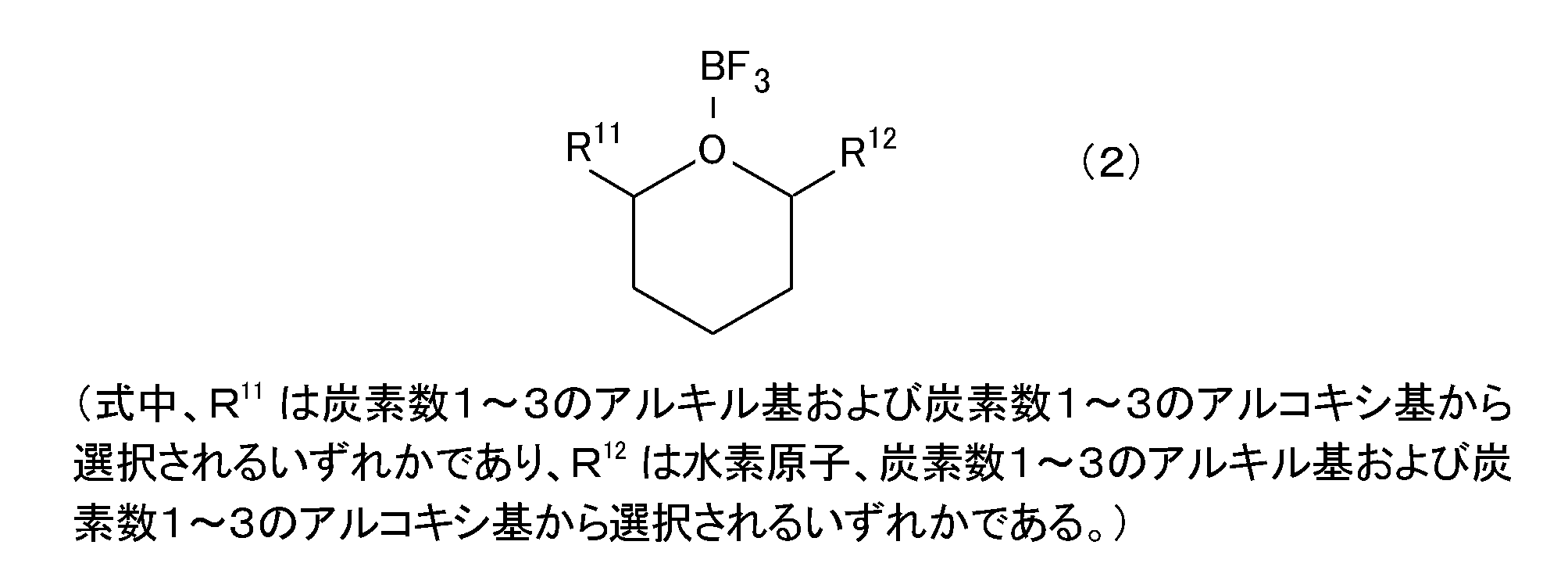
- the BF 3 -cyclic ether complex can be, for example, one or more selected from the group consisting of compounds represented by the following formulas (1) to (6).
- the BF 3 complex of a cyclic ether having no substituent on the ether ring as in the formulas (1) and (4) is advantageous in production because the cyclic ether is easily available.
- an electrolytic solution containing the BF 3 -tetrahydropyran complex represented by the formula (1) as a solvent is preferable because it can be an electrolytic solution having an oxidation potential greatly exceeding 5V.
- Such an electrolytic solution is useful as an electrolytic solution used for, for example, a 5V class battery.
- BF 3 complexes of cyclic ethers having one or more substituents on the ether ring as in formulas (2), (3), (5), (6) are compared to those not having the above substituents.
- the bulkiness of the cyclic ether portion is large. Therefore, according to the electrolytic solution containing such a BF 3 complex as a solvent (typically a main solvent), damage to graphite can be prevented to a higher degree.
- a substituent is introduced into a cyclic ether having no substituent, the symmetry of the molecule is lost, so that the crystallinity is lowered, and thereby the melting point can be lowered.
- a BF 3 complex of a cyclic ether having a substituent can exhibit a lower melting point than a BF 3 complex of a cyclic ether having no substituent.
- the low melting point of the BF 3 -cyclic ether complex is advantageous, for example, in terms of low temperature characteristics of an electrolyte solution containing the complex as a solvent (typically a main solvent).
- the introduction of the substituent can improve the oxidation potential as compared with a cyclic ether having no substituent.
- the BF 3 -cyclic ether complex constituting the electrolytic solution disclosed herein is produced, for example, by passing BF 3 gas through a raw material organic substance (typically, a cyclic ether corresponding to the target complex structure). can do.
- BF 3 - as preferred method of cyclic ether complex, BF 3 and an object - a cyclic ether corresponding to cyclic ether complex, BF 3 to be substituted ethers different from the cyclic ether is coordinated to BF 3 -
- a method of removing the substituted ether from the reaction system after mixing with the substituted ether complex can be mentioned.
- This method utilizes an ether exchange reaction between a BF 3 -substituted ether complex and a cyclic ether.
- Such a manufacturing method has an advantage that the material to be used is easily handled as compared with the above-described method in which BF 3 gas is passed.
- the production method using the ether exchange reaction will be specifically described by taking as an example the production of the BF 3 -THP complex represented by the above formula (4). That is, BF 3 -diethyl ether complex (BF 3 -substituted ether complex) and THP (cyclic ether corresponding to the structure of the target product) are mixed, and the diethyl ether part of the BF 3 -diethyl ether complex is substituted with THP.
- the target BF 3 -THP complex is synthesized.
- BF 3 -substituted ether complex those which are liquid at room temperature can be preferably used.
- liquid at normal temperature means a state having fluidity at 25 ° C.
- Such a BF 3 -substituted ether complex is preferable because it can be easily mixed with a cyclic ether (typically liquid at room temperature) and has good handleability. Since the ether portion of the BF 3 -substituted ether complex is removed from the reaction system by the above removal step (eg, distilled off by distillation under reduced pressure), the ether that is easily removed in the removal step coordinates to BF 3.
- the BF 3 -substituted ether complex is preferably used.
- the substituted ether preferably has a boiling point in the range of ⁇ 50 ° C. to 70 ° C., for example. Further, a substituted ether having a molecular weight in the range of, for example, 40 to 200 (more preferably 46 to 150) is preferable.
- the kind of the substituted ether preferably used may vary depending on the kind of the cyclic ether substituted with the ether, but usually diethyl ether or dimethyl ether can be preferably used. Particular preference is given to using diethyl ether. This is because the BF 3 -diethyl ether complex is commercially available.
- the mixing ratio of the BF 3 -substituted ether complex and the cyclic ether is not particularly limited. Usually, it is appropriate that the molar ratio of BF 3 -substituted ether complex: cyclic ether is about 1: 0.5 to 2.0, for example, 1: 0.9 to 1.5 (typically It is preferably about 1: 1 to 1.3). BF 3 - a little longer than the equivalent cyclic ethers against the substituted ether complex (e.g., in excess of about 5-30% in moles) by mixing, BF 3 - be produced efficiently cyclic ether complex it can.
- the temperature at which the mixture is stirred after the BF 3 -substituted ether complex and the cyclic ether are mixed is not particularly limited. Usually, it is appropriate to set the temperature at which the reaction system can be maintained in a liquid state (in other words, the temperature at which the ether exchange reaction can proceed as a liquid phase reaction). For example, a temperature of about 0 ° C. to 80 ° C. is preferable. Can be adopted. From the viewpoint of energy cost, etc., stirring may be performed at room temperature (typically about 10 ° C to 30 ° C), or under heating conditions (for example, 35 ° C to 60 ° C) to promote the progress of the ether exchange reaction. May be.
- the method of removing the substituted ether portion of the BF 3 -substituted ether complex from the reaction system includes, for example, a method of circulating an inert gas such as nitrogen gas or argon gas, a heating method, a reduced pressure And the like. You may use combining these methods suitably.
- Nitrogen gas, argon gas, etc. can be illustrated as an inert gas used in the removal method which distribute
- the inert gas is preferably stirred at room temperature to about 60 ° C.
- the stirring time is not particularly limited, but it is usually suitable to be 50 hours or longer (for example, about 50 hours to 150 hours).
- a preferable heating temperature may vary depending on the type of BF 3 -substituted ether complex or cyclic ether to be used, but it is usually appropriate to be in the range of 40 ° C to 90 ° C.
- the preferred degree of reduced pressure may vary depending on the type of BF 3 -substituted ether complex or cyclic ether used, but is usually 2.5 ⁇ 10 4 to 700 ⁇ 10 4 Pa (approximately 200 mmHg). It is appropriate to set it to about 500 mmHg).
- the electrolytic solution according to the present invention uses any of the BF 3 -cyclic ether complexes disclosed herein (which may be a BF 3 -cyclic ether complex produced by any of the methods disclosed herein) as a main solvent.
- the solvent constituting the electrolytic solution is preferably a BF 3 -cyclic ether complex, more preferably 75% by mass or more, and still more preferably 90% by mass or more.
- Substantially all of the solvent may be a BF 3 -cyclic ether complex.
- the ratio of the total amount to the whole solvent is preferably in the above range.
- the electrolytic solution disclosed herein may contain a solvent other than the BF 3 -cyclic ether complex as a subcomponent (subsolvent).
- a solvent other than the BF 3 -cyclic ether complex as a subcomponent (subsolvent).
- the melting point of the BF 3 -cyclic ether complex is higher than 10 ° C. (in a composition containing a plurality of types of BF 3 -cyclic ether complexes, the mixture of these complexes solidifies at 10 ° C. or higher)
- a solvent having a melting point lower than that of the BF 3 -cyclic ether complex is preferably used as a secondary solvent. It is preferable to select a solvent that can be uniformly mixed with the BF 3 -cyclic ether complex.
- Examples of materials that can be used as the co-solvent include carbonates such as ethylene carbonate (EC), propylene carbonate (PC), dimethyl carbonate (DMC), diethyl carbonate (DEC), and ethyl methyl carbonate (EMC);
- Examples include ethers such as dipropyl ether; nitriles such as methoxypropionitrile and acetonitrile; esters such as methyl acetate; amines such as triethylamine; alcohols such as methanol; ketones such as acetone; Of these, one kind may be used alone, or two or more kinds may be used in combination. Among these, one or more selected from carbonates can be preferably used.
- a cyclic ether may be used as the co-solvent.
- the electrolyte may contain a cyclic ether corresponding to the complex as a secondary solvent.
- Other examples of materials that may be used as the auxiliary solvent include BF 3 complex organic substances other than the cyclic ether (e.g., chain ethers) is coordinated to BF 3.
- the supporting electrolyte contained in the electrolytic solution disclosed herein is not particularly limited as long as it is soluble in a solvent containing the BF 3 -cyclic ether complex as a main component.
- the electrolyte solution may contain a suitable supporting electrolyte depending on the application.
- various lithium salts, sodium salts, quaternary ammonia salts, and the like can be used as the supporting electrolyte.
- An electrolytic solution containing a lithium salt as a supporting electrolyte is particularly preferable.
- the electrolytic solution having such a composition can be useful as an electrolytic solution for a lithium secondary battery (such as a lithium ion battery).
- the various lithium salt known to be able to function as a supporting electrolyte in the electrolyte solution of a lithium secondary battery can be used.
- the electrolytic solution disclosed herein include LiPF 6 , LiBF 4 , LiN (SO 2 CF 3 ) 2 (hereinafter sometimes referred to as “LiTFSI”), LiN (SO 2 C 2 F 5 ) 2. (Hereinafter sometimes referred to as “LiBETI”), LiCF 3 SO 3 , LiC 4 F 9 SO 3 , LiC (SO 2 CF 3 ) 3 , LiClO 4, etc. It may be an electrolytic solution containing a salt as a supporting electrolyte.
- the concentration of the supporting electrolyte is not particularly limited, but it is usually preferable that the concentration is such that the supporting electrolyte can be stably dissolved at least at 25 ° C. (for example, precipitation of the electrolyte is not observed).
- an electrolyte containing about 0.1 mol or more (for example, about 0.1 to 3 mol) of a supporting electrolyte in 1 kg of electrolyte is preferable, and about 0.2 mol or more (for example, about 0.2 to 2 mol). More preferably, the electrolytic solution is contained.
- the electrolytic solution having such a composition can be preferably prepared, for example, by preparing a BF 3 -cyclic ether complex and mixing the complex with a supporting electrolyte.
- the BF 3 -cyclic ether complex can be prepared by producing a BF 3 -cyclic ether complex using the ether exchange reaction.
- these mixed solvents and the above supporting electrolyte may be mixed.
- a lithium salt may be dissolved in a part of the solvent component, and the lithium solution and the remaining solvent component may be mixed.
- Such mixing operation is preferably performed in a dry inert gas (for example, nitrogen gas) atmosphere.
- the electrolytic solution disclosed herein can be used as an electrolytic solution for various electrochemical devices (batteries, sensors, etc.). Preferably, it is used as an electrolyte for batteries.
- the “battery” is a term indicating a general power storage device that can extract electric energy, and includes a primary battery and a secondary battery.
- the “secondary battery” is a concept including so-called storage batteries such as lithium secondary batteries, nickel hydride batteries and nickel cadmium batteries, and power storage elements such as electric double layer capacitors.
- a lithium secondary battery typically a lithium ion battery.
- the lithium secondary battery generally has a configuration in which a positive electrode and a negative electrode including an electrode active material capable of inserting and extracting lithium ions are housed in a container (can be a laminate film container or the like) together with an electrolytic solution.
- a positive electrode active material an oxide-based positive electrode active material having a layered structure, an oxide-based positive electrode active material having a spinel structure, and the like used for a general lithium secondary battery can be used.
- a positive electrode active mainly composed of lithium cobalt complex oxide (for example, LiCoO 2 ), lithium nickel complex oxide (typically LiNiO 2 ), lithium manganese complex oxide (for example, LiMn 2 O 4 ), or the like. Substances can be used.
- the positive electrode may be in a form in which such a positive electrode active material is adhered to a positive electrode current collector as a positive electrode mixture together with a conductive material, a binder (binder) and the like as necessary.
- a conductive material a carbon material such as carbon black (acetylene black or the like), a conductive metal powder such as nickel powder, or the like can be used.
- a binder for example, fluorine resins such as polyvinylidene fluoride (PVDF), polytetrafluoroethylene (PTFE), and ethylenetetrafluoroethylene (ETFE) can be preferably used.
- PVDF polyvinylidene fluoride
- PTFE polytetrafluoroethylene
- ETFE ethylenetetrafluoroethylene
- As the positive electrode current collector a rod-like body, a plate-like body, a foil-like body, a net-like body or the like mainly composed of aluminum, nickel, titanium, stainless steel, or the like
- the negative electrode active material examples include carbon materials such as natural graphite, mesocarbon microbeads (MCMB), highly oriented graphite (HOPG), hard carbon, and soft carbon.
- MCMB mesocarbon microbeads
- HOPG highly oriented graphite
- hard carbon hard carbon
- soft carbon soft carbon
- a single metal such as lithium or tin or a metal material such as an alloy
- metal compounds such as metal oxides (for example, lithium titanates such as Li 4 Ti 6 O 12 ), metal sulfides, and metal nitrides.
- the negative electrode may be in a form in which such a negative electrode active material is attached to a negative electrode current collector as a negative electrode mixture together with a binder (binder) or the like as necessary.
- binder the same as the positive electrode can be used.
- the negative electrode current collector a rod-like body, a plate-like body, a foil-like body, a net-like body or the like mainly composed of copper,
- the electrolytic solution disclosed herein has a configuration in which a carbon material (such as natural graphite) having a graphite structure is used as an electrode active material in at least one of the positive electrode and the negative electrode (typically, at least the negative electrode). It can be preferably applied to lithium secondary batteries.
- a carbon material such as natural graphite
- the negative electrode typically, at least the negative electrode
- the use of an electrolytic solution in which a supporting electrolyte is dissolved in a solvent composed of a BF 3 -chain ether complex makes the graphite structure susceptible to damage. This is because it can be prevented or suppressed.
- Application to a lithium secondary battery provided with an electrode using substantially only graphite as the negative electrode active material is particularly preferable.
- the effect of preventing damage to the graphite structure as described above by employing the electrolytic solution of the present invention is the effect of using other carbon materials having a graphite structure as an active material (that is, other than lithium secondary batteries). It can be similarly applied to chemical devices.
- a separator is interposed between the positive electrode and the negative electrode.
- a separator the thing similar to the separator used for a general lithium secondary battery can be used, and it does not specifically limit.
- a porous sheet made of a resin such as polyethylene (PE), polypropylene (PP), polyester, cellulose, or polyamide, a nonwoven fabric, or the like can be used.
- the shape (outer shape of the container) of the lithium secondary battery is not particularly limited, and may be, for example, a cylindrical shape, a square shape, a coin shape, or the like.
- Example 1 Electrolytic solution using BF 3 -THP complex as solvent> Tetrahydropyran (THP) 3.00 g and BF 3 -diethyl ether complex 3.95 g were charged into a reaction vessel and stirred at 45 ° C. for 3 days under a nitrogen gas flow to advance the ether exchange reaction. Thereafter, vacuum distillation was performed twice to obtain 3.21 g of BF 3 -THP complex as a colorless liquid. The obtained BF 3 -THP complex was subjected to 1 H-NMR and 13 C-NMR measurements, and it was confirmed from the NMR spectrum that the desired BF 3 -THP complex was synthesized. The melting point of this BF 3 -THP complex was ⁇ 18.2 ° C. The spectrum data is shown below. The results of 1 H-NMR are shown in FIG. Further, the results of IR measurement are shown in FIG.
- Example 2 Electrolyte solution using BF 3 -THF complex as solvent> A commercially available boron trifluoride tetrahydrofuran (BF 3 -THF) complex was distilled under reduced pressure, treated with metallic lithium and purified by rectification. In a glove box under an argon atmosphere, was added LiPF 6 in BF 3-THF complex purified in the above (melting point -3.7 ° C.), stirring and mixing for 24 hours, 0.1 mol to BF 3-THF complex / An electrolyte solution in which kg of LiPF 6 was dissolved was prepared. Similarly, an electrolytic solution in which 0.1 mol / kg of LiBF 4 was dissolved in a BF 3 -THF complex was prepared.
- BF 3 -THF boron trifluoride tetrahydrofuran
- electrolyte solutions in which LiTFSI was dissolved in the BF 3 -THF complex at concentrations of 0.1 mol / kg, 0.5 mol / kg, 1.0 mol / kg, and 2.0 mol / kg were prepared in the same manner.
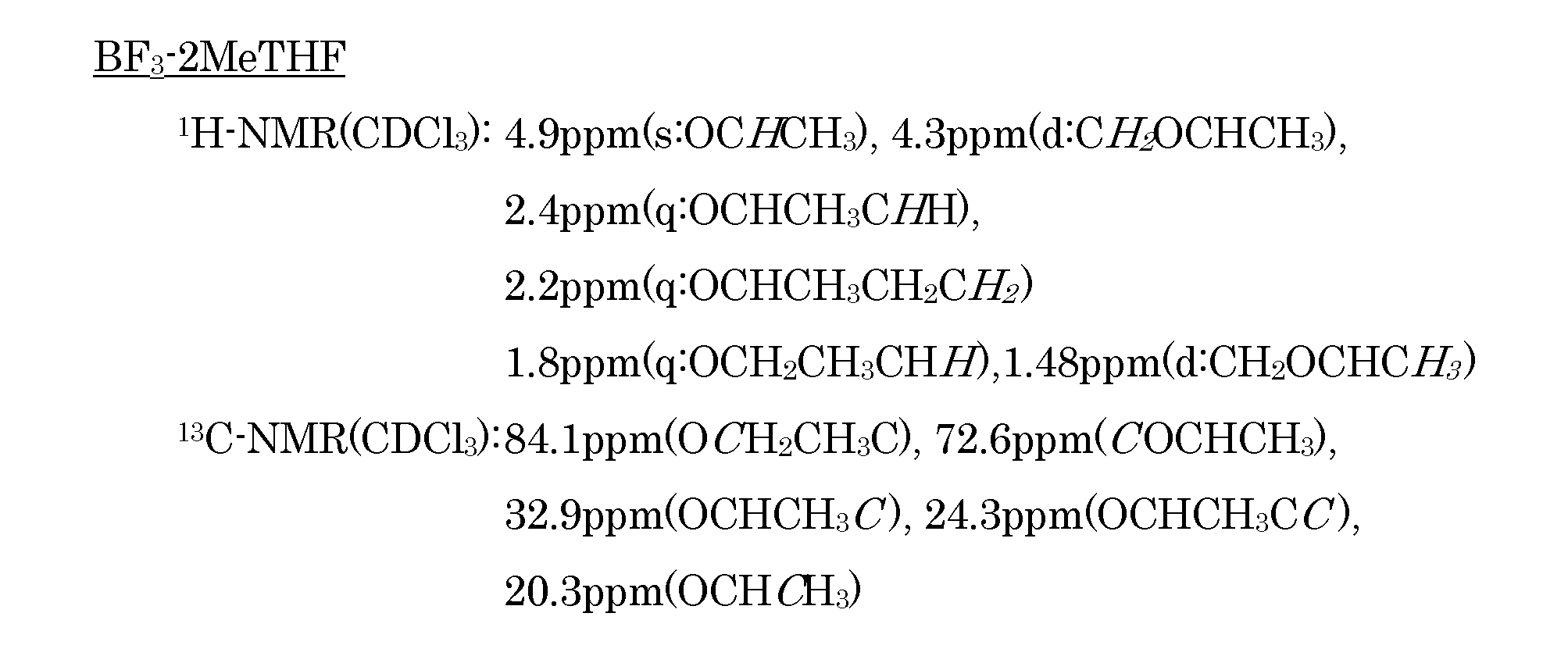
- Example 3 Electrolyte solution using BF 3 -2MeTHF complex as solvent> 5.9 g of 2-methyltetrahydrofuran (2MeTHF) and 10.0 g of BF 3 -diethyl ether complex were charged into a reaction vessel and stirred at 40 ° C. for 2 days under a nitrogen gas flow to advance the ether exchange reaction. Thereafter, vacuum distillation, metal lithium treatment and rectification were performed to obtain 4.6 g of a BF 3 -2MeTHF complex as a colorless liquid. 1 H-NMR and 13 C-NMR of the obtained BF 3 -2MeTHF complex were measured, and from the results, it was confirmed that the target BF 3 -2MeTHF complex was synthesized. The melting point of this BF 3 -2MeTHF complex was ⁇ 37.5 ° C. The spectrum data is shown below.
- LiPF 6 was added to the complex obtained above and mixed with stirring for 24 hours to prepare an electrolyte solution in which 0.1 mol / kg of LiPF 6 was dissolved in the BF 3 -2MeTHF complex. did. Similarly, an electrolytic solution in which 0.5 mol / kg LiTFSI was dissolved in a BF 3 -2MeTHF complex was prepared.
- the oxidation potential of the electrolyte solution containing LiPF 6 as the supporting electrolyte was measured.
- the oxidation potential was measured by a linear sweep voltammetry method using a sealed bipolar cell using platinum as a working electrode, a counter electrode and metallic lithium as a reference electrode. During the measurement, the potential of the working electrode was swept from the immersion potential to the high potential side. The measurement temperature was 30 ° C., and the sweep rate was 0.1 mV / second.
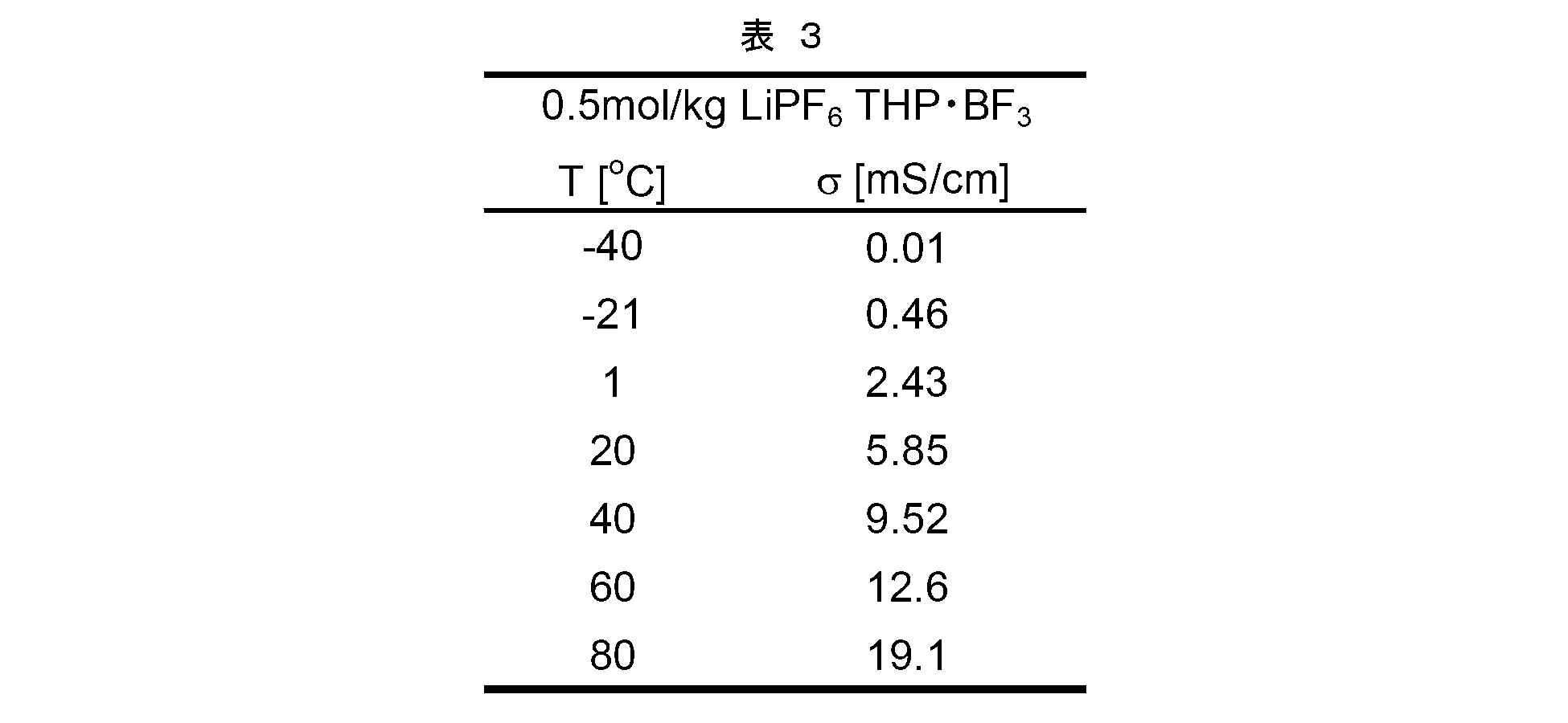
- the ionic conductivity ⁇ [S / cm] of the electrolytic solution prepared in Example 1 was measured. The measurement was performed by an AC impedance method using a sealed bipolar cell equipped with a stainless steel (SUS) electrode. The measurement temperature was raised stepwise and the ionic conductivity was measured at each temperature. As a control, the ionic conductivity of an electrolytic solution having a composition in which the solvent of each electrolytic solution was changed from the BF 3 -cyclic ether complex to the corresponding cyclic ether was measured in the same manner. The results obtained are shown in the table below and in FIG.
- BF 3 electrolytic solution of LiPF 6 0.5M is dissolved in -THP is, BF 3 melting point of -THP Despite the relatively high -18.2 ° C., -20 Even at 0 ° C., the ion conductivity ⁇ showed a relatively good ion conductivity of the order of 10 ⁇ 1 mS / cm.
- an electrolytic solution in which 0.5 M LiTFSI is dissolved in BF 3 -THP uses a conventional EC-DEC solvent (carbonate solvent) having an ionic conductivity ⁇ of the order of 10 mS / cm in a temperature range above room temperature. The ionic conductivity was higher than that of a general lithium secondary battery electrolyte.
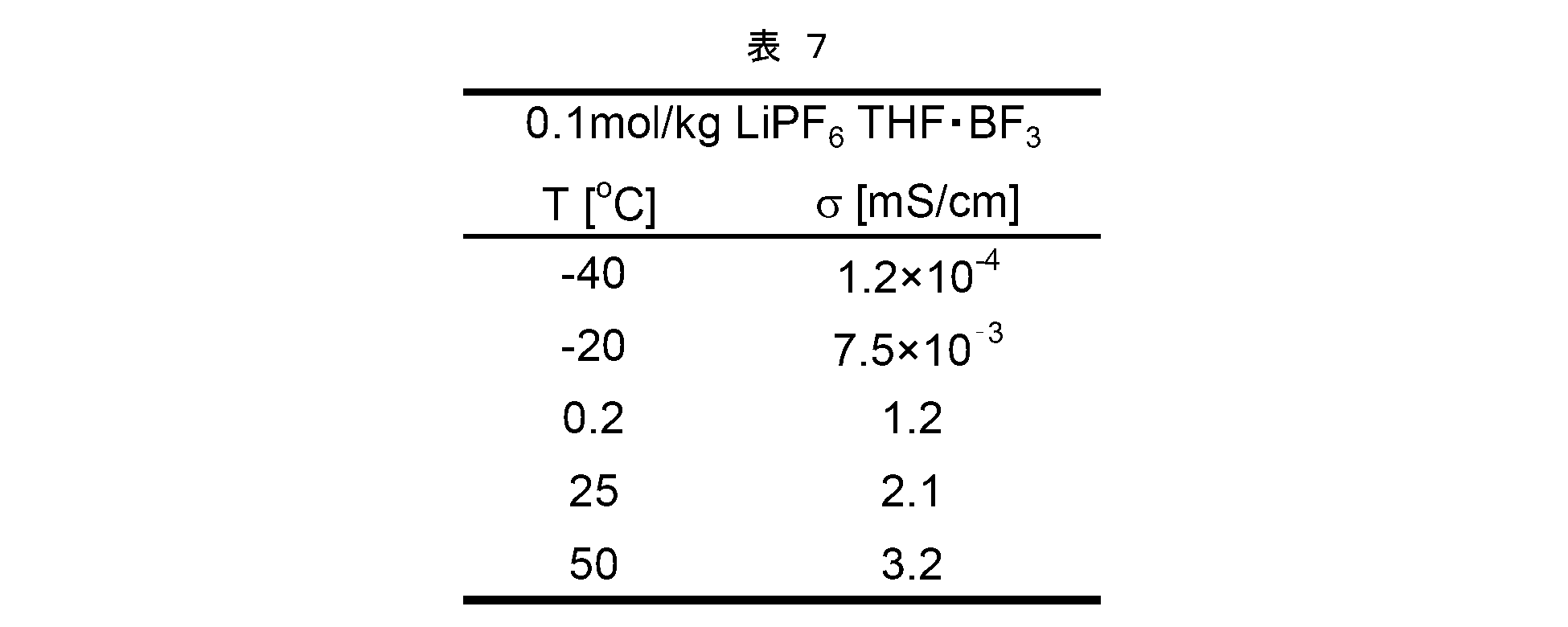
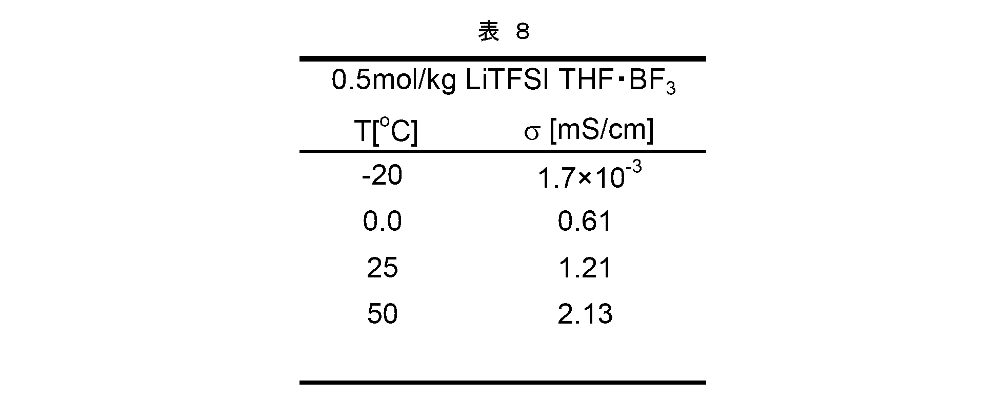
- the ionic conductivity ⁇ [S / cm] of the electrolytic solution prepared in Example 2 was measured in the same manner as described above.
- the ionic conductivity ⁇ of a BF 3 -THF complex containing no supporting electrolyte was measured in the same manner. The results obtained are shown in the table below and in FIG.
- the electrolytic solution in which 0.1M LiPF 6 is dissolved in BF 3 -THF has an ionic conductivity ⁇ of 2.1 mS at 25 ° C. despite a relatively low lithium salt concentration. A relatively good ion conductivity of / cm was exhibited.
- concentration of the lithium salt increased, the low temperature characteristics tended to improve due to the freezing point depression.
- an ionic conductivity ⁇ is 2.4 ⁇ 10 ⁇ 1 mS / cm even at ⁇ 20 ° C. The value was higher than that of a typical lithium secondary battery electrolyte.
- the electrolytic solution using BF 3 -2MeTHF as a solvent has an ionic conductivity ⁇ of the order of 10 mS / cm in the temperature range of 0 ° C. or higher, and 10 ⁇ 1 mS even in the temperature range of ⁇ 10 ° C. or lower. A relatively high ionic conductivity of / cm order was exhibited.
- an electrolytic solution in which 1M LiPF 6 was dissolved in BF 3 -2MeTHF exhibited a relatively good ionic conductivity of 2.1 mS / cm at 25 ° C., although the lithium salt concentration was relatively low.
- LiCoO 2 as a positive electrode active material was mixed with N-methylpyrrolidone (NMP) together with carbon black (CB) and polyvinylidene fluoride (PVDF) to prepare a positive electrode mixture paste. This was applied to an aluminum foil (positive electrode current collector) and dried to prepare a positive electrode sheet having a positive electrode active material layer on one side of the current collector. This positive electrode sheet was punched into a predetermined size to obtain a positive electrode.
- Graphite as a negative electrode active material was mixed with NMP together with PVDF to prepare a negative electrode mixture paste. This was applied to a copper foil (negative electrode current collector) and dried to prepare a negative electrode sheet having a negative electrode active material layer on one side of the current collector. This negative electrode sheet was punched into a predetermined size to obtain a negative electrode.
- DMC was added to 0.5 M LiTFSI THP ⁇ BF 3 produced in Example 1 to prepare an electrolytic solution (electrolytic solution A) containing 10% by mass of DMC.
- electrolytic solution A electrolytic solution
- the positive electrode and the negative electrode are placed opposite to each other with a separator (a porous polypropylene sheet is used here) and incorporated in a stainless steel container together with the electrolytic solution A, and a coin type (diameter: 20 mm, thickness: 3.2 mm) A 2032 type) lithium ion battery was constructed.
- This lithium ion battery was charged and discharged for 3 cycles under the conditions of a current density of 0.57 mA / cm 2 , 0.5 C, and a cutoff voltage of 4.2 V to 2.5 V. Thereafter, the battery was disassembled, and the surface state of the negative electrode active material layer was observed with a scanning electron microscope (SEM). The obtained SEM image is shown in FIG.
- SEM scanning electron microscope
- Example 2 was added to the DMC 1.0M LiTFSI THF ⁇ BF 3 electrolytic solution prepared in, and 1.0M LiTFSI THF ⁇ BF 3 electrolyte containing 10 wt% of the DMC (electrolytic solution B) was prepared. 3 cycles of charge and discharge were performed in the same manner as above except that the electrolyte solution B was used instead of the electrolyte solution A, and then the surface state of the negative electrode active material layer was observed with an SEM. The obtained SEM image is shown in FIG.
- LiTFSI was added to and mixed with the BF 3 -diethyl ether (Et 2 O) complex to prepare a solution in which 1.0 M LiTFSI was dissolved in the BF 3 -diethyl ether complex (1.0 M LiTFSI Et 2 O ⁇ BF 3 ). did.
- DMC was added to this solution to prepare a 1.0 M LiTFSI Et 2 O ⁇ BF 3 electrolytic solution (electrolytic solution C) containing 10% by mass of DMC.
- electrolytic solution C electrolytic solution containing 10% by mass of DMC.
Landscapes
- Chemical & Material Sciences (AREA)
- Chemical Kinetics & Catalysis (AREA)
- Electrochemistry (AREA)
- General Chemical & Material Sciences (AREA)
- Inorganic Chemistry (AREA)
- Engineering & Computer Science (AREA)
- Manufacturing & Machinery (AREA)
- Physics & Mathematics (AREA)
- Condensed Matter Physics & Semiconductors (AREA)
- General Physics & Mathematics (AREA)
- Organic Chemistry (AREA)
- Secondary Cells (AREA)
Abstract
Description
なお、本出願は2008年9月11日に出願された日本国特許出願2008-233366号に基づく優先権を主張しており、その出願の全内容は本明細書中に参照として組み入れられている。
本発明は、BF3錯体を主溶媒とする電解液であって、グラファイト構造を損傷し難い電解液を提供することを目的とする。本発明の他の目的は、かかる電解液の製造方法および該電解液を備えた電池を提供することである。





好ましく用いられる被置換エーテルの種類は、該エーテルと置換する環状エーテルの種類等によっても異なり得るが、通常は、ジエチルエーテルまたはジメチルエーテルを好ましく採用することができる。ジエチルエーテルを用いることが特に好ましい。BF3-ジエチルエーテル錯体は市販品として入手可能であるからである。
上記不活性ガスを流通させる除去方法において使用する不活性ガスとしては、窒素ガスやアルゴンガス等を例示することができる。かかる不活性ガスを流通させる際には、上記混合物を室温~60℃程度で撹拌することが好ましい。撹拌時間は特に限定されないが、通常は50時間以上(例えば50時間~150時間程度)とすることが適当である。また、上記加熱による除去方法において、好ましい加熱温度は、使用するBF3-被置換エーテル錯体や環状エーテルの種類によって異なり得るが、通常は40℃~90℃の範囲とすることが適当である。また、上記減圧による除去方法において、好ましい減圧度は、使用するBF3-被置換エーテル錯体や環状エーテルの種類によって異なり得るが、通常は2.5×10⁴~700×104Pa(概ね200mmHg~500mmHg)程度とすることが適当である。
正極活物質としては、一般的なリチウム二次電池に用いられる層状構造の酸化物系正極活物質、スピネル構造の酸化物系正極活物質等を用いることができる。例えば、リチウムコバルト系複合酸化物(例えばLiCoO2)、リチウムニッケル系複合酸化物(典型的にはLiNiO2)、リチウムマンガン系複合酸化物(例えばLiMn2O4)等を主成分とする正極活物質を用いることができる。上記正極は、このような正極活物質を、必要に応じて導電材、結着剤(バインダ)等とともに正極合材として正極集電体に付着させた形態であり得る。導電材としては、カーボンブラック(アセチレンブラック等)のような炭素材料、ニッケル粉末等の導電性金属粉末等を用いることができる。結着剤としては、例えば、ポリフッ化ビニリデン(PVDF)、ポリテトラフルオロエチレン(PTFE)、エチレンテトラフルオロエチレン(ETFE)等のフッ素系樹脂を好ましく用いることができる。正極集電体としては、アルミニウム、ニッケル、チタン、ステンレススチール等を主体とする棒状体、板状体、箔状体、網状体等を使用することができる。
なお、本発明の電解液を採用することにより上記のようにグラファイト構造の損傷を防止する効果は、グラファイト構造を有する炭素材料を活物質として用いた他の(すなわちリチウム二次電池以外の)電気化学デバイスにおいても同様に発揮され得る。
テトラヒドロピラン(THP)3.00gとBF3-ジエチルエーテル錯体3.95gとを反応容器に仕込み、窒素ガスフロー下、45℃で3日間攪拌することでエーテル交換反応を進行させた。その後、減圧蒸留を2回行って、BF3-THP錯体3.21gを無色の液体として得た。
得られたBF3-THP錯体につき1H-NMRおよび13C-NMR測定を行い、それらのNMRスペクトルから目的のBF3-THP錯体が合成されたことを確認した。このBF3-THP錯体の融点は-18.2℃であった。スペクトルデータを以下に示す。また、1H-NMRの結果を図1に示す。さらにIR測定を行った結果を図2に示す。

市販の三フッ化ホウ素テトラヒドロフラン(BF3-THF)錯体を減圧蒸留し、金属リチウムで処理を行い精留を行って精製した。アルゴン雰囲気下のグローブボックス内において、上記で精製したBF3-THF錯体(融点 -3.7℃)にLiPF6を添加し、24時間攪拌混合して、BF3-THF錯体に0.1mol/kgのLiPF6が溶解した電解液を調製した。同様にして、BF3-THF錯体に0.1mol/kgのLiBF4が溶解した電解液を調製した。さらに、BF3-THF錯体にLiTFSIが、0.1mol/kg、0.5mol/kg、1.0mol/kg、2.0mol/kgの濃度でそれぞれ溶解した電解液を同様にして調製した。
2-メチルテトラヒドロフラン(2MeTHF)5.9gとBF3-ジエチルエーテル錯体10.0gとを反応容器に仕込み、窒素ガスフロー下、40℃で2日間攪拌することでエーテル交換反応を進行させた。その後、減圧蒸留、金属リチウム処理および精留を行って、BF3-2MeTHF錯体4.6gを無色の液体として得た。
得られたBF3-2MeTHF錯体の1H-NMRおよび13C-NMRを測定し、その結果から目的のBF3-2MeTHF錯体が合成されたことを確認した。このBF3-2MeTHF錯体の融点は-37.5℃であった。スペクトルデータを以下に示す。

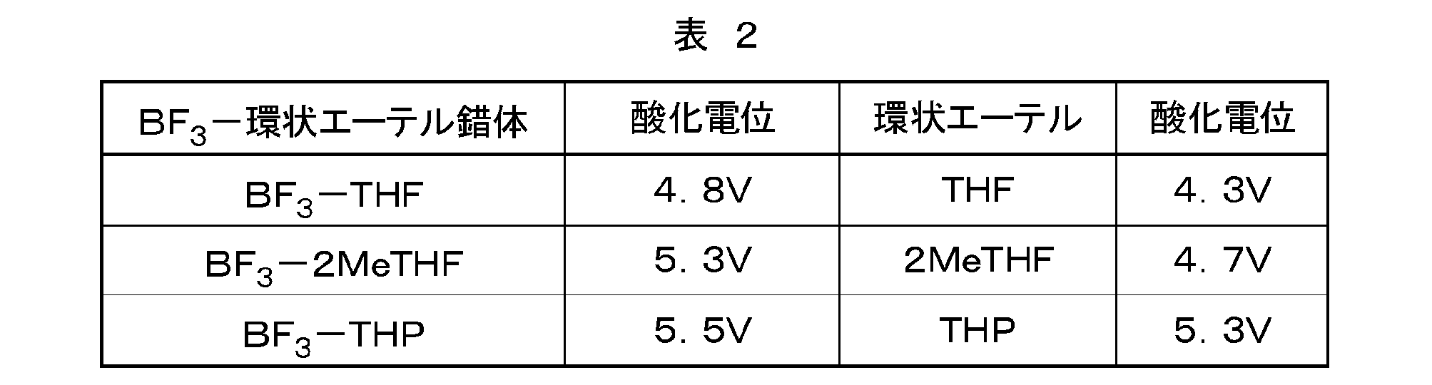
例1~3で調製した電解液(表1参照)のうち、支持電解質としてLiPF6を含む電解液について酸化電位を測定した。酸化電位の測定は、作用極に白金、対極および参照極に金属リチウムを用いた密閉二極式セルを使用して、リニアスイープボルタンメトリー法により行った。測定の際、作用電極の電位を浸漬電位から高電位側に掃引した。測定温度は30℃、掃引速度は0.1mV/秒とした。対照として、各電解液の溶媒をBF3-環状エーテル錯体から対応する環状エーテルに変更した組成の電解液を調製し、同様に酸化電位を測定した。それらの結果を表2に示す。
例1で調製した電解液のイオン導電率σ[S/cm]を測定した。測定は、ステンレススチール(SUS)電極を備えた密閉二極式セルを使用して交流インピーダンス法により行った。測定温度を段階的に上げ、各温度においてイオン導電率を測定した。対照として、各電解液の溶媒をBF3-環状エーテル錯体から対応する環状エーテルに変更した組成の電解液のイオン導電率を同様に測定した。得られた結果を以下の表および図3に示す。




正極活物質としてのLiCoO2を、カーボンブラック(CB)およびポリフッ化ビニリデン(PVDF)とともにN-メチルピロリドン(NMP)と混合して正極合剤ペーストを調製した。これをアルミニウム箔(正極集電体)に塗布して乾燥させることにより、集電体の片面に正極活物質層を有する正極シートを作製した。この正極シートを所定の大きさに打ち抜いて正極とした。
負極活物質としてのグラファイトを、PVDFとともにNMPと混合して負極合剤ペーストを調製した。これを銅箔(負極集電体)に塗布して乾燥させることにより、集電体の片面に負極活物質層を有する負極シートを作製した。この負極シートを所定の大きさに打ち抜いて負極とした。
このリチウムイオン電池に対し、電流密度0.57mA/cm2、0.5C、カットオフ電圧4.2V-2.5Vの条件で3サイクルの充放電を行った。その後、該電池を分解し、負極活物質層の表面状態を走査型電子顕微鏡(SEM)で観察した。得られたSEM像を図6に示す。
Claims (6)
- 溶媒と支持電解質とを含む電解液であって、
前記溶媒は、BF3に環状エーテルが配位したBF3-環状エーテル錯体を主成分とする、電解液。 - 前記環状エーテルは:
置換基を有してもよいテトラヒドロフラン;および、
置換基を有してもよいテトラヒドロピラン;
から選択される一種または二種以上である、請求項1に記載の電解液。 - 前記環状エーテルは、テトラヒドロフラン、2-メチルテトラヒドロフランおよびテトラヒドロピランから選択される一種または二種以上である、請求項2に記載の電解液。
- 請求項1に記載の電解液を備える、電池。
- 前記支持電解質はリチウム塩であり、グラファイト構造を有する炭素材料を電極活物質に用いたリチウム二次電池として構成されている、請求項4に記載の電池。
- 請求項1に記載の電解液を製造する方法であって:
前記環状エーテルとは異なる被置換エーテルがBF3に配位したBF3-被置換エーテル錯体と前記環状エーテルとを混合し、その後、前記被置換エーテルを反応系内から除去することにより、前記BF3-環状エーテル錯体を得ること;および、
前記BF3-環状エーテル錯体と前記支持電解質とを混合すること;
を包含する、電解液製造方法。
Priority Applications (3)
| Application Number | Priority Date | Filing Date | Title |
|---|---|---|---|
| CN200980135538.0A CN102150314B (zh) | 2008-09-11 | 2009-09-10 | 电解液和其用途 |
| US13/061,968 US8986896B2 (en) | 2008-09-11 | 2009-09-10 | Electrolyte solution and use therefor |
| KR1020117008160A KR101328317B1 (ko) | 2008-09-11 | 2009-09-10 | 전해액 및 그 이용 |
Applications Claiming Priority (2)
| Application Number | Priority Date | Filing Date | Title |
|---|---|---|---|
| JP2008233366A JP5306749B2 (ja) | 2008-09-11 | 2008-09-11 | 電気化学デバイス |
| JP2008-233366 | 2008-09-11 |
Publications (1)
| Publication Number | Publication Date |
|---|---|
| WO2010029971A1 true WO2010029971A1 (ja) | 2010-03-18 |
Family
ID=42005221
Family Applications (1)
| Application Number | Title | Priority Date | Filing Date |
|---|---|---|---|
| PCT/JP2009/065845 Ceased WO2010029971A1 (ja) | 2008-09-11 | 2009-09-10 | 電解液およびその利用 |
Country Status (5)
| Country | Link |
|---|---|
| US (1) | US8986896B2 (ja) |
| JP (1) | JP5306749B2 (ja) |
| KR (1) | KR101328317B1 (ja) |
| CN (1) | CN102150314B (ja) |
| WO (1) | WO2010029971A1 (ja) |
Cited By (2)
| Publication number | Priority date | Publication date | Assignee | Title |
|---|---|---|---|---|
| CN103222100A (zh) * | 2010-09-24 | 2013-07-24 | 积水化学工业株式会社 | 电解质、电解液、凝胶电解质、电解质膜、凝胶电解质电池的制造方法及锂离子二次电池 |
| CN107408734A (zh) * | 2015-03-16 | 2017-11-28 | 三菱化学株式会社 | 非水系电解液和使用该非水系电解液的非水系电解液二次电池 |
Families Citing this family (13)
| Publication number | Priority date | Publication date | Assignee | Title |
|---|---|---|---|---|
| JP5601549B2 (ja) * | 2010-12-27 | 2014-10-08 | トヨタ自動車株式会社 | 非水電解液およびその利用 |
| JP5464149B2 (ja) * | 2011-01-11 | 2014-04-09 | トヨタ自動車株式会社 | リチウムイオン電池 |
| KR101507450B1 (ko) * | 2012-04-17 | 2015-03-31 | 주식회사 엘지화학 | 성능이 우수한 리튬 이차전지 |
| US20140023920A1 (en) * | 2012-07-20 | 2014-01-23 | Semiconductor Energy Laboratory Co., Ltd. | Secondary battery |
| US9362593B2 (en) * | 2012-12-19 | 2016-06-07 | Toyota Motor Engineering & Manufacturing North America, Inc. | Borohydride solvo-ionic liquid family for magnesium battery |
| CN104112871B (zh) * | 2014-08-05 | 2016-03-09 | 河南大学 | 用于锂二次电池正极活性材料的表面修饰方法 |
| CN105489935B (zh) * | 2016-01-11 | 2018-06-12 | 东莞新能源科技有限公司 | 电解液以及包括该电解液的锂离子电池 |
| CN105845982B (zh) * | 2016-03-31 | 2018-06-05 | 宁德时代新能源科技股份有限公司 | 电解液以及包括该电解液的锂离子电池 |
| CN105742705B (zh) * | 2016-03-31 | 2019-05-07 | 宁德时代新能源科技股份有限公司 | 电解液以及包括该电解液的锂离子电池 |
| CN105789701B (zh) * | 2016-03-31 | 2019-04-02 | 宁德时代新能源科技股份有限公司 | 电解液以及包括该电解液的锂离子电池 |
| US10910672B2 (en) | 2016-11-28 | 2021-02-02 | Toyota Motor Engineering & Manufacturing North America, Inc. | High concentration electrolyte for magnesium battery having carboranyl magnesium salt in mixed ether solvent |
| US10680280B2 (en) | 2017-09-26 | 2020-06-09 | Toyota Jidosha Kabushiki Kaisha | 3D magnesium battery and method of making the same |
| WO2024043649A1 (ko) * | 2022-08-23 | 2024-02-29 | 주식회사 엘지에너지솔루션 | 전해질 조성물 및 이를 포함하는 리튬 금속 전지 |
Citations (4)
| Publication number | Priority date | Publication date | Assignee | Title |
|---|---|---|---|---|
| JPH11149943A (ja) * | 1997-09-18 | 1999-06-02 | Nec Moli Energy Canada Ltd | 再充電可能な非水系リチウム電池の充放電寿命の改善用添加剤 |
| WO2008032795A1 (fr) * | 2006-09-14 | 2008-03-20 | National University Corporation Shizuoka University | Solution électrolytique pour dispositif électrochimique |
| JP2008094825A (ja) * | 2006-09-13 | 2008-04-24 | National Univ Corp Shizuoka Univ | Bf3錯体およびその製造方法 |
| JP2008273893A (ja) * | 2007-05-01 | 2008-11-13 | National Univ Corp Shizuoka Univ | Bf3錯体、およびbf3錯体の製造方法 |
Family Cites Families (7)
| Publication number | Priority date | Publication date | Assignee | Title |
|---|---|---|---|---|
| US4118550A (en) * | 1977-09-26 | 1978-10-03 | Eic Corporation | Aprotic solvent electrolytes and batteries using same |
| JP2634904B2 (ja) | 1989-03-31 | 1997-07-30 | 日立マクセル株式会社 | 有機電解液電池 |
| JPH1126017A (ja) * | 1997-07-08 | 1999-01-29 | Mitsubishi Chem Corp | リチウム二次電池用電解液 |
| JP3336998B2 (ja) | 1998-08-28 | 2002-10-21 | 株式会社豊田中央研究所 | 非水電解液二次電池 |
| US6911280B1 (en) * | 2001-12-21 | 2005-06-28 | Polyplus Battery Company | Chemical protection of a lithium surface |
| KR20060029747A (ko) * | 2004-10-01 | 2006-04-07 | 삼성에스디아이 주식회사 | 리튬이온 이차전지용 전해액 및 이를 포함하는 리튬이온이차전지 |
| US7833660B1 (en) * | 2006-09-07 | 2010-11-16 | The United States Of America As Represented By The Secretary Of The Army | Fluorohaloborate salts, synthesis and use thereof |
-
2008
- 2008-09-11 JP JP2008233366A patent/JP5306749B2/ja not_active Expired - Fee Related
-
2009
- 2009-09-10 US US13/061,968 patent/US8986896B2/en not_active Expired - Fee Related
- 2009-09-10 KR KR1020117008160A patent/KR101328317B1/ko not_active Expired - Fee Related
- 2009-09-10 CN CN200980135538.0A patent/CN102150314B/zh not_active Expired - Fee Related
- 2009-09-10 WO PCT/JP2009/065845 patent/WO2010029971A1/ja not_active Ceased
Patent Citations (4)
| Publication number | Priority date | Publication date | Assignee | Title |
|---|---|---|---|---|
| JPH11149943A (ja) * | 1997-09-18 | 1999-06-02 | Nec Moli Energy Canada Ltd | 再充電可能な非水系リチウム電池の充放電寿命の改善用添加剤 |
| JP2008094825A (ja) * | 2006-09-13 | 2008-04-24 | National Univ Corp Shizuoka Univ | Bf3錯体およびその製造方法 |
| WO2008032795A1 (fr) * | 2006-09-14 | 2008-03-20 | National University Corporation Shizuoka University | Solution électrolytique pour dispositif électrochimique |
| JP2008273893A (ja) * | 2007-05-01 | 2008-11-13 | National Univ Corp Shizuoka Univ | Bf3錯体、およびbf3錯体の製造方法 |
Cited By (5)
| Publication number | Priority date | Publication date | Assignee | Title |
|---|---|---|---|---|
| CN103222100A (zh) * | 2010-09-24 | 2013-07-24 | 积水化学工业株式会社 | 电解质、电解液、凝胶电解质、电解质膜、凝胶电解质电池的制造方法及锂离子二次电池 |
| CN103222100B (zh) * | 2010-09-24 | 2017-09-08 | 积水化学工业株式会社 | 电解质、电解液、凝胶电解质、电解质膜、凝胶电解质电池的制造方法及锂离子二次电池 |
| US10256497B2 (en) | 2010-09-24 | 2019-04-09 | Sekisui Chemical Co., Ltd. | Electrolyte, electrolyte solution, gel electrolyte, electrolyte membrane, method for manufacturing gel electrolyte battery, and lithium ion secondary battery |
| CN107408734A (zh) * | 2015-03-16 | 2017-11-28 | 三菱化学株式会社 | 非水系电解液和使用该非水系电解液的非水系电解液二次电池 |
| CN107408734B (zh) * | 2015-03-16 | 2020-08-18 | 三菱化学株式会社 | 非水系电解液和使用该非水系电解液的非水系电解液二次电池 |
Also Published As
| Publication number | Publication date |
|---|---|
| JP2010067496A (ja) | 2010-03-25 |
| US20110229772A1 (en) | 2011-09-22 |
| CN102150314B (zh) | 2014-02-26 |
| US8986896B2 (en) | 2015-03-24 |
| CN102150314A (zh) | 2011-08-10 |
| KR101328317B1 (ko) | 2013-11-11 |
| KR20110076920A (ko) | 2011-07-06 |
| JP5306749B2 (ja) | 2013-10-02 |
Similar Documents
| Publication | Publication Date | Title |
|---|---|---|
| JP5306749B2 (ja) | 電気化学デバイス | |
| JP6099155B2 (ja) | 二次電池用電解液およびそれを用いた二次電池 | |
| US10176935B2 (en) | Electrolyte composition comprising fluorinated carbonate, and battery comprising the same | |
| JPWO2020054866A1 (ja) | 非水系二次電池 | |
| JP6593802B2 (ja) | ゲル化剤としての無機配位ポリマー | |
| JP5308314B2 (ja) | 蓄電デバイス用非水溶媒および蓄電デバイス用非水電解液、ならびに、これらを用いた蓄電デバイス、リチウム二次電池および電気二重層キャパシタ | |
| KR101297173B1 (ko) | 리튬 이차 전지 | |
| KR20070103296A (ko) | 비수계 2차 전지 | |
| JP2009543318A (ja) | シアノ基を有する非水電解液添加剤及びこれを用いた電気化学素子 | |
| JP2023002647A (ja) | 二官能性ホスホン酸シリルエステルを含む電気化学セル | |
| JP7345502B2 (ja) | 電池用非水電解液及びリチウム二次電池 | |
| WO2008032795A1 (fr) | Solution électrolytique pour dispositif électrochimique | |
| JP4968614B2 (ja) | 二次電池用電解液およびそれを用いた二次電池 | |
| JPWO2018173476A1 (ja) | 非水電解質二次電池 | |
| CN111480257A (zh) | 包含低聚甲硅烷基膦酸酯的电解质组合物 | |
| JP4423277B2 (ja) | リチウム二次電池 | |
| JP2009187880A (ja) | 非水電解液二次電池 | |
| JP2001023688A (ja) | 非水電解液およびそれを用いたリチウム二次電池 | |
| JP2008094825A (ja) | Bf3錯体およびその製造方法 | |
| JPWO2019235469A1 (ja) | 還元型グラフェン系材料 | |
| EP2163537A1 (en) | Asymmetric bf3 complex | |
| JP2020155277A (ja) | 蓄電デバイス用水系電解液及びこの水系電解液を含む蓄電デバイス | |
| JP7200465B2 (ja) | 電池用非水電解液及びリチウム二次電池 | |
| JP6980502B2 (ja) | 電池用非水電解液及びリチウム二次電池 | |
| JP4861671B2 (ja) | リチウム塩およびその利用 |
Legal Events
| Date | Code | Title | Description |
|---|---|---|---|
| WWE | Wipo information: entry into national phase |
Ref document number: 200980135538.0 Country of ref document: CN |
|
| 121 | Ep: the epo has been informed by wipo that ep was designated in this application |
Ref document number: 09813117 Country of ref document: EP Kind code of ref document: A1 |
|
| DPE1 | Request for preliminary examination filed after expiration of 19th month from priority date (pct application filed from 20040101) | ||
| NENP | Non-entry into the national phase |
Ref country code: DE |
|
| ENP | Entry into the national phase |
Ref document number: 20117008160 Country of ref document: KR Kind code of ref document: A |
|
| WWE | Wipo information: entry into national phase |
Ref document number: 13061968 Country of ref document: US |
|
| 122 | Ep: pct application non-entry in european phase |
Ref document number: 09813117 Country of ref document: EP Kind code of ref document: A1 |