WO2010029642A1 - 希土類異方性ボンド磁石の製造方法、磁石成形体の配向処理方法および磁場中成形装置 - Google Patents
希土類異方性ボンド磁石の製造方法、磁石成形体の配向処理方法および磁場中成形装置 Download PDFInfo
- Publication number
- WO2010029642A1 WO2010029642A1 PCT/JP2008/066591 JP2008066591W WO2010029642A1 WO 2010029642 A1 WO2010029642 A1 WO 2010029642A1 JP 2008066591 W JP2008066591 W JP 2008066591W WO 2010029642 A1 WO2010029642 A1 WO 2010029642A1
- Authority
- WO
- WIPO (PCT)
- Prior art keywords
- magnet
- magnetic field
- orientation
- rare earth
- magnetic
- Prior art date
- Legal status (The legal status is an assumption and is not a legal conclusion. Google has not performed a legal analysis and makes no representation as to the accuracy of the status listed.)
- Ceased
Links
Images




Classifications
-
- H—ELECTRICITY
- H01—ELECTRIC ELEMENTS
- H01F—MAGNETS; INDUCTANCES; TRANSFORMERS; SELECTION OF MATERIALS FOR THEIR MAGNETIC PROPERTIES
- H01F41/00—Apparatus or processes specially adapted for manufacturing or assembling magnets, inductances or transformers; Apparatus or processes specially adapted for manufacturing materials characterised by their magnetic properties
- H01F41/02—Apparatus or processes specially adapted for manufacturing or assembling magnets, inductances or transformers; Apparatus or processes specially adapted for manufacturing materials characterised by their magnetic properties for manufacturing cores, coils, or magnets
-
- H—ELECTRICITY
- H01—ELECTRIC ELEMENTS
- H01F—MAGNETS; INDUCTANCES; TRANSFORMERS; SELECTION OF MATERIALS FOR THEIR MAGNETIC PROPERTIES
- H01F41/00—Apparatus or processes specially adapted for manufacturing or assembling magnets, inductances or transformers; Apparatus or processes specially adapted for manufacturing materials characterised by their magnetic properties
- H01F41/02—Apparatus or processes specially adapted for manufacturing or assembling magnets, inductances or transformers; Apparatus or processes specially adapted for manufacturing materials characterised by their magnetic properties for manufacturing cores, coils, or magnets
- H01F41/0253—Apparatus or processes specially adapted for manufacturing or assembling magnets, inductances or transformers; Apparatus or processes specially adapted for manufacturing materials characterised by their magnetic properties for manufacturing cores, coils, or magnets for manufacturing permanent magnets
- H01F41/0273—Imparting anisotropy
- H01F41/028—Radial anisotropy
-
- H—ELECTRICITY
- H01—ELECTRIC ELEMENTS
- H01F—MAGNETS; INDUCTANCES; TRANSFORMERS; SELECTION OF MATERIALS FOR THEIR MAGNETIC PROPERTIES
- H01F1/00—Magnets or magnetic bodies characterised by the magnetic materials therefor; Selection of materials for their magnetic properties
- H01F1/01—Magnets or magnetic bodies characterised by the magnetic materials therefor; Selection of materials for their magnetic properties of inorganic materials
- H01F1/03—Magnets or magnetic bodies characterised by the magnetic materials therefor; Selection of materials for their magnetic properties of inorganic materials characterised by their coercivity
- H01F1/032—Magnets or magnetic bodies characterised by the magnetic materials therefor; Selection of materials for their magnetic properties of inorganic materials characterised by their coercivity of hard-magnetic materials
- H01F1/04—Magnets or magnetic bodies characterised by the magnetic materials therefor; Selection of materials for their magnetic properties of inorganic materials characterised by their coercivity of hard-magnetic materials metals or alloys
- H01F1/047—Alloys characterised by their composition
- H01F1/053—Alloys characterised by their composition containing rare earth metals
-
- H—ELECTRICITY
- H01—ELECTRIC ELEMENTS
- H01F—MAGNETS; INDUCTANCES; TRANSFORMERS; SELECTION OF MATERIALS FOR THEIR MAGNETIC PROPERTIES
- H01F1/00—Magnets or magnetic bodies characterised by the magnetic materials therefor; Selection of materials for their magnetic properties
- H01F1/01—Magnets or magnetic bodies characterised by the magnetic materials therefor; Selection of materials for their magnetic properties of inorganic materials
- H01F1/03—Magnets or magnetic bodies characterised by the magnetic materials therefor; Selection of materials for their magnetic properties of inorganic materials characterised by their coercivity
- H01F1/032—Magnets or magnetic bodies characterised by the magnetic materials therefor; Selection of materials for their magnetic properties of inorganic materials characterised by their coercivity of hard-magnetic materials
- H01F1/04—Magnets or magnetic bodies characterised by the magnetic materials therefor; Selection of materials for their magnetic properties of inorganic materials characterised by their coercivity of hard-magnetic materials metals or alloys
- H01F1/047—Alloys characterised by their composition
- H01F1/053—Alloys characterised by their composition containing rare earth metals
- H01F1/055—Alloys characterised by their composition containing rare earth metals and magnetic transition metals, e.g. SmCo5
- H01F1/0555—Alloys characterised by their composition containing rare earth metals and magnetic transition metals, e.g. SmCo5 pressed, sintered or bonded together
- H01F1/0558—Alloys characterised by their composition containing rare earth metals and magnetic transition metals, e.g. SmCo5 pressed, sintered or bonded together bonded together
-
- H—ELECTRICITY
- H01—ELECTRIC ELEMENTS
- H01F—MAGNETS; INDUCTANCES; TRANSFORMERS; SELECTION OF MATERIALS FOR THEIR MAGNETIC PROPERTIES
- H01F1/00—Magnets or magnetic bodies characterised by the magnetic materials therefor; Selection of materials for their magnetic properties
- H01F1/01—Magnets or magnetic bodies characterised by the magnetic materials therefor; Selection of materials for their magnetic properties of inorganic materials
- H01F1/03—Magnets or magnetic bodies characterised by the magnetic materials therefor; Selection of materials for their magnetic properties of inorganic materials characterised by their coercivity
- H01F1/032—Magnets or magnetic bodies characterised by the magnetic materials therefor; Selection of materials for their magnetic properties of inorganic materials characterised by their coercivity of hard-magnetic materials
- H01F1/04—Magnets or magnetic bodies characterised by the magnetic materials therefor; Selection of materials for their magnetic properties of inorganic materials characterised by their coercivity of hard-magnetic materials metals or alloys
- H01F1/047—Alloys characterised by their composition
- H01F1/053—Alloys characterised by their composition containing rare earth metals
- H01F1/055—Alloys characterised by their composition containing rare earth metals and magnetic transition metals, e.g. SmCo5
- H01F1/057—Alloys characterised by their composition containing rare earth metals and magnetic transition metals, e.g. SmCo5 and IIIa elements, e.g. Nd2Fe14B
- H01F1/0571—Alloys characterised by their composition containing rare earth metals and magnetic transition metals, e.g. SmCo5 and IIIa elements, e.g. Nd2Fe14B in the form of particles, e.g. rapid quenched powders or ribbon flakes
- H01F1/0575—Alloys characterised by their composition containing rare earth metals and magnetic transition metals, e.g. SmCo5 and IIIa elements, e.g. Nd2Fe14B in the form of particles, e.g. rapid quenched powders or ribbon flakes pressed, sintered or bonded together
- H01F1/0578—Alloys characterised by their composition containing rare earth metals and magnetic transition metals, e.g. SmCo5 and IIIa elements, e.g. Nd2Fe14B in the form of particles, e.g. rapid quenched powders or ribbon flakes pressed, sintered or bonded together bonded together
-
- H—ELECTRICITY
- H01—ELECTRIC ELEMENTS
- H01F—MAGNETS; INDUCTANCES; TRANSFORMERS; SELECTION OF MATERIALS FOR THEIR MAGNETIC PROPERTIES
- H01F1/00—Magnets or magnetic bodies characterised by the magnetic materials therefor; Selection of materials for their magnetic properties
- H01F1/01—Magnets or magnetic bodies characterised by the magnetic materials therefor; Selection of materials for their magnetic properties of inorganic materials
- H01F1/03—Magnets or magnetic bodies characterised by the magnetic materials therefor; Selection of materials for their magnetic properties of inorganic materials characterised by their coercivity
- H01F1/032—Magnets or magnetic bodies characterised by the magnetic materials therefor; Selection of materials for their magnetic properties of inorganic materials characterised by their coercivity of hard-magnetic materials
- H01F1/04—Magnets or magnetic bodies characterised by the magnetic materials therefor; Selection of materials for their magnetic properties of inorganic materials characterised by their coercivity of hard-magnetic materials metals or alloys
- H01F1/06—Magnets or magnetic bodies characterised by the magnetic materials therefor; Selection of materials for their magnetic properties of inorganic materials characterised by their coercivity of hard-magnetic materials metals or alloys in the form of particles, e.g. powder
- H01F1/08—Magnets or magnetic bodies characterised by the magnetic materials therefor; Selection of materials for their magnetic properties of inorganic materials characterised by their coercivity of hard-magnetic materials metals or alloys in the form of particles, e.g. powder pressed, sintered, or bound together
- H01F1/083—Magnets or magnetic bodies characterised by the magnetic materials therefor; Selection of materials for their magnetic properties of inorganic materials characterised by their coercivity of hard-magnetic materials metals or alloys in the form of particles, e.g. powder pressed, sintered, or bound together in a bonding agent
-
- H—ELECTRICITY
- H01—ELECTRIC ELEMENTS
- H01F—MAGNETS; INDUCTANCES; TRANSFORMERS; SELECTION OF MATERIALS FOR THEIR MAGNETIC PROPERTIES
- H01F41/00—Apparatus or processes specially adapted for manufacturing or assembling magnets, inductances or transformers; Apparatus or processes specially adapted for manufacturing materials characterised by their magnetic properties
- H01F41/02—Apparatus or processes specially adapted for manufacturing or assembling magnets, inductances or transformers; Apparatus or processes specially adapted for manufacturing materials characterised by their magnetic properties for manufacturing cores, coils, or magnets
- H01F41/0253—Apparatus or processes specially adapted for manufacturing or assembling magnets, inductances or transformers; Apparatus or processes specially adapted for manufacturing materials characterised by their magnetic properties for manufacturing cores, coils, or magnets for manufacturing permanent magnets
- H01F41/0266—Moulding; Pressing
-
- H—ELECTRICITY
- H02—GENERATION; CONVERSION OR DISTRIBUTION OF ELECTRIC POWER
- H02K—DYNAMO-ELECTRIC MACHINES
- H02K15/00—Processes or apparatus specially adapted for manufacturing, assembling, maintaining or repairing of dynamo-electric machines
- H02K15/02—Processes or apparatus specially adapted for manufacturing, assembling, maintaining or repairing of dynamo-electric machines of stator or rotor bodies
- H02K15/03—Processes or apparatus specially adapted for manufacturing, assembling, maintaining or repairing of dynamo-electric machines of stator or rotor bodies having permanent magnets
-
- H—ELECTRICITY
- H01—ELECTRIC ELEMENTS
- H01F—MAGNETS; INDUCTANCES; TRANSFORMERS; SELECTION OF MATERIALS FOR THEIR MAGNETIC PROPERTIES
- H01F1/00—Magnets or magnetic bodies characterised by the magnetic materials therefor; Selection of materials for their magnetic properties
- H01F1/01—Magnets or magnetic bodies characterised by the magnetic materials therefor; Selection of materials for their magnetic properties of inorganic materials
- H01F1/03—Magnets or magnetic bodies characterised by the magnetic materials therefor; Selection of materials for their magnetic properties of inorganic materials characterised by their coercivity
- H01F1/032—Magnets or magnetic bodies characterised by the magnetic materials therefor; Selection of materials for their magnetic properties of inorganic materials characterised by their coercivity of hard-magnetic materials
- H01F1/04—Magnets or magnetic bodies characterised by the magnetic materials therefor; Selection of materials for their magnetic properties of inorganic materials characterised by their coercivity of hard-magnetic materials metals or alloys
- H01F1/047—Alloys characterised by their composition
- H01F1/053—Alloys characterised by their composition containing rare earth metals
- H01F1/0533—Alloys characterised by their composition containing rare earth metals in a bonding agent
Definitions
- the present invention relates to a production method suitable for production of a rare earth anisotropic bonded magnet, a method for orienting a magnet compact used for the production, and a magnetic field molding apparatus.
- a rare earth anisotropic bonded magnet (hereinafter, simply referred to as “bonded magnet” as appropriate) has a large magnetic flux density and a large degree of freedom in shape even if it is small. For this reason, for example, it is formed into a (hollow) cylindrical shape and used as a permanent magnet for a motor or the like. Incidentally, such a bonded magnet is subjected to an orientation process in a molding stage before magnetization in order to obtain a high magnetic flux density by taking advantage of the characteristics of the magnet powder.
- a ferrite two-pole motor using a ferrite sintered magnet for two poles as a field has been the mainstream.
- the alignment treatment described in Patent Document 3 is originally a so-called axial alignment and not a semi-radial alignment.
- the orientation is magnetic field orientation.
- the orientation magnetic field is applied in that direction, thereby magnetizing the anisotropic magnet powder. Rotating the easy axis along the direction of the magnetic field.
- the orientation treatment method is not suitable for a bond magnet for a high-efficiency motor.
- Axial orientation refers to the orientation of the easy axis of rare earth anisotropic magnet powder (hereinafter referred to as “magnet powder” as appropriate) in the direction of one axis (cylindrical axis) of a bonded magnet (magnet molded body).
- Orientation means that the easy axis of magnetization is oriented radially from the central axis of the bonded magnet.
- the radial orientation of the cylindrical bonded magnet means that the easy magnetization axis is oriented in the normal direction of the cylindrical side surface.
- the anisotropic magnet powder (group) in the rare earth anisotropic bonded magnet has an easy axis of magnetization of the anisotropic magnet powder in the normal direction of the cylindrical side surface at the main pole part of the magnetic pole.
- the axis of easy magnetization of the anisotropic magnet powder approaches the neutral point of the magnetic pole, it gradually turns in the direction of the circular tangent of the cylindrical side of the magnet, and at the neutral point the circular tangent of the cylindrical side
- Semi-radial orientation refers to orienting anisotropic magnet powder (group) in a rare earth anisotropic bonded magnet so as to have a semi-radial distribution by an orientation magnetic field, and all easy axes of magnetization are in a radial (radial) direction. It is distinguished from radial orientation, which is generally referred to, in that it is not suitable for (i.e., the direction is not uniform but changes depending on the location).
- Patent Document 4 proposes a radial alignment process capable of taking a plurality of pieces.
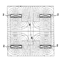
- 7A is an addition to the drawing (FIG. 8) published in Patent Document 4 and indicates the magnetic direction.
- FIG. 7B is a result of FEM analysis performed by the present inventor based on the magnetic field molding apparatus shown in FIG. 7A, and shows the strength of the magnetic field due to the density of the magnetic field lines. Also from FIG.
- Patent Document 1 proposes a semi-radial alignment treatment that can be taken in plural, but in terms of a magnetic field passing between adjacent magnet molded bodies (cavities), two alignment portions are considered. Is closed in the ring 51 which is a back yoke. For this reason, each orientation part is magnetically independent. Moreover, although the orientation part is magnetically independent, the mold 30 is interposed in vain between them, and the apparatus is easily increased in size. Incidentally, when the apparatus of Patent Document 1 is used, if the molded body is taken out after the alignment treatment, the magnetic field cannot be cut off because the alignment magnetic field is formed by a magnet. For this reason, the magnet powder of the compact is pulled by the orientation magnetic field, and the compact is easily damaged. Further, if the molded body is completely cured so that the molded body is not damaged, the molding takes about 30 minutes per time, and the productivity is greatly reduced.
- the present invention was made in view of such circumstances, and a rare earth anisotropy capable of efficiently producing a high performance cylindrical rare earth anisotropic bonded magnet having four or more poles in the radial direction. It aims at providing the manufacturing method of a bonded magnet, and the orientation processing method of the magnet molding suitable for it. Moreover, it aims at providing the shaping
- the present inventor has conducted intensive research to solve this problem, and as a result of repeated trial and error, when taking a plurality of magnet compacts, the main magnetic direction of the intermediate orientation magnetic field applied between adjacent cavities is aligned. came up with.
- a plurality of cylindrical rare earth anisotropic bonded magnets having four or more magnetic poles in the radial direction were succeeded.
- the bonded magnet obtained by this method has no deterioration in the magnetic characteristics in the circumferential direction as compared with a conventional bonded magnet that has been removed. And by developing this result, the present inventor has completed various inventions described below.
- the method for producing a rare earth anisotropic bonded magnet of the present invention includes at least two rare earth anisotropic magnet powders and a binder in at least two cylindrical cavities arranged adjacent to each other with the central axis in parallel.
- a uniform orientation magnetic field is applied to each cavity even when a plurality of the rare earth anisotropic bond magnets are taken at least in the stage of the heating orientation step.
- the orientation magnetic field penetrating between adjacent cavities is an intermediate orientation magnetic field in which the main magnetic directions are the same, a substantially uniform orientation magnetic field is also applied to the orientation portions of the magnet molded body facing each other between the adjacent cavities. .
- by performing such a heating alignment process it became possible to miniaturize the shaping
- the present invention is characterized by the orientation treatment method for the magnet raw material, and therefore can be grasped not only as a method for producing a rare earth anisotropic bonded magnet but also as an orientation treatment method for a magnet compact suitable for it.
- the present invention includes a filling step of filling at least two cylindrical cavities arranged parallel to each other with a central axis parallel to one or more rare earth anisotropic magnet powders and a resin as a binder, Heating the magnet raw material after the filling step to a temperature equal to or higher than the softening point of the resin so that the resin is softened or melted and an orientation magnetic field is applied to orient the rare earth anisotropic magnet powder into a semi-radial distribution.
- a molding step of obtaining a magnet molded body, and an orientation treatment method of the magnet molded body comprising:
- the heating and orientation step may be a method for orienting a magnet compact, wherein the main magnetic direction of the intermediate orientation magnetic field applied between the adjacent cavities is the same.
- this invention is grasped
- Softening the resin of a magnet raw material comprising a main yoke made of a magnetic material arranged in a substantially annular shape on the outer peripheral side of the cavity, and one or more rare earth anisotropic magnet powders filled in the cavity and a resin as a binder
- a heater capable of heating the resin to a temperature above the point to soften or melt the resin
- a magnetic field source capable of applying an orientation magnetic field from the main yoke to the magnet raw material filled in the cavity, and the cavity filled It is possible to obtain a cylindrical magnet molded body including a punch for pressurizing a magnet raw material and having at least four or more oriented portions oriented in a semi-radial distribution on the cylindrical side surface.
- an intermediate yoke made of a magnetic material that magnetically couples the main yokes disposed between the adjacent cavities is provided, and an intermediate medium having the same main magnetic direction between the adjacent cavities via the intermediate yokes.
- the magnetic field source preferably includes an intermediate electromagnetic coil wound around the intermediate yoke, and a current source that supplies a current in a predetermined direction to the intermediate electromagnetic coil.
- a magnetomotive force of a permanent magnet may be used as a magnetic field source for generating an orientation magnetic field, or an electromagnetic force obtained by supplying a current to an electromagnetic coil may be used. In any case, it is effective to form a magnetic circuit with a small magnetic resistance in order to efficiently apply the intermediate orientation magnetic field. Therefore, it is preferable to provide an intermediate yoke made of a magnetic material between adjacent cavities. When an electromagnetic coil is wound around the intermediate yoke, the intermediate yoke also serves as a magnetic core.
- a magnetic field source according to the magnetic field forming apparatus of the present invention includes an intermediate yoke made of a magnetic material disposed between the adjacent cavities, an electromagnetic coil wound around the intermediate yoke, and the electromagnetic It is preferable that the current source supply a current in a certain direction to the coil.
- the number of orientation portions formed on the peripheral side surface of the magnet molded body or the number of magnetic poles formed on the rare earth anisotropic bonded magnet after magnetizing the orientation portion is not particularly limited.
- the number is 4 or more in consideration of high performance and efficiency of the equipment in which the bond magnet is used.
- the number is usually an even number, and thus the number is preferably 4, 6, 8, 10, or the like.
- the method for producing a rare earth anisotropic bonded magnet of the present invention includes the above-described filling step, heating orientation step, and molding step, and a densification step in which the magnet compact is further compressed (heat compression) to be densified.
- a curing heat treatment step (curing heat treatment step), a magnetization step, a corrosion prevention step, and the like for firmly curing the thermosetting resin used for the magnet raw material may be provided.
- each step may be performed independently, or four or more steps may be performed at the same time.
- the weighing step for obtaining a powder compact obtained by preliminarily pressing the weighed magnet raw material powder and the above-described heating orientation step may be performed separately or at the same time. If performed separately, so-called batch processing becomes possible and mass productivity is improved. If done at the same time, the equipment burden can be reduced. The same applies to the densification step performed after the heating alignment step and the molding step.
- x to y in this specification includes the lower limit x and the upper limit y. Further, it should be noted that the lower limit and the upper limit described in the present specification can be arbitrarily combined to constitute a range such as “ab”.
- FIG. 1A It is a figure explaining the basic structure of the shaping
- FIG. 7B is a diagram obtained by FEM analysis of the magnetic direction around the cavity of the multiple-field forming apparatus in FIG. 7A.
- the present invention will be described in more detail with reference to embodiments of the invention.
- the content described in this specification including the following embodiments is not limited to the method for manufacturing a rare earth anisotropic bonded magnet according to the present invention, but also to an orientation processing method for a magnet compact and a molding apparatus in a magnetic field.
- the present invention is one or two arbitrarily selected from the configurations described in this specification. More than one can be added. The selected configuration can be added to any invention in a superimposed manner or arbitrarily beyond a category.
- rare earth anisotropic bonded magnet manufacturing method and magnet molded body orientation processing method The rare earth anisotropic bonded magnet manufacturing method or magnet molded body orientation processing method of the present invention includes the steps described above. However, since the heating orientation process is important in any case, the heating orientation process is additionally described.
- the heating orientation step is a step of orienting the rare earth anisotropic magnet powder into a semi-radial distribution by heating the resin of the magnet raw material filled in the cavity until it is softened or melted and applying an orientation magnetic field. .
- the orientation magnetic field is applied from the circumferential side surface of the cavity, whereby the rare earth anisotropic magnet powder is oriented in a semi-radial distribution at a specific orientation portion (semi-radial orientation).
- a cylindrical magnet molded body having at least four or more oriented portions on the cylindrical side surface is obtained. The heating temperature, heating time, molding pressure, strength of the applied orientation magnetic field, etc.
- the heating temperature is, for example, about 120 to 180 ° C.
- the molding pressure is, for example, about 50 to 500 MPa, and the time required for the heating and orientation step is about 0.5 to 10 seconds.
- the intensity of the applied orientation magnetic field varies depending on the viscosity of the thermosetting resin, but is about 0.4 to 1.8 T, for example.
- the “softened state” or “molten state” in the present invention is not strictly distinguished. In short, it is sufficient if the resin is heated to lower its viscosity and each particle of the rare earth anisotropic magnet powder can be rotated and moved.
- a magnetic raw material consists of one or more rare earth anisotropic magnet powders and a resin as a binder.
- a mixed powder of a rare earth anisotropic magnet powder and a resin powder a compound obtained by heating and kneading the mixed powder, a powder compact or a rare earth anisotropic magnet powder obtained by pressure-molding the mixed powder or compound,
- the magnet raw material may include additives such as a lubricant, a curing agent, a curing aid, and a surfactant in addition to the rare earth anisotropic magnet powder and the resin.
- the composition, type and the like of the rare earth anisotropic magnet powder are not limited, and any known magnet powder can be adopted.
- typical rare earth anisotropic magnet powders include Nd—Fe—B based magnet powder, Sm—Fe—N based magnet powder, SmCo based magnet powder and the like. These magnet powders may be manufactured by a so-called rapid solidification method or may be manufactured by a hydrotreating method (d-HDDR method, HDDR method).
- the rare earth anisotropic magnet powder may be one kind or plural kinds.
- a coarse powder having a relatively large average particle diameter for example, 1 to 250 ⁇ m
- a fine powder having a relatively small average particle diameter for example, 1 to 10 ⁇ m
- the resin a known material is used.
- polyamide synthetic resin such as nylon 12 and nylon 6, polyvinyl chloride, vinyl acetate copolymer thereof, MMA, PS, PPS, PE, PP, etc. are used alone or copolymerized.
- vinyl synthetic resins urethane, silicone, polycarbonate, PBT, PET, PEEK, CPE, thermoplastic resins such as hyperon, neoprene, SBR, and NBR, and thermosetting resins such as epoxy resin, phenol resin, and melamine resin.
- the resin may adhere to the particle surface of the rare earth anisotropic magnet powder in a powder form, or the particle surface may be coated in a film form.
- ⁇ Small amounts of various additives may be added to improve the mold release properties, the adjustment of molding timing, the wettability and adhesion between the magnet powder and the molten resin, and the like.
- additives include lubricants such as zinc stearate, aluminum stearate, alcohol lubricants, titanate or silane coupling agents, curing agents such as 4.4'-diaminodiphenylmethane (DDM), There are curing accelerators such as TPP-S (trade name of Hokuko Chemical Co., Ltd.).
- the mixing ratio of the rare earth anisotropic magnet powder and the resin is about 80 to 90% by volume of the magnet powder and about 10 to 20% by volume of the resin by volume ratio.
- the magnet powder is about 95 to 99% by mass
- the resin is about 1 to 5% by mass.
- the additive may be added in an amount of about 0.1 to 0.5% by volume.
- the rare earth anisotropic bonded magnet according to the present invention has a plurality of magnetic poles that emit magnetic flux from a cylindrical inner and outer peripheral side surface to a semi-radial distribution. The application, shape, size, magnetic properties, etc. are not questioned. Its typical use is in the field of motors.
- the motor may be a direct current (DC) motor or an alternating current (AC) motor. It may be an induction motor controlled by an inverter.
- the rare earth anisotropic bonded magnet may be disposed on the rotor (rotor) side or the stator (stator) side, or on the inner peripheral side or the outer peripheral side with respect to the central axis.
- Magnet raw material A magnetic raw material comprising a rare earth anisotropic magnet powder and a resin was prepared.
- This magnet raw material is an Nd—Fe—B system obtained by d-HDDR treatment (see Japanese Patent No. 3250551, Japanese Patent No. 3871219, etc.) (for example, atomic%, Nd: 12.5%, B : 6.4%, Ga: 0.3%, Nb: 0.2%, balance Fe) rare earth anisotropic magnet powder (hereinafter, simply referred to as “magnet powder”) and thermosetting resin.
- a compound obtained by heat-kneading an epoxy resin hereinafter, simply referred to as “resin” as appropriate) is pressure-molded.
- the compounding ratio of the resin in the compound was, for example, 1 to 5% by mass when the total compound was 100% by mass.
- the rare earth anisotropic magnet powder used here may be a mixture of Nd—Fe—B magnet powder and Sm—Fe—N magnet powder having a small particle diameter. (See Japanese Patent No. 3731597, etc.).
- this compound was not used as it was, but a raw material obtained by lightly pressing the compound weighed in a desired amount into a desired shape in advance was used as a magnet raw material.
- a weighing process and the below-mentioned heating orientation process etc. are separable.
- the weighing of the compound and the forming of the body are performed in a cold state, so that the weighing can be accurately obtained. Homogenization is also achieved.
- the magnet molded body obtained after the above-described molding process is not subjected to further heat compression molding, and is a two-stage molding including molding from a compound to a body and subsequent thermal orientation molding. did.
- a densification step of heating and compressing at a higher temperature and a higher pressure may be additionally performed after the molding step. In this case, three-stage molding is performed.
- the soft magnetic core is arranged on the inner peripheral side of the ring-shaped bonded magnet and the soft magnetic yoke is arranged on the outer peripheral side, and the radiation is mainly perpendicular to the central axis of the ring-shaped bonded magnet.
- the magnetic field direction at this time is not necessarily the same as the orientation magnetic field, and may be a uniform radiation direction (radial direction).
- the magnetic field in this case may be a semi-radially distributed magnetic field similar to the orientation magnetic field.
- it is possible to simultaneously magnetize a plurality of magnets by using a magnetizing device similar to a forming device in a magnetic field described later.
- a pulse magnetic field of about 2 to 5 T was used.
- a magnetic field molding apparatus capable of performing the above-described heating alignment process and molding process will be described.
- so-called two-piece forming in which two magnet molded bodies are simultaneously formed using the in-field forming apparatus S2 shown in FIG.
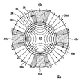
- FIGS. 1A to 1D the basic structure of a magnetic field forming device So (hereinafter, simply referred to as “device So”), which is a premise of the magnetic field forming device S2, will be described with reference to FIGS. 1A to 1D.
- device So a magnetic field forming device
- FIGS. 1A to 1D the basic structure of a magnetic field forming device S2
- the apparatus So includes a mold 30, a back yoke 42, an electromagnetic coil 46 (magnetic field source), a high-frequency induction heater (not shown) that heats and softens the resin in the magnet material, and the magnet material in the cavity. It consists of a punch (not shown) for pressure forming.
- the mold 30 includes a columnar core 32 made of a soft magnetic material disposed in the center, and a cylindrical first ring 34 made of a ferromagnetic superhard material inserted into the outer periphery of the core 32.
- the first ring 34 includes a first ring 34 and a cylindrical second ring 36 made of a ferromagnetic superhard material disposed with a certain gap on the outer peripheral side.
- An annular cavity 35 is formed between the first ring 34 and the second ring 36.
- first dice 38a, 38b, 38c, 38d (main yoke) made of a substantially sector-shaped ferromagnetic material divided into four parts, and a substantially sector shape provided between the first dice.
- Second dies 40a, 40b, 40c, and 40d (nonmagnetic portions) made of a nonmagnetic material such as stainless steel are disposed.
- the arc lengths in which the second dies 40a, 40b, 40c, and 40d contact the second ring 36 are sufficiently shorter than the arc lengths in which the first dies 38a, 38b, 38c, and 38d contact the second ring 36, respectively. It is set.
- the above-described mold 30 is configured by adding such a first die 38 and a second die 40 in addition to the core 32, the first ring 34 and the second ring 36.
- An annular back yoke 42 that is magnetically connected to each of the first dies 38a, 38b, 38c, and 38d to form a magnetic circuit is disposed around the outer periphery of the mold 30.
- the first dies 38a, 38b, 38c, 38d and the back yoke 42 are magnetically connected by substantially fan-shaped yoke pieces 43a, 43b, 43c, 43d, respectively.
- the electromagnetic coils 46a, 46b, 46c and 46d are wound around spaces 44a, 44b, 44c and 44d defined by the yoke pieces 43a, 43b, 43c and 43d, respectively.
- the electromagnetic coil 46a is wound between two adjacent spaces 44a and 44b so as to enclose a yoke piece 43a therebetween.
- FIG. 1D An example of the direction of the current supplied to the wound electromagnetic coil 46 is shown in FIG. 1D.
- X indicates that current flows from the front side to the back side of the paper surface
- ⁇ indicates that current flows from the back side to the front side of the paper surface.
- the direction of the generated magnetic field can be changed by changing the direction of the current flowing through the conducting wires of the electromagnetic coils 46a, 46b, 46c, and 46d.
- the direction of the current is adjusted by changing the winding direction of each electromagnetic coil, or by changing the direction of connection to the electrode of the power source.
- the orientation magnetic field is applied in that direction, thereby magnetizing the anisotropic magnet powder.
- Semi-radial orientation means that anisotropic magnet powder (group) in a rare earth anisotropic bonded magnet is oriented so as to have a semi-radial distribution by an orientation magnetic field.
- Semi-radial distribution means that the anisotropic magnet powder (group) in the rare earth anisotropic bonded magnet has an easy axis of magnetization of the anisotropic magnet powder in the normal direction of the cylindrical side surface at the main pole part of the magnetic pole.
- the south pole appears on the cylindrical inner surface of the orientation portion formed corresponding to the yoke piece 43a, and the orientation portion formed corresponding to the yoke piece 43b.
- An N pole appears on the inner surface of the cylinder.
- an S pole appears on the cylindrical inner surface of the orientation portion formed corresponding to the yoke piece 43c, and an N pole appears on the cylindrical inner surface of the orientation portion formed corresponding to the yoke piece 43d.
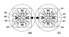
- FIG. 2A shows a case where S12 are simply arranged in parallel. In this case, as apparent from FIG. 2A, the distance between the adjacent cavities 351 and 352 is extended, and a useless space is formed between the back yokes 421 and 422, so that the apparatus cannot be reduced in size.
- an intermediate yoke 11 made of a ferromagnetic material is provided between the first rings 21 and 22 constituting the adjacent cavities C1 and C2, and the cavity C1 side of the intermediate yoke 11 is provided.
- a substantially square annular back yoke 12 is provided that allows current to flow through the electromagnetic coil 13 in the same direction and surrounds the cavities C1 and C2.
- the magnetomotive force generated in the electromagnetic coil 13 is applied to the cavities C1 and C2 through the intermediate yoke 11 also serving as the magnetic core, with the main magnetic direction becoming the same orientation magnetic field (intermediate orientation magnetic field). Since the orientation by the intermediate orientation magnetic field acts on the orientation portions of the cavities C1 and C2, the magnetomotive force of the electromagnetic coil 13 is the magnetomotive force of the electromagnetic coil in a portion other than the intermediate orientation magnetic field (for example, the outer periphery). It is approximately doubled.
- the current supplied from a current source (not shown) is equal to all the electromagnetic coils of the magnetic field forming apparatus S2 (for example, when the respective electromagnetic coils are connected in series), the number of turns in the electromagnetic coil 13 is set.
- the direction of the current flowing through the electromagnetic coil 13 may be as shown in FIG.
- the reference magnetic flux change is shown as a magnetic flux curve a, and the maximum and minimum values of the magnetic flux curve a are shown as ⁇ 1.
- the magnetic flux curve a has a uniform magnetic flux density distribution at each pole.
- the magnetic flux change of the ring-shaped bonded magnet obtained using the in-magnetic field molding device S13 is shown as a magnetic flux curve b.
- the orientation magnetic field reaches the saturation magnetic flux at that portion, and the magnetic loop that exits from the pole 3 and enters the pole 4 and the magnetic loop that exits from the pole 3 and enters the pole 2 ( (Magnetic flux passing through) becomes weak.
- the magnetic field strength in the cavity portion corresponding to the pole 3 is extremely weak, and the magnetic field strength in the cavity portion corresponding to the pole 4 and the pole 2 is also weakened.
- the peak value of the magnetic flux density of the magnetic flux curve b is pole 3 with respect to the peak value of the magnetic flux density of the magnetic flux density a. It decreases to about 50% at about 2, and it decreases to about 75% at the pole 2 and the pole 4. Therefore, when the ring-shaped bonded magnet obtained by using the magnetic field forming device S13 is used for a motor, the torque of the motor is greatly reduced and the cogging torque based on the non-uniformity of the magnetic flux density is also increased. .
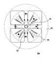
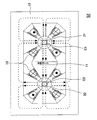
- FIG. 5 shows a magnetic field molding apparatus S3 that can obtain four more magnet compacts in one heating and orientation step.
- a broken line shown in FIG. 5 is a magnetic loop, and adjacent magnetic loops extending in parallel indicate that the magnetic directions are the same.
- another magnetic field molding apparatus S4 capable of obtaining four magnet compacts in one heating orientation step is shown in FIG.
- the cavities are evenly arranged vertically and horizontally, and four pieces (2 ⁇ 2) can be taken.
- the cavities are arranged in four rows on the left and right with one stage in the vertical direction. (1x4) can be taken.
- the broken lines shown in FIG. 6 are also magnetic loops, and adjacent magnetic loops extending in parallel indicate that the magnetic directions are the same.
- the in-magnetic field forming apparatus that can take a plurality of pieces is not limited to the case where the arrangement of the cavities is linear or rectangular. As long as the magnetic direction of the magnetic field generated in the intermediate yoke disposed between adjacent cavities is the same orientation magnetic field (intermediate orientation magnetic field), the arrangement of the cavities may be triangular, hexagonal, or the like.
Landscapes
- Engineering & Computer Science (AREA)
- Power Engineering (AREA)
- Manufacturing & Machinery (AREA)
- Chemical & Material Sciences (AREA)
- Crystallography & Structural Chemistry (AREA)
- Inorganic Chemistry (AREA)
- Manufacturing Cores, Coils, And Magnets (AREA)
- Permanent Field Magnets Of Synchronous Machinery (AREA)
- Hard Magnetic Materials (AREA)
- Powder Metallurgy (AREA)
Abstract
Description
一方、自動車小型ブラシモータに代表される小型動力用ブラシモータの分野では従来、2極分のフェライト焼結磁石を界磁に用いたフェライト2極モータが主流であった。しかし、最近では自動車の居住性の向上や車の燃費向上等を図るため、モータも同一出力での小型化やさらなる高出力化が要求されている。そこで、円筒状の希土類異方性ボンド磁石を用いたラジアル方向に4極以上の磁極を有するモータが登場してきた。この高性能モータを用いれば、従来のフェライト2極モータに対して、同一性能で体積を2分の1程度に大幅に小型化することが可能となる。そこで上記の分野においては、従来のフェライト2極モータが希土類異方性ボンド磁石を用いた多極モータへ置き換わりつつある(下記特許文献5等を参照)。
更に、その高性能モータのコギングトルクを改善するために、ラジアル方向に4極以上の磁極を有する円筒状の希土類異方性ボンド磁石の配向処理を工夫することが下記の特許文献1または特許文献2で提案されている。すなわち、これらの文献には、その配向処理を従来のラジアル配向から、いわゆるセミラジアル配向とすることで、モータの出力トルクが増大したり、コギングトルクが低減されることを開示している。
また、セミラジアル分布とは、希土類異方性ボンド磁石中の異方性磁石粉末(群)が、磁極の主極部では円筒側面の法線方向に異方性磁石粉末の磁化容易軸をもっており、磁極と磁極の間の遷移区間では異方性磁石粉末の磁化容易軸が磁極の中立点に近づくに連れて徐々に磁石の円筒側面の周回接線方向を向き、中立点では円筒側面の周回接線方向となり、中立点が遠ざかるに連れて徐々に円筒側面の法線方向となる円筒状の希土類異方性ボンド磁石中の異方性磁石粉末(群)の磁化容易軸の分布をいう。セミラジアル配向とは、希土類異方性ボンド磁石中の異方性磁石粉末(群)を、配向磁場によってセミラジアル分布をもつように配向させることをいい、磁化容易軸がすべてラジアル(放射状)方向に向いていない点(つまり、向きが一律でなく場所によって変化する点)で、一般的にいわれるラジアル配向と区別される。
またこの配向処理方法で製作した円筒状のリング磁石は、円筒方向に配向磁場の強弱に起因した表面磁束密度の不十分な部分が現れる。このため、このリング磁石を搭載したモータでは、モータ出力の低下、コギングトルクの増大を招いてしまう。このような事情もあり、ラジアル方向に4極以上の磁極を有する円筒状の希土類異方性ボンド磁石を、複数個を同時に一つの磁場成形装置で製造することはされていなかった。
(1)すなわち、本発明の希土類異方性ボンド磁石の製造方法は、中心軸を平行にして隣接配置された少なくとも二つの円筒状のキャビティへ一種以上の希土類異方性磁石粉末とバインダである樹脂とからなる磁石原料を充填する充填工程と、該充填工程後の磁石原料を前記樹脂の軟化点以上の温度に加熱して該樹脂を軟化状態または溶融状態としつつ配向磁場を印加して前記希土類異方性磁石粉末をセミラジアル分布へ配向させる加熱配向工程と、該加熱配向工程後にまたは該加熱配向工程と併行して配向された前記磁石原料を加圧成形してセミラジアル分布へ配向された少なくとも4以上の配向部を円筒側面に有する円筒状の磁石成形体を得る成形工程と、該磁石成形体を着磁して磁化された前記配向部を磁極とする着磁工程と、を備える希土類異方性ボンド磁石の製造方法であって、
前記加熱配向工程は、前記隣接するキャビティ間で印加される中間配向磁場の主たる磁気方向が同一であることを特徴とする。
そしてこのような加熱配向工程を行うことで、配向処理に用いる磁場中成形装置を、単に並列させた場合よりも遙かに小型化することが可能となった。
このように本発明は、磁石原料に対する配向処理方法に特徴があるため、希土類異方性ボンド磁石の製造方法としてのみならず、それに好適な磁石成形体の配向処理方法としても把握できる。
すなわち本発明は、中心軸を平行にして隣接配置された少なくとも二つの円筒状のキャビティへ一種以上の希土類異方性磁石粉末とバインダである樹脂とからなる磁石原料を充填する充填工程と、該充填工程後の磁石原料を前記樹脂の軟化点以上の温度に加熱して該樹脂を軟化状態または溶融状態としつつ配向磁場を印加して前記希土類異方性磁石粉末をセミラジアル分布へ配向させる加熱配向工程と、該加熱配向工程後にまたは該加熱配向工程と併行して配向された前記磁石原料を加圧成形してセミラジアル分布へ配向された少なくとも4以上の配向部を円筒側面に有する円筒状の磁石成形体を得る成形工程と、を備える磁石成形体の配向処理方法であって、
前記加熱配向工程は、前記隣接するキャビティ間で印加される中間配向磁場の主たる磁気方向が同一であることを特徴とする磁石成形体の配向処理方法としてもよい。
(1)さらに本発明では、前述したように、隣接するキャビティ間を貫く配向磁場を主たる磁気方向が同一となる中間配向磁場としたため、キャビティの配向部を貫く無駄のない磁気ループの形成が可能となった。このため、隣接するキャビティ間に配設される磁気回路を構成するヨーク(金型として用いられるダイス等を含む)の短縮を図ることが可能となり、加熱配向工程で用いる磁場中成形装置の小型化をも図れるようになった。
さらに、前記隣接するキャビティ間に配設された前記主ヨークを磁気的に連結する磁性材からなる中間ヨークを備え、該中間ヨークを介して前記隣接するキャビティ間に主たる磁気方向を同一とする中間配向磁場を印加できることを特徴とする磁場中成形装置としてもよい。
特に、前記磁場源は、該中間ヨークの周囲に巻回された中間電磁コイルと、該中間電磁コイルへ一定方向の電流を供給する電流源とを有すると好適である。
そこで例えば、本発明の磁場中成形装置に係る磁場源は、前記隣接するキャビティ間に配設された磁性材からなる中間ヨークと、該中間ヨークの周囲に巻回された電磁コイルと、該電磁コイルへ一定方向の電流を供給する電流源とからなると、好適である。
(1)本発明では、磁石成形体の周側面に形成される配向部の数またはその配向部を着磁した後の希土類異方性ボンド磁石に形成される磁極の数は特に問わないが、ボンド磁石の使用される機器の高性能化、効率化等を考慮して、その数は4以上である。モータ用ボンド磁石(特にDCモータ用ボンド磁石)であれば、その数は通常偶数であるから、その数は4、6、8、10などであると好ましい。
C1、C2 キャビティ
11 中間ヨーク
12 バックヨーク
13 電磁コイル
(1)希土類異方性ボンド磁石の製造方法および磁石成形体の配向処理方法
本発明の希土類異方性ボンド磁石の製造方法または磁石成形体の配向処理方法は、前述したような各工程からなるが、いずれの場合も加熱配向工程が重要となることから、加熱配向工程について付言しておく。
なお、本発明でいう「軟化状態」または「溶融状態」は厳密に区別されるものではない。要するに、樹脂が加熱されてその粘性が低下し、希土類異方性磁石粉末の各粒子が回転、移動等が可能な状態となれば十分である。
磁石原料は、一種以上の希土類異方性磁石粉末とバインダである樹脂とからなる。具体的には例えば、希土類異方性磁石粉末と樹脂粉末との混合粉末、その混合粉末を加熱混練したコンパウンド、その混合粉末やコンパウンドを加圧成形した粉末成形体や希土類異方性磁石粉末と溶融した樹脂との混合体などである。ちなみに、磁石原料は、希土類異方性磁石粉末および樹脂のみならず、その他に潤滑剤、硬化剤、硬化助剤、界面活性剤等の添加剤を含んでもよい。
本発明に係る希土類異方性ボンド磁石は、円筒状の内外周側面からセミラジアル分布へ磁束を放出する複数の磁極を有する。その用途、形状、サイズ、磁気特性等を問わない。
その代表的な用途はモータの界磁である。そのモータは直流(DC)モータでも交流(AC)モータでもよい。インバータ制御されるインダクションモータ等であってもよい。また、希土類異方性ボンド磁石の配設位置は、回転子(ロータ)側でも固定子(ステータ)側でも、さらには中心軸に対して内周側でも外周側でもよい。
〈希土類異方性ボンド磁石の製造方法〉
本実施例では、本発明の希土類異方性ボンド磁石の製造方法の一例として、4極DCブラシモータの筐体内に収容される永久磁石であって、その界磁を構成する中空円筒形状のリング状ボンド磁石(希土類異方性ボンド磁石)を製造する場合を取り上げて説明する。具体的には、本実施例のリング状ボンド磁石は次のようにして製造される。
希土類異方性磁石粉末と樹脂とからなる磁石原料を用意した。この磁石原料は、d-HDDR処理(日本特許第3250551号、日本特許第3871219号など参照)して得られたNd-Fe-B系(例えば、原子%で、Nd:12.5%、B:6.4%、Ga:0.3%、Nb:0.2%、残部Fe)の希土類異方性磁石粉末(以下適宜、単に「磁石粉末」という。)と、熱硬化性樹脂であるエポキシ樹脂(以下適宜、単に「樹脂」という。)とを加熱混練したコンパウンドを加圧成形したものである。
コンパウンド中の樹脂の配合割合は、例えば、コンパウンド全体を100質量%としたときに1~5質量%でとした。また、ここで用いる希土類異方性磁石粉末は、Nd-Fe-B系磁石粉末の他、粒径の小さいSm-Fe-N系磁石粉末等を混在させたものでもよい。(日本特許第3731597号など参照)。
磁場中成形装置(詳細は後述)のキャビティへ前述の磁石原料(素形体)を充填する(充填工程)。次に、その磁石原料を加熱し、樹脂を軟化させて配向磁場を印加し(加熱配向工程)、圧縮成形(成形工程)を行う。これによりリング状ボンド磁石のベースとなる磁石成形体が得られる。ちなみに、加熱配向工程や成形工程の設定条件は、例えば、加熱温度:120~180℃、成形圧力:50~500MPa、配向磁場:0.4~1.5T、工程時間:0.5~10秒である。
磁石成形体をさらに加熱して、磁石原料中のエポキシ樹脂を加熱硬化させるキュア熱処理を行った(加熱硬化工程)。これにより、高強度で耐熱性に優れるリング状ボンド磁石が得られる。この加熱硬化処理した磁石成形体に対して着磁することで、後述するように、4極DCブラシモータ用の4極にセミラジアル配向したリング状ボンド磁石が得られる。ちなみにキュア熱処理は、140~180℃の炉中に磁石成形体を15~60分間程度保持してなされる。
なお、着磁工程は、リング状ボンド磁石の内周側に軟磁性コアを配置し、外周側に軟磁性ヨークを配置した状態で、リング状ボンド磁石の中心軸に対して主に垂直な放射方向(ラジアル方向)に磁場を印加させてなされる。このときの磁場方向は、必ずしも配向磁場と同じである必要はなく、均一な放射方向(ラジアル方向)であっても良い。勿論、この場合の磁場は、配向磁場と同様なセミラジアル分布した磁場であってもよい。この際、後述する磁場中成形装置と同様な着磁装置を用いることで、複数個同時に着磁することも可能である。着磁には2~5T程度のパルス磁場を用いた。
上述した加熱配向工程および成形工程を行うことができる磁場中成形装置について説明する。本実施例では、一例として図3に示す磁場中成形装置S2を用いて2個の磁石成形体を同時に成形する、いわゆる2個取りを行った。
先ず、磁場中成形装置S2の前提となる磁場中成形装置So(以下適宜、単に「装置So」という。)の基本構造を図1A~図1Dを用いて説明する。これらの図面上では、磁場中成形装置の基本構造を簡便に説明するために、敢えてキャビティ1個分について示してある。図1Aは装置Soの平面断面図であり、図1Bは装置Soの縦断面図であり、図1Cは装置Soのキャビティ周辺の詳細断面図である。
装置Soは、金型30と、バックヨーク42と、電磁コイル46と(磁場源)と、磁石原料中の樹脂を加熱軟化させる高周波誘導加熱器(図示せず)と、キャビティ内の磁石原料を加圧成形するパンチ(図示せず)とからなる。
この磁場が印加される状況下で前述した加熱配向工程を行うと、上下左右略対称な4つの配向部でセミラジアル配向した磁石成形体が得られる。なお、図1Cに示すように、磁力線が大きく変化する遷移区間によって、4つの配向部が形成される。
ここで配向とは、磁場配向のことであり、異方性磁石粉末の磁化容易軸を所定の方向へ配列させるために、その方向へ配向磁場を印加することによって、異方性磁石粉末の磁化容易軸をその磁場の方向へ沿うように回転させることをいう。セミラジアル配向とは、希土類異方性ボンド磁石中の異方性磁石粉末(群)を、配向磁場によってセミラジアル分布をもつように配向させることをいう。また、セミラジアル分布とは、希土類異方性ボンド磁石中の異方性磁石粉末(群)が、磁極の主極部では円筒側面の法線方向に異方性磁石粉末の磁化容易軸をもっており、磁極と磁極の間の遷移区間では異方性磁石粉末の磁化容易軸が磁極の中立点に近づくに連れて徐々に磁石の円筒側面の周回接線方向を向き、中立点では円筒側面の周回接線方向となり、中立点が遠ざかるに連れて徐々に円筒側面の法線方向となる円筒状の希土類異方性ボンド磁石中の異方性磁石粉末(群)の磁化容易軸の分布をいう。磁化容易軸がすべてラジアル(放射状)方向に向いていない点(つまり、向きが一律でなく場所によって変化する点)で、一般的にいわれるラジアル配向と異なる。
上述の基本構造を踏まえて、一度の加熱配向工程で2個のリング状の磁石成形体を得ることができる本実施例の磁場中成形装置S2の構造について、順を追って説明する。
先ず、前述した金型30、バックヨーク42、電磁コイル46等に相当する金型301、302、バックヨーク421、422、電磁コイル461、462等からなる1個取り用の磁場中成形装置S11、S12を単に並列させた場合を図2Aに示した。この場合、図2Aから明らかなように、隣接するキャビティ351、352間の距離が延び、バックヨーク421、422間に無駄なスペースが形成されてしまい、装置の小型化を図れない。
そこで本実施例では、図3に示すように、隣接するキャビティC1、C2を構成する第1リング21、22間に、強磁性材からなる中間ヨーク11を設け、その中間ヨーク11のキャビティC1側およびキャビティC2側の両方で、電磁コイル13を同じ向きに電流を流すと共に、キャビティC1、C2を共に包囲する略方形環状のバックヨーク12を設けた。
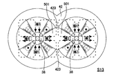
本実施例に係る磁場中成形装置S2を用いて得られたリング状ボンド磁石一個(極1~極4)の磁気特性と、図2Aに示す磁場中成形装置S11(磁場の干渉しない従来の磁場中成形装置を、単純に2台並べた場合)および図2Bに示す磁場中成形装置S13を用いて得られたリング状ボンド磁石一個(極1~極4)の磁気特性とを測定した結果を図4に併せて示した。なお、ここで測定した磁気特性は、リング状ボンド磁石の表面磁束密度のラジアル成分の角度分布である。また、図4に示した磁束密度は相対値であり、基準としたのは磁場中成形装置S11を用いて得られたリング状ボンド磁石の各極における磁束変化である。図4中には、この基準となる磁束変化を磁束カーブaとし、その磁束カーブaの極大値および極小値を±1として示した。図4からも明らかなように、磁束カーブaは磁束密度分布が各極で均一な特性となっている。
磁場中成形装置S13を用いて得られたリング状ボンド磁石の磁束変化を磁束カーブbとして示した。この場合、バックヨーク連結部423が狭いために、その部分で配向磁場が飽和磁束に到達して、極3から出て極4へ入る磁気ループおよび極3から出て極2へ入る磁気ループ(を通過する磁束)が弱くなってしまう。その結果、極3に対応するキャビティ部分における磁場強さが極端に弱くなり、また、極4および極2に対応するキャビティ部分における磁場強さも弱くなり、それらの部分で十分な配向をさせることができない。つまり、磁場中成形装置S13を用いて複数個取りしようとした場合、従来の磁場中成形装置S11などで1個取りしていた場合と同等な配向磁場を出力させることはできない。より具体的にいえば、磁束カーブbと磁束カーブaとを対比すれば明らかなように、磁束カーブbの磁束密度のピーク値は、磁束密度aの磁束密度のピーク値に対して、極3で約50%程度にまで低下し、また、極2および極4で約75%程度までに低下する。従って、磁場中成形装置S13を用いて得られたリング状ボンド磁石をモータに使用した場合、そのモータのトルクは大幅に低下するとともに磁束密度の不均一性に基づくコギングトルクも増大して好ましくない。
これらに対して本実施例の磁場中成形装置S2を用いて得られたリング状ボンド磁石の場合、その磁束変化を示した磁束カーブcからもわかるように、従来の磁場中成形装置S11などで1個取りしていた場合(磁束カーブa)と同等な配向磁場が出力されていたことが解る。これは磁場中成形装置S13を用いた場合と異なり、磁気通路に狭い部分がないため、配向磁場を印加した際に、磁気ループ上に磁束が弱められる部分がなかったためである。
図5に、一度の加熱配向工程でさらに4個の磁石成形体を得ることができる磁場中成形装置S3を示した。図5中に示した破線は磁気ループであり、隣接して平行に伸びる磁気ループは、磁気方向が同一であることを示す。また、図5に示した磁場中成形装置S3と同様に、一度の加熱配向工程で4個の磁石成形体を得ることができる別の磁場中成形装置S4を図6に示した。
さらに、複数個取りできる磁場中成形装置は、各キャビティの配置が直線的または方形的な場合に限られない。隣接するキャビティ間に配設した中間ヨークに発生させる磁場の磁気方向が同一の配向磁場(中間配向磁場)となっている限り、各キャビティの配置は三角形的、六角形的等でもよい。
Claims (4)
- 中心軸を平行にして隣接配置された少なくとも二つの円筒状のキャビティへ一種以上の希土類異方性磁石粉末とバインダである樹脂とからなる磁石原料を充填する充填工程と、
該充填工程後の磁石原料を前記樹脂の軟化点以上の温度に加熱して該樹脂を軟化状態または溶融状態としつつ配向磁場を印加して前記希土類異方性磁石粉末をセミラジアル分布へ配向させる加熱配向工程と、
該加熱配向工程後にまたは該加熱配向工程と併行して配向された前記磁石原料を加圧成形してセミラジアル分布へ配向された少なくとも4以上の配向部を円筒側面に有する円筒状の磁石成形体を得る成形工程と、
該磁石成形体を着磁して磁化された前記配向部を磁極とする着磁工程と、を備える希土類異方性ボンド磁石の製造方法であって、
前記加熱配向工程は、前記隣接するキャビティ間で印加される中間配向磁場の主たる磁気方向が同一であることを特徴とする希土類異方性ボンド磁石の製造方法。 - 中心軸を平行にして隣接配置された少なくとも二つの円筒状のキャビティへ一種以上の希土類異方性磁石粉末とバインダである樹脂とからなる磁石原料を充填する充填工程と、
該充填工程後の磁石原料を前記樹脂の軟化点以上の温度に加熱して該樹脂を軟化状態または溶融状態としつつ配向磁場を印加して前記希土類異方性磁石粉末をセミラジアル分布へ配向させる加熱配向工程と、
該加熱配向工程後にまたは該加熱配向工程と併行して配向された前記磁石原料を加圧成形してセミラジアル分布へ配向された少なくとも4以上の配向部を円筒側面に有する円筒状の磁石成形体を得る成形工程と、を備える磁石成形体の配向処理方法であって、
前記加熱配向工程は、前記隣接するキャビティ間で印加される中間配向磁場の主たる磁気方向が同一であることを特徴とする磁石成形体の配向処理方法。 - 中心軸を平行にして隣接配置された少なくとも二つの円筒状のキャビティおよび該キャビティの内周側に磁心となるコアと、
非磁性部を介在させて少なくとも4以上に分割され、該キャビティの外周側に略環状に配置された磁性材からなる主ヨークと、
該キャビティへ充填される一種以上の希土類異方性磁石粉末とバインダである樹脂とからなる磁石原料を該樹脂の軟化点以上の温度に加熱して該樹脂を軟化状態または溶融状態にできる加熱器と、
該キャビティへ充填された磁石原料へ前記主ヨークから配向磁場を印加できる磁場源と、
前記キャビティに充填された磁石原料を加圧するパンチとを備え、セミラジアル分布へ配向された少なくとも4以上の配向部を円筒側面に有する円筒状の磁石成形体を得ることができる磁場中成形装置であって、
さらに、前記隣接するキャビティ間に配設された前記主ヨークを磁気的に連結する磁性材からなる中間ヨークを備え、該中間ヨークを介して前記隣接するキャビティ間に主たる磁気方向を同一とする中間配向磁場を印加できることを特徴とする磁場中成形装置。 - 前記磁場源は、該中間ヨークの周囲に巻回された中間電磁コイルと、該中間電磁コイルへ一定方向の電流を供給する電流源とを有する請求項3に記載の磁場中成形装置。
Priority Applications (5)
| Application Number | Priority Date | Filing Date | Title |
|---|---|---|---|
| JP2010503313A JP4605317B2 (ja) | 2008-09-12 | 2008-09-12 | 希土類異方性ボンド磁石の製造方法、磁石成形体の配向処理方法および磁場中成形装置 |
| CN200880001597A CN101779364A (zh) | 2008-09-12 | 2008-09-12 | 稀土类各向异性粘结磁铁的制造方法、磁铁成形体的定向处理方法及磁场中成形装置 |
| KR1020097014146A KR20110057056A (ko) | 2008-09-12 | 2008-09-12 | 희토류 이방성 본드 자석의 제조 방법, 자석 성형체의 배향 처리 방법 및 자장안성형 장치 |
| PCT/JP2008/066591 WO2010029642A1 (ja) | 2008-09-12 | 2008-09-12 | 希土類異方性ボンド磁石の製造方法、磁石成形体の配向処理方法および磁場中成形装置 |
| US12/461,667 US20100065156A1 (en) | 2008-09-12 | 2009-08-20 | Method for producing rare earth anisotropic bond magnets, method for orientation processing of magnetic molded bodies, and in-magnetic filed molding apparatus |
Applications Claiming Priority (1)
| Application Number | Priority Date | Filing Date | Title |
|---|---|---|---|
| PCT/JP2008/066591 WO2010029642A1 (ja) | 2008-09-12 | 2008-09-12 | 希土類異方性ボンド磁石の製造方法、磁石成形体の配向処理方法および磁場中成形装置 |
Related Child Applications (1)
| Application Number | Title | Priority Date | Filing Date |
|---|---|---|---|
| US12/461,667 Continuation US20100065156A1 (en) | 2008-09-12 | 2009-08-20 | Method for producing rare earth anisotropic bond magnets, method for orientation processing of magnetic molded bodies, and in-magnetic filed molding apparatus |
Publications (1)
| Publication Number | Publication Date |
|---|---|
| WO2010029642A1 true WO2010029642A1 (ja) | 2010-03-18 |
Family
ID=42004910
Family Applications (1)
| Application Number | Title | Priority Date | Filing Date |
|---|---|---|---|
| PCT/JP2008/066591 Ceased WO2010029642A1 (ja) | 2008-09-12 | 2008-09-12 | 希土類異方性ボンド磁石の製造方法、磁石成形体の配向処理方法および磁場中成形装置 |
Country Status (5)
| Country | Link |
|---|---|
| US (1) | US20100065156A1 (ja) |
| JP (1) | JP4605317B2 (ja) |
| KR (1) | KR20110057056A (ja) |
| CN (1) | CN101779364A (ja) |
| WO (1) | WO2010029642A1 (ja) |
Cited By (2)
| Publication number | Priority date | Publication date | Assignee | Title |
|---|---|---|---|---|
| JP2017070031A (ja) * | 2015-09-29 | 2017-04-06 | ダイキン工業株式会社 | ロータ |
| JP2017073782A (ja) * | 2010-12-23 | 2017-04-13 | プレシエント オーディオ エムエフジー リミテッド ライアビリティー カンパニーPrescient Audio MFG LLC | 薄型スピーカー |
Families Citing this family (4)
| Publication number | Priority date | Publication date | Assignee | Title |
|---|---|---|---|---|
| KR101407837B1 (ko) * | 2010-04-05 | 2014-06-16 | 아이치 세이코우 가부시키가이샤 | 이방성 본드 자석의 제조 방법 및 그 제조 장치 |
| JP2018182084A (ja) * | 2017-04-14 | 2018-11-15 | 日立金属株式会社 | リング状ボンド磁石、ボイスコイルモータ、及びボイスコイルモータの製造方法 |
| JP7543963B2 (ja) * | 2021-03-26 | 2024-09-03 | 株式会社デンソー | ボンド磁石およびその製造方法 |
| US20240388151A1 (en) * | 2021-09-29 | 2024-11-21 | Aichi Steel Corporation | Rotor and electric motor |
Citations (4)
| Publication number | Priority date | Publication date | Assignee | Title |
|---|---|---|---|---|
| JPH09320876A (ja) * | 1996-03-29 | 1997-12-12 | Sumitomo Special Metals Co Ltd | 異方性ボンド磁石の製造方法 |
| JP2004023085A (ja) * | 2002-06-20 | 2004-01-22 | Aichi Steel Works Ltd | モータ用異方性ボンド磁石の配向処理方法 |
| JP2005286081A (ja) * | 2004-03-30 | 2005-10-13 | Shin Etsu Chem Co Ltd | 異方性磁石の製造に用いる金型、成形機、方法及び得られる磁石 |
| WO2005104337A1 (ja) * | 2004-04-20 | 2005-11-03 | Aichi Steel Corporation | 4磁極モータ用異方性ボンド磁石、それを用いたモータ及び4磁極モータ用異方性ボンド磁石の配向処理装置 |
Family Cites Families (4)
| Publication number | Priority date | Publication date | Assignee | Title |
|---|---|---|---|---|
| JPH0624174B2 (ja) * | 1985-07-12 | 1994-03-30 | 三菱化成株式会社 | 円筒磁石の製造方法 |
| JPH0624175B2 (ja) * | 1985-07-12 | 1994-03-30 | 三菱化成株式会社 | リング状磁性成形体の製造方法 |
| JP2816668B2 (ja) * | 1996-07-04 | 1998-10-27 | 愛知製鋼株式会社 | 磁気異方性樹脂結合型磁石の製造方法 |
| JP3480733B2 (ja) * | 2001-12-10 | 2003-12-22 | 愛知製鋼株式会社 | Dcブラシモータ装置及びその永久磁石 |
-
2008
- 2008-09-12 JP JP2010503313A patent/JP4605317B2/ja active Active
- 2008-09-12 KR KR1020097014146A patent/KR20110057056A/ko not_active Withdrawn
- 2008-09-12 CN CN200880001597A patent/CN101779364A/zh active Pending
- 2008-09-12 WO PCT/JP2008/066591 patent/WO2010029642A1/ja not_active Ceased
-
2009
- 2009-08-20 US US12/461,667 patent/US20100065156A1/en not_active Abandoned
Patent Citations (4)
| Publication number | Priority date | Publication date | Assignee | Title |
|---|---|---|---|---|
| JPH09320876A (ja) * | 1996-03-29 | 1997-12-12 | Sumitomo Special Metals Co Ltd | 異方性ボンド磁石の製造方法 |
| JP2004023085A (ja) * | 2002-06-20 | 2004-01-22 | Aichi Steel Works Ltd | モータ用異方性ボンド磁石の配向処理方法 |
| JP2005286081A (ja) * | 2004-03-30 | 2005-10-13 | Shin Etsu Chem Co Ltd | 異方性磁石の製造に用いる金型、成形機、方法及び得られる磁石 |
| WO2005104337A1 (ja) * | 2004-04-20 | 2005-11-03 | Aichi Steel Corporation | 4磁極モータ用異方性ボンド磁石、それを用いたモータ及び4磁極モータ用異方性ボンド磁石の配向処理装置 |
Cited By (2)
| Publication number | Priority date | Publication date | Assignee | Title |
|---|---|---|---|---|
| JP2017073782A (ja) * | 2010-12-23 | 2017-04-13 | プレシエント オーディオ エムエフジー リミテッド ライアビリティー カンパニーPrescient Audio MFG LLC | 薄型スピーカー |
| JP2017070031A (ja) * | 2015-09-29 | 2017-04-06 | ダイキン工業株式会社 | ロータ |
Also Published As
| Publication number | Publication date |
|---|---|
| JPWO2010029642A1 (ja) | 2012-02-02 |
| KR20110057056A (ko) | 2011-05-31 |
| JP4605317B2 (ja) | 2011-01-05 |
| CN101779364A (zh) | 2010-07-14 |
| US20100065156A1 (en) | 2010-03-18 |
Similar Documents
| Publication | Publication Date | Title |
|---|---|---|
| KR101407837B1 (ko) | 이방성 본드 자석의 제조 방법 및 그 제조 장치 | |
| KR100908424B1 (ko) | 자기 회로용 부품 및 그 제조 방법 | |
| US5886070A (en) | Production method for anisotropic resin-bonded magnets | |
| US7230514B2 (en) | Inductive component and method for producing same | |
| US6509667B1 (en) | Rotor for a reluctance motor | |
| CN101080862B (zh) | 电动机用转子及其制造方法 | |
| JP4605317B2 (ja) | 希土類異方性ボンド磁石の製造方法、磁石成形体の配向処理方法および磁場中成形装置 | |
| JP2005064448A (ja) | 積層極異方複合磁石の製造方法 | |
| JP3060104B2 (ja) | ラジアル配向した磁気異方性樹脂結合型磁石及びその製造方法 | |
| JPWO2004027795A1 (ja) | ボンド磁石の製造方法及びボンド磁石を備えた磁気デバイスの製造方法 | |
| Kim et al. | A new anisotropic bonded NdFeB permanent magnet and its application to a small DC motor | |
| CN111354559A (zh) | 用于形成对准的磁芯的固定装置和方法 | |
| JP2004023085A (ja) | モータ用異方性ボンド磁石の配向処理方法 | |
| JPH11176682A (ja) | ボンド(登録商標)磁石の製造方法 | |
| CN104160599B (zh) | 用于制造机器元件的方法和用于电机的机器元件 | |
| JP2006041138A (ja) | 磁極面球状ボンド磁石およびその製造方法 | |
| JP2020053515A (ja) | 多極ボンド磁石複合体の製造方法 | |
| JPH06260328A (ja) | 円筒状異方性磁石およびその製造方法 | |
| JP3182979B2 (ja) | 異方性磁石、その製造方法および製造装置 | |
| JPH08130143A (ja) | 異方性ボンド磁石の製造方法および異方性ボンド磁石 | |
| JPS612305A (ja) | C型異方性樹脂ボンド磁石の製造方法 | |
| JP2003153504A (ja) | 円筒状ボンド磁石及びその製造方法 | |
| JPH1167568A (ja) | ボンド磁石の製造方法 | |
| JP2004134698A (ja) | 磁石製造方法及びその装置 | |
| WO1991001562A1 (fr) | Aimant anisotropique lie par une substance plastique |
Legal Events
| Date | Code | Title | Description |
|---|---|---|---|
| WWE | Wipo information: entry into national phase |
Ref document number: 200880001597.4 Country of ref document: CN |
|
| WWE | Wipo information: entry into national phase |
Ref document number: 1020097014146 Country of ref document: KR |
|
| WWE | Wipo information: entry into national phase |
Ref document number: 2008810642 Country of ref document: EP |
|
| WWE | Wipo information: entry into national phase |
Ref document number: 2010503313 Country of ref document: JP |
|
| 121 | Ep: the epo has been informed by wipo that ep was designated in this application |
Ref document number: 08810642 Country of ref document: EP Kind code of ref document: A1 |
|
| NENP | Non-entry into the national phase |
Ref country code: DE |
|
| 122 | Ep: pct application non-entry in european phase |
Ref document number: 08810642 Country of ref document: EP Kind code of ref document: A1 |